EP3523618B1 - Abbildungssystem zur inspektion von mehradrigen lichtwellenleiterverbindern - Google Patents
Abbildungssystem zur inspektion von mehradrigen lichtwellenleiterverbindern Download PDFInfo
- Publication number
- EP3523618B1 EP3523618B1 EP16785266.4A EP16785266A EP3523618B1 EP 3523618 B1 EP3523618 B1 EP 3523618B1 EP 16785266 A EP16785266 A EP 16785266A EP 3523618 B1 EP3523618 B1 EP 3523618B1
- Authority
- EP
- European Patent Office
- Prior art keywords
- image
- wavelengths
- imaging system
- autofocus
- illumination
- Prior art date
- Legal status (The legal status is an assumption and is not a legal conclusion. Google has not performed a legal analysis and makes no representation as to the accuracy of the status listed.)
- Active
Links
Images







Classifications
-
- G—PHYSICS
- G01—MEASURING; TESTING
- G01M—TESTING STATIC OR DYNAMIC BALANCE OF MACHINES OR STRUCTURES; TESTING OF STRUCTURES OR APPARATUS, NOT OTHERWISE PROVIDED FOR
- G01M11/00—Testing of optical apparatus; Testing structures by optical methods not otherwise provided for
- G01M11/30—Testing of optical devices, constituted by fibre optics or optical waveguides
- G01M11/31—Testing of optical devices, constituted by fibre optics or optical waveguides with a light emitter and a light receiver being disposed at the same side of a fibre or waveguide end-face, e.g. reflectometers
-
- G—PHYSICS
- G01—MEASURING; TESTING
- G01M—TESTING STATIC OR DYNAMIC BALANCE OF MACHINES OR STRUCTURES; TESTING OF STRUCTURES OR APPARATUS, NOT OTHERWISE PROVIDED FOR
- G01M11/00—Testing of optical apparatus; Testing structures by optical methods not otherwise provided for
- G01M11/30—Testing of optical devices, constituted by fibre optics or optical waveguides
- G01M11/33—Testing of optical devices, constituted by fibre optics or optical waveguides with a light emitter being disposed at one fibre or waveguide end-face, and a light receiver at the other end-face
-
- G—PHYSICS
- G02—OPTICS
- G02B—OPTICAL ELEMENTS, SYSTEMS OR APPARATUS
- G02B6/00—Light guides; Structural details of arrangements comprising light guides and other optical elements, e.g. couplings
- G02B6/24—Coupling light guides
- G02B6/36—Mechanical coupling means
- G02B6/38—Mechanical coupling means having fibre to fibre mating means
- G02B6/3807—Dismountable connectors, i.e. comprising plugs
- G02B6/3833—Details of mounting fibres in ferrules; Assembly methods; Manufacture
- G02B6/385—Accessories for testing or observation of connectors
Definitions
- This disclosure generally relates to fiber optic connector inspection, and more particularly to microscopes used to inspect multifiber connectors.
- Fiber optic links are key elements in many local and wide area digital broadband networks. However, even micron-sized dust particles or defects in the endface of a fiber optic connector can cause a link to fail. Thus technicians who install or maintain fiber optic equipment or cables in the field, as well as associates who perform assembly or quality assurance functions at facilities that manufacture fiber optic equipment or cable assemblies, are normally required to inspect the endface of every fiber optic connector before it is mated with another connector.
- MPO multiple-fiber connector type
- Multifiber adapters for single-fiber connector inspection microscopes are disclosed in U.S. Pat. No. 8,104,976 (Zhou et. al.) , U.S. Pat. No. 7,239,788 (Villeneuve ), and U.S. Pat. No. 6,879,439 (Cassady ). However, these systems must be operated manually and therefore may be slow or difficult to use.
- the FOV of each image captured by the sensor, or the sensor FOV must also have a width of 4.6 mm, as shown in FIG. 2 .
- the required sensor size in terms of pixels would equal [2/3][9600] 2 or about 56 million pixels (Mp).
- Mp the resolution of current art, single-fiber microscopes, or about 0.5 microns, then a pixel density of 4 pixels per micron may be required. In this case the image sensor would require over 200 million pixels.
- This description discloses multiple exemplary embodiments of an imaging system that can automatically capture multiple images of the endface of a multiple-fiber connector, wherein the images together encompass the endfaces of all of the individual fibers terminated by the connector.
- One example embodiment includes a three-wavelength illumination source, a wavelength-controlled FOV shifter, and a single image sensor.
- the FOV-shifter component further comprises two dichroic beam-splitters and an additional mirror which can be dichroic or broadband, disposed in front of the endface under inspection, wherein the dichroic beamsplitters and the additional mirror are positioned in the optical path in sequence, and each of the dichroic mirrors reflects one of the wavelengths generated by the illumination source and passes the remaining wavelengths so that the current illumination wavelength determines which endface section is illuminated.
- the image sensor will see the left, middle, or right section of the endface under inspection at any given time, depending on which illumination wavelength is active.
- the FOV of the objective lens and the pixel count of the image sensor must be large enough to achieve an image FOV of only about 1/3 of the total endface area.
- the single image sensor of the aforementioned embodiment is replaced by an image beam-splitter used to create two image planes, and two image sensors, wherein each image sensor is disposed on a different image plane.
- This embodiment may be used to increase microscope FOV without using a much more expensive image sensor type.
- the first includes an optical path length equalizer component before the autofocus optical system, which may be implemented with dichroic beam-splitters and mirrors.
- the second includes an image separator and one image sensor per wavelength, wherein the image separator comprises one or more dichroic beam-splitters, and wherein the distance between each of these sensors and the wavelength separator is selected to achieve the same optical path length at each illumination wavelength.
- Another embodiment includes an objective lens with an FOV that encompasses all individual fibers in the multiple-fiber connector under inspection, a single-wavelength illumination source, an image beam-splitter, and two or more image sensors located either of the two image planes created by the image beam splitter, wherein the image beam splitter is adapted being configured to direct the current image to a different sensor depending on which illumination wavelength is active.
- microscopes may include, or may be implemented as, an inspection probe or an inspection port, or both.
- FIG. 3 shows the FOV shifter component included in one or more embodiments, wherein the current FOV is determined by which wavelength is active.
- the FOV-shifter component comprises three optical elements. The first is a dichroic beam splitter (402) that reflects light at ⁇ 1 to and from the connector endface under inspection, but passes ⁇ 2 and ⁇ 3. The second is a dichroic beam splitter (405) that reflects ⁇ 2 and passes ⁇ 3. The third is an additional mirror (408) used to reflect ⁇ 3.
- the difference between the midpoint of the image FOV at ⁇ 3 and midpoint of the image FOV at ⁇ 1 as E1.
- the difference between the midpoint of the image FOV at ⁇ 3 and the midpoint of the image FOV at ⁇ 2 is shown as E2.
- E2 the optical path length for ⁇ 2 needs to be extended by E2
- the optical path length for ⁇ 1 needs to be extended by E1.
- the dichroic beam-splitters (402, 405) and mirror (408) in the FOV shifter (400) can be designed with a variety of different wavelength characteristics. For example, all could exhibit band-reflect characteristics at their respective wavelengths. Or, if ⁇ 1 ⁇ ⁇ 2 ⁇ ⁇ 3, then the dichroic beam-splitter (402) at ⁇ 1 could be a longpass filter with an edge between ⁇ 1 and ⁇ 2, the dichroic beam-splitter (405) at ⁇ 2 could be a longpass filter with an edge between ⁇ 2 and ⁇ 3, and the mirror used to reflect ⁇ 3 could be a broadband or dichroic mirror.
- dichroic beam-splitters or mirrors can be constructed as dielectric mirrors deposited on the face of optically clear structures, which are then glued together and machined to create the FOV shifter above and other components described later.
- dichroic beam-splitters or mirrors can be constructed as dielectric mirrors deposited on the face of optically clear structures, which are then glued together and machined to create the FOV shifter above and other components described later.
- other wavelength characteristics, construction methods, and/or materials may be used to implement these components as long as their functionality, as described herein, is maintained.
- FIG. 4 shows the optical path length equalizer component that is used in one or more of the embodiments of the imaging system to eliminate the optical path length differences caused by the FOV shifter. More specifically, the embodiment shown in FIG.4 , which comprises four dichroic beam splitters and two mirrors, is designed to provide equal optical path lengths for the embodiments using a three-wavelength illumination source and the three-wavelength FOV shifter shown in FIG 3 .
- the path length equalizer eliminates the difference between the optical path lengths at ⁇ 2 and ⁇ 3 caused by the FOV shifter.
- the optical path length equalizer also eliminates the difference between the optical path lengths at ⁇ 1 and ⁇ 3 caused by the FOV shifter.
- FIG. 5 shows the wavelength-separator component (600) used in one or more embodiments of the imaging system.
- This embodiment which includes two dichroic beam-splitters (602, 607) and three output ports (604, 608, 610), is designed to direct each of three received illumination wavelengths (601) to the image sensor indicated in the figure.
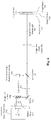
- FIG. 6 shows a three-wavelength, single-sensor embodiment that includes the image FOV-shifter (400), an objective lens (703), a three-wavelength illumination source (704) and associated beam splitter (705), an image lens (706) with auto-focus capability, for example a voltage-controlled liquid lens, and a single portrait-oriented image sensor (708).
- the image sensor is located at the midpoint of the focal range for ⁇ 2. Thus the system retains full autofocus range at ⁇ 2. However, autofocus range is reduced by the distance E2 at the other two wavelengths.
- FIG. 7 shows how the FOVs of the images (801, 802, 803) captured by the three-wavelength, single-sensor embodiment of FIG. 6 would cover the minimum microscope FOV (103), assuming the sensor is portrait-oriented and has a 4:3 aspect ratio.
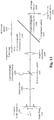
- FIG. 8 shows the embodiment of FIG. 6 modified by adding the optical path length equalizer (500) of FIG. 4 and by moving the image sensor (708) to the location that is at the midpoint of the autofocus range for all three-wavelengths.
- this embodiment enjoys full autofocus range at all three illumination wavelengths.
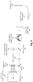
- FIG. 9 shows the embodiment of FIG. 6 modified by adding a wavelength separator (600) and two additional portrait-oriented image sensors (1002, 1006).
- all three image sensors (1002, 1006, 1010) are positioned relative to the wavelength separator to create equal optical path lengths (1004, 1008, 1012) at all three illumination wavelengths.
- the distance from the wavelength separator to the sensors used at ⁇ 1, ⁇ 2, and ⁇ 3 are E1, E2, and D respectively.
- E1 and E2 are the path length extensions needed to make the optical path lengths at ⁇ 1 and ⁇ 2 equal to the optical path length at ⁇ 3.
- Another advantage of the embodiment shown in FIG. 9 is that it allows the imaging system to operate with all illumination wavelengths active at the same time, which means that all three images can be captured simultaneously rather than sequentially, which can reduce the time required to capture all images.
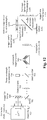
- FIG. 10 is the embodiment of FIG. 6 modified by replacing a single portrait-oriented sensor with one beam splitter (1101) and two landscape-oriented sensors (1103, 1106) in order to either create a larger microscope FOV or to increase image resolution, assuming the same type sensors are used in both embodiments.
- the two sensors are located on different image planes (1104, 1107), with the Top Sensor (1103) disposed to capture images of the top half of the minimum microscope FOV, and the Bottom Sensor (1106) disposed to capture images of the bottom half of the microscope FOV.
- FIG. 11 shows how the six images created by the three-wavelength, two-sensor embodiment of FIG. 10 would cover the minimum microscope FOV, assuming both sensors included in the embodiment are landscape-oriented and have a 4:3 aspect ratio. Note that the top row of three images (1201, 1202, 1203) is captured by "Top” sensor, while the bottom row of three images (1204, 1205, 1206) is captured by the "Bottom” sensor.
- FIG. 12 shows the embodiment of FIG. 10 modified by adding the optical path length equalizer (500) of FIG. 4 and by moving the two image sensors (1103, 1106) to locations that are at the midpoint of the autofocus range for all three wavelengths.
- this embodiment enjoys full autofocus range at all three illumination wavelengths.
- FIG. 13 shows a single-wavelength, two-sensor (1408, 1410) exemplary imaging system, not according to the invention, wherein two-sensors are located on two different image planes, and wherein both image planes (1409, 1411) are located at the midpoint of the autofocus range of the optical system.
- the illumination source (1402) can operate at more than one wavelength, for example to provide improved detect detection. However, this is not required for FOV shifting as it is in other embodiments.
- FIG. 14 shows how the FOVs of the two images captured by the example of FIG. 13 would cover the minimum microscope FOV (103), assuming both sensors (1501, 1502) have a landscape orientation and a 4:3 aspect ratio.
- FIG. 15 shows a single-wavelength, three-sensor (1601, 1602, 1604) exemplary imaging system, not according to the invention, wherein the three sensors are located on two different image planes (1603, 1605), and wherein both image planes are located at the midpoint (1406, 1407) of the autofocus range of the optical system.
- the illumination source can operate at more than one wavelength, for example to provide improved detect detection. However, this is not required for FOV shifting as it is in other embodiments.
- FIG. 16 shows how the FOVs of the images captured by the example of FIG. 15 would cover the minimum microscope FOV (103), assuming all three sensors (1701, 1702, 1703) have a portrait orientation and a 4:3 aspect ratio.
Landscapes
- Physics & Mathematics (AREA)
- General Physics & Mathematics (AREA)
- Optics & Photonics (AREA)
- Chemical & Material Sciences (AREA)
- Analytical Chemistry (AREA)
- Microscoopes, Condenser (AREA)
Claims (5)
- LWL-Steckverbinder-Bildgebungssystem mit Autofokusfunktion zur Überprüfung von Multifasersteckverbindern, umfassend:ein Gehäuse, das die optischen und elektrooptischen Komponenten des Bildgebungssystems enthält; eine Anschlusskonstruktion, um die Endfläche des zu überprüfenden Steckverbinders innerhalb des Autofokusbereichs des Bildgebungssystems während des Bildaufnahmevorgangs zu halten;eine Beleuchtungsquelle (704), die zu einem bestimmten Zeitpunkt bei einer von zwei oder mehr Wellenlängen funktionieren kann;einen Sichtfeld-Verschieber (400), der zwei dichroitische Strahlteiler (402, 405) und einen zusätzlichen Ablenkspiegel (408) umfasst, der dichroitisch oder breitbandig sein kann und vor der zu überprüfenden Endfläche angeordnet ist, wobei die dichroitischen Strahlteiler und der zusätzliche Ablenkspiegel im Strahlengang nacheinander positioniert sind, und jeder der dichroitischen Spiegel eine der von der Beleuchtungsquelle (704) erzeugten Wellenlängen reflektiert und die verbleibenden Wellenlängen durchlässt, so dass die aktuelle Beleuchtungswellenlänge bestimmt, welcher Endflächenabschnitt beleuchtet wird;ein optisches Autofokus-System, das eine oder mehrere Fixfokus- oder Autofokusobjektive umfasst;einen Bildstrahlteiler und zwei oder mehr Bildsensoren, die sich auf einer der beiden durch den Bildstrahlteiler erzeugten Bildebenen befinden;wobei der Bildstrahlteiler so konfiguriert ist, um das aktuelle Bild zu einem anderen Sensor zu lenken, abhängig davon, welche Beleuchtungswellenlänge aktiv ist.
- LWL-Steckverbinder-Bildgebungssystem mit Autofokusfunktion zur Überprüfung von Multifasersteckverbindern, umfassend:ein Gehäuse, das die optischen und elektrooptischen Komponenten des Bildgebungssystems enthält; eine Anschlusskonstruktion, um die Endfläche des zu überprüfenden Steckverbinders innerhalb des Autofokusbereichs des Bildgebungssystems während des Bildaufnahmevorgangs zu halten;eine Beleuchtungsquelle (704), die zu einem bestimmten Zeitpunkt bei einer von zwei oder mehr Wellenlängen funktionieren kann;einen Sichtfeld-Verschieber (400), der zwei dichroitische Strahlteiler (402, 405) und einen zusätzlichen Ablenkspiegel (408) umfasst, der dichroitisch oder breitbandig sein kann und vor der zu überprüfenden Endfläche angeordnet ist, wobei die dichroitischen Strahlteiler und der zusätzliche Ablenkspiegel im Strahlengang nacheinander positioniert sind, und jeder der dichroitischen Spiegel eine der von der Beleuchtungsquelle (704) erzeugten Wellenlängen reflektiert und die verbleibenden Wellenlängen durchlässt, so dass die aktuelle Beleuchtungswellenlänge bestimmt, welcher Endflächenabschnitt beleuchtet wird;ein optisches Autofokus-System, das eine oder mehrere Fixfokus- oder Autofokusobjektive umfasst;ein einzelner Bildsensor;wobei das Bildgebungssystem so angepasst ist, um ein Bild eines anderen Abschnitts der Endfläche des zu prüfenden Multifasersteckverbinders aufzunehmen, abhängig davon, welche Beleuchtungswellenlänge aktiv ist.
- Bildgebungssystem nach Anspruch 1 oder 2, ferner umfassend einen optischen Weglänge-Equalizer (500) vor dem optischen Autofokus-System, um zu ermöglichen, dass der Bildsensor am Mittelpunkt des Autofokusbereichs aller Beleuchtungswellenlängen angeordnet ist und somit den vollen Autofokusbereich des optischen Systems bei allen Beleuchtungswellenlängen beibehält.
- Bildgebungssystem nach Anspruch 1, wobei der Bildstrahlteiler aus einem Wellenlängentrenner (600) besteht und jeder der Bildsensoren relativ zum Wellenlängentrenner positioniert ist, um bei allen Beleuchtungswellenlängen die gleiche optische Weglänge zu erreichen und somit den vollen Autofokusbereich des optischen Systems bei allen Beleuchtungswellenlängen beizubehalten.
- Bildgebungssystem nach Anspruch 4, wobei alle Beleuchtungswellenlängun gleichzeitig aktiv sind, um zu ermöglichen, dass Bilder bei allen Wellenlängen gleichzeitig aufgenommen werden.
Applications Claiming Priority (1)
| Application Number | Priority Date | Filing Date | Title |
|---|---|---|---|
| PCT/IB2016/055913 WO2018065801A1 (en) | 2016-10-04 | 2016-10-04 | Imaging system for multi-fiber optic connector inspection |
Publications (2)
| Publication Number | Publication Date |
|---|---|
| EP3523618A1 EP3523618A1 (de) | 2019-08-14 |
| EP3523618B1 true EP3523618B1 (de) | 2021-02-17 |
Family
ID=57190206
Family Applications (1)
| Application Number | Title | Priority Date | Filing Date |
|---|---|---|---|
| EP16785266.4A Active EP3523618B1 (de) | 2016-10-04 | 2016-10-04 | Abbildungssystem zur inspektion von mehradrigen lichtwellenleiterverbindern |
Country Status (3)
| Country | Link |
|---|---|
| US (1) | US10627310B2 (de) |
| EP (1) | EP3523618B1 (de) |
| WO (1) | WO2018065801A1 (de) |
Families Citing this family (5)
| Publication number | Priority date | Publication date | Assignee | Title |
|---|---|---|---|---|
| US12135458B2 (en) | 2020-09-21 | 2024-11-05 | Panduit Corp. | Arrayed visual inspectors for fiber connectors and adapters |
| US12130197B2 (en) | 2020-11-27 | 2024-10-29 | Exfo Inc. | Optical fiber endface inspection microscope having a dual illumination source |
| US12449328B2 (en) | 2022-01-19 | 2025-10-21 | Panduit Corp. | Apparatus and system for visual inspection of fiber ends and image analysis tool for detecting contamination |
| US12429653B2 (en) * | 2022-05-11 | 2025-09-30 | Exfo Inc. | Adapter tip and microscope system for inspecting duplex fiber-optic connector endfaces |
| US20250314554A1 (en) * | 2024-04-08 | 2025-10-09 | Viavi Solutions Inc. | Facilitating inspection of structural features of an optical connector |
Family Cites Families (21)
| Publication number | Priority date | Publication date | Assignee | Title |
|---|---|---|---|---|
| US6381356B1 (en) * | 1996-10-23 | 2002-04-30 | Nec Corporation | Method and apparatus for inspecting high-precision patterns |
| DE19713362A1 (de) * | 1997-03-29 | 1998-10-01 | Zeiss Carl Jena Gmbh | Konfokale mikroskopische Anordnung |
| US6636658B2 (en) * | 2001-04-23 | 2003-10-21 | Optical Coating Laboratory, Inc. | Wavelength division multiplexing/demultiplexing systems |
| JP3797419B2 (ja) * | 2001-10-24 | 2006-07-19 | 株式会社東京精密 | 光コネクタ端面検査装置 |
| US6751017B2 (en) | 2002-03-19 | 2004-06-15 | Westover Scientific, Inc. | Microscope for backplane ribbon fiber analysis |
| US7239788B2 (en) | 2002-05-24 | 2007-07-03 | 4198638 Canada Inc. | Apparatus and method for inspecting optical fiber end face |
| US7079743B2 (en) * | 2004-10-13 | 2006-07-18 | Corning Cable Systems Llc | Apparatus and methods for estimating optical insertion loss |
| WO2008036468A2 (en) * | 2006-07-28 | 2008-03-27 | Em4, Inc. | System and method for built-in testing of a fiber optic transceiver |
| US7714996B2 (en) * | 2007-01-23 | 2010-05-11 | 3i Systems Corporation | Automatic inspection system for flat panel substrate |
| US7787112B2 (en) * | 2007-10-22 | 2010-08-31 | Visiongate, Inc. | Depth of field extension for optical tomography |
| US9492797B2 (en) * | 2008-09-23 | 2016-11-15 | Bio-Rad Laboratories, Inc. | System for detection of spaced droplets |
| US8104976B2 (en) | 2009-05-12 | 2012-01-31 | Lightel Technologies Inc. | Adaptive device for shifting imaging axis across fiber-optic endfaces in multi-fiber connector for inspection |
| US9841579B2 (en) * | 2013-09-27 | 2017-12-12 | Exfo Inc. | Multiple-fiber connector inspection |
| WO2015095169A1 (en) * | 2013-12-19 | 2015-06-25 | Corning Optical Communications LLC | Ferrule-core concentricity measurement systems and methods |
| CN105700123B (zh) * | 2014-12-15 | 2019-01-18 | 爱斯福公司 | 光纤检查显微镜与功率测量系统、光纤检查尖端及其使用方法 |
| JP2018514802A (ja) * | 2015-03-23 | 2018-06-07 | イースト カロライナ ユニバーシティ | 単一カメラを使用して遠隔物体を2つ以上のスペクトルチャネルで同時に画像化する為の多波長ビームスプリッタシステム |
| EP3430451A1 (de) * | 2016-03-17 | 2019-01-23 | Corning Optical Communications LLC | Abstimmbarer glasfaserverbinder und abstimmungsverfahren für glasfaserkabelanordnungen |
| US9841567B1 (en) * | 2016-08-16 | 2017-12-12 | Lightel Technologies, Inc. | Two-dimensional optical scanning method and optical scanning adapter for inspecting multiple-fiber optic connector |
| US10132808B2 (en) * | 2016-09-23 | 2018-11-20 | The United States Of America As Represented By Secretary Of The Navy | Method to detect/identify bacterial species using flow cytometry and surface enhanced Raman scattering |
| DE102016118898B4 (de) * | 2016-10-05 | 2022-03-17 | Ferdinand-Braun-Institut gGmbH, Leibniz- Institut für Höchstfrequenztechnik | Optisches System und Verfahren zur Spektroskopie |
| US10374700B2 (en) * | 2017-03-17 | 2019-08-06 | Fluke Corporation | Optical connector polarity and loss measurement using an integrating sphere-equipped optical measurement device |
-
2016
- 2016-10-04 US US15/575,726 patent/US10627310B2/en not_active Expired - Fee Related
- 2016-10-04 WO PCT/IB2016/055913 patent/WO2018065801A1/en not_active Ceased
- 2016-10-04 EP EP16785266.4A patent/EP3523618B1/de active Active
Non-Patent Citations (1)
| Title |
|---|
| None * |
Also Published As
| Publication number | Publication date |
|---|---|
| WO2018065801A1 (en) | 2018-04-12 |
| US10627310B2 (en) | 2020-04-21 |
| EP3523618A1 (de) | 2019-08-14 |
| US20190212227A1 (en) | 2019-07-11 |
Similar Documents
| Publication | Publication Date | Title |
|---|---|---|
| US10627310B2 (en) | Imaging system for multi-fiber connector inspection | |
| US6287020B1 (en) | Observation apparatus and fusion splicer for optical fibers | |
| US11644625B2 (en) | Adapter tip and microscope system for inspection of fiber-optic connector endfaces | |
| US10900866B2 (en) | Optical fiber endface inspection with optical power measurement | |
| US9915790B2 (en) | Fiber inspection microscope and power measurement system, fiber inspection tip and method using same | |
| CN104516059A (zh) | 多光纤连接器检查 | |
| US12429653B2 (en) | Adapter tip and microscope system for inspecting duplex fiber-optic connector endfaces | |
| CN105659127A (zh) | 复用的光电引擎 | |
| US20130038864A1 (en) | Fiber optic connector inspection microscope with integral optical power measurement | |
| JPH09288221A (ja) | リボン型光ファイバの突き合せ部を観察する方法及び観察装置 | |
| US20200012165A1 (en) | Toroidal micro lens array for use in a wavelength selective switch | |
| US8346084B2 (en) | Optical device with stable optical configuration | |
| JP2020501204A (ja) | 4つまたは5つのチャンネルをもつダイクロイックプリズムアセンブリ | |
| US12050149B2 (en) | Optical fiber endface inspection microscope having a swappable optical head | |
| US20030197791A1 (en) | Apparatus for inputting image and method of inputting the same | |
| Riza et al. | Fault-tolerant dense multiwavelength add–drop filter with a two-dimensional digital micromirror device | |
| TWI908298B (zh) | 用於測試光子積體電路的設備、測試卡及方法,以及光子積體電路 | |
| US12366672B2 (en) | Optical system and corresponding optical method | |
| JP2010181699A (ja) | レンズアダプタ | |
| US7277607B2 (en) | Optical multiplexer/demultiplexer, optical device, and optical transmission system | |
| US20250306352A1 (en) | Optical system to reorient a major dimension of a microscope’s field of view | |
| CN105264418B (zh) | 透镜装置 | |
| US20220229230A1 (en) | Optical Multiplexing Circuit and Light Source | |
| EP4278227B1 (de) | Mikroskopvorrichtung | |
| US20080193081A1 (en) | Microscope |
Legal Events
| Date | Code | Title | Description |
|---|---|---|---|
| STAA | Information on the status of an ep patent application or granted ep patent |
Free format text: STATUS: UNKNOWN |
|
| STAA | Information on the status of an ep patent application or granted ep patent |
Free format text: STATUS: THE INTERNATIONAL PUBLICATION HAS BEEN MADE |
|
| PUAI | Public reference made under article 153(3) epc to a published international application that has entered the european phase |
Free format text: ORIGINAL CODE: 0009012 |
|
| STAA | Information on the status of an ep patent application or granted ep patent |
Free format text: STATUS: REQUEST FOR EXAMINATION WAS MADE |
|
| 17P | Request for examination filed |
Effective date: 20190205 |
|
| AK | Designated contracting states |
Kind code of ref document: A1 Designated state(s): AL AT BE BG CH CY CZ DE DK EE ES FI FR GB GR HR HU IE IS IT LI LT LU LV MC MK MT NL NO PL PT RO RS SE SI SK SM TR |
|
| AX | Request for extension of the european patent |
Extension state: BA ME |
|
| DAV | Request for validation of the european patent (deleted) | ||
| DAX | Request for extension of the european patent (deleted) | ||
| STAA | Information on the status of an ep patent application or granted ep patent |
Free format text: STATUS: EXAMINATION IS IN PROGRESS |
|
| 17Q | First examination report despatched |
Effective date: 20200512 |
|
| GRAP | Despatch of communication of intention to grant a patent |
Free format text: ORIGINAL CODE: EPIDOSNIGR1 |
|
| STAA | Information on the status of an ep patent application or granted ep patent |
Free format text: STATUS: GRANT OF PATENT IS INTENDED |
|
| INTG | Intention to grant announced |
Effective date: 20201112 |
|
| RIN1 | Information on inventor provided before grant (corrected) |
Inventor name: GAVRILINAS, NIKOLAJUS Inventor name: LEVIN, PIOTR ANATOLIJ |
|
| GRAS | Grant fee paid |
Free format text: ORIGINAL CODE: EPIDOSNIGR3 |
|
| GRAA | (expected) grant |
Free format text: ORIGINAL CODE: 0009210 |
|
| STAA | Information on the status of an ep patent application or granted ep patent |
Free format text: STATUS: THE PATENT HAS BEEN GRANTED |
|
| AK | Designated contracting states |
Kind code of ref document: B1 Designated state(s): AL AT BE BG CH CY CZ DE DK EE ES FI FR GB GR HR HU IE IS IT LI LT LU LV MC MK MT NL NO PL PT RO RS SE SI SK SM TR |
|
| REG | Reference to a national code |
Ref country code: GB Ref legal event code: FG4D |
|
| REG | Reference to a national code |
Ref country code: CH Ref legal event code: EP |
|
| REG | Reference to a national code |
Ref country code: DE Ref legal event code: R096 Ref document number: 602016052652 Country of ref document: DE |
|
| REG | Reference to a national code |
Ref country code: AT Ref legal event code: REF Ref document number: 1362062 Country of ref document: AT Kind code of ref document: T Effective date: 20210315 |
|
| REG | Reference to a national code |
Ref country code: IE Ref legal event code: FG4D |
|
| REG | Reference to a national code |
Ref country code: LT Ref legal event code: MG9D |
|
| REG | Reference to a national code |
Ref country code: NL Ref legal event code: MP Effective date: 20210217 |
|
| PG25 | Lapsed in a contracting state [announced via postgrant information from national office to epo] |
Ref country code: LT Free format text: LAPSE BECAUSE OF FAILURE TO SUBMIT A TRANSLATION OF THE DESCRIPTION OR TO PAY THE FEE WITHIN THE PRESCRIBED TIME-LIMIT Effective date: 20210217 Ref country code: BG Free format text: LAPSE BECAUSE OF FAILURE TO SUBMIT A TRANSLATION OF THE DESCRIPTION OR TO PAY THE FEE WITHIN THE PRESCRIBED TIME-LIMIT Effective date: 20210517 Ref country code: GR Free format text: LAPSE BECAUSE OF FAILURE TO SUBMIT A TRANSLATION OF THE DESCRIPTION OR TO PAY THE FEE WITHIN THE PRESCRIBED TIME-LIMIT Effective date: 20210518 Ref country code: FI Free format text: LAPSE BECAUSE OF FAILURE TO SUBMIT A TRANSLATION OF THE DESCRIPTION OR TO PAY THE FEE WITHIN THE PRESCRIBED TIME-LIMIT Effective date: 20210217 Ref country code: HR Free format text: LAPSE BECAUSE OF FAILURE TO SUBMIT A TRANSLATION OF THE DESCRIPTION OR TO PAY THE FEE WITHIN THE PRESCRIBED TIME-LIMIT Effective date: 20210217 Ref country code: PT Free format text: LAPSE BECAUSE OF FAILURE TO SUBMIT A TRANSLATION OF THE DESCRIPTION OR TO PAY THE FEE WITHIN THE PRESCRIBED TIME-LIMIT Effective date: 20210617 Ref country code: NO Free format text: LAPSE BECAUSE OF FAILURE TO SUBMIT A TRANSLATION OF THE DESCRIPTION OR TO PAY THE FEE WITHIN THE PRESCRIBED TIME-LIMIT Effective date: 20210517 |
|
| REG | Reference to a national code |
Ref country code: AT Ref legal event code: MK05 Ref document number: 1362062 Country of ref document: AT Kind code of ref document: T Effective date: 20210217 |
|
| PG25 | Lapsed in a contracting state [announced via postgrant information from national office to epo] |
Ref country code: SE Free format text: LAPSE BECAUSE OF FAILURE TO SUBMIT A TRANSLATION OF THE DESCRIPTION OR TO PAY THE FEE WITHIN THE PRESCRIBED TIME-LIMIT Effective date: 20210217 Ref country code: PL Free format text: LAPSE BECAUSE OF FAILURE TO SUBMIT A TRANSLATION OF THE DESCRIPTION OR TO PAY THE FEE WITHIN THE PRESCRIBED TIME-LIMIT Effective date: 20210217 Ref country code: LV Free format text: LAPSE BECAUSE OF FAILURE TO SUBMIT A TRANSLATION OF THE DESCRIPTION OR TO PAY THE FEE WITHIN THE PRESCRIBED TIME-LIMIT Effective date: 20210217 Ref country code: NL Free format text: LAPSE BECAUSE OF FAILURE TO SUBMIT A TRANSLATION OF THE DESCRIPTION OR TO PAY THE FEE WITHIN THE PRESCRIBED TIME-LIMIT Effective date: 20210217 Ref country code: RS Free format text: LAPSE BECAUSE OF FAILURE TO SUBMIT A TRANSLATION OF THE DESCRIPTION OR TO PAY THE FEE WITHIN THE PRESCRIBED TIME-LIMIT Effective date: 20210217 |
|
| PG25 | Lapsed in a contracting state [announced via postgrant information from national office to epo] |
Ref country code: IS Free format text: LAPSE BECAUSE OF FAILURE TO SUBMIT A TRANSLATION OF THE DESCRIPTION OR TO PAY THE FEE WITHIN THE PRESCRIBED TIME-LIMIT Effective date: 20210617 |
|
| PG25 | Lapsed in a contracting state [announced via postgrant information from national office to epo] |
Ref country code: AT Free format text: LAPSE BECAUSE OF FAILURE TO SUBMIT A TRANSLATION OF THE DESCRIPTION OR TO PAY THE FEE WITHIN THE PRESCRIBED TIME-LIMIT Effective date: 20210217 Ref country code: SM Free format text: LAPSE BECAUSE OF FAILURE TO SUBMIT A TRANSLATION OF THE DESCRIPTION OR TO PAY THE FEE WITHIN THE PRESCRIBED TIME-LIMIT Effective date: 20210217 Ref country code: CZ Free format text: LAPSE BECAUSE OF FAILURE TO SUBMIT A TRANSLATION OF THE DESCRIPTION OR TO PAY THE FEE WITHIN THE PRESCRIBED TIME-LIMIT Effective date: 20210217 Ref country code: EE Free format text: LAPSE BECAUSE OF FAILURE TO SUBMIT A TRANSLATION OF THE DESCRIPTION OR TO PAY THE FEE WITHIN THE PRESCRIBED TIME-LIMIT Effective date: 20210217 |
|
| REG | Reference to a national code |
Ref country code: DE Ref legal event code: R097 Ref document number: 602016052652 Country of ref document: DE |
|
| PG25 | Lapsed in a contracting state [announced via postgrant information from national office to epo] |
Ref country code: DK Free format text: LAPSE BECAUSE OF FAILURE TO SUBMIT A TRANSLATION OF THE DESCRIPTION OR TO PAY THE FEE WITHIN THE PRESCRIBED TIME-LIMIT Effective date: 20210217 Ref country code: RO Free format text: LAPSE BECAUSE OF FAILURE TO SUBMIT A TRANSLATION OF THE DESCRIPTION OR TO PAY THE FEE WITHIN THE PRESCRIBED TIME-LIMIT Effective date: 20210217 Ref country code: SK Free format text: LAPSE BECAUSE OF FAILURE TO SUBMIT A TRANSLATION OF THE DESCRIPTION OR TO PAY THE FEE WITHIN THE PRESCRIBED TIME-LIMIT Effective date: 20210217 |
|
| PLBE | No opposition filed within time limit |
Free format text: ORIGINAL CODE: 0009261 |
|
| STAA | Information on the status of an ep patent application or granted ep patent |
Free format text: STATUS: NO OPPOSITION FILED WITHIN TIME LIMIT |
|
| 26N | No opposition filed |
Effective date: 20211118 |
|
| PG25 | Lapsed in a contracting state [announced via postgrant information from national office to epo] |
Ref country code: AL Free format text: LAPSE BECAUSE OF FAILURE TO SUBMIT A TRANSLATION OF THE DESCRIPTION OR TO PAY THE FEE WITHIN THE PRESCRIBED TIME-LIMIT Effective date: 20210217 Ref country code: ES Free format text: LAPSE BECAUSE OF FAILURE TO SUBMIT A TRANSLATION OF THE DESCRIPTION OR TO PAY THE FEE WITHIN THE PRESCRIBED TIME-LIMIT Effective date: 20210217 |
|
| PG25 | Lapsed in a contracting state [announced via postgrant information from national office to epo] |
Ref country code: SI Free format text: LAPSE BECAUSE OF FAILURE TO SUBMIT A TRANSLATION OF THE DESCRIPTION OR TO PAY THE FEE WITHIN THE PRESCRIBED TIME-LIMIT Effective date: 20210217 |
|
| PG25 | Lapsed in a contracting state [announced via postgrant information from national office to epo] |
Ref country code: IT Free format text: LAPSE BECAUSE OF FAILURE TO SUBMIT A TRANSLATION OF THE DESCRIPTION OR TO PAY THE FEE WITHIN THE PRESCRIBED TIME-LIMIT Effective date: 20210217 |
|
| REG | Reference to a national code |
Ref country code: DE Ref legal event code: R119 Ref document number: 602016052652 Country of ref document: DE |
|
| PG25 | Lapsed in a contracting state [announced via postgrant information from national office to epo] |
Ref country code: IS Free format text: LAPSE BECAUSE OF FAILURE TO SUBMIT A TRANSLATION OF THE DESCRIPTION OR TO PAY THE FEE WITHIN THE PRESCRIBED TIME-LIMIT Effective date: 20210617 |
|
| REG | Reference to a national code |
Ref country code: CH Ref legal event code: PL |
|
| REG | Reference to a national code |
Ref country code: BE Ref legal event code: MM Effective date: 20211031 |
|
| PG25 | Lapsed in a contracting state [announced via postgrant information from national office to epo] |
Ref country code: MC Free format text: LAPSE BECAUSE OF FAILURE TO SUBMIT A TRANSLATION OF THE DESCRIPTION OR TO PAY THE FEE WITHIN THE PRESCRIBED TIME-LIMIT Effective date: 20210217 |
|
| PG25 | Lapsed in a contracting state [announced via postgrant information from national office to epo] |
Ref country code: LU Free format text: LAPSE BECAUSE OF NON-PAYMENT OF DUE FEES Effective date: 20211004 Ref country code: DE Free format text: LAPSE BECAUSE OF NON-PAYMENT OF DUE FEES Effective date: 20220503 Ref country code: BE Free format text: LAPSE BECAUSE OF NON-PAYMENT OF DUE FEES Effective date: 20211031 |
|
| PG25 | Lapsed in a contracting state [announced via postgrant information from national office to epo] |
Ref country code: LI Free format text: LAPSE BECAUSE OF NON-PAYMENT OF DUE FEES Effective date: 20211031 Ref country code: CH Free format text: LAPSE BECAUSE OF NON-PAYMENT OF DUE FEES Effective date: 20211031 |
|
| PG25 | Lapsed in a contracting state [announced via postgrant information from national office to epo] |
Ref country code: FR Free format text: LAPSE BECAUSE OF NON-PAYMENT OF DUE FEES Effective date: 20211031 |
|
| PG25 | Lapsed in a contracting state [announced via postgrant information from national office to epo] |
Ref country code: IE Free format text: LAPSE BECAUSE OF NON-PAYMENT OF DUE FEES Effective date: 20211004 |
|
| PG25 | Lapsed in a contracting state [announced via postgrant information from national office to epo] |
Ref country code: CY Free format text: LAPSE BECAUSE OF FAILURE TO SUBMIT A TRANSLATION OF THE DESCRIPTION OR TO PAY THE FEE WITHIN THE PRESCRIBED TIME-LIMIT Effective date: 20210217 |
|
| PG25 | Lapsed in a contracting state [announced via postgrant information from national office to epo] |
Ref country code: HU Free format text: LAPSE BECAUSE OF FAILURE TO SUBMIT A TRANSLATION OF THE DESCRIPTION OR TO PAY THE FEE WITHIN THE PRESCRIBED TIME-LIMIT; INVALID AB INITIO Effective date: 20161004 |
|
| PG25 | Lapsed in a contracting state [announced via postgrant information from national office to epo] |
Ref country code: MK Free format text: LAPSE BECAUSE OF FAILURE TO SUBMIT A TRANSLATION OF THE DESCRIPTION OR TO PAY THE FEE WITHIN THE PRESCRIBED TIME-LIMIT Effective date: 20210217 |
|
| PG25 | Lapsed in a contracting state [announced via postgrant information from national office to epo] |
Ref country code: TR Free format text: LAPSE BECAUSE OF FAILURE TO SUBMIT A TRANSLATION OF THE DESCRIPTION OR TO PAY THE FEE WITHIN THE PRESCRIBED TIME-LIMIT Effective date: 20210217 |
|
| PG25 | Lapsed in a contracting state [announced via postgrant information from national office to epo] |
Ref country code: MT Free format text: LAPSE BECAUSE OF FAILURE TO SUBMIT A TRANSLATION OF THE DESCRIPTION OR TO PAY THE FEE WITHIN THE PRESCRIBED TIME-LIMIT Effective date: 20210217 |
|
| PGFP | Annual fee paid to national office [announced via postgrant information from national office to epo] |
Ref country code: GB Payment date: 20250808 Year of fee payment: 10 |