EP3523724B1 - Gestion de ressources de couche de service pour interfonctionnement et extensibilité génériques - Google Patents
Gestion de ressources de couche de service pour interfonctionnement et extensibilité génériques Download PDFInfo
- Publication number
- EP3523724B1 EP3523724B1 EP17790903.3A EP17790903A EP3523724B1 EP 3523724 B1 EP3523724 B1 EP 3523724B1 EP 17790903 A EP17790903 A EP 17790903A EP 3523724 B1 EP3523724 B1 EP 3523724B1
- Authority
- EP
- European Patent Office
- Prior art keywords
- resource
- service layer
- definition
- resources
- document
- Prior art date
- Legal status (The legal status is an assumption and is not a legal conclusion. Google has not performed a legal analysis and makes no representation as to the accuracy of the status listed.)
- Active
Links
Images





Classifications
-
- H—ELECTRICITY
- H04—ELECTRIC COMMUNICATION TECHNIQUE
- H04L—TRANSMISSION OF DIGITAL INFORMATION, e.g. TELEGRAPHIC COMMUNICATION
- H04L41/00—Arrangements for maintenance, administration or management of data switching networks, e.g. of packet switching networks
- H04L41/02—Standardisation; Integration
-
- H—ELECTRICITY
- H04—ELECTRIC COMMUNICATION TECHNIQUE
- H04L—TRANSMISSION OF DIGITAL INFORMATION, e.g. TELEGRAPHIC COMMUNICATION
- H04L67/00—Network arrangements or protocols for supporting network services or applications
- H04L67/50—Network services
- H04L67/51—Discovery or management thereof, e.g. service location protocol [SLP] or web services
-
- G—PHYSICS
- G06—COMPUTING OR CALCULATING; COUNTING
- G06F—ELECTRIC DIGITAL DATA PROCESSING
- G06F9/00—Arrangements for program control, e.g. control units
- G06F9/06—Arrangements for program control, e.g. control units using stored programs, i.e. using an internal store of processing equipment to receive or retain programs
- G06F9/46—Multiprogramming arrangements
- G06F9/50—Allocation of resources, e.g. of the central processing unit [CPU]
- G06F9/5061—Partitioning or combining of resources
-
- H—ELECTRICITY
- H04—ELECTRIC COMMUNICATION TECHNIQUE
- H04L—TRANSMISSION OF DIGITAL INFORMATION, e.g. TELEGRAPHIC COMMUNICATION
- H04L67/00—Network arrangements or protocols for supporting network services or applications
- H04L67/14—Session management
- H04L67/141—Setup of application sessions
-
- H—ELECTRICITY
- H04—ELECTRIC COMMUNICATION TECHNIQUE
- H04L—TRANSMISSION OF DIGITAL INFORMATION, e.g. TELEGRAPHIC COMMUNICATION
- H04L67/00—Network arrangements or protocols for supporting network services or applications
- H04L67/14—Session management
- H04L67/146—Markers for unambiguous identification of a particular session, e.g. session cookie or URL-encoding
-
- H—ELECTRICITY
- H04—ELECTRIC COMMUNICATION TECHNIQUE
- H04L—TRANSMISSION OF DIGITAL INFORMATION, e.g. TELEGRAPHIC COMMUNICATION
- H04L67/00—Network arrangements or protocols for supporting network services or applications
- H04L67/50—Network services
- H04L67/53—Network services using third party service providers
-
- H—ELECTRICITY
- H04—ELECTRIC COMMUNICATION TECHNIQUE
- H04L—TRANSMISSION OF DIGITAL INFORMATION, e.g. TELEGRAPHIC COMMUNICATION
- H04L69/00—Network arrangements, protocols or services independent of the application payload and not provided for in the other groups of this subclass
- H04L69/30—Definitions, standards or architectural aspects of layered protocol stacks
- H04L69/32—Architecture of open systems interconnection [OSI] 7-layer type protocol stacks, e.g. the interfaces between the data link level and the physical level
- H04L69/322—Intralayer communication protocols among peer entities or protocol data unit [PDU] definitions
- H04L69/329—Intralayer communication protocols among peer entities or protocol data unit [PDU] definitions in the application layer [OSI layer 7]
Definitions
- one mechanism disclosed herein comprises defining a new service layer (SL) resource definition registration procedure that allows for specifying custom attributes of service layer resources to represent third party technology resources.
- SL service layer
- additional procedures are introduced for managing the resource definitions.
- a third mechanism disclosed herein comprises defining a SL generic interworking procedure to intelligently retarget requests toward interworked resources based on the retargeting indicator provided by the data model mapping.
- Interworking refers to the workings of an external technology within the domain of a second technology.
- LWM2M may be interworked into oneM2M.
- interworking entails some form of protocol translation and data model mapping between the two technologies.
- LWM2M is considered a third party technology that is interworked with the SL architecture. It is a lightweight client-server protocol defined for use in device management and service enablement of devices, which are typically constrained in nature with limited processing (CPU, MCU) and storage (RAM, ROM) capabilities.
- Resource activation is a SL process in which a resource definition is made available to be used by a service layer.
- the process may include authenticating the requestor, extracting information from a resource definition document to create a schema document for the resource/resource type, updating supported resource type attributes for discovery purposes, etc.
- Resource deactivation is a SL process to remove a schema document from a SL repository so future resources based on the removed schema cannot be created. This process is only performed if a resource type is no longer in use and is being retired.
- a resource definition is a document that describes in detail a service layer resource type.
- the document includes information such as the resource type, the name of the specialized resource type if one exists (e.g., in oneM2M, battery is a specialization of the mgmtObj resource type), version number, where in the resource tree instances of the resource can be created, the attributes of the resource instance, activation procedures, etc.
- a resource instance is an entry in a service layer resource tree that corresponds to a resource type. Attributes of the instance will contain data pertinent to the purpose it was created for.
- a resource type denotes a purpose for the resource, such as for an application, a container, or a subscription resource.
- Retargeting is the process in which a request to a SL resource or attribute at one SL entity A (e.g., a server) is redirected to another entity B (e.g., a device) where the requested information resides.
- entity A e.g., a server
- entity B e.g., a device
- the SL at entity A in this case acts as a transport mechanism between the requestor and another entity B (e.g., the device).
- a resource schema is a template for specifying the contents of a resource type.
- An XML Schema Definition (XSD) is an example of a resource schema document in Extensible Markup Language (XML) format.
- An XSD describes the structure of an XML document by showing the elements and attributes that can appear in the document, the number and order of the child elements, the associated data types, and possibly default or fixed values for the elements/attributes.
- each resource type has a corresponding XSD that shows how the resource should be constructed and what information is contained in the resource.
- An M2M/IoT Service Layer is a technology specifically targeted towards providing value-added services for M2M/IoT devices and applications.
- a global standard body such as oneM2M is developing M2M/IoT SLs to address the challenges associated with the integration of M2M/IoT devices and applications into deployments with the Internet/Web, cellular, enterprise, and home networks, as demonstrated in TS-0001 oneM2M Functional Architecture, V-2.10.0.
- An example of oneM2M SL architecture is shown in FIG. 1 , which depicts various reference points associated with a Common Services Entity (CSE).
- the Mca interface provides service layer access to Application Entities (AEs), while the Mcc and Mcc' reference points allows for CSE to CSE communications.
- the Mcn interface provides access to the underlying network technology.
- the oneM2M architecture also provides the capability to interwork with non oneM2M technologies, as shown in FIG. 1 .
- These interworked devices are also referred to as Non-oneM2M Device Nodes (NoDN) and their inclusion in the architecture is one key reason oneM2M can truly claim it is a horizontal platform that can interoperate with all vertical markets.
- NoDN Non-oneM2M Device Nodes
- An M2M/IoT SL can provide applications and devices access to a collection of M2M/IoT oriented capabilities.
- M2M/IoT oriented capabilities include security, charging, data management, device management, discovery, provisioning, and connectivity management.
- APIs Application Programming Interfaces
- resource management provides the means for applications and devices to communicate with each other.
- a resource has attributes and child resources to provide data exchanges between entities.
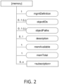
- FIG. 2 shows an example oneM2M resource in which the oval shapes represent attributes and the rectangular shapes (e.g., ⁇ subscription >) represent a child resource.
- the attributes specify the data model of the corresponding resource (e.g., memAvailable and memTotal ) and may also include meta-data that offers additional information, such as mgmtDefinition and description attributes of the resource.
- Resources may have defined attributes and child resources that are specified by the standard.
- the standard has defined what resources and attributes are, the data types supported, where in the resource tree a particular resource belongs, the multiplicity of certain resources or attributes, the schema document that describes the resource type, XSD validation performed during the creation of a resource, etc.
- resource management Collectively, the semantics of the resource and the procedures used to manage access to the resource is referred to as resource management.
- ⁇ mgmtObj> and ⁇ flexContainer> resources allow for defining specializations of the corresponding generic resources. In other words, these resources allow for defining custom attributes of either the ⁇ mgmtObj> or ⁇ flexContainer> resource for specialized functionality not found in other oneM2M resources.
- ⁇ mgmtObj> resources may require standardized mappings to the underlying technologies as discussed in TS-0004 Service Layer Core Protocol, V-2.5.0, and TS-0006 Management Enablement (BBF), V-1.1.4.
- ⁇ flexContainer> resources contain a containerDefinition attribute in which a link or Uniform Resource Indicator (URI) to the schema of the resource is provided to the service layer. However, no procedure is currently defined to describe what the service layer does with the attribute.
- URI Uniform Resource Indicator
- the order of all attributes and for each one its multiplicity, whether it is mandatory or optional, and the associated data type are all provided by the XSD document.
- the XSD document defines information the SL needs for managing the resource and exposing it to applications interested in accessing the resource.
- SL interworking is a key component that enables the SL architecture to be a horizontal platform for all vertical markets. Exemplary interworking configurations within oneM2M are shown in FIG. 4 .
- an Interworking Proxy Entity IPE
- a component of the translation involves the mapping of oneM2M resources to non-oneM2M data models and vice versa.
- the IPE is typically realized as a oneM2M AE that interfaces to a CSE using the Mca interface.
- the IPE has a non-oneM2M interface that communicates to the interworked entity through its native protocol.
- Three forms of oneM2M interworking are specified by TS-0001. These include interworking with full mapping of the semantic of the non-oneM2M data model to Mca, interworking using containers for transparent transport of encoded non-oneM2M data and commands via Mca, and interworking using a retargeting mechanism via AE or CSE resources.
- Full mapping of the semantic of non-oneM2M data model interworking involves an IPE or AE to map one-to-one the resources of an interworked device into appropriate oneM2M resources and attributes. For example, for a device with temperature, humidity, and light sensors, an IPE or AE will create three oneM2M resources to each represent the individual sensor. This is considered a full mapping. As a result, a manual process is undertaken during the design of the IPE/AE to support devices for interworking. This process is required for each new device that is interworked to the service layer.
- Transparent interworking involves encapsulating non-oneM2M data models within oneM2M container resources and requiring AEs to encode and decode the data. This tunneling of information within oneM2M resources is inefficient and pushes the complexity to the AEs. As a result, only AEs with the required knowledge of the underlying data model and protocol may use the data encapsulated in the container resources.
- Retargeting interworking on the other hand, completely bypasses the majority of functionalities the service layer offers.
- an AE or CSE provides a mapped interface of oneM2M resources and when a resource is accessed, the operation will be retargeted to the IPE. In this case, no insight into the contents of the data model is provided.
- ⁇ mgmtObj> resources are standardized oneM2M resources that represent data models of the underlying device management (DM) technology, and AEs access these ⁇ mgmtObj> resources to manage the devices.
- DM device management
- the Lightweight M2M (LWM2M) protocol is based on a client-server architecture that features a simple and flat resource structure that is more applicable to constrained devices. Additional information on the LWM2M protocol may be found in Open Mobile Alliance (OMA) Lightweight Machine to Machine Technical Specification, Version 1.0.
- OMA Open Mobile Alliance
- the resource tree is defined as LWM2M Objects with underlying resources organized in a flat structure with few levels of hierarchies.
- the definitions of Objects and resources in LWM2M are mapped respectively to that of resources and attributes in oneM2M architecture.
- An exemplary LWM2M architecture is shown in FIG. 5 .
- the LWM2M Protocol In addition to supporting device management, the LWM2M Protocol also supports service enablement provided by the constrained devices. Since constrained devices mostly provide data measurements for particular applications, information reporting is the main service enablement specified in the protocol. As such, the design of the Objects focuses on providing resources that will support device management and information reporting.
- FIG. 6 shows an example service layer deployment scenario in which a service layer (e.g., oneM2M server) supports LWM2M interworking.
- the service layer supports the LWM2M Objects specified in TS-0001, the TS-0005 Management Enablement (OMA), V-1.4.1, and OMA LWM2M Technical Specification.
- OMA Management Enablement
- FIG. 6 Customer1 initially deploys Device1 which supports the LWM2M Objects defined in the OMA LWM2M Technical Specification, and App1 is used to manage Device1.
- Device1 is updated with some extended LWM2M Objects such as LockWipe and Connectivity Management objects that were not defined in TS-0001 or TS-0005.
- Customer2 wants to consolidate its operations since it is managing devices from two different technologies, for example, oneM2M and the Open Internet Consortium (OIC). Customer2 already uses App2 to manage its service layer devices and would like to migrate its OIC devices into the service layer. This way, Customer2 will be able to only use App2 to manage all of its devices. Similar to the LWM2M scenario described above, Customer2 is not able to manage Device3 using the service layer as this OIC device is not supported.
- OIC Open Internet Consortium
- oneM2M defines resource mappings for data models of interworked technologies such as, for example, LWM2M (as described in TS-0014 TWM2M Interworking, V-0.13.0), AllJoyn (as described in TS-0021 oneM2M and AllJoyn Interworking, V-0.3.0), and OIC (as described in TS-0024 OIC Interworking, V-0.4.0) in an abstract way.
- LWM2M as described in TS-0014 TWM2M Interworking, V-0.13.0
- AllJoyn as described in TS-0021 oneM2M and AllJoyn Interworking, V-0.3.0
- OIC as described in TS-0024 OIC Interworking, V-0.4.0
- the LWM2M Firmware Update Object does not have all its resources mapped to oneM2M [firmware] attributes. As shown in FIG. 7 , the LWM2M Device Object is mapped to four different oneM2M ⁇ mgmtObj>s. Finally, the LWM2M Connectivity Monitoring and Connectivity Status Objects are not even mapped to oneM2M resources.
- a CSE or an AE resource is typically created to represent the interworked entity and requests to the resource are retargeted to the IPE.
- FIG. 6 highlights the lack of support for an important feature of a horizontal service layer platform such as oneM2M - the ability to efficiently and dynamically support vendor specific data models.
- the oneM2M standard already provides resources that could be customized, e.g. ⁇ mgmtObj> and ⁇ flexContainer> resources, to support interworking.
- resources that could be customized, e.g. ⁇ mgmtObj> and ⁇ flexContainer> resources, to support interworking.
- oneM2M currently lacks a procedure to take advantage of the ability to customize resource attributes dynamically.
- These vendor specific resources are critical for vendors from the same vertical markets to differentiate their product offerings and show the value-add of their platform. When expanded to include vendors from different vertical markets, the benefits of such a dynamic interworking mechanism are magnified.
- a resource definition document describes a resource type similar to how a resource type is defined in a standard specification. For example, a oneM2M ⁇ AE> is described in TS-0001 in which the AE's attributes and child resources are listed, what common attributes it has, where in the resource tree it exists, the multiplicity of its attributes and child resources with the corresponding data types, etc.
- protocol bindings are provided in TS-0004 in which the following may be specified: data types and XSD or schema files, short names used, optionality of primitive attributes, procedures for access to the resource, etc. All of this information is contained in the resource definition document, which also includes additional instructions for how the service layer should activate the resource definition to enable it for use.
- a data model mapping document may be used to provide one-to-one mapping of third party resources to service layer resource attributes. As a result, it resembles portions of a schema file that describe the resource specific attributes. This document provides mappings of service layer resource attributes to third party resources such as those provided in TS-0005 for LWM2M. This information is used during protocol translation.
- the data model mapping document includes a retargeting indicator for each resource attribute to direct the service layer on when to retarget retrieve requests to minimize messaging traffic.
- an IPE is first provisioned with a new resource definition for an interworked device.
- This resource definition is then registered to a service layer, which adds the management of the new resource to the service layer's operation.
- a data model mapping is provisioned to the IPE in which the data model of the interworked device is mapped to SL resource attributes.
- This data model mapping is also registered to the service layer to provide retargeting indicators for optimizing messaging to interworked resources.
- the interworked device is then registered or provisioned to the IPE, which in turn registers the device to the service layer.
- a LWM2M device registers to a LWM2M server, which is part of the IPE, and the IPE will then registers the device to the service layer.
- FIG. 8 shows an IPE registering both the resource definition and data model mapping documents to the service layer.
- a managing SL application or server administrator could also register these documents to the service layer instead of the IPE.
- the terms IPE, managing SL application, and service layer administrator may be used interchangeably.
- an application can use the service layer's resource discovery procedure to find the new interworked device resource.
- the application then makes a request targeting the interworked resource, and the service layer evaluates the criteria of the interworked retargeting indicator to make a determination on whether to initiate a generic interworking procedure. If initiated, the service layer retargets the application's request to the IPE, which performs the generic interworking mapping from the SL protocol to the native interworked device's protocol. Note that some SL requests may not be retargeted to the IPE if the requested data is static in nature. However, at least one retargeted request is required to retrieve the static data.
- the response returned from the interworked device is relayed from the IPE, to the service layer, and finally to the application.
- the service layer may cache the response dependent on the retargeting indicator.
- a resource definition is defined to provide a one-to-one mapping from interworked device resources to SL resources and attributes.
- the resource definition essentially reflects the same work performed during standardization in which a resource type is defined, the name given to a specialized resource type if one exists, the attributes and child resources for the resource type, a schema document to describe the resource for use in validation the creation of the resource, and other information and procedures to manage the resource.
- the information required for a resource definition is captured in a document that is then provisioned to an IPE, a managing application, or a server administrator for registration into the service layer using the ideas in this paper.
- the one-to-one mapping consists of two steps: identifying the native data model required to access and/or manage the device and mapping the device's native data model to service layer resources and attributes.
- the result of the mapping will generate both a SL resource definition document and a data model mapping document.
- the resource definition document is provided to the SL for defining new resources or resource types, that is, defining new custom resources or custom resource types, while the data model mapping document is provided to the SL for interworking.
- the data model mapping document provides retargeting indicators to tell when a service layer should retarget requests for a resource.
- the IPE uses the data model mapping document for both protocol translation and retargeting. Protocol translation may involve creating a new message that the interworked device understands. Retargeting may involve the IPE communicating with the interworked device to get a response to return to the service layer.
- the documents are provisioned to the IPE to initiate the corresponding registrations to the service layer.
- the IPE will first register the resource definition to the service layer. This registration is different than current SL registration as it is registering a new resource definition rather than requesting the SL to create a new instance of a SL resource.
- the target URI of the registration request is to a virtual resource, which signifies to the SL that a resource definition is being registered.
- the purpose of targeting a virtual resource instead of a normal SL resource is to inform the service layer that the registration operation is outside the normal mode of operation and no resource instance is being created in the resource tree.
- a new service layer resource can also be created in the resource tree to host all the resource definitions the service layer supports.
- the target URI of the registration request will target the new SL resource.
- a new "resourceDefinitions" resource could be created in the SL resource tree to store all the resource definitions.
- the target URI could be in the form of, for example, "/ resourceDefinitions " or "/ ⁇ SL_name> / resourceDefinitions ".
- the resource definition must contain two extra attributes that a resource definition using the virtual resource approach will not have: activate and deactivate. These attributes will be utilized to enable the use of the resource definition as described below.
- FIG. 9 shows an exemplary resource definition registration procedure that the IPE makes to the service layer, as discussed below.
- step 1 after the IPE is provisioned with the resource definition document of the interworked device, it registers the document to the service layer.
- the IPE targets a virtual resource to indicate the registration is one for a resource definition.
- An example URI for the virtual resource could be in the form of: / ⁇ SL_name> / resourceDefinitions.
- Included in the request is the resource definition document for the interworked device. This document will include information the service layer needs to manage the resource and expose it for resource discovery. Table 1 shows the different components that make up the resource definition document. The information provided will enable the service layer to extract a oneM2M XSD document from the resource definition document for use after activation.
- a URI can be provided in the registration request in which the service layer can retrieve the resource definition document from.
- the resource definition registration could be triggered implicitly through the creation of a resource which has an attribute that provides a URI to a schema document.
- the service layer will process the request to both register the schema document and also activate the definition in step 2.
- This alternative is limited to existing service layer resources that contain an attribute for specifying the location of a schema file, and cannot be used to create new resource types in the service layer.
- the service layer When this procedure is triggered by the creation of a service layer resource that contains a URI to a schema document, the service layer performs additional processing to activate the retrieved schema document.
- the additional processing is implementation dependent and may include the following: validating that the schema document is well formed, saving the schema document to the service layer's local repository, making the schema document available for resource discovery, etc.
- the service layer sends an appropriate response to the IPE.
- the service layer may provide a URI for use in retrieving the resource definition.
- the URI may consist of the virtual URI prefix from step 1, the resource name or other identifier provisioned by the service layer for the resource definitions, and the version of the resource definition.
- the service layer returns a normal create response along with a URI to access the schema document.
- Table 1 Components of a Resource Definition Document Component Type Fields Information about the resource definition This section specifies the resource type, the name of the specialized resource type if one exists (e.g.
- battery is a specialization of the mgmtObj resource type), version number, short name abbreviation, resource label string, where in the resource tree the resource exists, etc.
- Inherited resource attributes Specifies whether the resource will contain universal and/or common attributes Resource specific attributes List of resource specific attributes, their data types, mandatory/optional indicators, etc.
- Child resources List of child resources that exist for the current resource including multiplicity Activation criteria Criteria to activate the resource definition, such as integrate into SL, authorization check, create and save schema document to repository, etc.
- the procedure specified in FIG. 9 shows an IPE making the resource definition registration request.
- this request may be made by a managing service layer application.
- This managing application may be used for managing the operations of the service layer and may have special access privileges for altering the server's operation.
- the application may be controlled by the service provider or the service layer owner.
- a third alternative is for a service layer administrator to perform the resource definition registration. This functionality may be built into the service layer operation and could be realized through a web interface, a command line interface, or through some other mechanism.
- the IPE is dynamically updating resource attributes in the service layer to ensure freshness and is configuring those attributes to one-time retarget in the data model mapping document. If the IPE only supports one of the two capabilities, then only the attributes associated with that capability will be configured to one-time retarget. Attributes whose retargeting indicator requires features that are not supported by the IPE will be configured to always retarget.
- step 5 the IPE extracts the targeted resources from the notification message and uses the data model mapping document to translate the service layer resource to the interworked resource.
- the IPE performs protocol translation to create a new request message targeting the interworked resource URI obtained from the data model mapping document.
- step 7 the IPE sends an appropriate response to the service layer.
- new oneM2M resources and/or resource attributes may be added to the service layer.
- Table 4 shows exemplary new "resources" that can be added to the service layer.
- Table 4 Examples of new oneM2M Resources New Resource Name/Type Description resourceDefinitions A (virtual or actual) service layer resource where the resource definition repository is accessed. If the resource is virtual, it will serve as the entry point to manage the resource definitions. If the resource is an actual resource, it will serve as the collection of resource definitions. This is the target URI used when managing resource definitions.
- resourceMappings A (virtual or actual) service layer resource where the resource mapping repository is accessed. If the resource is virtual, it will serve as the entry point to manage data model mappings.
- the resource is an actual resource, it will serve as the collection of data model mappings. This is the target URI used when managing data model mappings.
- activate This could be a virtual resource or an attribute of an actual resourceDefinition resource and is used to trigger the activation process of resource definitions.
- resourceDefinitions When it is a virtual resource, it is appended to resourceDefinitions to trigger the activation process.
- attribute it is defined as an executable attribute that, when updated, triggers the activation process.
- deactivate This could be a virtual resource or an attribute of an actual resourceDefinition resource and is used to trigger the deactivation process of resource definitions.
- it is a virtual resource it is appended to resourceDefinitions to trigger the deactivation process.
- it is an attribute it is defined as an executable attribute that, when updated, triggers the deactivation process.
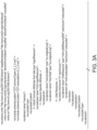
- the document shown in FIG. 16 depicts an example resource definition for the LWM2M Server Info object.
- various resource information is provided to identify the resource by name and type and to provide meta-data about the resource such as version number, short name, resource label, and where in the resource tree the resource can exist.
- the sections Resource Attributes, Resource Specific Attributes, and Child Resources comprise the contents that go into a oneM2M XSD file.
- the Activation Criteria section provides instructions to the service layer on how to activate the definition document to enable the use of the resource.
- the resource definition document is used as part of interworking support, it could also be used in normal service layer operations to register new resource types or resources based on existing types.
- a service layer that is deployed with version 1.0 of a certain resource type can be upgraded to support version 1.1 of the same resource in the future using the ideas presented above.
- the resource can also be a service layer only resource that does not need a data model mapping document. This is why the resource definition document and the data model mapping document are registered separately and only the resource definition needs to be activated.
- the service layer can also support custom resources created by a service layer owner, as in the case of a localized service layer deployment in home automation.
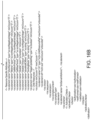
- FIG. 18 shows an example data model mapping document that the IPE registers to the service layer. Since the IPE supports periodic retargeting, the lifetime attribute's retargeting level is set to 0 (one-time retarget). The IPE supports this capability and will dynamically update this resource attribute so the service layer will always have the latest value. For other attributes in FIG. 17 with a retargeting indicator of 2 (retarget on change), the IPE does not support this feature. Thus, those values are set to 1 (always retarget).
- oneM2M's ⁇ mgmtObj> resource provides the ability to create specialized resources for use in device management (e.g., LWM2M) through the objectAttribute attribute. This is a customizable attribute that could be used for mapping directly to data model resources of the underlying device management technology.
- the mgmtDefinition and objectIDs attributes define what type of specialization object the ⁇ mgmtObj> resource is customized for. Currently, these attributes are defined within the standardization process and therefore do not offer the flexibility to dynamically define new specializations.
- the current oneM2M ⁇ mgmtObj> resource may be updated to dynamically support new specialization resources.
- Table 5 shows the resource specific attributes for the ⁇ mgmtObj> resource as well as the proposed change to the objectIDs attribute in order to support dynamically defining new specialization resources.
- the change expands on the definition of the ⁇ mgmtObj> resource to modify the objectIDs attribute to provide either a URN or a URI for the XSD of the specialized ⁇ mgmtObj> resource that corresponds to a LWM2M Object definition.
- the objectIDs may be specified during the creation of the specialized ⁇ mgmtObj> resource.
- Table 5 ⁇ mgmtObj> Resource Specific Attributes Attributes of ⁇ mgmtObj > Multiplicity RW/ RO/ WO Description ⁇ mgmtObjAnnc > Attributes mgmtDefinition 1 WO Specifies the type of ⁇ mgmtObj > resource (e.g., software, firmware, memory). The list of the value of the attribute can be seen in annex D.
- RW Contains the list URNs or a URI of an XSD file that uniquely identifies the technology specific data model objects used for this ⁇ mgmtObj > resource as well as the managed function and version it represents.
- This attribute may be provided during the creation of the ⁇ mgmtObj> resource and may not be modifiable afterwards. If the ⁇ mgmtObj> resource is mapped to multiple technology specific data model objects, this attribute may list all URNs for each mapped technology specific data model object. This is mandatory for the ⁇ mgmtObj>, for which the data model is not specified by oneM2M but mapped from technology specific data model.
- RW Contains the list of local paths of the technology specific data model objects on the managed entity which is represented by the ⁇ mgmtObj> resource in the Hosting CSE.
- This attribute may be provided during the creation of the ⁇ mgmtObj > so that the Hosting CSE can correlate the created ⁇ mgmtObj> with the technology specific data model object on the managed entity for further management operations. It may not be modifiable after creation.
- the format of this attribute may be a local technology specific data model object path in the form as specified by technology specific protocol.
- FIG. 19 shows an updated procedure a oneM2M Hosting CSE executes to create a new, specialized ⁇ mgmtObj> resource using the objectIDs attribute.
- step 002 the Receiver:
- step 003 the Receiver checks if the specialized ⁇ mgmtObj> resource is found in the supportedResourceType attribute of the CSEBase. If the specialized ⁇ mgmtObj> resource is found in the supportedResourceType attribute, go to Step 8; otherwise, go to Step 4.
- step 004 the Receiver extracts the contents of the objectIDs attribute and retrieves an XSD from the XSD Repository.
- step 005 the XSD Repository returns the XSD for the specialized ⁇ mgmtObj> resource.
- step 006 the Receiver checks that the received XSD is well formed and if it is, saves the XSD to the Receiver's local XSD repository.
- step 007 the Receiver updates the supportedResourceType attribute with the name of the specialized ⁇ mgmtObj>.
- step 008 the Receiver completes processing the CREATE request. This may include:
- the resource with the specified name already exists at the Receiver. In such a case, the Receiver may respond with an error.
- the provided information in Content is not accepted by the Receiver (e.g., missing mandatory parameter). In such a case, the Receiver may respond with an error.
- step 1 an AE performs a retrieve of the defMinPeriod attribute of the LWM2M Server Info resource lwm2m1.
- step 6 the LWM2M Device returns a "2.05 Content” response code with the appropriate value: 86400.
- step 7 the IPE returns the same value to the CSE after it has converted the LWM2M response to a oneM2M response format.
- step 9 the CSE returns an appropriate response to the AE along with the value 86400.
- a oneM2M ⁇ flexContainer> resource provides the ability to specify the location of an XSD file to describe the contents of a new resource derived from the base ⁇ flexContainer> resource through the containerDefinition attribute.
- the oneM2M specification TS-0001 does not specify how the CSE processes such a request and has identified a list of the specializations that use the ⁇ flexContainer> resource.
- FIG. 21 provides an example of how the creation of a ⁇ flexContainer> resource could be integrated to provide the ability to register and activate new resource definitions based on the ⁇ flexContainer> resource. These new resources will still be classified as a ⁇ flexContainer> resource type. Thus, a resource definition is not needed.
- step 1 the AE creates a ⁇ flexContainer> resource and specifies a containerDefinition attribute with a URI of the location of the XSD file.
- step 3 if the ACP check was successful, the CSE validates the request to make sure all required information is present in the request. As part of this validation, the CSE checks that the containerDefinition attribute is present.
- step 4 if the validation request from step 3 and the authorization check from step 2 are successful, the CSE checks if an XSD file exists in its local repository that matches the ⁇ flexContainer> resource provided in the payload of the request.
- step 6 the CSE receives the XSD file.
- step 7 as part of the activation procedure, the CSE checks that the XSD file is well formed.
- step 8 the CSE saves the XSD file to its local repository for future use if the XSD file is well formed.
- step 9 the CSE also updates the supportedResourceType attribute at the CSE base resource.
- step 10 the CSE validates the requested resource against the XSD.
- step 11 if all the previous checks were successful, the CSE creates the ⁇ flexContainer> resource.
- step 12 the CSE sends an appropriate response depending on the status of the checks in this procedure.
- FIG. 22 shows an example of two vendors that have interworked their devices to the CSE, as discussed below.
- each vendor can offer their services to a common service layer platform and provide for differentiation of their product offerings.
- An AE can then discover and access those resources to obtain services from each of the vendors without the need to understand each vendor's data model.
- step 0 the interworking system is configured and operational with all CSE registrations (IPEs and AE) completed and successful. Vendors A and B have interworked their resources to the CSE using the resource definition and data model mapping registration procedures. The AE has discovered resources of both vendors and would like to access them.
- CSE registrations IPEs and AE
- step 1 the AE performs a request on a VendorA resource.
- step 3 the CSE sends the retargeted request to VendorA/IPE and receives a response.
- step 4 the CSE returns a response to AE with the data from VendorA's resource.
- steps 5-8 repeat steps 1 to 4 for VendorB's resource.
- FIG. 22 is very similar to the example presented in FIG. 6 , the main difference being that the latter involves interworking between different systems while the former could involve vendors in different fields or even in the same field. In each case, applications can seamlessly access these varying resources using native service layer procedures.
- the LWM2M architecture allows multiple LWM2M servers to manage the same LWM2M client or device.
- FIG. 23 shows such an example scenario with LWM2M Server1 being the traditional server and LWM2M Server2 being the interworked server, as discussed below.
- both LWM2M servers are actively managing the LWM2M Device.
- LWM2M Server2/IPE has configured a retargeting indicator of "Change on update" for the firmware version resource of the Firmware Update object. As a result, LWM2M Server2 has made an observe request to get notifications of FW update.
- step 0 the interworking system is configured and operational with all CSE registrations completed and successful.
- the LWM2M Device is being managed by a traditional LWM2M Server1 and an interworked LWM2M Server2.
- LWM2M Server2 which is integrated with the IPE, has an observation on the firmware version resource of the LWM2M Device and knows when a firmware update is performed and successful.
- the IPE supports keeping the firmware version attribute updated on the CSE and configures the associated data model mapping to one-time retarget.
- step 2 LWM2M Device sends a notification to LWM2M Server2 with the new firmware version.
- step 3 the IPE makes a determination to update the firmware version on the CSE based on the retargeting indicator.
- step 4 the IPE updates the firmware version attribute on the CSE with the new version number.
- FIGs. 9-14 and 19-23 may be performed by the respective entities depicted in those figures, which may represent logical entities in a communication network and may be implemented in the form of software (i.e., computer-executable instructions) stored in a memory of, and executing on a processor of, an apparatus of such network, which may comprise one of the general architectures illustrated in FIGs. 25C or 25D described more fully below. That is, the operations illustrated in FIGs. 9-14 and 19-23 may be implemented in the form of software (i.e., computer-executable instructions) stored in a memory of a network apparatus, such as for example an apparatus having one of the architectures illustrated in FIGs.
- any transmitting and receiving steps illustrated in FIGs. 9-14 and 19-23 may be performed by communication circuitry (e.g., circuitry 34 or 97 of FIGs. 25C and 25D , respectively) of the appartus under control of the processor of the apparatus and the computer-executable instructions (e.g., software) that it executes.
- communication circuitry e.g., circuitry 34 or 97 of FIGs. 25C and 25D , respectively
- the computer-executable instructions e.g., software
- FIG. 25A is a diagram of an example machine-to machine (M2M), Internet of Things (IoT), or Web of Things (WoT) communication system 10 in which one or more disclosed embodiments may be implemented.
- M2M technologies provide building blocks for the IoT/WoT, and any M2M device, M2M gateway, M2M server, or M2M service platform may be a component or apparatus of the IoT/WoT as well as an IoT/WoT Service Layer, etc.
- Any of the entities illustrated in any of FIGS. 1 , 4-15 and 19-23 may comprise a network apparatus of a communication system, such as the ones illustrated in FIGS. 25A-25D .
- the service layer may be a functional layer within a network service architecture.
- Service layers are typically situated above the application protocol layer such as HTTP, CoAP or MQTT and provide value added services to client applications.
- the service layer also provides an interface to core networks at a lower resource layer, such as for example, a control layer and transport/access layer.
- the service layer supports multiple categories of (service) capabilities or functionalities including a service definition, service runtime enablement, policy management, access control, and service clustering.
- service supports multiple categories of (service) capabilities or functionalities including a service definition, service runtime enablement, policy management, access control, and service clustering.
- M2M industry standards bodies, e.g., oneM2M, have been developing M2M service layers to address the challenges associated with the integration of M2M types of devices and applications into deployments such as the Internet/Web, cellular, enterprise, and home networks.
- a M2M service layer may provide applications and/or various devices with access to a collection of or a set of the above-mentioned capabilities or functionalities, supported by the service layer, which may be referred to as a CSE or SCL.
- CSE capabilities or functionalities
- a few examples include but are not limited to security, charging, data management, device management, discovery, provisioning, and connectivity management which may be commonly used by various applications.
- These capabilities or functionalities are made available to such various applications via APIs which make use of message formats, resource structures and resource representations defined by the M2M service layer.
- the CSE or SCL is a functional entity that may be implemented by hardware and/or software and that provides (service) capabilities or functionalities exposed to various applications and/or devices (i.e., functional interfaces between such functional entities) in order for them to use such capabilities or functionalities.
- the M2M/ IoT/WoT communication system 10 includes a communication network 12.
- the communication network 12 may be a fixed network (e.g., Ethernet, Fiber, ISDN, PLC, or the like) or a wireless network (e.g., WLAN, cellular, or the like) or a network of heterogeneous networks.
- the communication network 12 may be comprised of multiple access networks that provide content such as voice, data, video, messaging, broadcast, or the like to multiple users.
- the communication network 12 may employ one or more channel access methods, such as code division multiple access (CDMA), time division multiple access (TDMA), frequency division multiple access (FDMA), orthogonal FDMA (OFDMA), single-carrier FDMA (SC-FDMA), and the like.
- CDMA code division multiple access
- TDMA time division multiple access
- FDMA frequency division multiple access
- OFDMA orthogonal FDMA
- SC-FDMA single-carrier FDMA
- the communication network 12 may comprise other networks such as a core network, the Internet, a sensor network, an industrial control network, a personal area network, a fused personal network, a satellite network, a home network, or an enterprise network for example.
- the M2M/ IoT/WoT communication system 10 may include the Infrastructure Domain and the Field Domain.
- the Infrastructure Domain refers to the network side of the end-to-end M2M deployment
- the Field Domain refers to the area networks, usually behind an M2M gateway.
- the Field Domain and Infrastructure Domain may both comprise a variety of different network apparatuses (e.g., servers, gateways, device, and the like) of the network.
- the Field Domain may include M2M gateways 14 and devices 18. It will be appreciated that any number of M2M gateway devices 14 and M2M devices 18 may be included in the M2M/ IoT/WoT communication system 10 as desired.
- Each of the M2M gateway devices 14 and M2M devices 18 are configured to transmit and receive signals, using communications circuitry, via the communication network 12 or direct radio link.
- a M2M gateway 14 allows wireless M2M devices (e.g., cellular and non-cellular) as well as fixed network M2M devices (e.g., PLC) to communicate either through operator networks, such as the communication network 12 or direct radio link.
- the M2M devices 18 may collect data and send the data, via the communication network 12 or direct radio link, to an M2M application 20 or other M2M devices 18.
- the M2M devices 18 may also receive data from the M2M application 20 or an M2M device 18. Further, data and signals may be sent to and received from the M2M application 20 via an M2M Service Layer 22, as described below.
- M2M devices 18 and gateways 14 may communicate via various networks including, cellular, WLAN, WPAN (e.g., Zigbee, 6LoWPAN, Bluetooth), direct radio link, and wireline for example.
- Exemplary M2M devices include, but are not limited to, tablets, smart phones, medical devices, temperature and weather monitors, connected cars, smart meters, game consoles, personal digital assistants, health and fitness monitors, lights, thermostats, appliances, garage doors and other actuator-based devices, security devices, and smart outlets.
- the illustrated M2M Service Layer 22 in the field domain provides services for the M2M application 20, M2M gateways 14, and M2M devices 18 and the communication network 12. It will be understood that the M2M Service Layer 22 may communicate with any number of M2M applications, M2M gateways 14, M2M devices 18, and communication networks 12 as desired.
- the M2M Service Layer 22 may be implemented by one or more network apparatuses of the network, which may comprise servers, computers, devices, or the like.
- the M2M Service Layer 22 provides service capabilities that apply to M2M devices 18, M2M gateways 14, and M2M applications 20.
- the functions of the M2M Service Layer 22 may be implemented in a variety of ways, for example as a web server, in the cellular core network, in the cloud, etc.
- M2M Service Layer 22 Similar to the illustrated M2M Service Layer 22, there is the M2M Service Layer 22' in the Infrastructure Domain. M2M Service Layer 22' provides services for the M2M application 20' and the underlying communication network 12 in the infrastructure domain. M2M Service Layer 22' also provides services for the M2M gateways 14 and M2M devices 18 in the field domain. It will be understood that the M2M Service Layer 22' may communicate with any number of M2M applications, M2M gateways and M2M devices. The M2M Service Layer 22' may interact with a Service Layer by a different service provider. The M2M Service Layer 22' may be implemented by one or more network apparatuses of the network, which may comprise servers, computers, devices, virtual machines (e.g., cloud computing/storage farms, etc.) or the like.
- network apparatuses of the network which may comprise servers, computers, devices, virtual machines (e.g., cloud computing/storage farms, etc.) or the like.
- the M2M applications 20 and 20' may include applications in various industries such as, without limitation, transportation, health and wellness, connected home, energy management, asset tracking, and security and surveillance.
- the M2M Service Layer running across the devices, gateways, servers and other network apparatuses of the system, supports functions such as, for example, data collection, device management, security, billing, location tracking/geofencing, device/service discovery, and legacy systems integration, and provides these functions as services to the M2M applications 20 and 20'.
- a Service Layer such as the Service Layers 22 and 22' illustrated in FIG. 25B , defines a software middleware layer that supports value-added service capabilities through a set of Application Programming Interfaces (APIs) and underlying networking interfaces.
- APIs Application Programming Interfaces
- Both the ETSI M2M and oneM2M architectures define a Service Layer.
- ETSI M2M's Service Layer is referred to as the Service Capability Layer (SCL).
- SCL Service Capability Layer
- the SCL may be implemented in a variety of different nodes of the ETSI M2M architecture.
- an instance of the Service Layer may be implemented within an M2M device (where it is referred to as a device SCL (DSCL)), a gateway (where it is referred to as a gateway SCL (GSCL)) and/or a network node (where it is referred to as a network SCL (NSCL)).
- the oneM2M Service Layer supports a set of Common Service Functions (CSFs) (i.e., service capabilities).
- CSFs Common Service Functions
- An instantiation of a set of one or more particular types of CSFs is referred to as a Common Services Entity (CSE) which may be hosted on different types of network nodes (e.g., infrastructure node, middle node, application-specific node).
- CSE Common Services Entity
- the Third Generation Partnership Project (3GPP) has also defined an architecture for machine-type communications (MTC).
- MTC machine-type communications
- SCS Service Capability Server
- an instance of the Service Layer may be implemented as a logical entity (e.g., software, computer-executable instructions, and the like) executing either on one or more standalone nodes in the network, including servers, computers, and other computing devices or nodes, or as part of one or more existing nodes.
- an instance of a Service Layer or component thereof may be implemented in the form of software running on a network apparatus (e.g., server, computer, gateway, device or the like) having the general architecture illustrated in FIG.
- SOA Service Oriented Architecture
- ROA Resource-Oriented Architecture
- FIG. 25C is a block diagram of an example hardware/software architecture of an apparatus of a network, such as one of the entities illustrated in FIGS. 1 , 4-15 and 19-23 which may operate as an M2M server, gateway, device, or other network apparatus in an M2M network such as that illustrated in FIGS. 25A and 25B .
- the network apparatus 30 may include a processor 32, non-removable memory 44, removable memory 46, a speaker/microphone 38, a keypad 40, a display, touchpad, and/or indicators 42, a power source 48, a global positioning system (GPS) chipset 50, and other peripherals 52.
- GPS global positioning system
- the network apparatus 30 may also include communication circuitry, such as a transceiver 34 and a transmit/receive element 36. It will be appreciated that the network apparatus 30 may include any sub-combination of the foregoing elements while remaining consistent with an embodiment.
- This network apparatus may be an apparatus that implements the message template management capabilities and methods described herein, such as the methods illustrated and described in relation to FIGS. 9-14 and 19-23 .
- the processor 32 may be a general purpose processor, a special purpose processor, a conventional processor, a digital signal processor (DSP), a plurality of microprocessors, one or more microprocessors in association with a DSP core, a controller, a microcontroller, Application Specific Integrated Circuits (ASICs), Field Programmable Gate Array (FPGAs) circuits, any other type of integrated circuit (IC), a state machine, and the like.
- the processor 32 may execute computer-executable instructions stored in the memory (e.g., memory 44 and/or memory 46) of the network apparatus in order to perform the various required functions of the network apparatus.
- the processor 32 may perform signal coding, data processing, power control, input/output processing, and/or any other functionality that enables the network apparatus 30 to operate in a wireless or wired environment.
- the processor 32 may run application-layer programs (e.g., browsers) and/or radio access-layer (RAN) programs and/or other communications programs.
- the processor 32 may also perform security operations such as authentication, security key agreement, and/or cryptographic operations, such as at the access-layer and/or application layer for example.
- the processor 32 is coupled to its communication circuitry (e.g., transceiver 34 and transmit/receive element 36).
- the processor 32 may control the communication circuitry in order to cause the network apparatus 30 to communicate with other network apparatuses via the network to which it is connected.
- the processor 32 may control the communication circuitry in order to perform the transmitting and receiving steps described herein (e.g., in FIGS. 9-14 and 24-26) and in the claims. While FIG. 25C depicts the processor 32 and the transceiver 34 as separate components, it will be appreciated that the processor 32 and the transceiver 34 may be integrated together in an electronic package or chip.
- the network apparatus 30 may include any number of transmit/receive elements 36. More specifically, the network apparatus 30 may employ MIMO technology. Thus, in an embodiment, the network apparatus 30 may include two or more transmit/receive elements 36 (e.g., multiple antennas) for transmitting and receiving wireless signals.
- the transceiver 34 may be configured to modulate the signals that are to be transmitted by the transmit/receive element 36 and to demodulate the signals that are received by the transmit/receive element 36.
- the network apparatus 30 may have multimode capabilities.
- the transceiver 34 may include multiple transceivers for enabling the network apparatus 30 to communicate via multiple RATs, such as UTRA and IEEE 802.11, for example.
- the processor 32 may access information from, and store data in, any type of suitable memory, such as the non-removable memory 44 and/or the removable memory 46.
- the processor 32 may store session context in its memory, as described above.
- the non-removable memory 44 may include random-access memory (RAM), read-only memory (ROM), a hard disk, or any other type of memory storage device.
- the removable memory 46 may include a subscriber identity module (SIM) card, a memory stick, a secure digital (SD) memory card, and the like.
- SIM subscriber identity module
- SD secure digital
- the processor 32 may access information from, and store data in, memory that is not physically located on the network apparatus 30, such as on a server or a home computer.
Landscapes
- Engineering & Computer Science (AREA)
- Signal Processing (AREA)
- Computer Networks & Wireless Communication (AREA)
- Software Systems (AREA)
- Theoretical Computer Science (AREA)
- Physics & Mathematics (AREA)
- General Engineering & Computer Science (AREA)
- General Physics & Mathematics (AREA)
- Computer Security & Cryptography (AREA)
- Information Retrieval, Db Structures And Fs Structures Therefor (AREA)
- Mobile Radio Communication Systems (AREA)
- Computer And Data Communications (AREA)
- Communication Control (AREA)
- Data Exchanges In Wide-Area Networks (AREA)
Claims (2)
- Appareil comprenant un processeur (91), une mémoire (82) et des circuits de communication (97), l'appareil étant connecté à un réseau par l'intermédiaire de ses circuits de communication, l'appareil comprenant en outre des instructions exécutables par ordinateur stockées dans la mémoire de l'appareil qui, à leur exécution par le processeur de l'appareil, amènent l'appareil à réaliser des opérations comprenant :la réception, au niveau d'une couche de service (22), d'une demande d'enregistrement d'informations, les informations définissant un nouveau type de ressource personnalisée comprenant un ou plusieurs attributs de ressource personnalisée, dans lequel la demande comprend une définition de ressource pour définir le nouveau type de ressource personnalisée ;l'intégration des informations dans des opérations de la couche de service ; etl'exposition des informations en vue de leur découverte par d'autres appareils de réseau communiquant sur le réseau ;dans lequel les informations comprennent une définition de schéma XML ou JSON du nouveau type de ressource situé au niveau d'un identifiant de ressource uniforme, URI ;caractérisé en ce que l'appareil est amené à réaliser en outre des opérations comprenant :la réception d'une demande de création d'un mappage de modèle de données pour les un ou plusieurs attributs de ressource personnalisée, le mappage de modèle de données fournissant un ou plusieurs URI de ressources d'interfonctionnement et des indicateurs de reciblage pour indiquer quand il convient de recibler une demande de récupération ciblant les ressources d'interfonctionnement, les indicateurs de reciblage comprenant un reciblage unique, un reciblage permanent, un reciblage lors d'un changement et un reciblage périodique, et les indicateurs de reciblage étant indépendants pour des instances de ressources du nouveau type de ressource personnalisée ;la création du mappage du modèle de données au niveau de la couche de service ;la réception, au niveau de la couche de service (22), d'une demande de récupération ciblant une des ressources d'interfonctionnement ; etla détermination qu'il convient ou non de recibler la demande de récupération en fonction des indicateurs de reciblage.
- Appareil selon la revendication 1, dans lequel la réception des informations au niveau de la couche de service comprend la réception des informations au niveau d'une ressource virtuelle ou physique au sein de la couche de service.
Applications Claiming Priority (2)
| Application Number | Priority Date | Filing Date | Title |
|---|---|---|---|
| US201662405534P | 2016-10-07 | 2016-10-07 | |
| PCT/US2017/055552 WO2018067939A1 (fr) | 2016-10-07 | 2017-10-06 | Gestion de ressources de couche de service pour interfonctionnement et extensibilité génériques |
Publications (2)
| Publication Number | Publication Date |
|---|---|
| EP3523724A1 EP3523724A1 (fr) | 2019-08-14 |
| EP3523724B1 true EP3523724B1 (fr) | 2023-12-06 |
Family
ID=60183119
Family Applications (1)
| Application Number | Title | Priority Date | Filing Date |
|---|---|---|---|
| EP17790903.3A Active EP3523724B1 (fr) | 2016-10-07 | 2017-10-06 | Gestion de ressources de couche de service pour interfonctionnement et extensibilité génériques |
Country Status (6)
| Country | Link |
|---|---|
| US (4) | US11240093B2 (fr) |
| EP (1) | EP3523724B1 (fr) |
| JP (1) | JP7090603B2 (fr) |
| KR (2) | KR102224379B1 (fr) |
| CN (2) | CN109997114B (fr) |
| WO (1) | WO2018067939A1 (fr) |
Families Citing this family (27)
| Publication number | Priority date | Publication date | Assignee | Title |
|---|---|---|---|---|
| EP3523724B1 (fr) * | 2016-10-07 | 2023-12-06 | Convida Wireless, LLC | Gestion de ressources de couche de service pour interfonctionnement et extensibilité génériques |
| US10547519B2 (en) * | 2016-11-02 | 2020-01-28 | Servicenow, Inc. | System and method of associating metadata with computing resources across multiple providers |
| US10970138B2 (en) | 2017-05-09 | 2021-04-06 | Microsoft Technology Licensing, Llc | Modular applications using a common provisioning service |
| US11483418B2 (en) * | 2017-12-06 | 2022-10-25 | Intel Corporation | Plugin management for internet of things (IoT) network optimization |
| WO2019136120A1 (fr) * | 2018-01-03 | 2019-07-11 | Convida Wireless, Llc | Découverte inter-domaines entre des systèmes de couche de service et des systèmes de l'internet des objets |
| CN110858846A (zh) * | 2018-08-22 | 2020-03-03 | 京东方科技集团股份有限公司 | 资源配置方法、装置和存储介质 |
| US11121932B2 (en) * | 2019-04-10 | 2021-09-14 | Cisco Technology, Inc. | Method and apparatus for model mapping and dynamically enabling external model on the network device |
| WO2020241661A1 (fr) | 2019-05-30 | 2020-12-03 | 京セラ株式会社 | Dispositif de communication, procédé de commande de dispositif de communication, procédé de communication, serveur, et système de communication |
| JP2020195122A (ja) * | 2019-05-30 | 2020-12-03 | 京セラ株式会社 | 通信機器及びその制御方法 |
| WO2021126022A1 (fr) * | 2019-12-17 | 2021-06-24 | Telefonaktiebolaget Lm Ericsson (Publ) | Dispositif sans fil, nœud de réseau et procédés exécutés par celui-ci permettant de gérer des bandes de radiofréquences |
| WO2021146960A1 (fr) * | 2020-01-21 | 2021-07-29 | Oppo广东移动通信有限公司 | Procédé de découverte de point d'extrémité de message et appareil associé |
| CN116325700B (zh) * | 2020-07-22 | 2025-07-25 | 瑞典爱立信有限公司 | 针对计算设备提供网络接入信息 |
| CN111885058B (zh) * | 2020-07-23 | 2022-05-13 | 伊拉克巴士拉大学 | 物联网云中端到端智能设备通信的轻量级消息传递方法 |
| CN112558968B (zh) * | 2020-12-22 | 2023-10-17 | 北京飞讯数码科技有限公司 | 一种资源树视图的生成方法、装置、设备及存储介质 |
| KR20220156429A (ko) * | 2021-05-18 | 2022-11-25 | 현대자동차주식회사 | M2m 시스템에서 디지털 권한 관리를 지원하기 위한 방법 및 장치 |
| CN113259443B (zh) * | 2021-05-20 | 2023-09-29 | 远景智能国际私人投资有限公司 | 资源数据的更新系统、方法、装置、设备及可读存储介质 |
| US11743736B2 (en) * | 2021-06-07 | 2023-08-29 | Cypress Semiconductor Corporation | Sharing transmission mediums in WiFi-Bluetooth combination systems |
| US11799737B1 (en) | 2021-06-30 | 2023-10-24 | Juniper Networks, Inc. | Topology-based graphical user interface for network management systems |
| CN113626189B (zh) * | 2021-08-03 | 2024-02-06 | 优刻得科技股份有限公司 | 资源管理模型的构建方法、设备和介质 |
| US11425221B1 (en) * | 2021-09-03 | 2022-08-23 | Juniper Networks, Inc. | Runtime extensible application programming interface server |
| US12147472B2 (en) | 2021-10-19 | 2024-11-19 | Korea Electronics Technology Institute | Data interworking method between ONEM2M system and NGSI-LD system |
| KR102400201B1 (ko) * | 2021-11-02 | 2022-05-20 | 한국전자기술연구원 | 시맨틱 온톨로지를 활용한 oneM2M to NGSI-LD 표준 플랫폼 간 연동 방법 |
| US11949802B1 (en) | 2022-11-29 | 2024-04-02 | Pusan National University Industry-University Cooperation Foundation | Blockchain-based platform system for interworking with one machine-to-machine(oneM2M) and lightweight machine-to-machine (LWM2M), and method of implementing blockchain-based platform |
| KR102560613B1 (ko) * | 2022-11-29 | 2023-07-27 | 부산대학교 산학협력단 | oneM2M과 LWM2M와의 연동을 위한 블록체인 기반 플랫폼 시스템 및 블록체인 기반 플랫폼 구현 방법 |
| WO2024143597A1 (fr) * | 2022-12-28 | 2024-07-04 | 한국전자기술연구원 | Procédé de traitement d'abonnement et de notification pour un interfonctionnement de données entre des plateformes |
| WO2025011730A1 (fr) * | 2023-07-07 | 2025-01-16 | Telefonaktiebolaget Lm Ericsson (Publ) | Intégration de plateformes de dispositifs et de plateforme d'orchestration de conteneurs |
| US12455891B2 (en) * | 2023-11-09 | 2025-10-28 | Hewlett Packard Enterprise Development Lp | Multi-consumer versioning system for retrieving lists of changed objects |
Citations (1)
| Publication number | Priority date | Publication date | Assignee | Title |
|---|---|---|---|---|
| WO2007099520A2 (fr) * | 2006-03-01 | 2007-09-07 | France Telecom | Architecture de calcul de grille et procédé associé destiné à appeler/enregistrer des services de réseau en vue d'un abonnement |
Family Cites Families (69)
| Publication number | Priority date | Publication date | Assignee | Title |
|---|---|---|---|---|
| US6714987B1 (en) * | 1999-11-05 | 2004-03-30 | Nortel Networks Limited | Architecture for an IP centric distributed network |
| US7496652B2 (en) * | 2000-07-17 | 2009-02-24 | Teleservices Solutions, Inc. | Intelligent network providing network access services (INP-NAS) |
| US6910074B1 (en) * | 2000-07-24 | 2005-06-21 | Nortel Networks Limited | System and method for service session management in an IP centric distributed network |
| US7584274B2 (en) * | 2004-06-15 | 2009-09-01 | International Business Machines Corporation | Coordinating use of independent external resources within requesting grid environments |
| US20110016214A1 (en) * | 2009-07-15 | 2011-01-20 | Cluster Resources, Inc. | System and method of brokering cloud computing resources |
| US8935429B2 (en) * | 2006-12-19 | 2015-01-13 | Vmware, Inc. | Automatically determining which remote applications a user or group is entitled to access based on entitlement specifications and providing remote application access to the remote applications |
| US20080021918A1 (en) * | 2005-12-23 | 2008-01-24 | Rao Viswanatha H | Enterprise service management unifier system |
| US20070174429A1 (en) * | 2006-01-24 | 2007-07-26 | Citrix Systems, Inc. | Methods and servers for establishing a connection between a client system and a virtual machine hosting a requested computing environment |
| US8468338B2 (en) * | 2006-07-06 | 2013-06-18 | Apple, Inc. | Wireless access point security for multi-hop networks |
| US8234702B2 (en) * | 2006-08-29 | 2012-07-31 | Oracle International Corporation | Cross network layer correlation-based firewalls |
| US8804534B2 (en) * | 2007-05-19 | 2014-08-12 | Cisco Technology, Inc. | Interworking between MPLS/IP and Ethernet OAM mechanisms |
| US7961711B2 (en) * | 2007-08-06 | 2011-06-14 | Microsoft Corporation | Fitness based routing |
| CN101309227B (zh) * | 2008-07-17 | 2011-11-30 | 中兴通讯股份有限公司 | 一种家庭网关策略控制的装置、系统及其实现方法 |
| US8250215B2 (en) * | 2008-08-12 | 2012-08-21 | Sap Ag | Method and system for intelligently leveraging cloud computing resources |
| US8244559B2 (en) * | 2009-06-26 | 2012-08-14 | Microsoft Corporation | Cloud computing resource broker |
| US9329951B2 (en) * | 2009-07-31 | 2016-05-03 | Paypal, Inc. | System and method to uniformly manage operational life cycles and service levels |
| US9246953B2 (en) * | 2009-11-19 | 2016-01-26 | Oracle International Corporation | Protocol level communications for protocol level composition with session sharing |
| US9519728B2 (en) * | 2009-12-04 | 2016-12-13 | Time Warner Cable Enterprises Llc | Apparatus and methods for monitoring and optimizing delivery of content in a network |
| GB2477092A (en) * | 2010-01-20 | 2011-07-27 | Nec Corp | Selecting virtual machine host servers based on client device location |
| CN102907068A (zh) * | 2010-03-09 | 2013-01-30 | 交互数字专利控股公司 | 支持机器对机器通信的方法和设备 |
| US9215079B2 (en) * | 2010-04-18 | 2015-12-15 | Tropo, Inc. | Servlet API and method for XMPP protocol |
| CN102238573A (zh) * | 2010-04-30 | 2011-11-09 | 中兴通讯股份有限公司 | 一种m2m业务的架构及实现m2m业务的方法 |
| WO2012013401A1 (fr) * | 2010-07-27 | 2012-02-02 | Telefonaktiebolaget L M Ericsson (Publ) | Contrôle d'abonnement de communication du type machine |
| EP2609502A4 (fr) * | 2010-08-24 | 2017-03-29 | Jay Moorthi | Procédé et appareil permettant de compenser une demande d'informatique en nuage |
| WO2012031112A2 (fr) * | 2010-09-03 | 2012-03-08 | Time Warner Cable, Inc. | Procédés et systèmes de gestion de centre de données virtuel avec un contrôle d'accès à base de rôles intégrés |
| CN102136933B (zh) * | 2010-09-30 | 2013-08-28 | 华为技术有限公司 | 设备管理方法、中间件及机器通信平台、设备和系统 |
| US8756323B2 (en) * | 2010-11-26 | 2014-06-17 | International Business Machines Corporation | Semantic- and preference-based planning of cloud service templates |
| US8527633B2 (en) * | 2011-01-06 | 2013-09-03 | International Business Machines Corporation | Techniques for addressing geographical location issues in computing environments |
| US9426222B2 (en) * | 2011-02-11 | 2016-08-23 | Interdigital Patent Holdings, Inc. | Systems, methods and apparatus for managing machine-to-machine (M2M) entities |
| TWI595764B (zh) * | 2011-04-11 | 2017-08-11 | 內數位專利控股公司 | 無線傳輸/接收單元及其執行的方法 |
| US9336060B2 (en) * | 2011-06-17 | 2016-05-10 | Microsoft Technology Licensing, Llc | Middleware services framework for on-premises and cloud deployment |
| US8793378B2 (en) * | 2011-09-01 | 2014-07-29 | International Business Machines Corporation | Identifying services and associated capabilities in a networked computing environment |
| US9781205B2 (en) * | 2011-09-12 | 2017-10-03 | Microsoft Technology Licensing, Llc | Coordination engine for cloud selection |
| TWI625048B (zh) * | 2011-10-24 | 2018-05-21 | 內數位專利控股公司 | 在複數服務層之間機器到機器(m2m)通信的方法、系統及裝置 |
| KR101807317B1 (ko) * | 2011-11-15 | 2017-12-08 | 주식회사 케이티 | M2m 통신 개체간 통지 기능을 구현하는 방법 및 장치 |
| CN103200209B (zh) * | 2012-01-06 | 2018-05-25 | 华为技术有限公司 | 成员资源的访问方法、群组服务器和成员设备 |
| EP3024256B1 (fr) * | 2012-02-03 | 2019-11-06 | Iot Holdings, Inc. | Procédé et appareil pour supporter des services à base de contexte et contenu m2m |
| US9508102B2 (en) * | 2012-07-25 | 2016-11-29 | Facebook, Inc. | Methods and systems for tracking of user interactions with content in social networks |
| US9106561B2 (en) * | 2012-12-06 | 2015-08-11 | A10 Networks, Inc. | Configuration of a virtual service network |
| KR20150092108A (ko) * | 2012-12-05 | 2015-08-12 | 엘지전자 주식회사 | 무선 통신 시스템에서 정보 변경 통지를 위한 방법 및 장치 |
| KR101467173B1 (ko) * | 2013-02-04 | 2014-12-01 | 주식회사 케이티 | M2m 네트워크의 리소스 관리 방법 및 리소스 관리 장치 |
| EP2957085B1 (fr) * | 2013-02-15 | 2020-09-16 | Convida Wireless, LLC | Propagation de ressources de couches de service entre domaines |
| EP2961122B1 (fr) | 2013-02-19 | 2021-08-11 | LG Electronics Inc. | Procédé pour modifier un paramètre de service m2m et appareil associé |
| KR101538714B1 (ko) * | 2013-02-26 | 2015-07-22 | 주식회사 케이티 | M2m 네트워크를 이용하는 복수의 디바이스간 상관관계 분석을 통한 네트워크 운영 방법 및 시스템 |
| US9716634B2 (en) * | 2013-03-15 | 2017-07-25 | International Business Machines Corporation | Fulfillment of cloud service orders |
| KR101999039B1 (ko) * | 2013-05-06 | 2019-07-10 | 콘비다 와이어리스, 엘엘씨 | 디바이스 트리거링 |
| CN105432103B (zh) * | 2013-05-22 | 2019-01-01 | 康维达无线有限责任公司 | 接入网络辅助引导自举 |
| US10057173B2 (en) * | 2013-05-28 | 2018-08-21 | Convida Wireless, Llc | Load balancing in the Internet of things |
| WO2015013485A2 (fr) * | 2013-07-24 | 2015-01-29 | Convida Wireless, Llc | Systèmes et procédés de décompte de domaine de service |
| US10200353B2 (en) * | 2013-07-25 | 2019-02-05 | Convida Wireless, Llc | End-to-end M2M service layer sessions |
| GB2518254B (en) * | 2013-09-13 | 2020-12-16 | Vodafone Ip Licensing Ltd | Communicating with a machine to machine device |
| KR101830887B1 (ko) * | 2013-09-20 | 2018-02-26 | 콘비다 와이어리스, 엘엘씨 | 근접성 서비스 및 사물 인터넷 서비스를 위한 조인트 등록 및 등록 해제 방법 |
| CN105580396B (zh) * | 2013-09-27 | 2019-04-16 | Lg电子株式会社 | 用于在m2m系统中传送通知消息的方法及其装置 |
| EP3061273B1 (fr) * | 2013-10-24 | 2020-06-17 | Convida Wireless, LLC | Système et procédé de gestion de couverture de service |
| US9401954B2 (en) * | 2013-11-06 | 2016-07-26 | International Business Machines Corporation | Scaling a trusted computing model in a globally distributed cloud environment |
| WO2015080515A1 (fr) * | 2013-11-29 | 2015-06-04 | 엘지전자 주식회사 | Procédé d'authentification basée sur la ressource, d'un abonnement à un service, dans une système de communications sans fil |
| KR101793204B1 (ko) * | 2014-03-18 | 2017-11-02 | 지티이 코포레이션 | M2m 네트워크에 있어서의 리소스 및 속성 관리 |
| KR20180079475A (ko) * | 2014-07-21 | 2018-07-10 | 콘비다 와이어리스, 엘엘씨 | Mqtt 프로토콜을 이용한 서비스 층 상호연동 |
| US9445248B2 (en) * | 2014-07-25 | 2016-09-13 | Qualcomm Incorporated | Radio-agnostic message translation service |
| US10931762B2 (en) | 2014-09-17 | 2021-02-23 | Convida Wireless, Llc | Systems and methods for enabling access to third party services via a service layer |
| US9459903B2 (en) * | 2014-09-24 | 2016-10-04 | Intel Corporation | Techniques for routing service chain flow packets between virtual machines |
| CN105611484B (zh) * | 2014-11-03 | 2020-07-10 | 中兴通讯股份有限公司 | 一种m2m节点的管理方法和装置 |
| KR101975845B1 (ko) * | 2014-12-30 | 2019-05-08 | 콘비다 와이어리스, 엘엘씨 | M2m 시스템들에 대한 시맨틱 주석 및 시맨틱 저장소 |
| WO2016153997A1 (fr) * | 2015-03-20 | 2016-09-29 | Convida Wireless, Llc | Procédés de prise en charge de routage de messages dans une couche de service |
| US20170064488A1 (en) * | 2015-08-26 | 2017-03-02 | Qualcomm Incorporated | Customized resource types for machine-to-machine communication |
| US10623145B2 (en) * | 2015-10-09 | 2020-04-14 | Telefonaktiebolaget Lm Ericsson (Publ) | Network node, wireless device and methods performed thereby for the network node to provide information to the wireless device |
| CN106888437B (zh) * | 2015-12-15 | 2020-07-07 | 华为技术有限公司 | 一种群组多播和群组创建的方法以及移动网络平台 |
| EP3523724B1 (fr) * | 2016-10-07 | 2023-12-06 | Convida Wireless, LLC | Gestion de ressources de couche de service pour interfonctionnement et extensibilité génériques |
| US10042685B1 (en) * | 2017-03-17 | 2018-08-07 | Accenture Global Solutions Limited | Extensible single point orchestration system for application program interfaces |
-
2017
- 2017-10-06 EP EP17790903.3A patent/EP3523724B1/fr active Active
- 2017-10-06 US US15/726,956 patent/US11240093B2/en active Active
- 2017-10-06 WO PCT/US2017/055552 patent/WO2018067939A1/fr not_active Ceased
- 2017-10-06 JP JP2019518452A patent/JP7090603B2/ja active Active
- 2017-10-06 KR KR1020197013108A patent/KR102224379B1/ko active Active
- 2017-10-06 CN CN201780071831.XA patent/CN109997114B/zh active Active
- 2017-10-06 KR KR1020217006283A patent/KR102389004B1/ko active Active
- 2017-10-06 CN CN202311218363.8A patent/CN117170876A/zh active Pending
-
2022
- 2022-01-04 US US17/568,162 patent/US11799711B2/en active Active
-
2023
- 2023-09-06 US US18/461,965 patent/US12177061B2/en active Active
-
2024
- 2024-11-22 US US18/957,397 patent/US20250202758A1/en active Pending
Patent Citations (1)
| Publication number | Priority date | Publication date | Assignee | Title |
|---|---|---|---|---|
| WO2007099520A2 (fr) * | 2006-03-01 | 2007-09-07 | France Telecom | Architecture de calcul de grille et procédé associé destiné à appeler/enregistrer des services de réseau en vue d'un abonnement |
Also Published As
| Publication number | Publication date |
|---|---|
| JP7090603B2 (ja) | 2022-06-24 |
| CN109997114B (zh) | 2023-09-29 |
| US11240093B2 (en) | 2022-02-01 |
| US20180102934A1 (en) | 2018-04-12 |
| WO2018067939A1 (fr) | 2018-04-12 |
| KR20210027527A (ko) | 2021-03-10 |
| EP3523724A1 (fr) | 2019-08-14 |
| JP2020506564A (ja) | 2020-02-27 |
| US20250202758A1 (en) | 2025-06-19 |
| KR102389004B1 (ko) | 2022-04-22 |
| US11799711B2 (en) | 2023-10-24 |
| KR102224379B1 (ko) | 2021-03-08 |
| US12177061B2 (en) | 2024-12-24 |
| US20240080235A1 (en) | 2024-03-07 |
| CN117170876A (zh) | 2023-12-05 |
| US20220131738A1 (en) | 2022-04-28 |
| KR20190065372A (ko) | 2019-06-11 |
| CN109997114A (zh) | 2019-07-09 |
Similar Documents
| Publication | Publication Date | Title |
|---|---|---|
| US12177061B2 (en) | Service layer resource management for generic interworking and extensibility | |
| EP3172859B1 (fr) | Interfonctionnement de protocole de machine à machine léger et de protocole de gestion de dispositif | |
| US10999380B2 (en) | Method and apparatus of interworking M2M and IoT devices and applications with different service layers | |
| KR102036420B1 (ko) | 머신-투-머신 시스템에서의 애플리케이션 관계 관리 | |
| US12126999B2 (en) | Context aware authorization for data and services in the IoT/M2M service layer | |
| US11936749B2 (en) | Cross-domain discovery between service layer systems and web of things systems |
Legal Events
| Date | Code | Title | Description |
|---|---|---|---|
| STAA | Information on the status of an ep patent application or granted ep patent |
Free format text: STATUS: UNKNOWN |
|
| STAA | Information on the status of an ep patent application or granted ep patent |
Free format text: STATUS: THE INTERNATIONAL PUBLICATION HAS BEEN MADE |
|
| PUAI | Public reference made under article 153(3) epc to a published international application that has entered the european phase |
Free format text: ORIGINAL CODE: 0009012 |
|
| STAA | Information on the status of an ep patent application or granted ep patent |
Free format text: STATUS: REQUEST FOR EXAMINATION WAS MADE |
|
| 17P | Request for examination filed |
Effective date: 20190507 |
|
| AK | Designated contracting states |
Kind code of ref document: A1 Designated state(s): AL AT BE BG CH CY CZ DE DK EE ES FI FR GB GR HR HU IE IS IT LI LT LU LV MC MK MT NL NO PL PT RO RS SE SI SK SM TR |
|
| AX | Request for extension of the european patent |
Extension state: BA ME |
|
| DAV | Request for validation of the european patent (deleted) | ||
| DAX | Request for extension of the european patent (deleted) | ||
| STAA | Information on the status of an ep patent application or granted ep patent |
Free format text: STATUS: EXAMINATION IS IN PROGRESS |
|
| 17Q | First examination report despatched |
Effective date: 20210616 |
|
| GRAP | Despatch of communication of intention to grant a patent |
Free format text: ORIGINAL CODE: EPIDOSNIGR1 |
|
| STAA | Information on the status of an ep patent application or granted ep patent |
Free format text: STATUS: GRANT OF PATENT IS INTENDED |
|
| P01 | Opt-out of the competence of the unified patent court (upc) registered |
Effective date: 20230517 |
|
| INTG | Intention to grant announced |
Effective date: 20230614 |
|
| GRAS | Grant fee paid |
Free format text: ORIGINAL CODE: EPIDOSNIGR3 |
|
| GRAA | (expected) grant |
Free format text: ORIGINAL CODE: 0009210 |
|
| STAA | Information on the status of an ep patent application or granted ep patent |
Free format text: STATUS: THE PATENT HAS BEEN GRANTED |
|
| AK | Designated contracting states |
Kind code of ref document: B1 Designated state(s): AL AT BE BG CH CY CZ DE DK EE ES FI FR GB GR HR HU IE IS IT LI LT LU LV MC MK MT NL NO PL PT RO RS SE SI SK SM TR |
|
| REG | Reference to a national code |
Ref country code: GB Ref legal event code: FG4D |
|
| REG | Reference to a national code |
Ref country code: CH Ref legal event code: EP |
|
| REG | Reference to a national code |
Ref country code: DE Ref legal event code: R096 Ref document number: 602017077261 Country of ref document: DE |
|
| REG | Reference to a national code |
Ref country code: IE Ref legal event code: FG4D |
|
| REG | Reference to a national code |
Ref country code: NL Ref legal event code: FP |
|
| REG | Reference to a national code |
Ref country code: LT Ref legal event code: MG9D |
|
| PG25 | Lapsed in a contracting state [announced via postgrant information from national office to epo] |
Ref country code: GR Free format text: LAPSE BECAUSE OF FAILURE TO SUBMIT A TRANSLATION OF THE DESCRIPTION OR TO PAY THE FEE WITHIN THE PRESCRIBED TIME-LIMIT Effective date: 20240307 |
|
| PG25 | Lapsed in a contracting state [announced via postgrant information from national office to epo] |
Ref country code: LT Free format text: LAPSE BECAUSE OF FAILURE TO SUBMIT A TRANSLATION OF THE DESCRIPTION OR TO PAY THE FEE WITHIN THE PRESCRIBED TIME-LIMIT Effective date: 20231206 |
|
| PG25 | Lapsed in a contracting state [announced via postgrant information from national office to epo] |
Ref country code: ES Free format text: LAPSE BECAUSE OF FAILURE TO SUBMIT A TRANSLATION OF THE DESCRIPTION OR TO PAY THE FEE WITHIN THE PRESCRIBED TIME-LIMIT Effective date: 20231206 |
|
| PG25 | Lapsed in a contracting state [announced via postgrant information from national office to epo] |
Ref country code: LT Free format text: LAPSE BECAUSE OF FAILURE TO SUBMIT A TRANSLATION OF THE DESCRIPTION OR TO PAY THE FEE WITHIN THE PRESCRIBED TIME-LIMIT Effective date: 20231206 Ref country code: GR Free format text: LAPSE BECAUSE OF FAILURE TO SUBMIT A TRANSLATION OF THE DESCRIPTION OR TO PAY THE FEE WITHIN THE PRESCRIBED TIME-LIMIT Effective date: 20240307 Ref country code: ES Free format text: LAPSE BECAUSE OF FAILURE TO SUBMIT A TRANSLATION OF THE DESCRIPTION OR TO PAY THE FEE WITHIN THE PRESCRIBED TIME-LIMIT Effective date: 20231206 Ref country code: BG Free format text: LAPSE BECAUSE OF FAILURE TO SUBMIT A TRANSLATION OF THE DESCRIPTION OR TO PAY THE FEE WITHIN THE PRESCRIBED TIME-LIMIT Effective date: 20240306 |
|
| REG | Reference to a national code |
Ref country code: AT Ref legal event code: MK05 Ref document number: 1639068 Country of ref document: AT Kind code of ref document: T Effective date: 20231206 |
|
| PG25 | Lapsed in a contracting state [announced via postgrant information from national office to epo] |
Ref country code: SE Free format text: LAPSE BECAUSE OF FAILURE TO SUBMIT A TRANSLATION OF THE DESCRIPTION OR TO PAY THE FEE WITHIN THE PRESCRIBED TIME-LIMIT Effective date: 20231206 Ref country code: RS Free format text: LAPSE BECAUSE OF FAILURE TO SUBMIT A TRANSLATION OF THE DESCRIPTION OR TO PAY THE FEE WITHIN THE PRESCRIBED TIME-LIMIT Effective date: 20231206 Ref country code: NO Free format text: LAPSE BECAUSE OF FAILURE TO SUBMIT A TRANSLATION OF THE DESCRIPTION OR TO PAY THE FEE WITHIN THE PRESCRIBED TIME-LIMIT Effective date: 20240306 Ref country code: LV Free format text: LAPSE BECAUSE OF FAILURE TO SUBMIT A TRANSLATION OF THE DESCRIPTION OR TO PAY THE FEE WITHIN THE PRESCRIBED TIME-LIMIT Effective date: 20231206 Ref country code: HR Free format text: LAPSE BECAUSE OF FAILURE TO SUBMIT A TRANSLATION OF THE DESCRIPTION OR TO PAY THE FEE WITHIN THE PRESCRIBED TIME-LIMIT Effective date: 20231206 |
|
| PG25 | Lapsed in a contracting state [announced via postgrant information from national office to epo] |
Ref country code: IS Free format text: LAPSE BECAUSE OF FAILURE TO SUBMIT A TRANSLATION OF THE DESCRIPTION OR TO PAY THE FEE WITHIN THE PRESCRIBED TIME-LIMIT Effective date: 20240406 |
|
| PG25 | Lapsed in a contracting state [announced via postgrant information from national office to epo] |
Ref country code: AT Free format text: LAPSE BECAUSE OF FAILURE TO SUBMIT A TRANSLATION OF THE DESCRIPTION OR TO PAY THE FEE WITHIN THE PRESCRIBED TIME-LIMIT Effective date: 20231206 Ref country code: CZ Free format text: LAPSE BECAUSE OF FAILURE TO SUBMIT A TRANSLATION OF THE DESCRIPTION OR TO PAY THE FEE WITHIN THE PRESCRIBED TIME-LIMIT Effective date: 20231206 |
|
| PG25 | Lapsed in a contracting state [announced via postgrant information from national office to epo] |
Ref country code: SK Free format text: LAPSE BECAUSE OF FAILURE TO SUBMIT A TRANSLATION OF THE DESCRIPTION OR TO PAY THE FEE WITHIN THE PRESCRIBED TIME-LIMIT Effective date: 20231206 |
|
| PG25 | Lapsed in a contracting state [announced via postgrant information from national office to epo] |
Ref country code: SM Free format text: LAPSE BECAUSE OF FAILURE TO SUBMIT A TRANSLATION OF THE DESCRIPTION OR TO PAY THE FEE WITHIN THE PRESCRIBED TIME-LIMIT Effective date: 20231206 Ref country code: SK Free format text: LAPSE BECAUSE OF FAILURE TO SUBMIT A TRANSLATION OF THE DESCRIPTION OR TO PAY THE FEE WITHIN THE PRESCRIBED TIME-LIMIT Effective date: 20231206 Ref country code: RO Free format text: LAPSE BECAUSE OF FAILURE TO SUBMIT A TRANSLATION OF THE DESCRIPTION OR TO PAY THE FEE WITHIN THE PRESCRIBED TIME-LIMIT Effective date: 20231206 Ref country code: IT Free format text: LAPSE BECAUSE OF FAILURE TO SUBMIT A TRANSLATION OF THE DESCRIPTION OR TO PAY THE FEE WITHIN THE PRESCRIBED TIME-LIMIT Effective date: 20231206 Ref country code: IS Free format text: LAPSE BECAUSE OF FAILURE TO SUBMIT A TRANSLATION OF THE DESCRIPTION OR TO PAY THE FEE WITHIN THE PRESCRIBED TIME-LIMIT Effective date: 20240406 Ref country code: EE Free format text: LAPSE BECAUSE OF FAILURE TO SUBMIT A TRANSLATION OF THE DESCRIPTION OR TO PAY THE FEE WITHIN THE PRESCRIBED TIME-LIMIT Effective date: 20231206 Ref country code: CZ Free format text: LAPSE BECAUSE OF FAILURE TO SUBMIT A TRANSLATION OF THE DESCRIPTION OR TO PAY THE FEE WITHIN THE PRESCRIBED TIME-LIMIT Effective date: 20231206 Ref country code: AT Free format text: LAPSE BECAUSE OF FAILURE TO SUBMIT A TRANSLATION OF THE DESCRIPTION OR TO PAY THE FEE WITHIN THE PRESCRIBED TIME-LIMIT Effective date: 20231206 |
|
| PG25 | Lapsed in a contracting state [announced via postgrant information from national office to epo] |
Ref country code: PL Free format text: LAPSE BECAUSE OF FAILURE TO SUBMIT A TRANSLATION OF THE DESCRIPTION OR TO PAY THE FEE WITHIN THE PRESCRIBED TIME-LIMIT Effective date: 20231206 Ref country code: PT Free format text: LAPSE BECAUSE OF FAILURE TO SUBMIT A TRANSLATION OF THE DESCRIPTION OR TO PAY THE FEE WITHIN THE PRESCRIBED TIME-LIMIT Effective date: 20240408 |
|
| PG25 | Lapsed in a contracting state [announced via postgrant information from national office to epo] |
Ref country code: PT Free format text: LAPSE BECAUSE OF FAILURE TO SUBMIT A TRANSLATION OF THE DESCRIPTION OR TO PAY THE FEE WITHIN THE PRESCRIBED TIME-LIMIT Effective date: 20240408 Ref country code: PL Free format text: LAPSE BECAUSE OF FAILURE TO SUBMIT A TRANSLATION OF THE DESCRIPTION OR TO PAY THE FEE WITHIN THE PRESCRIBED TIME-LIMIT Effective date: 20231206 |
|
| REG | Reference to a national code |
Ref country code: DE Ref legal event code: R097 Ref document number: 602017077261 Country of ref document: DE |
|
| PG25 | Lapsed in a contracting state [announced via postgrant information from national office to epo] |
Ref country code: DK Free format text: LAPSE BECAUSE OF FAILURE TO SUBMIT A TRANSLATION OF THE DESCRIPTION OR TO PAY THE FEE WITHIN THE PRESCRIBED TIME-LIMIT Effective date: 20231206 |
|
| PLBE | No opposition filed within time limit |
Free format text: ORIGINAL CODE: 0009261 |
|
| STAA | Information on the status of an ep patent application or granted ep patent |
Free format text: STATUS: NO OPPOSITION FILED WITHIN TIME LIMIT |
|
| PG25 | Lapsed in a contracting state [announced via postgrant information from national office to epo] |
Ref country code: SI Free format text: LAPSE BECAUSE OF FAILURE TO SUBMIT A TRANSLATION OF THE DESCRIPTION OR TO PAY THE FEE WITHIN THE PRESCRIBED TIME-LIMIT Effective date: 20231206 |
|
| PG25 | Lapsed in a contracting state [announced via postgrant information from national office to epo] |
Ref country code: SI Free format text: LAPSE BECAUSE OF FAILURE TO SUBMIT A TRANSLATION OF THE DESCRIPTION OR TO PAY THE FEE WITHIN THE PRESCRIBED TIME-LIMIT Effective date: 20231206 Ref country code: DK Free format text: LAPSE BECAUSE OF FAILURE TO SUBMIT A TRANSLATION OF THE DESCRIPTION OR TO PAY THE FEE WITHIN THE PRESCRIBED TIME-LIMIT Effective date: 20231206 |
|
| 26N | No opposition filed |
Effective date: 20240909 |
|
| REG | Reference to a national code |
Ref country code: CH Ref legal event code: PL |
|
| PG25 | Lapsed in a contracting state [announced via postgrant information from national office to epo] |
Ref country code: MC Free format text: LAPSE BECAUSE OF FAILURE TO SUBMIT A TRANSLATION OF THE DESCRIPTION OR TO PAY THE FEE WITHIN THE PRESCRIBED TIME-LIMIT Effective date: 20231206 |
|
| PG25 | Lapsed in a contracting state [announced via postgrant information from national office to epo] |
Ref country code: LU Free format text: LAPSE BECAUSE OF NON-PAYMENT OF DUE FEES Effective date: 20241006 Ref country code: BE Free format text: LAPSE BECAUSE OF NON-PAYMENT OF DUE FEES Effective date: 20241031 |
|
| PG25 | Lapsed in a contracting state [announced via postgrant information from national office to epo] |
Ref country code: CH Free format text: LAPSE BECAUSE OF NON-PAYMENT OF DUE FEES Effective date: 20241031 |
|
| REG | Reference to a national code |
Ref country code: BE Ref legal event code: MM Effective date: 20241031 |
|
| REG | Reference to a national code |
Ref country code: GB Ref legal event code: 732E Free format text: REGISTERED BETWEEN 20250731 AND 20250806 |
|
| REG | Reference to a national code |
Ref country code: DE Ref legal event code: R081 Ref document number: 602017077261 Country of ref document: DE Owner name: INTERDIGITAL PATENT HOLDINGS, INC., WILMINGTON, US Free format text: FORMER OWNER: CONVIDA WIRELESS, LLC, WILMINGTON, DE, US Ref country code: NL Ref legal event code: PD Owner name: INTERDIGITAL PATENT HOLDINGS, INC.; US Free format text: DETAILS ASSIGNMENT: CHANGE OF OWNER(S), ASSIGNMENT; FORMER OWNER NAME: CONVIDA WIRELESS, LLC Effective date: 20250909 |
|
| PG25 | Lapsed in a contracting state [announced via postgrant information from national office to epo] |
Ref country code: FI Free format text: LAPSE BECAUSE OF FAILURE TO SUBMIT A TRANSLATION OF THE DESCRIPTION OR TO PAY THE FEE WITHIN THE PRESCRIBED TIME-LIMIT Effective date: 20231207 |
|
| PG25 | Lapsed in a contracting state [announced via postgrant information from national office to epo] |
Ref country code: IE Free format text: LAPSE BECAUSE OF NON-PAYMENT OF DUE FEES Effective date: 20241006 |
|
| PGFP | Annual fee paid to national office [announced via postgrant information from national office to epo] |
Ref country code: NL Payment date: 20251024 Year of fee payment: 9 |
|
| PGFP | Annual fee paid to national office [announced via postgrant information from national office to epo] |
Ref country code: DE Payment date: 20251028 Year of fee payment: 9 |
|
| PGFP | Annual fee paid to national office [announced via postgrant information from national office to epo] |
Ref country code: GB Payment date: 20251023 Year of fee payment: 9 |
|
| PGFP | Annual fee paid to national office [announced via postgrant information from national office to epo] |
Ref country code: FR Payment date: 20251027 Year of fee payment: 9 |
|
| PG25 | Lapsed in a contracting state [announced via postgrant information from national office to epo] |
Ref country code: CY Free format text: LAPSE BECAUSE OF FAILURE TO SUBMIT A TRANSLATION OF THE DESCRIPTION OR TO PAY THE FEE WITHIN THE PRESCRIBED TIME-LIMIT; INVALID AB INITIO Effective date: 20171006 |
|
| PG25 | Lapsed in a contracting state [announced via postgrant information from national office to epo] |
Ref country code: HU Free format text: LAPSE BECAUSE OF FAILURE TO SUBMIT A TRANSLATION OF THE DESCRIPTION OR TO PAY THE FEE WITHIN THE PRESCRIBED TIME-LIMIT; INVALID AB INITIO Effective date: 20171006 |