EP3523874B1 - Entraînement à vitesse variable pour un système cvcar - Google Patents
Entraînement à vitesse variable pour un système cvcar Download PDFInfo
- Publication number
- EP3523874B1 EP3523874B1 EP17791780.4A EP17791780A EP3523874B1 EP 3523874 B1 EP3523874 B1 EP 3523874B1 EP 17791780 A EP17791780 A EP 17791780A EP 3523874 B1 EP3523874 B1 EP 3523874B1
- Authority
- EP
- European Patent Office
- Prior art keywords
- power
- variable speed
- silicon carbide
- speed drive
- compressor
- Prior art date
- Legal status (The legal status is an assumption and is not a legal conclusion. Google has not performed a legal analysis and makes no representation as to the accuracy of the status listed.)
- Active
Links
Images




Classifications
-
- H—ELECTRICITY
- H02—GENERATION; CONVERSION OR DISTRIBUTION OF ELECTRIC POWER
- H02M—APPARATUS FOR CONVERSION BETWEEN AC AND AC, BETWEEN AC AND DC, OR BETWEEN DC AND DC, AND FOR USE WITH MAINS OR SIMILAR POWER SUPPLY SYSTEMS; CONVERSION OF DC OR AC INPUT POWER INTO SURGE OUTPUT POWER; CONTROL OR REGULATION THEREOF
- H02M5/00—Conversion of AC power input into AC power output, e.g. for change of voltage, for change of frequency, for change of number of phases
- H02M5/40—Conversion of AC power input into AC power output, e.g. for change of voltage, for change of frequency, for change of number of phases with intermediate conversion into DC
- H02M5/42—Conversion of AC power input into AC power output, e.g. for change of voltage, for change of frequency, for change of number of phases with intermediate conversion into DC by static converters
- H02M5/44—Conversion of AC power input into AC power output, e.g. for change of voltage, for change of frequency, for change of number of phases with intermediate conversion into DC by static converters using discharge tubes or semiconductor devices to convert the intermediate DC into AC
- H02M5/453—Conversion of AC power input into AC power output, e.g. for change of voltage, for change of frequency, for change of number of phases with intermediate conversion into DC by static converters using discharge tubes or semiconductor devices to convert the intermediate DC into AC using devices of a triode or transistor type requiring continuous application of a control signal
- H02M5/458—Conversion of AC power input into AC power output, e.g. for change of voltage, for change of frequency, for change of number of phases with intermediate conversion into DC by static converters using discharge tubes or semiconductor devices to convert the intermediate DC into AC using devices of a triode or transistor type requiring continuous application of a control signal using semiconductor devices only
- H02M5/4585—Conversion of AC power input into AC power output, e.g. for change of voltage, for change of frequency, for change of number of phases with intermediate conversion into DC by static converters using discharge tubes or semiconductor devices to convert the intermediate DC into AC using devices of a triode or transistor type requiring continuous application of a control signal using semiconductor devices only having a rectifier with controlled elements
-
- F—MECHANICAL ENGINEERING; LIGHTING; HEATING; WEAPONS; BLASTING
- F25—REFRIGERATION OR COOLING; COMBINED HEATING AND REFRIGERATION SYSTEMS; HEAT PUMP SYSTEMS; MANUFACTURE OR STORAGE OF ICE; LIQUEFACTION SOLIDIFICATION OF GASES
- F25B—REFRIGERATION MACHINES, PLANTS OR SYSTEMS; COMBINED HEATING AND REFRIGERATION SYSTEMS; HEAT PUMP SYSTEMS
- F25B25/00—Machines, plants or systems, using a combination of modes of operation covered by two or more of the groups F25B1/00 - F25B23/00
- F25B25/005—Machines, plants or systems, using a combination of modes of operation covered by two or more of the groups F25B1/00 - F25B23/00 using primary and secondary systems
-
- F—MECHANICAL ENGINEERING; LIGHTING; HEATING; WEAPONS; BLASTING
- F25—REFRIGERATION OR COOLING; COMBINED HEATING AND REFRIGERATION SYSTEMS; HEAT PUMP SYSTEMS; MANUFACTURE OR STORAGE OF ICE; LIQUEFACTION SOLIDIFICATION OF GASES
- F25B—REFRIGERATION MACHINES, PLANTS OR SYSTEMS; COMBINED HEATING AND REFRIGERATION SYSTEMS; HEAT PUMP SYSTEMS
- F25B41/00—Fluid-circulation arrangements
- F25B41/30—Expansion means; Dispositions thereof
- F25B41/39—Dispositions with two or more expansion means arranged in series, i.e. multi-stage expansion, on a refrigerant line leading to the same evaporator
-
- F—MECHANICAL ENGINEERING; LIGHTING; HEATING; WEAPONS; BLASTING
- F25—REFRIGERATION OR COOLING; COMBINED HEATING AND REFRIGERATION SYSTEMS; HEAT PUMP SYSTEMS; MANUFACTURE OR STORAGE OF ICE; LIQUEFACTION SOLIDIFICATION OF GASES
- F25B—REFRIGERATION MACHINES, PLANTS OR SYSTEMS; COMBINED HEATING AND REFRIGERATION SYSTEMS; HEAT PUMP SYSTEMS
- F25B49/00—Arrangement or mounting of control or safety devices
- F25B49/02—Arrangement or mounting of control or safety devices for compression type machines, plants or systems
- F25B49/025—Motor control arrangements
-
- H—ELECTRICITY
- H02—GENERATION; CONVERSION OR DISTRIBUTION OF ELECTRIC POWER
- H02M—APPARATUS FOR CONVERSION BETWEEN AC AND AC, BETWEEN AC AND DC, OR BETWEEN DC AND DC, AND FOR USE WITH MAINS OR SIMILAR POWER SUPPLY SYSTEMS; CONVERSION OF DC OR AC INPUT POWER INTO SURGE OUTPUT POWER; CONTROL OR REGULATION THEREOF
- H02M1/00—Details of apparatus for conversion
- H02M1/0048—Circuits or arrangements for reducing losses
- H02M1/0054—Transistor switching losses
-
- H—ELECTRICITY
- H02—GENERATION; CONVERSION OR DISTRIBUTION OF ELECTRIC POWER
- H02M—APPARATUS FOR CONVERSION BETWEEN AC AND AC, BETWEEN AC AND DC, OR BETWEEN DC AND DC, AND FOR USE WITH MAINS OR SIMILAR POWER SUPPLY SYSTEMS; CONVERSION OF DC OR AC INPUT POWER INTO SURGE OUTPUT POWER; CONTROL OR REGULATION THEREOF
- H02M1/00—Details of apparatus for conversion
- H02M1/08—Circuits specially adapted for the generation of control voltages for semiconductor devices incorporated in static converters
-
- H—ELECTRICITY
- H02—GENERATION; CONVERSION OR DISTRIBUTION OF ELECTRIC POWER
- H02M—APPARATUS FOR CONVERSION BETWEEN AC AND AC, BETWEEN AC AND DC, OR BETWEEN DC AND DC, AND FOR USE WITH MAINS OR SIMILAR POWER SUPPLY SYSTEMS; CONVERSION OF DC OR AC INPUT POWER INTO SURGE OUTPUT POWER; CONTROL OR REGULATION THEREOF
- H02M7/00—Conversion of AC power input into DC power output; Conversion of DC power input into AC power output
- H02M7/003—Constructional details, e.g. physical layout, assembly, wiring or busbar connections
-
- H—ELECTRICITY
- H02—GENERATION; CONVERSION OR DISTRIBUTION OF ELECTRIC POWER
- H02P—CONTROL OR REGULATION OF ELECTRIC MOTORS, ELECTRIC GENERATORS OR DYNAMO-ELECTRIC CONVERTERS; CONTROLLING TRANSFORMERS, REACTORS OR CHOKE COILS
- H02P27/00—Arrangements or methods for the control of AC motors characterised by the kind of supply voltage
- H02P27/04—Arrangements or methods for the control of AC motors characterised by the kind of supply voltage using variable-frequency supply voltage, e.g. inverter or converter supply voltage
- H02P27/06—Arrangements or methods for the control of AC motors characterised by the kind of supply voltage using variable-frequency supply voltage, e.g. inverter or converter supply voltage using DC to AC converters or inverters
-
- H—ELECTRICITY
- H10—SEMICONDUCTOR DEVICES; ELECTRIC SOLID-STATE DEVICES NOT OTHERWISE PROVIDED FOR
- H10D—INORGANIC ELECTRIC SEMICONDUCTOR DEVICES
- H10D99/00—Subject matter not provided for in other groups of this subclass
-
- F—MECHANICAL ENGINEERING; LIGHTING; HEATING; WEAPONS; BLASTING
- F25—REFRIGERATION OR COOLING; COMBINED HEATING AND REFRIGERATION SYSTEMS; HEAT PUMP SYSTEMS; MANUFACTURE OR STORAGE OF ICE; LIQUEFACTION SOLIDIFICATION OF GASES
- F25B—REFRIGERATION MACHINES, PLANTS OR SYSTEMS; COMBINED HEATING AND REFRIGERATION SYSTEMS; HEAT PUMP SYSTEMS
- F25B2339/00—Details of evaporators; Details of condensers
- F25B2339/04—Details of condensers
- F25B2339/047—Water-cooled condensers
-
- F—MECHANICAL ENGINEERING; LIGHTING; HEATING; WEAPONS; BLASTING
- F25—REFRIGERATION OR COOLING; COMBINED HEATING AND REFRIGERATION SYSTEMS; HEAT PUMP SYSTEMS; MANUFACTURE OR STORAGE OF ICE; LIQUEFACTION SOLIDIFICATION OF GASES
- F25B—REFRIGERATION MACHINES, PLANTS OR SYSTEMS; COMBINED HEATING AND REFRIGERATION SYSTEMS; HEAT PUMP SYSTEMS
- F25B2400/00—Component parts or details not otherwise provided for in this subclass
- F25B2400/13—Economisers
-
- F—MECHANICAL ENGINEERING; LIGHTING; HEATING; WEAPONS; BLASTING
- F25—REFRIGERATION OR COOLING; COMBINED HEATING AND REFRIGERATION SYSTEMS; HEAT PUMP SYSTEMS; MANUFACTURE OR STORAGE OF ICE; LIQUEFACTION SOLIDIFICATION OF GASES
- F25B—REFRIGERATION MACHINES, PLANTS OR SYSTEMS; COMBINED HEATING AND REFRIGERATION SYSTEMS; HEAT PUMP SYSTEMS
- F25B2400/00—Component parts or details not otherwise provided for in this subclass
- F25B2400/23—Separators
-
- F—MECHANICAL ENGINEERING; LIGHTING; HEATING; WEAPONS; BLASTING
- F25—REFRIGERATION OR COOLING; COMBINED HEATING AND REFRIGERATION SYSTEMS; HEAT PUMP SYSTEMS; MANUFACTURE OR STORAGE OF ICE; LIQUEFACTION SOLIDIFICATION OF GASES
- F25B—REFRIGERATION MACHINES, PLANTS OR SYSTEMS; COMBINED HEATING AND REFRIGERATION SYSTEMS; HEAT PUMP SYSTEMS
- F25B2600/00—Control issues
- F25B2600/02—Compressor control
- F25B2600/021—Inverters therefor
-
- F—MECHANICAL ENGINEERING; LIGHTING; HEATING; WEAPONS; BLASTING
- F25—REFRIGERATION OR COOLING; COMBINED HEATING AND REFRIGERATION SYSTEMS; HEAT PUMP SYSTEMS; MANUFACTURE OR STORAGE OF ICE; LIQUEFACTION SOLIDIFICATION OF GASES
- F25B—REFRIGERATION MACHINES, PLANTS OR SYSTEMS; COMBINED HEATING AND REFRIGERATION SYSTEMS; HEAT PUMP SYSTEMS
- F25B2700/00—Sensing or detecting of parameters; Sensors therefor
- F25B2700/17—Speeds
- F25B2700/171—Speeds of the compressor
-
- F—MECHANICAL ENGINEERING; LIGHTING; HEATING; WEAPONS; BLASTING
- F25—REFRIGERATION OR COOLING; COMBINED HEATING AND REFRIGERATION SYSTEMS; HEAT PUMP SYSTEMS; MANUFACTURE OR STORAGE OF ICE; LIQUEFACTION SOLIDIFICATION OF GASES
- F25B—REFRIGERATION MACHINES, PLANTS OR SYSTEMS; COMBINED HEATING AND REFRIGERATION SYSTEMS; HEAT PUMP SYSTEMS
- F25B2700/00—Sensing or detecting of parameters; Sensors therefor
- F25B2700/19—Pressures
- F25B2700/193—Pressures of the compressor
- F25B2700/1931—Discharge pressures
-
- H—ELECTRICITY
- H02—GENERATION; CONVERSION OR DISTRIBUTION OF ELECTRIC POWER
- H02P—CONTROL OR REGULATION OF ELECTRIC MOTORS, ELECTRIC GENERATORS OR DYNAMO-ELECTRIC CONVERTERS; CONTROLLING TRANSFORMERS, REACTORS OR CHOKE COILS
- H02P27/00—Arrangements or methods for the control of AC motors characterised by the kind of supply voltage
- H02P27/04—Arrangements or methods for the control of AC motors characterised by the kind of supply voltage using variable-frequency supply voltage, e.g. inverter or converter supply voltage
-
- H—ELECTRICITY
- H10—SEMICONDUCTOR DEVICES; ELECTRIC SOLID-STATE DEVICES NOT OTHERWISE PROVIDED FOR
- H10D—INORGANIC ELECTRIC SEMICONDUCTOR DEVICES
- H10D30/00—Field-effect transistors [FET]
- H10D30/60—Insulated-gate field-effect transistors [IGFET]
- H10D30/64—Double-diffused metal-oxide semiconductor [DMOS] FETs
-
- H—ELECTRICITY
- H10—SEMICONDUCTOR DEVICES; ELECTRIC SOLID-STATE DEVICES NOT OTHERWISE PROVIDED FOR
- H10D—INORGANIC ELECTRIC SEMICONDUCTOR DEVICES
- H10D62/00—Semiconductor bodies, or regions thereof, of devices having potential barriers
- H10D62/80—Semiconductor bodies, or regions thereof, of devices having potential barriers characterised by the materials
- H10D62/83—Semiconductor bodies, or regions thereof, of devices having potential barriers characterised by the materials being Group IV materials, e.g. B-doped Si or undoped Ge
- H10D62/832—Semiconductor bodies, or regions thereof, of devices having potential barriers characterised by the materials being Group IV materials, e.g. B-doped Si or undoped Ge being Group IV materials comprising two or more elements, e.g. SiGe
- H10D62/8325—Silicon carbide
-
- Y—GENERAL TAGGING OF NEW TECHNOLOGICAL DEVELOPMENTS; GENERAL TAGGING OF CROSS-SECTIONAL TECHNOLOGIES SPANNING OVER SEVERAL SECTIONS OF THE IPC; TECHNICAL SUBJECTS COVERED BY FORMER USPC CROSS-REFERENCE ART COLLECTIONS [XRACs] AND DIGESTS
- Y02—TECHNOLOGIES OR APPLICATIONS FOR MITIGATION OR ADAPTATION AGAINST CLIMATE CHANGE
- Y02B—CLIMATE CHANGE MITIGATION TECHNOLOGIES RELATED TO BUILDINGS, e.g. HOUSING, HOUSE APPLIANCES OR RELATED END-USER APPLICATIONS
- Y02B30/00—Energy efficient heating, ventilation or air conditioning [HVAC]
- Y02B30/70—Efficient control or regulation technologies, e.g. for control of refrigerant flow, motor or heating
-
- Y—GENERAL TAGGING OF NEW TECHNOLOGICAL DEVELOPMENTS; GENERAL TAGGING OF CROSS-SECTIONAL TECHNOLOGIES SPANNING OVER SEVERAL SECTIONS OF THE IPC; TECHNICAL SUBJECTS COVERED BY FORMER USPC CROSS-REFERENCE ART COLLECTIONS [XRACs] AND DIGESTS
- Y02—TECHNOLOGIES OR APPLICATIONS FOR MITIGATION OR ADAPTATION AGAINST CLIMATE CHANGE
- Y02B—CLIMATE CHANGE MITIGATION TECHNOLOGIES RELATED TO BUILDINGS, e.g. HOUSING, HOUSE APPLIANCES OR RELATED END-USER APPLICATIONS
- Y02B70/00—Technologies for an efficient end-user side electric power management and consumption
- Y02B70/10—Technologies improving the efficiency by using switched-mode power supplies [SMPS], i.e. efficient power electronics conversion e.g. power factor correction or reduction of losses in power supplies or efficient standby modes
Definitions
- HVAC&R heating, ventilating, air conditioning, and refrigeration
- HVAC&R systems are utilized in residential, commercial, and industrial environments to control environmental properties, such as temperature and humidity, for occupants of the respective environments.
- the HVAC&R system may include a vapor compression system, which circulates a working fluid along a refrigerant loop.
- the working fluid is configured to change phases between vapor, liquid, and combinations thereof in response to being subj ected to different temperatures and pressures associated with operation of the vapor compression system.
- the vapor compression system utilizes a compressor to circulate the working fluid to a heat exchanger which may transfer heat between the refrigerant and another fluid flowing through the heat exchanger.
- the compressor is driven by a motor, which receives power from a variable speed drive.
- HVAC&R systems may incur switching losses because of relatively slow switching times of insulated-gate bipolar transistors (IGBTs) between an open and a closed position during operation of the variable speed drive.
- IGBTs insulated-gate bipolar transistors
- a heating, ventilating, air conditioning, and refrigeration (HVAC&R) system includes the features of claiim 1.
- Embodiments of the present disclosure relate to variable speed drives that include a silicon carbide transistor in lieu of an IGBT.
- the silicon carbide transistor may reduce switching losses because the silicon carbide transistor includes a more efficient (e.g., faster) switching time when compared to IGBTs.
- Incorporating the silicon carbide transistor into variable speed drives may enhance an efficiency of the variable speed drive, and thus, increase the efficiency of the overall HVAC&R system.
- the vapor compression system 14 may be configured to efficiently utilize refrigerants having a normal boiling point of about 19 degrees Celsius (66 degrees Fahrenheit) at one atmosphere of pressure, also referred to as low pressure refrigerants, versus a medium pressure refrigerant, such as R-134a.
- refrigerants having a normal boiling point of about 19 degrees Celsius (66 degrees Fahrenheit) at one atmosphere of pressure also referred to as low pressure refrigerants
- medium pressure refrigerant such as R-134a.
- "normal boiling point” may refer to a boiling point temperature measured at one atmosphere of pressure.
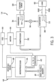
- the vapor compression system 14 may use one or more of a variable speed drive (VSDs) 52, a motor 50, the compressor 32, the condenser 34, the expansion valve or device 36, and/or the evaporator 38.
- the motor 50 may drive the compressor 32 and may be powered by a variable speed drive (VSD) 52.
- the VSD 52 receives alternating current (AC) power having a particular fixed line voltage and fixed line frequency from an AC power source, and provides power having a variable voltage and frequency to the motor 50.
- the motor 50 may be powered directly from an AC or direct current (DC) power source.
- the motor 50 may include any type of electric motor that can be powered by a VSD or directly from an AC or DC power source, such as a switched reluctance motor, an induction motor, an electronically commutated permanent magnet motor, or another suitable motor.
- the liquid refrigerant delivered to the evaporator 38 may absorb heat from another cooling fluid, which may or may not be the same cooling fluid used in the condenser 34.
- the liquid refrigerant in the evaporator 38 may undergo a phase change from the liquid refrigerant to a refrigerant vapor.
- the evaporator 38 may include a tube bundle 58 having a supply line 60S and a return line 60R connected to a cooling load 62.
- the cooling fluid of the evaporator 38 enters the evaporator 38 via return line 60R and exits the evaporator 38 via supply line 60S.
- the evaporator 38 may reduce the temperature of the cooling fluid in the tube bundle 58 via thermal heat transfer with the refrigerant.
- the tube bundle 58 in the evaporator 38 can include a plurality of tubes and/or a plurality of tube bundles. In any case, the vapor refrigerant exits the evaporator 38 and returns to the compressor 32 by a suction line to complete the cycle.
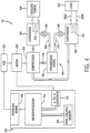
- FIG. 4 is a schematic of the vapor compression system 14 with an intermediate circuit 64 incorporated between condenser 34 and the expansion device 36.
- the intermediate circuit 64 may have an inlet line 68 that is directly fluidly connected to the condenser 34.
- the inlet line 68 may be indirectly fluidly coupled to the condenser 34.
- the inlet line 68 includes a first expansion device 66 positioned upstream of an intermediate vessel 70.
- the intermediate vessel 70 may be a flash tank (e.g., a flash intercooler).
- the intermediate vessel 70 may be configured as a heat exchanger or a "surface economizer.” In the illustrated embodiment of FIG.
- the intermediate vessel 70 is used as a flash tank, and the first expansion device 66 is configured to lower the pressure of (e.g., expand) the liquid refrigerant received from the condenser 34. During the expansion process, a portion of the liquid may vaporize, and thus, the intermediate vessel 70 may be used to separate the vapor from the liquid received from the first expansion device 66. Additionally, the intermediate vessel 70 may provide for further expansion of the liquid refrigerant because of a pressure drop experienced by the liquid refrigerant when entering the intermediate vessel 70 (e.g., due to a rapid increase in volume experienced when entering the intermediate vessel 70). The vapor in the intermediate vessel 70 may be drawn by the compressor 32 through a suction line 74 of the compressor 32.
- variable speed drive 52 that includes the silicon carbide transistor 100 achieves an improved efficiency over the variable speed drives that include a typical IGBT with a silicon diode.
- the variable speed drive 52 may improve an efficiency of the vapor compression system 14 between 0.25% and 3%, between 0.4% and 2%, or between 0.5% and 1.6%.
- the vapor compression system 14 may consume relatively large amounts of power.
- improvements in efficiency that are between 0.5% and 1.6% may significantly reduce an amount of power consumption by the vapor compression system 14, and thus, reduce operating costs of the vapor compression system 14.
- incorporating the silicon carbide transistor 100 into the variable speed drive 52 may improve the efficiency of the vapor compression system 14, and thus, reduce operating costs of the vapor compression system 14.
Landscapes
- Engineering & Computer Science (AREA)
- Power Engineering (AREA)
- Physics & Mathematics (AREA)
- Mechanical Engineering (AREA)
- Thermal Sciences (AREA)
- General Engineering & Computer Science (AREA)
- Inverter Devices (AREA)
- Control Of Ac Motors In General (AREA)
Claims (9)
- Système de chauffage, de ventilation, de climatisation et de réfrigération, CVCAR (10), comprenant :- un entraînement à vitesse variable (52) configuré pour fournir un courant à un moteur (50) configuré pour entraîner un compresseur (32) du système CVCAR (10), l'entraînement à vitesse variable comprenant :- un redresseur (102) configuré pour recevoir un courant alternatif, CA, provenant d'une source de courant CA (108) et convertir le courant alternatif, CA, en courant continu, CC, dans lequel le courant alternatif, CA, comprend une tension constante et une fréquence constante, le redresseur (102) comprenant un premier transistor en carbure de silicium (100) configuré pour régler une tension, ou une fréquence, ou les deux, du courant circulant à travers l'entraînement à vitesse variable (52) ;- un bus CC (104) configuré pour recevoir le courant continu provenant du redresseur (102) ; et- un onduleur (106) configuré pour recevoir le courant continu provenant du bus CC (104) et pour convertir le courant continu en courant alternatif ayant une tension et une fréquence variables, l'onduleur comprenant un second transistor en carbure de silicium (100) configuré pour régler la tension, ou la fréquence, ou les deux, du courant circulant à travers l'entraînement à vitesse variable (52) ; et- un dispositif de commande couplé à chaque transistor en carbure de silicium (100) et configuré pour régler un état des premier et second transistors en carbure de silicium (100) sur la base d'une pression de refoulement du compresseur (32).
- Système selon la revendication 1,
dans lequel le dispositif de commande est configuré pour régler l'état des premier et second transistors en carbure de silicium (100) sur la base de la vitesse du moteur (50) et de la pression de refoulement du compresseur (32). - Système selon la revendication 1 ou 2,
dans lequel le courant alternatif reçu de la source de courant alternatif (108) est un courant alternatif triphasé. - Système selon la revendication 3,
dans lequel le bus CC (104) est configuré pour recevoir le courant continu du redresseur (102) et pour filtrer ou stabiliser le courant continu. - Système selon l'une des revendications 1 à 4,
dans lequel les premier et second transistors en carbure de silicium (100) sont un transistor à effet de champ métal-oxyde-semiconducteur, MOSFET. - Système selon l'une des revendications 1 à 5, comprenant :- le compresseur (32) configuré pour faire circuler un fluide frigorigène à travers une boucle de fluide frigorigène du système CVCAR (10) ; et- un échangeur de chaleur configuré pour placer le fluide frigorigène en communication thermique avec un fluide de refroidissement.
- Système selon la revendication 6, comprenant un dispositif d'expansion (36, 66) configuré pour réduire la pression du fluide frigorigène circulant à travers la boucle de fluide frigorigène du système CVCAR (10).
- Procédé de fonctionnement du système selon l'une des revendications 1 à 7, comprenant :- la circulation d'un fluide frigorigène à travers une boucle de fluide frigorigène avec un compresseur (32) ;- le réglage d'une fréquence, ou d'une tension, ou des deux du courant dans l'entraînement à vitesse variable (52) à l'aide d'un transistor en carbure de silicium (100) ; et- la fourniture de courant à un moteur (50) avec un entraînement à vitesse variable (52), dans lequel le moteur (50) est configuré pour entraîner le compresseur (32), dans lequel l'entraînement à vitesse variable (52) comprend un redresseur (102) comprenant un premier transistor en carbure de silicium (100) et un onduleur (106) comprenant un second transistor en carbure de silicium (100), dans lequel le réglage de la fréquence, ou de la tension, ou des deux du courant dans l'entraînement à vitesse variable (52) à l'aide des premier et second transistors en carbure de silicium (100) comprend le réglage de la fréquence, ou de la tension, ou des deux du courant sur la base d'une pression de refoulement du compresseur (32).
- Procédé selon la revendication 8,
dans lequel le réglage de la fréquence, ou de la tension, ou des deux, comprend le réglage de la fréquence, ou de la tension, ou des deux du courant sur la base de la pression de refoulement du compresseur (32) et d'une vitesse du moteur (50).
Applications Claiming Priority (2)
| Application Number | Priority Date | Filing Date | Title |
|---|---|---|---|
| US201662404648P | 2016-10-05 | 2016-10-05 | |
| PCT/US2017/055381 WO2018067843A1 (fr) | 2016-10-05 | 2017-10-05 | Entraînement à vitesse variable pour un système cvcar |
Publications (2)
| Publication Number | Publication Date |
|---|---|
| EP3523874A1 EP3523874A1 (fr) | 2019-08-14 |
| EP3523874B1 true EP3523874B1 (fr) | 2025-07-09 |
Family
ID=60191464
Family Applications (1)
| Application Number | Title | Priority Date | Filing Date |
|---|---|---|---|
| EP17791780.4A Active EP3523874B1 (fr) | 2016-10-05 | 2017-10-05 | Entraînement à vitesse variable pour un système cvcar |
Country Status (7)
| Country | Link |
|---|---|
| US (1) | US10859300B2 (fr) |
| EP (1) | EP3523874B1 (fr) |
| JP (1) | JP2019533417A (fr) |
| KR (1) | KR102312058B1 (fr) |
| CN (1) | CN110326211A (fr) |
| TW (1) | TW201826689A (fr) |
| WO (1) | WO2018067843A1 (fr) |
Families Citing this family (4)
| Publication number | Priority date | Publication date | Assignee | Title |
|---|---|---|---|---|
| EP3659242A4 (fr) * | 2017-07-27 | 2021-04-14 | Flekkefjord Elektro AS | Moteur électrique à onduleur intégré |
| EP4281300A1 (fr) * | 2021-01-26 | 2023-11-29 | Dometic Sweden AB | Système de climatisation destiné à un véhicule |
| USD1073892S1 (en) | 2021-01-26 | 2025-05-06 | Dometic Sweden Ab | Air conditioning housing |
| WO2022193213A1 (fr) * | 2021-03-18 | 2022-09-22 | Johnson Controls Air Conditioning And Refrigeration (Wuxi) Co., Ltd. | Carte logique adaptative pour entraînement à vitesse variable pour système de chauffage, de ventilation, de climatisation et de réfrigération |
Citations (16)
| Publication number | Priority date | Publication date | Assignee | Title |
|---|---|---|---|---|
| EP0085285A1 (fr) | 1981-12-18 | 1983-08-10 | Institut Cerac S.A. | Système d'entraînement d'un compresseur |
| JP2008061414A (ja) | 2006-08-31 | 2008-03-13 | Daikin Ind Ltd | 電力変換装置 |
| JP2008061411A (ja) | 2006-08-31 | 2008-03-13 | Daikin Ind Ltd | 電力変換装置 |
| JP2008061404A (ja) | 2006-08-31 | 2008-03-13 | Daikin Ind Ltd | 電力変換装置 |
| WO2009058975A1 (fr) | 2007-10-31 | 2009-05-07 | Johnson Controls Technology Company | Système de commande |
| US7619906B2 (en) | 2005-03-01 | 2009-11-17 | York International Corporation | System for precharging a DC link in a variable speed drive |
| EP2169227A1 (fr) | 2007-06-06 | 2010-03-31 | Sanden Corporation | Dispositif de commande de compresseur électrique |
| WO2012012423A2 (fr) | 2010-07-20 | 2012-01-26 | Trane International Inc. | Compresseur à vis à capacité variable et procédé |
| EP2469201A2 (fr) | 2010-12-27 | 2012-06-27 | Mitsubishi Electric Corporation | Appareil de pompe à chaleur et son procédé de contrôle |
| EP2501030A2 (fr) | 2011-03-18 | 2012-09-19 | Mitsubishi Electric Corporation | Dispositif de commande d'inverseur et unité de climatisation et de réfrigération |
| US8336323B2 (en) | 2008-10-03 | 2012-12-25 | Johnson Controls Technology Company | Variable speed drive with pulse-width modulated speed control |
| WO2015140867A1 (fr) | 2014-03-15 | 2015-09-24 | 三菱電機株式会社 | Dispositif de commande d'entraînement de moteur, compresseur, ventilateur, et machine de conditionnement d'air |
| US20150318791A1 (en) | 2014-05-05 | 2015-11-05 | Rockwell Automation Technologies, Inc. | Motor drive with silicon carbide mosfet switches |
| WO2016027357A1 (fr) | 2014-08-22 | 2016-02-25 | 三菱電機株式会社 | Dispositif d'entraînement de moteur électrique et appareil de conditionnement d'air utilisant le dispositif d'entraînement de moteur électrique ou appareil de conditionnement d'air de réfrigération utilisant le dispositif d'entraînement de moteur électrique |
| EP3054585A1 (fr) | 2013-09-30 | 2016-08-10 | Mitsubishi Electric Corporation | Dispositif de commande d'entraînement de moteur, compresseur, ventilateur et dispositif de climatisation |
| US20160329851A1 (en) | 2015-05-08 | 2016-11-10 | Johnson Controls Technology Company | Variable speed drive with active converter |
Family Cites Families (34)
| Publication number | Priority date | Publication date | Assignee | Title |
|---|---|---|---|---|
| JP2001339975A (ja) * | 2000-05-25 | 2001-12-07 | Nikki Denso Kk | 3相モータ電源回生駆動 |
| JP2005016859A (ja) * | 2003-06-27 | 2005-01-20 | Mitsubishi Electric Corp | 空気調和装置 |
| US10594206B2 (en) | 2004-06-17 | 2020-03-17 | Hans Wennerstrom | High frequency inverter/distributed gap inductor—capacitor filter apparatus and method of use thereof |
| US9300197B2 (en) * | 2004-06-17 | 2016-03-29 | Grant A. MacLennan | High frequency inductor filter apparatus and method of use thereof |
| JP4494112B2 (ja) * | 2004-07-28 | 2010-06-30 | 三菱電機株式会社 | 空気調和装置のインバータ制御装置および空気調和装置 |
| US7555912B2 (en) | 2005-03-01 | 2009-07-07 | York International Corporation | System for precharging a DC link in a variable speed drive |
| FR2911736B1 (fr) | 2007-01-23 | 2009-03-20 | Schneider Toshiba Inverter | Dispositif de commande d'un interrupteur de puissance et variateur comprenant un tel dipositif. |
| FR2928058B1 (fr) | 2008-02-21 | 2010-02-19 | Schneider Toshiba Inverter | Variateur de vitesse incluant un dispositif de protection contre les surintensites et les surtensions. |
| FR2928056B1 (fr) | 2008-02-21 | 2010-02-19 | Schneider Toshiba Inverter | Dispositif de protection d'un variateur de vitesse contre les surintensites. |
| FR2928057B1 (fr) | 2008-02-21 | 2012-06-01 | Schneider Toshiba Inverter | Dispositif de protection d'un variateur de vitesse incluant une inductance de filtrage. |
| JP4937281B2 (ja) * | 2009-01-16 | 2012-05-23 | 三菱電機株式会社 | モーター駆動制御装置、圧縮機、送風機、空気調和機及び冷蔵庫又は冷凍庫 |
| US8299646B2 (en) * | 2009-07-27 | 2012-10-30 | Rocky Research | HVAC/R system with variable frequency drive (VFD) power supply for multiple motors |
| US8193660B2 (en) * | 2009-07-27 | 2012-06-05 | Rocky Research | HVAC/R system having power back-up system with a DC-DC converter |
| FR2951333B1 (fr) * | 2009-10-08 | 2011-10-28 | Schneider Electric Ind Sas | Convertisseur de puissance utilisant des transistors a effet de champ normalement fermes |
| WO2012029099A1 (fr) | 2010-08-30 | 2012-03-08 | 三菱電機株式会社 | Dispositif de pompe à chaleur, système de pompe à chaleur et procédé de commande d'un onduleur triphasé |
| US9543887B2 (en) | 2010-10-15 | 2017-01-10 | Mitsubishi Electric Corporation | Heat pump device, heat pump system, and method for controlling three-phase inverter |
| JP5490260B2 (ja) | 2010-12-21 | 2014-05-14 | 三菱電機株式会社 | ヒートポンプ装置、ヒートポンプシステム及びインバータの制御方法 |
| US9228750B2 (en) * | 2011-01-24 | 2016-01-05 | Rocky Research | HVAC/R system with multiple power sources and time-based selection logic |
| WO2012107987A1 (fr) | 2011-02-07 | 2012-08-16 | 三菱電機株式会社 | Dispositif de pompe à chaleur, système de pompe à chaleur, et procédé de commande pour convertisseur triphasé |
| US9829226B2 (en) | 2011-04-28 | 2017-11-28 | Mitsubishi Electric Corporation | Heat pump device, heat pump system, and method for controlling inverter |
| WO2013046454A1 (fr) | 2011-09-30 | 2013-04-04 | 三菱電機株式会社 | Dispositif de pompe à chaleur, système de pompe à chaleur et procédé de commande d'onduleur |
| JP5937619B2 (ja) | 2011-12-14 | 2016-06-22 | 三菱電機株式会社 | ヒートポンプ装置ならびに、それを備えた空気調和機、ヒートポンプ給湯機、冷蔵庫、および冷凍機 |
| US10605500B2 (en) | 2012-01-04 | 2020-03-31 | Mitsubishi Electric Corporation | Heat pump device, air conditioner, and freezer |
| WO2013157074A1 (fr) | 2012-04-16 | 2013-10-24 | 三菱電機株式会社 | Dispositif de pompe à chaleur, appareil de conditionnement d'air et machine de refroidissement |
| WO2013190665A1 (fr) | 2012-06-20 | 2013-12-27 | 三菱電機株式会社 | Dispositif de pompe à chaleur, conditionneur d'air et machine frigorifique |
| US9746216B2 (en) | 2012-06-29 | 2017-08-29 | Mitsubishi Electric Corporation | Heat pump device, heat pump system, air conditioner, and freezer |
| WO2014113777A1 (fr) * | 2013-01-21 | 2014-07-24 | Trane International Inc. | Pilotes de compresseur de réfrigérant offrant robustesse, efficacité et opérabilité sous tension nominale améliorées |
| CN105209835B (zh) | 2013-05-23 | 2017-05-24 | 三菱电机株式会社 | 热泵装置及具有其的空调机、热泵式热水器、冰箱和制冷机 |
| WO2015056341A1 (fr) * | 2013-10-18 | 2015-04-23 | 三菱電機株式会社 | Dispositif source d'alimentation en c.c., dispositif d'entrainement de moteur, climatiseur et refrigerateur |
| JP2015084622A (ja) | 2013-10-25 | 2015-04-30 | 三菱重工オートモーティブサーマルシステムズ株式会社 | スイッチング素子の駆動装置及び駆動方法並びに車両用空調装置 |
| CN105981277B (zh) * | 2014-02-19 | 2019-04-23 | 三菱电机株式会社 | 直流电源装置、电动机驱动装置和制冷循环应用设备 |
| JP6333395B2 (ja) | 2014-09-26 | 2018-05-30 | 三菱電機株式会社 | ヒートポンプ装置ならびに、それを備えた空気調和機、ヒートポンプ給湯機、冷蔵庫、および冷凍機 |
| WO2016071965A1 (fr) * | 2014-11-04 | 2016-05-12 | 三菱電機株式会社 | Appareil pompe à chaleur ainsi que climatiseur, chauffe-eau à pompe à chaleur et réfrigérateur pourvus de celui-ci |
| US9859808B2 (en) | 2016-04-26 | 2018-01-02 | General Electric Company | Power converter topology for use in an energy storage system |
-
2017
- 2017-10-05 EP EP17791780.4A patent/EP3523874B1/fr active Active
- 2017-10-05 CN CN201780061782.1A patent/CN110326211A/zh active Pending
- 2017-10-05 WO PCT/US2017/055381 patent/WO2018067843A1/fr not_active Ceased
- 2017-10-05 US US16/339,332 patent/US10859300B2/en active Active
- 2017-10-05 JP JP2019518113A patent/JP2019533417A/ja active Pending
- 2017-10-05 TW TW106134382A patent/TW201826689A/zh unknown
- 2017-10-05 KR KR1020197012500A patent/KR102312058B1/ko active Active
Patent Citations (18)
| Publication number | Priority date | Publication date | Assignee | Title |
|---|---|---|---|---|
| EP0085285A1 (fr) | 1981-12-18 | 1983-08-10 | Institut Cerac S.A. | Système d'entraînement d'un compresseur |
| US7619906B2 (en) | 2005-03-01 | 2009-11-17 | York International Corporation | System for precharging a DC link in a variable speed drive |
| JP2008061414A (ja) | 2006-08-31 | 2008-03-13 | Daikin Ind Ltd | 電力変換装置 |
| JP2008061411A (ja) | 2006-08-31 | 2008-03-13 | Daikin Ind Ltd | 電力変換装置 |
| JP2008061404A (ja) | 2006-08-31 | 2008-03-13 | Daikin Ind Ltd | 電力変換装置 |
| EP2169227A1 (fr) | 2007-06-06 | 2010-03-31 | Sanden Corporation | Dispositif de commande de compresseur électrique |
| WO2009058975A1 (fr) | 2007-10-31 | 2009-05-07 | Johnson Controls Technology Company | Système de commande |
| US8336323B2 (en) | 2008-10-03 | 2012-12-25 | Johnson Controls Technology Company | Variable speed drive with pulse-width modulated speed control |
| WO2012012423A2 (fr) | 2010-07-20 | 2012-01-26 | Trane International Inc. | Compresseur à vis à capacité variable et procédé |
| EP2469201A2 (fr) | 2010-12-27 | 2012-06-27 | Mitsubishi Electric Corporation | Appareil de pompe à chaleur et son procédé de contrôle |
| EP2501030A2 (fr) | 2011-03-18 | 2012-09-19 | Mitsubishi Electric Corporation | Dispositif de commande d'inverseur et unité de climatisation et de réfrigération |
| EP3054585A1 (fr) | 2013-09-30 | 2016-08-10 | Mitsubishi Electric Corporation | Dispositif de commande d'entraînement de moteur, compresseur, ventilateur et dispositif de climatisation |
| WO2015140867A1 (fr) | 2014-03-15 | 2015-09-24 | 三菱電機株式会社 | Dispositif de commande d'entraînement de moteur, compresseur, ventilateur, et machine de conditionnement d'air |
| US20160380575A1 (en) | 2014-03-15 | 2016-12-29 | Mitsubishi Electric Corporation | Motor drive control device, compressor, air-sending device, and air-conditioning apparatus |
| US20150318791A1 (en) | 2014-05-05 | 2015-11-05 | Rockwell Automation Technologies, Inc. | Motor drive with silicon carbide mosfet switches |
| WO2016027357A1 (fr) | 2014-08-22 | 2016-02-25 | 三菱電機株式会社 | Dispositif d'entraînement de moteur électrique et appareil de conditionnement d'air utilisant le dispositif d'entraînement de moteur électrique ou appareil de conditionnement d'air de réfrigération utilisant le dispositif d'entraînement de moteur électrique |
| US20170138654A1 (en) | 2014-08-22 | 2017-05-18 | Mitsubishi Electric Corporation | Electric motor drive device and air-conditioning apparatus or refrigerating and air-conditioning apparatus using the same |
| US20160329851A1 (en) | 2015-05-08 | 2016-11-10 | Johnson Controls Technology Company | Variable speed drive with active converter |
Non-Patent Citations (7)
| Title |
|---|
| "Intelligent Buildings and Building Automation", 4 December 2009, CRC PRESS LLC, article WANG SHENGWEI: "9 Control and optimization of central chilling systems", pages: 175 - 206, XP055834362 * |
| ANONYMOUS: "Clausius-Clapeyron-Gleichung", WIKIPEDIA, pages 1 - 3, XP093386895, Retrieved from the Internet <URL:https://de.wikipedia.org/w/index.php?title=Clausius-Clapeyron-Gleichung&oldid=155193103> |
| CAUSEY ANDREW E.: "COMPRESSOR LOAD STAND: COMMISSIONING AND CONTROL STRATEGIES", THESIS, PURDUE UNIVERSITY, pages 1 - 112, XP093386900, Retrieved from the Internet <URL:https://apps.dtic.mil/sti/tr/pdf/ADA356197.pdf> |
| KORN, DIETER: "Effizienter Betrieb von Kälteanlagen", 1 September 2014, VDE VERLAG GMBH, ISBN: 978-3-8007-3593-8, article KORN, DIETER: "2 Drehzahlverstellung zur bedarfsabhängigen Regelung von Verdichtern und Verflüssiger-Ventilatoren", pages: 9 - 32, XP009566400 |
| ORELLANA RACCOURSIER ALVARO: "Kompakter rückspeisefähiger Antriebsstromrichter mit SiC-JFETs und sinusförmigen Ausgangsspannungen", UNIVERSITÄT ERLANGEN, pages 1 - 245, XP093386906, ISBN: 978-3-86955-007-7, Retrieved from the Internet <URL:https://cuvillier.de/de/shop/publications/1101-kompakter-ruckspeisefahiger-antriebsstromrichter-mit-sic-jfets-und-sinusformigen-ausgangsspannungen> |
| TRINTIS IONUT, DOUGLASS PHILIP, MAHESHWARI RAMKRISHAN, MUNK-NIELSEN STIG: "SiC heat pump converters with support for voltage unbalance in distribution grids", 2015 17TH EUROPEAN CONFERENCE ON POWER ELECTRONICS AND APPLICATIONS (EPE'15 ECCE-EUROPE), IEEE, 1 September 2015 (2015-09-01) - 2015-09-10, pages 1 - 7, XP093384440, ISBN: 978-1-4799-8277-6, DOI: 10.1109/epe.2015.7311670 |
| XUE, Z. ; SHI, L.: "Modeling and Experimental Investigation of a Variable Speed Drive Water Source Heat Pump", TSINGHUA SCIENCE AND TECHNOLOGY, TSINGHUA UNIVERSITY PRESS, BEIJING, CN, vol. 15, no. 4, 1 August 2010 (2010-08-01), CN , pages 434 - 440, XP027188471, ISSN: 1007-0214 |
Also Published As
| Publication number | Publication date |
|---|---|
| US10859300B2 (en) | 2020-12-08 |
| CN110326211A (zh) | 2019-10-11 |
| KR102312058B1 (ko) | 2021-10-14 |
| TW201826689A (zh) | 2018-07-16 |
| WO2018067843A1 (fr) | 2018-04-12 |
| JP2019533417A (ja) | 2019-11-14 |
| KR20190054170A (ko) | 2019-05-21 |
| US20200041185A1 (en) | 2020-02-06 |
| EP3523874A1 (fr) | 2019-08-14 |
Similar Documents
| Publication | Publication Date | Title |
|---|---|---|
| EP2763303B1 (fr) | Dispositif de pompe à chaleur, système de pompe à chaleur et procédé de commande d'onduleur | |
| EP2629029B1 (fr) | Dispositif de pompe à chaleur, système de pompe à chaleur, et procédé de commande d'un convertisseur triphasé | |
| AU2012377681B2 (en) | Heat pump device, air conditioner, and cooling machine | |
| CN104321596B (zh) | 热泵装置、空调机和制冷机 | |
| EP2674694A1 (fr) | Dispositif de pompe à chaleur, système de pompe à chaleur, et procédé de commande pour convertisseur triphasé | |
| CN106461278B (zh) | 运行冷却器的方法 | |
| EP3523874B1 (fr) | Entraînement à vitesse variable pour un système cvcar | |
| US11486612B2 (en) | Heat pump for a HVACandR system | |
| US10812005B2 (en) | Variable speed drive with a battery | |
| US9631852B2 (en) | System and method for controlling compressor motor voltage | |
| CN105980795A (zh) | 用于制冷系统的电机和驱动器布置 | |
| WO2017120503A1 (fr) | Système de compression de vapeur | |
| CN105829810A (zh) | 具有两相回路的级联空调系统的操作 | |
| JP7421473B2 (ja) | デュアル電源可変速駆動装置のためのシステム及び方法 | |
| US20220252306A1 (en) | Series flow chiller system | |
| JP2015224802A (ja) | 冷凍装置 |
Legal Events
| Date | Code | Title | Description |
|---|---|---|---|
| STAA | Information on the status of an ep patent application or granted ep patent |
Free format text: STATUS: UNKNOWN |
|
| STAA | Information on the status of an ep patent application or granted ep patent |
Free format text: STATUS: THE INTERNATIONAL PUBLICATION HAS BEEN MADE |
|
| PUAI | Public reference made under article 153(3) epc to a published international application that has entered the european phase |
Free format text: ORIGINAL CODE: 0009012 |
|
| STAA | Information on the status of an ep patent application or granted ep patent |
Free format text: STATUS: REQUEST FOR EXAMINATION WAS MADE |
|
| 17P | Request for examination filed |
Effective date: 20190402 |
|
| AK | Designated contracting states |
Kind code of ref document: A1 Designated state(s): AL AT BE BG CH CY CZ DE DK EE ES FI FR GB GR HR HU IE IS IT LI LT LU LV MC MK MT NL NO PL PT RO RS SE SI SK SM TR |
|
| AX | Request for extension of the european patent |
Extension state: BA ME |
|
| DAV | Request for validation of the european patent (deleted) | ||
| DAX | Request for extension of the european patent (deleted) | ||
| STAA | Information on the status of an ep patent application or granted ep patent |
Free format text: STATUS: EXAMINATION IS IN PROGRESS |
|
| 17Q | First examination report despatched |
Effective date: 20200429 |
|
| RAP1 | Party data changed (applicant data changed or rights of an application transferred) |
Owner name: JOHNSON CONTROLS TYCO IP HOLDINGS LLP |
|
| GRAP | Despatch of communication of intention to grant a patent |
Free format text: ORIGINAL CODE: EPIDOSNIGR1 |
|
| STAA | Information on the status of an ep patent application or granted ep patent |
Free format text: STATUS: GRANT OF PATENT IS INTENDED |
|
| RIC1 | Information provided on ipc code assigned before grant |
Ipc: F25B 49/02 20060101ALI20250127BHEP Ipc: H02M 5/458 20060101ALI20250127BHEP Ipc: H02P 27/16 20060101ALI20250127BHEP Ipc: H02P 27/04 20160101AFI20250127BHEP |
|
| INTG | Intention to grant announced |
Effective date: 20250205 |
|
| GRAS | Grant fee paid |
Free format text: ORIGINAL CODE: EPIDOSNIGR3 |
|
| GRAA | (expected) grant |
Free format text: ORIGINAL CODE: 0009210 |
|
| STAA | Information on the status of an ep patent application or granted ep patent |
Free format text: STATUS: THE PATENT HAS BEEN GRANTED |
|
| AK | Designated contracting states |
Kind code of ref document: B1 Designated state(s): AL AT BE BG CH CY CZ DE DK EE ES FI FR GB GR HR HU IE IS IT LI LT LU LV MC MK MT NL NO PL PT RO RS SE SI SK SM TR |
|
| REG | Reference to a national code |
Ref country code: GB Ref legal event code: FG4D |
|
| REG | Reference to a national code |
Ref country code: CH Ref legal event code: EP |
|
| REG | Reference to a national code |
Ref country code: IE Ref legal event code: FG4D |
|
| REG | Reference to a national code |
Ref country code: DE Ref legal event code: R096 Ref document number: 602017090470 Country of ref document: DE |
|
| REG | Reference to a national code |
Ref country code: NL Ref legal event code: MP Effective date: 20250709 |
|
| PG25 | Lapsed in a contracting state [announced via postgrant information from national office to epo] |
Ref country code: PT Free format text: LAPSE BECAUSE OF FAILURE TO SUBMIT A TRANSLATION OF THE DESCRIPTION OR TO PAY THE FEE WITHIN THE PRESCRIBED TIME-LIMIT Effective date: 20251110 |
|
| PG25 | Lapsed in a contracting state [announced via postgrant information from national office to epo] |
Ref country code: NL Free format text: LAPSE BECAUSE OF FAILURE TO SUBMIT A TRANSLATION OF THE DESCRIPTION OR TO PAY THE FEE WITHIN THE PRESCRIBED TIME-LIMIT Effective date: 20250709 |
|
| REG | Reference to a national code |
Ref country code: AT Ref legal event code: MK05 Ref document number: 1812842 Country of ref document: AT Kind code of ref document: T Effective date: 20250709 |
|
| PG25 | Lapsed in a contracting state [announced via postgrant information from national office to epo] |
Ref country code: IS Free format text: LAPSE BECAUSE OF FAILURE TO SUBMIT A TRANSLATION OF THE DESCRIPTION OR TO PAY THE FEE WITHIN THE PRESCRIBED TIME-LIMIT Effective date: 20251109 |
|
| PGFP | Annual fee paid to national office [announced via postgrant information from national office to epo] |
Ref country code: DE Payment date: 20251028 Year of fee payment: 9 |
|
| PG25 | Lapsed in a contracting state [announced via postgrant information from national office to epo] |
Ref country code: NO Free format text: LAPSE BECAUSE OF FAILURE TO SUBMIT A TRANSLATION OF THE DESCRIPTION OR TO PAY THE FEE WITHIN THE PRESCRIBED TIME-LIMIT Effective date: 20251009 |
|
| REG | Reference to a national code |
Ref country code: LT Ref legal event code: MG9D |
|
| PG25 | Lapsed in a contracting state [announced via postgrant information from national office to epo] |
Ref country code: AT Free format text: LAPSE BECAUSE OF FAILURE TO SUBMIT A TRANSLATION OF THE DESCRIPTION OR TO PAY THE FEE WITHIN THE PRESCRIBED TIME-LIMIT Effective date: 20250709 |
|
| PG25 | Lapsed in a contracting state [announced via postgrant information from national office to epo] |
Ref country code: FI Free format text: LAPSE BECAUSE OF FAILURE TO SUBMIT A TRANSLATION OF THE DESCRIPTION OR TO PAY THE FEE WITHIN THE PRESCRIBED TIME-LIMIT Effective date: 20250709 |
|
| PG25 | Lapsed in a contracting state [announced via postgrant information from national office to epo] |
Ref country code: HR Free format text: LAPSE BECAUSE OF FAILURE TO SUBMIT A TRANSLATION OF THE DESCRIPTION OR TO PAY THE FEE WITHIN THE PRESCRIBED TIME-LIMIT Effective date: 20250709 |
|
| PGFP | Annual fee paid to national office [announced via postgrant information from national office to epo] |
Ref country code: FR Payment date: 20251027 Year of fee payment: 9 |
|
| PG25 | Lapsed in a contracting state [announced via postgrant information from national office to epo] |
Ref country code: GR Free format text: LAPSE BECAUSE OF FAILURE TO SUBMIT A TRANSLATION OF THE DESCRIPTION OR TO PAY THE FEE WITHIN THE PRESCRIBED TIME-LIMIT Effective date: 20251010 |
|
| PG25 | Lapsed in a contracting state [announced via postgrant information from national office to epo] |
Ref country code: SE Free format text: LAPSE BECAUSE OF FAILURE TO SUBMIT A TRANSLATION OF THE DESCRIPTION OR TO PAY THE FEE WITHIN THE PRESCRIBED TIME-LIMIT Effective date: 20250709 |
|
| PG25 | Lapsed in a contracting state [announced via postgrant information from national office to epo] |
Ref country code: LV Free format text: LAPSE BECAUSE OF FAILURE TO SUBMIT A TRANSLATION OF THE DESCRIPTION OR TO PAY THE FEE WITHIN THE PRESCRIBED TIME-LIMIT Effective date: 20250709 |
|
| PG25 | Lapsed in a contracting state [announced via postgrant information from national office to epo] |
Ref country code: PL Free format text: LAPSE BECAUSE OF FAILURE TO SUBMIT A TRANSLATION OF THE DESCRIPTION OR TO PAY THE FEE WITHIN THE PRESCRIBED TIME-LIMIT Effective date: 20250709 Ref country code: BG Free format text: LAPSE BECAUSE OF FAILURE TO SUBMIT A TRANSLATION OF THE DESCRIPTION OR TO PAY THE FEE WITHIN THE PRESCRIBED TIME-LIMIT Effective date: 20250709 |
|
| PG25 | Lapsed in a contracting state [announced via postgrant information from national office to epo] |
Ref country code: RS Free format text: LAPSE BECAUSE OF FAILURE TO SUBMIT A TRANSLATION OF THE DESCRIPTION OR TO PAY THE FEE WITHIN THE PRESCRIBED TIME-LIMIT Effective date: 20251009 |
|
| PG25 | Lapsed in a contracting state [announced via postgrant information from national office to epo] |
Ref country code: ES Free format text: LAPSE BECAUSE OF FAILURE TO SUBMIT A TRANSLATION OF THE DESCRIPTION OR TO PAY THE FEE WITHIN THE PRESCRIBED TIME-LIMIT Effective date: 20250709 |
|
| PG25 | Lapsed in a contracting state [announced via postgrant information from national office to epo] |
Ref country code: RO Free format text: LAPSE BECAUSE OF FAILURE TO SUBMIT A TRANSLATION OF THE DESCRIPTION OR TO PAY THE FEE WITHIN THE PRESCRIBED TIME-LIMIT Effective date: 20250709 |
|
| REG | Reference to a national code |
Ref country code: DE Ref legal event code: R026 Ref document number: 602017090470 Country of ref document: DE |
|
| PLBI | Opposition filed |
Free format text: ORIGINAL CODE: 0009260 |
|
| PG25 | Lapsed in a contracting state [announced via postgrant information from national office to epo] |
Ref country code: SM Free format text: LAPSE BECAUSE OF FAILURE TO SUBMIT A TRANSLATION OF THE DESCRIPTION OR TO PAY THE FEE WITHIN THE PRESCRIBED TIME-LIMIT Effective date: 20250709 |
|
| REG | Reference to a national code |
Ref country code: CH Ref legal event code: L10 Free format text: ST27 STATUS EVENT CODE: U-0-0-L10-L00 (AS PROVIDED BY THE NATIONAL OFFICE) Effective date: 20260409 |
|
| PLBI | Opposition filed |
Free format text: ORIGINAL CODE: 0009260 |
|
| PG25 | Lapsed in a contracting state [announced via postgrant information from national office to epo] |
Ref country code: DK Free format text: LAPSE BECAUSE OF FAILURE TO SUBMIT A TRANSLATION OF THE DESCRIPTION OR TO PAY THE FEE WITHIN THE PRESCRIBED TIME-LIMIT Effective date: 20250709 |
|
| PG25 | Lapsed in a contracting state [announced via postgrant information from national office to epo] |
Ref country code: IT Free format text: LAPSE BECAUSE OF FAILURE TO SUBMIT A TRANSLATION OF THE DESCRIPTION OR TO PAY THE FEE WITHIN THE PRESCRIBED TIME-LIMIT Effective date: 20250709 |
|
| REG | Reference to a national code |
Ref country code: CH Ref legal event code: L10 Free format text: ST27 STATUS EVENT CODE: U-0-0-L10-L00 (AS PROVIDED BY THE NATIONAL OFFICE) Effective date: 20260416 |
|
| PLAX | Notice of opposition and request to file observation + time limit sent |
Free format text: ORIGINAL CODE: EPIDOSNOBS2 |
|
| PG25 | Lapsed in a contracting state [announced via postgrant information from national office to epo] |
Ref country code: CZ Free format text: LAPSE BECAUSE OF FAILURE TO SUBMIT A TRANSLATION OF THE DESCRIPTION OR TO PAY THE FEE WITHIN THE PRESCRIBED TIME-LIMIT Effective date: 20250709 |
|
| PG25 | Lapsed in a contracting state [announced via postgrant information from national office to epo] |
Ref country code: EE Free format text: LAPSE BECAUSE OF FAILURE TO SUBMIT A TRANSLATION OF THE DESCRIPTION OR TO PAY THE FEE WITHIN THE PRESCRIBED TIME-LIMIT Effective date: 20250709 Ref country code: SK Free format text: LAPSE BECAUSE OF FAILURE TO SUBMIT A TRANSLATION OF THE DESCRIPTION OR TO PAY THE FEE WITHIN THE PRESCRIBED TIME-LIMIT Effective date: 20250709 |