EP3524162A1 - Drahtlose ultraschallsonde und an die drahtlose ultraschallsonde angeschlossene ultraschallbildgebungsvorrichtung - Google Patents
Drahtlose ultraschallsonde und an die drahtlose ultraschallsonde angeschlossene ultraschallbildgebungsvorrichtung Download PDFInfo
- Publication number
- EP3524162A1 EP3524162A1 EP19153782.8A EP19153782A EP3524162A1 EP 3524162 A1 EP3524162 A1 EP 3524162A1 EP 19153782 A EP19153782 A EP 19153782A EP 3524162 A1 EP3524162 A1 EP 3524162A1
- Authority
- EP
- European Patent Office
- Prior art keywords
- ultrasound probe
- wireless
- imaging apparatus
- wireless ultrasound
- power supply
- Prior art date
- Legal status (The legal status is an assumption and is not a legal conclusion. Google has not performed a legal analysis and makes no representation as to the accuracy of the status listed.)
- Granted
Links
Images









Classifications
-
- A—HUMAN NECESSITIES
- A61—MEDICAL OR VETERINARY SCIENCE; HYGIENE
- A61B—DIAGNOSIS; SURGERY; IDENTIFICATION
- A61B8/00—Diagnosis using ultrasonic, sonic or infrasonic waves
- A61B8/44—Constructional features of the ultrasonic, sonic or infrasonic diagnostic device
- A61B8/4444—Constructional features of the ultrasonic, sonic or infrasonic diagnostic device related to the probe
- A61B8/4472—Wireless probes
-
- A—HUMAN NECESSITIES
- A61—MEDICAL OR VETERINARY SCIENCE; HYGIENE
- A61B—DIAGNOSIS; SURGERY; IDENTIFICATION
- A61B8/00—Diagnosis using ultrasonic, sonic or infrasonic waves
- A61B8/44—Constructional features of the ultrasonic, sonic or infrasonic diagnostic device
- A61B8/4433—Constructional features of the ultrasonic, sonic or infrasonic diagnostic device involving a docking unit
-
- A—HUMAN NECESSITIES
- A61—MEDICAL OR VETERINARY SCIENCE; HYGIENE
- A61B—DIAGNOSIS; SURGERY; IDENTIFICATION
- A61B8/00—Diagnosis using ultrasonic, sonic or infrasonic waves
- A61B8/44—Constructional features of the ultrasonic, sonic or infrasonic diagnostic device
- A61B8/4438—Means for identifying the diagnostic device, e.g. barcodes
-
- A—HUMAN NECESSITIES
- A61—MEDICAL OR VETERINARY SCIENCE; HYGIENE
- A61B—DIAGNOSIS; SURGERY; IDENTIFICATION
- A61B8/00—Diagnosis using ultrasonic, sonic or infrasonic waves
- A61B8/46—Ultrasonic, sonic or infrasonic diagnostic devices with special arrangements for interfacing with the operator or the patient
- A61B8/461—Displaying means of special interest
-
- A—HUMAN NECESSITIES
- A61—MEDICAL OR VETERINARY SCIENCE; HYGIENE
- A61B—DIAGNOSIS; SURGERY; IDENTIFICATION
- A61B8/00—Diagnosis using ultrasonic, sonic or infrasonic waves
- A61B8/46—Ultrasonic, sonic or infrasonic diagnostic devices with special arrangements for interfacing with the operator or the patient
- A61B8/467—Ultrasonic, sonic or infrasonic diagnostic devices with special arrangements for interfacing with the operator or the patient characterised by special input means
-
- A—HUMAN NECESSITIES
- A61—MEDICAL OR VETERINARY SCIENCE; HYGIENE
- A61B—DIAGNOSIS; SURGERY; IDENTIFICATION
- A61B8/00—Diagnosis using ultrasonic, sonic or infrasonic waves
- A61B8/54—Control of the diagnostic device
-
- A—HUMAN NECESSITIES
- A61—MEDICAL OR VETERINARY SCIENCE; HYGIENE
- A61B—DIAGNOSIS; SURGERY; IDENTIFICATION
- A61B8/00—Diagnosis using ultrasonic, sonic or infrasonic waves
- A61B8/56—Details of data transmission or power supply
-
- G—PHYSICS
- G06—COMPUTING OR CALCULATING; COUNTING
- G06V—IMAGE OR VIDEO RECOGNITION OR UNDERSTANDING
- G06V40/00—Recognition of biometric, human-related or animal-related patterns in image or video data
- G06V40/10—Human or animal bodies, e.g. vehicle occupants or pedestrians; Body parts, e.g. hands
- G06V40/12—Fingerprints or palmprints
- G06V40/1365—Matching; Classification
-
- G—PHYSICS
- G06—COMPUTING OR CALCULATING; COUNTING
- G06V—IMAGE OR VIDEO RECOGNITION OR UNDERSTANDING
- G06V40/00—Recognition of biometric, human-related or animal-related patterns in image or video data
- G06V40/10—Human or animal bodies, e.g. vehicle occupants or pedestrians; Body parts, e.g. hands
- G06V40/16—Human faces, e.g. facial parts, sketches or expressions
- G06V40/172—Classification, e.g. identification
-
- G—PHYSICS
- G06—COMPUTING OR CALCULATING; COUNTING
- G06V—IMAGE OR VIDEO RECOGNITION OR UNDERSTANDING
- G06V40/00—Recognition of biometric, human-related or animal-related patterns in image or video data
- G06V40/10—Human or animal bodies, e.g. vehicle occupants or pedestrians; Body parts, e.g. hands
- G06V40/18—Eye characteristics, e.g. of the iris
- G06V40/197—Matching; Classification
-
- H—ELECTRICITY
- H02—GENERATION; CONVERSION OR DISTRIBUTION OF ELECTRIC POWER
- H02J—ELECTRIC POWER NETWORKS; CIRCUIT ARRANGEMENTS OR SYSTEMS FOR SUPPLYING OR DISTRIBUTING ELECTRIC POWER; SYSTEMS FOR STORING ELECTRIC ENERGY
- H02J7/00—Circuit arrangements for charging or discharging batteries or for supplying loads from batteries
- H02J7/70—Circuit arrangements for charging or discharging batteries or for supplying loads from batteries characterised by the mechanical construction
-
- H—ELECTRICITY
- H02—GENERATION; CONVERSION OR DISTRIBUTION OF ELECTRIC POWER
- H02J—ELECTRIC POWER NETWORKS; CIRCUIT ARRANGEMENTS OR SYSTEMS FOR SUPPLYING OR DISTRIBUTING ELECTRIC POWER; SYSTEMS FOR STORING ELECTRIC ENERGY
- H02J7/00—Circuit arrangements for charging or discharging batteries or for supplying loads from batteries
- H02J7/70—Circuit arrangements for charging or discharging batteries or for supplying loads from batteries characterised by the mechanical construction
- H02J7/751—Circuit arrangements for charging or discharging batteries or for supplying loads from batteries characterised by the mechanical construction concerning the insertion or the connection of the batteries
-
- A—HUMAN NECESSITIES
- A61—MEDICAL OR VETERINARY SCIENCE; HYGIENE
- A61B—DIAGNOSIS; SURGERY; IDENTIFICATION
- A61B8/00—Diagnosis using ultrasonic, sonic or infrasonic waves
- A61B8/44—Constructional features of the ultrasonic, sonic or infrasonic diagnostic device
- A61B8/4405—Device being mounted on a trolley
-
- A—HUMAN NECESSITIES
- A61—MEDICAL OR VETERINARY SCIENCE; HYGIENE
- A61B—DIAGNOSIS; SURGERY; IDENTIFICATION
- A61B8/00—Diagnosis using ultrasonic, sonic or infrasonic waves
- A61B8/44—Constructional features of the ultrasonic, sonic or infrasonic diagnostic device
- A61B8/4427—Device being portable or laptop-like
-
- A—HUMAN NECESSITIES
- A61—MEDICAL OR VETERINARY SCIENCE; HYGIENE
- A61B—DIAGNOSIS; SURGERY; IDENTIFICATION
- A61B8/00—Diagnosis using ultrasonic, sonic or infrasonic waves
- A61B8/46—Ultrasonic, sonic or infrasonic diagnostic devices with special arrangements for interfacing with the operator or the patient
- A61B8/461—Displaying means of special interest
- A61B8/463—Displaying means of special interest characterised by displaying multiple images or images and diagnostic data on one display
-
- A—HUMAN NECESSITIES
- A61—MEDICAL OR VETERINARY SCIENCE; HYGIENE
- A61B—DIAGNOSIS; SURGERY; IDENTIFICATION
- A61B8/00—Diagnosis using ultrasonic, sonic or infrasonic waves
- A61B8/46—Ultrasonic, sonic or infrasonic diagnostic devices with special arrangements for interfacing with the operator or the patient
- A61B8/461—Displaying means of special interest
- A61B8/465—Displaying means of special interest adapted to display user selection data, e.g. icons or menus
-
- G—PHYSICS
- G01—MEASURING; TESTING
- G01S—RADIO DIRECTION-FINDING; RADIO NAVIGATION; DETERMINING DISTANCE OR VELOCITY BY USE OF RADIO WAVES; LOCATING OR PRESENCE-DETECTING BY USE OF THE REFLECTION OR RERADIATION OF RADIO WAVES; ANALOGOUS ARRANGEMENTS USING OTHER WAVES
- G01S7/00—Details of systems according to groups G01S13/00, G01S15/00, G01S17/00
- G01S7/52—Details of systems according to groups G01S13/00, G01S15/00, G01S17/00 of systems according to group G01S15/00
- G01S7/52017—Details of systems according to groups G01S13/00, G01S15/00, G01S17/00 of systems according to group G01S15/00 particularly adapted to short-range imaging
- G01S7/52096—Details of systems according to groups G01S13/00, G01S15/00, G01S17/00 of systems according to group G01S15/00 particularly adapted to short-range imaging related to power management, e.g. saving power or prolonging life of electronic components
Definitions
- the disclosure relates to wireless ultrasound probes and ultrasound imaging apparatuses connected with the wireless ultrasound probes, and more particularly, to wireless ultrasound probes including a physical coupling device having a unique shape for theft prevention and ultrasound imaging apparatuses that are connected with the wireless ultrasound probes and supply a charging power thereto.
- Ultrasound systems transmit ultrasound signals generated by transducers of an ultrasound probe to an internal part of an object and receive information about echo signals reflected therefrom, thereby obtaining an image of the internal part of the object.
- ultrasound systems are used for medical purposes including observation of an internal area of an object, detection of foreign substances, diagnosis of damage to the object, and imaging of characteristics.
- Wireless ultrasound probes connected to an ultrasound imaging apparatus by using wireless communication are nowadays being developed in order to improve the operability of an ultrasound probe by removing a communication cable for transmitting and receiving ultrasound image data between the ultrasound probe and the ultrasound imaging apparatus or by eliminating space limitations and inconvenience due to the presence of the communication cable.
- wireless ultrasound probes are easily portable without cables but are vulnerable to theft due to this cable-free structure.
- anti-theft technology is urgently needed for high-cost wireless ultrasound probes integrated with cutting-edge technologies.
- wireless ultrasound probes including a charging terminal shaped to physically mate with a power supply terminal of an ultrasound imaging apparatus. Also, provided are ultrasound imaging apparatuses configured to supply a charging power only to a wireless ultrasound probe including a charging terminal shaped to be physically coupled with a power supply terminal among wireless ultrasound probes.
- a wireless ultrasound probe includes: a battery; and a charging terminal connector that is coupled to a power supply terminal of the ultrasound imaging apparatus and receives power from the power supply terminal to charge the battery, wherein the charging terminal connector has a unique shape configured to be physically coupled to the power supply terminal.
- the charging terminal connector may have a shape corresponding to a shape of the power supply terminal such that the charging terminal connector is coupled only to the predetermined power supply terminal of the ultrasound imaging apparatus.
- the charging terminal connector may include a plurality of pins coupled to the power supply terminal and may be pin mapped such that at least one of the plurality of pins receives power from the power supply terminal.
- the charging terminal connector may be pin mapped to have a combination of at least two of the plurality of pins via which the power is received from the power supply terminal.
- the wireless ultrasound probe may further include: a wireless communication module; and a controller configured to recognize a battery charging state in which the charging terminal connector is physically coupled to the power supply terminal such that power is applied to the battery and control, when the wireless ultrasound probe is in the battery charging state , the wireless communication module to be paired wirelessly to the ultrasound imaging apparatus by using a wireless communication method.
- the wireless ultrasound probe may further include a biometric recognition module configured to acquire biometric information including at least one of a user's fingerprint, iris, and facial contour, and the controller may be further configured to identify the user based on the biometric information acquired by the biometric recognition module and control the wireless communication module to be paired with the ultrasound imaging apparatus by using a wireless communication method according to the identified user.
- a biometric recognition module configured to acquire biometric information including at least one of a user's fingerprint, iris, and facial contour
- the controller may be further configured to identify the user based on the biometric information acquired by the biometric recognition module and control the wireless communication module to be paired with the ultrasound imaging apparatus by using a wireless communication method according to the identified user.
- an ultrasound imaging apparatus includes: a wireless communication module; a power supply terminal that is coupled to a charging terminal connector of the wireless ultrasound probe to supply a charging power for charging a battery of the wireless ultrasound probe; a sensor configured to recognize a charging state in which the power supply terminal is physically coupled with the charging terminal connector of the wireless ultrasound probe such that power is supplied to the battery; and a controller configured to control the wireless communication module to pair the ultrasound imaging apparatus with the wireless ultrasound probe that is recognized by the sensor as being in the charging state by using a wireless communication method, wherein the power supply terminal has a unique shape configured to be physically coupled only to the wireless ultrasound probe.
- the ultrasound imaging apparatus may further include a user input interface configured to receive a password or a specific pattern from a user, and the controller may be further configured to determine, when the charging state is recognized, whether to pair the ultrasound imaging apparatus with the wireless ultrasound probe based on the received password or specific pattern.
- the controller may be further configured to control the wireless communication module to receive identification (ID) information and characteristic information of the wireless ultrasound probe coupled to the power supply terminal and determine whether to pair the ultrasound imaging apparatus with the wireless ultrasound probe based on the received ID information and characteristic information of the wireless ultrasound probe.
- ID identification
- characteristic information of the wireless ultrasound probe coupled to the power supply terminal
- the ultrasound imaging apparatus may further include a display configured to display a user interface (UI) indicating the charging state of the wireless ultrasound probe and a state of pairing with the wireless ultrasound probe.
- UI user interface
- the power supply terminal may include a plurality of pins and may be pin mapped such that at least one of the plurality of pins supplies power to the wireless ultrasound probe via the charging terminal connector.
- the sensor may be further configured to recognize whether pin mapping of the power supply terminal matches pin mapping of the charging terminal connector, and the controller may be further configured to determine whether to pair the ultrasound imaging apparatus with the wireless ultrasound probe, based on a result of the recognizing by the sensor as to whether the pin mapping of the power supply terminal matches the pin mapping of the charging terminal connector.
- the controller may be further configured to prevent the power supply terminal from supplying power to the wireless ultrasound probe when the pin mapping of the power supply terminal does not match the pin mapping of the charging terminal connector.
- the ultrasound imaging apparatus may further include a display configured to display a UI indicating a state in which the power is prevented from being supplied to the wireless ultrasound probe.
- a method of connecting an ultrasound imaging apparatus with a wireless ultrasound probe includes: recognizing a state in which a charging terminal connector of the wireless ultrasound probe is coupled to a power supply terminal of the ultrasound imaging apparatus; supplying a power to the wireless ultrasound probe coupled to the power supply terminal to charge a battery of the wireless ultrasound probe; and pairing the ultrasound imaging apparatus with the wireless ultrasound probe being charged by using a wireless communication method.
- the power supply terminal may have a unique shape configured to be physically coupled only with the wireless ultrasound probe including the charging terminal connector having a predetermined shape.
- the method may further include receiving a password or a specific pattern from a user, and the pairing of the ultrasound imaging apparatus with the wireless ultrasound probe may include determining, based on the received password or specific pattern, whether to pair the ultrasound imaging apparatus with the wireless ultrasound probe being charged.
- the method may further include receiving identification information and characteristic information of the wireless ultrasound probe being charged, and the pairing of the ultrasound imaging apparatus with the wireless ultrasound probe may include determining whether to pair the ultrasound imaging apparatus with the wireless ultrasound probe based on the received ID information and characteristic information of the wireless ultrasound probe.
- the method may further include acquiring biometric information including at least one of a fingerprint, an iris, and a facial contour of a user of the wireless ultrasound probe, and the pairing of the ultrasound imaging apparatus with the wireless ultrasound probe may include: identifying the user based on the acquired biometric information; and determining whether to pair the ultrasound imaging apparatus with the wireless ultrasound probe according to the identified user.
- the method may further include displaying a UI indicating a state in which the wireless ultrasound probe is being charged and a state in which the wireless ultrasound probe is paired with the ultrasound imaging apparatus.
- the method may further include: recognizing whether pin mapping of the power supply terminal matches pin mapping of the charging terminal connector; preventing the power from being supplied to the wireless ultrasound probe when the pin mapping of the power supply terminal does not match the pin mapping of the charging terminal connector; and displaying a UI indicating a state in which the power is prevented from being supplied to the wireless ultrasound probe.
- the term “unit” in the embodiments of the present disclosure means a software component or hardware component such as a field-programmable gate array (FPGA) or an application-specific integrated circuit (ASIC), and performs a specific function.
- FPGA field-programmable gate array
- ASIC application-specific integrated circuit
- the term “unit” is not limited to software or hardware.
- the “unit” may be formed so as to be in an addressable storage medium, or may be formed so as to operate one or more processors.
- unit may refer to components such as software components, object-oriented software components, class components, and task components, and may include processes, functions, attributes, procedures, subroutines, segments of program code, drivers, firmware, micro codes, circuits, data, a database, data structures, tables, arrays, or variables.
- a function provided by the components and “units” may be associated with the smaller number of components and “units”, or may be divided into additional components and “units”.
- an "object” may be a human, an animal, or a part of a human or animal.
- the object may be an organ (e.g., the liver, the heart, the womb, the brain, a breast, or the abdomen), a blood vessel, or a combination thereof.
- the "object” may be a phantom.
- the phantom means a material having a density, an effective atomic number, and a volume that are approximately the same as those of an organism.
- the phantom may be a spherical phantom having properties similar to the human body.
- a "user” may be, but is not limited to, a medical expert, such as a medical doctor, a nurse, a medical laboratory technologist, and a technician who repairs an ultrasound imaging apparatus.
- first, second, “1-1”, etc. are only used to distinguish one component, element, object, image, pixel, or patch from another component, element, object, image, pixel, or patch. Thus, these terms are not limited to representing the order or priority among elements or components.
- FIG. 1 is a conceptual diagram illustrating an example in which first and second wireless ultrasound probes 100 and 101 are each coupled to a power supply terminal 20 of an ultrasound imaging apparatus 10 to receive a charging power from the ultrasound imaging apparatus 10, according to an embodiment
- FIG. 1 shows that the ultrasound imaging apparatus 10 is a cart type apparatus, it may also be implemented as a portable type apparatus.
- portable ultrasound imaging apparatuses may include, but are not limited to, a picture archiving and communication system (PACS) viewer, a hand-carried cardiac ultrasound (HCU) device, a smartphone, a laptop computer, a personal digital assistant (PDA), and a tablet PC.
- the ultrasound imaging apparatus 10 may be an apparatus configured to generate an ultrasound image by processing ultrasound image data received from either of the first and second wireless ultrasound probes 100 and 101 and display the generated image, or may be an apparatus for implementing only an image display function without performing a separate image processing function.
- the ultrasound imaging apparatus 10 may include a power supply terminal 20 configured to supply power to the first wireless ultrasound probe 100 and charge a battery of the first wireless ultrasound probe 100.
- the power supply terminal 20 may be coupled with a first charging terminal connector 110 to charge the battery of the first wireless ultrasound probe 100.
- the first and second wireless ultrasound probes 100 and 101 may each transmit ultrasound signals to an object and receive echo signals reflected from the object to thereby produce reception signals.
- the first and second wireless ultrasound probes 100 and 101 may each perform image processing on the reception signals to thereby generate ultrasound image data and then transmit the generated ultrasound image data to the ultrasound imaging apparatus 10.
- the first and second wireless ultrasound probes 100 and 101 may respectively include first and second charging terminal connectors 110 and 120 configured to receive power from the power supply terminal 20 to charge batteries of the first and second wireless ultrasound probes 100 and 101.
- the first and second charging terminal connectors 110 and 120 may each have a unique shape enabling them to be_physically coupled to the power supply terminal 20.
- the first and second charging terminal connectors 110 and 120 may each have a shape corresponding to that of the power supply terminal 20 of the ultrasound imaging apparatus 10, such that they are each coupled only to the predetermined power supply terminal 20.
- “coupled” may refer to engaging a terminal having an protruding structure with an opening having a shape corresponding to the protruding structure while the terminal and the opening are in contact with each other.
- a coupling relationship may mean a structure in which a terminal and an opening may be aligned and mated with each other as male and female elements.
- the first charging terminal connector 110 attached to the first wireless ultrasound probe 100 may have a structure corresponding to that of the power supply terminal 20 such that the first charging terminal connector 110 may be coupled to the power supply terminal 20.
- the power supply terminal 20 may include six (6) protruding terminals for supplying power
- the first charging terminal connector 110 may include the same number of openings, i.e., six (6) openings at respective positions corresponding to those of the six terminals included in the power supply terminal 20.
- the second charging terminal connector 120 attached to the second wireless ultrasound probe 101 may not have a shape corresponding to that of the power supply terminal 20, and thus, may not be coupled to the power supply terminal 20.
- the second charging terminal connector 120 may be formed to have a structure that that does not enable physical coupling with the power supply terminal 20.
- the second charging terminal connector 120 may include only a total of four (4) openings at positions that do not correspond to those of the six terminals in the power supply terminal 20.
- the shape of the second charging terminal connector 120 is merely an example, and is not limited to that shown in FIG. 1 .
- pairing may refer to a method whereby the first wireless ultrasound probe 100 transmits, to the ultrasound imaging apparatus 10, information including at least one of its own identification (ID) information, a probe type, a communication method used for wireless connection, a wireless communication frequency, an executable application, battery charging information, a remaining battery capacity, and a remaining usability time, while the ultrasound imaging apparatus 10 wirelessly connects with the first wireless ultrasound probe 100 based on the received information.
- ID its own identification
- the ultrasound imaging apparatus 10 wirelessly connects with the first wireless ultrasound probe 100 based on the received information.
- “”Pairing” is conceptually different from “activation”.
- “Activation” may be defined as a state in which the ultrasound imaging apparatus 10 transmits a control signal such as a power control signal or a beamforming control signal to the first wireless ultrasound probe 100 and is able to operate the first wireless ultrasound probe 100 to transmit ultrasound signals to the object, receive ultrasound echo signals reflected from the object, or transmit ultrasound image data generated by the first wireless ultrasound probe 100 itself to the ultrasound imaging apparatus 10.
- the ultrasound imaging apparatus 10 when the ultrasound imaging apparatus 10 recognizes that a charging power is being applied to the first wireless ultrasound probe 100, the ultrasound imaging apparatus 10 may transmit a pairing signal only to the first wireless ultrasound probe 100 being charged. In other words, the ultrasound imaging apparatus 10 may pair only with the first wireless ultrasound probe 100 and not with the second wireless ultrasound probe 101. In other words, since a connection for supplying a charging power is not simply for charging a wireless ultrasound probe, the wireless ultrasound probe requires a connection to the power supply terminal 20 for supplying a charging power even when the wireless ultrasound probe is fully charged.
- the first and second wireless ultrasound probes 100 and 101 are designed to eliminate space limitations and improve operability of an ultrasound probe by removing cables, as compared to a wired ultrasound probe of the related art connected to the ultrasound imaging apparatus 10 via a communication cable to perform data communication.
- the first and second wireless ultrasound probes 100 and 101 are vulnerable to theft because they do not include cables.
- anti-theft technology is urgently needed for high-cost wireless ultrasound probes integrated with cutting-edge technologies.
- the first wireless ultrasound probe 100 includes the first charging terminal connector 110 having a unique shape that enables it to be physically coupled only to the predetermined power supply terminal 20 of the ultrasound imaging apparatus 10.
- the second wireless ultrasound probe 101 has attached thereto the second charging terminal connector 120 with a shape that cannot be physically coupled to the power supply terminal 20 of the ultrasound imaging apparatus 10. Since it is impossible to wirelessly charge a battery of the second wireless ultrasound probe 120 or to wirelessly pair therewith, this may weaken a thief s desire for stealing the second wireless ultrasound probe 120. In other words, it is meaningless and of no benefit to steal the second wireless ultrasound probe 120 with respect to which battery charging or wireless pairing is not possible even when it is stolen.
- the first wireless ultrasound probe 100 includes the first charging terminal connector 110 having a structure capable of physically coupling with the power supply terminal 20, whereas the second wireless ultrasound probe 101 includes the second charging terminal connector 120 having a completely different shape than that of the power supply terminal 20 so as not to physically mate with the power supply terminal 20.
- embodiments are not limited thereto. In other words, even when a charging terminal connector of a wireless ultrasound probe is capable of being physically coupled to the power supply terminal 20, pins arranged in the charging terminal connector may be mapped differently than in the power supply terminal 20, such that charging cannot be performed. Mapping between a charging terminal connector and a power supply terminal will be described in more detail below with reference to FIGS. 3A and 3B .
- FIGS. 2A and 2B are respectively perspective views of charging terminal connectors of wireless ultrasound probes 200A and 200B according to embodiments.
- a charging terminal connector 210 may be provided on one side of the wireless ultrasound probe 200A.
- the charging terminal connector 210 may receive a charging power for charging a battery from the power supply terminal (20 of FIG. 1 ) of the ultrasound imaging apparatus (10 of FIG. 1 ).
- the charging terminal connector 210 may have a shape corresponding to that of the power supply terminal 20 of the ultrasound imaging apparatus 10 such that the charging terminal connector 210 may be physically coupled only to the predetermined power supply terminal 20.
- the charging terminal connector 210 may have a structure including a plurality of openings 211 formed in a direction toward the wireless ultrasound probe 200A, i.e., the inside thereof.
- the charging terminal connector 210 may include a total of five (5) openings 211.
- the plurality of openings 211 may be spaced apart from one another by a predetermined distance.
- the number and a size (diameter) of and a separation distance between the plurality of openings 211 in the charging terminal connector 210 may respectively correspond to the number and a size of and a separation distance between a plurality of terminals in the power supply terminal 20 of the ultrasound imaging apparatus 10.
- the number, size, and shape of and separation distance between the plurality of openings 211 in the charging terminal connector 210 shown in FIG. 2A are merely an example and are not limited to those shown in FIG. 2A .
- a charging terminal connector 220 may be provided on one side of the wireless ultrasound probe 200B.
- the charging terminal connector 220 may have a shape corresponding to that of the power supply terminal 20 of the ultrasound imaging apparatus 10 to be physically coupled only to the power supply terminal 20.
- the charging terminal connector 220 may include a plurality of terminals 221 protruding outwards.
- the number of the plurality of terminals 221 may be five (5), but is not limited thereto.
- the plurality of terminals 221 may be spaced apart from one another by a predetermined distance.
- the plurality of terminals 221 may each have a shape corresponding to an opening in the power supply terminal 20 of the ultrasound imaging apparatus 10 so that the plurality of terminals 221 may be respectively fit into a plurality of openings in the power supply terminal 20.
- a diameter of each of the plurality of terminals 221 and a separation distance therebetween may respectively correspond to a diameter of and a separation distance between each of the plurality of openings in the power supply terminal 20 of the ultrasound imaging apparatus 10.
- the size (diameter) of and separation distance between the plurality of terminals 221 in the charging terminal connector 220 shown in FIG. 2B are merely an example and are not limited to those shown in FIG. 2B .
- the wireless ultrasound probes 200A and 200B respectively include the charging terminal connectors 210 and 220 having different shapes, and the charging terminal connectors 210 and 220 may each have a shape corresponding to that of the power supply terminal 20 of the ultrasound imaging apparatus 10 such that they are each coupled only to the predetermined power supply terminal 20.
- This configuration may make battery charging impossible even if the wireless ultrasound probes 200A and 200B are stolen and used and thus weaken or eliminate the inclination to steal, thereby preventing the wireless ultrasound probes 200A and 200B from being stolen.
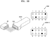
- FIGS. 3A and 3B are conceptual diagrams illustrating methods of respectively coupling charging terminal connectors 310 and 320 of wireless ultrasound probes 300A and 300B to a power supply terminal 30, according to embodiments.
- the charging terminal connector 310 of the wireless ultrasound probe 300A may be coupled to the power supply terminal 30 of an ultrasound imaging apparatus.
- the charging terminal connector 310 may include a plurality of pins.
- the charging terminal connector 310 may include the same number of pins as that of a plurality of openings in the power supply terminal 30.
- a diameter of each of the plurality of pins and a separation distance therebetween may respectively correspond to a diameter of and a separation distance between the plurality of openings in the power supply terminal 30.
- the charging terminal connector 310 may be pin mapped so that at least one of the plurality of pins included therein may receive power from the power supply terminal 30. In an embodiment, only at least one of the plurality of openings in the power supply terminal 30 may supply power to the at least one of the plurality of pins in the charging terminal connector 310.
- pin mapping may refer to mapping such that power is transmitted or received via a combination of at least one of the plurality of pins or openings or at least two of the plurality of pins or openings.
- the power supply terminal 30 and the charging terminal connector 310 may be respectively mapped according to preset pin maps 30M and 300M-1.
- the power supply terminal 30 may be mapped to supply a charging power to the wireless ultrasound probe 300A via fifth and seventh openings among the plurality of openings.
- the charging terminal connector 310 may also be mapped to receive a charging power from the power supply terminal 30 via fifth and seventh pins.
- the pin map 300M-1 of the charging terminal connector 310 of the wireless ultrasound probe 300A is identical to the pin map 30M of the power supply terminal 30, and accordingly, the wireless ultrasound probe 300A may receive a charging power from the power supply terminal 30.
- the charging terminal connector 320 of the wireless ultrasound probe 300B may be coupled to the power supply terminal 30.
- the charging terminal connector 320 may include a plurality of pins that are coupled to the power supply terminal 30.
- the charging terminal connector 320 may include the same number of pins as that of the plurality of openings formed in the power supply terminal 30.
- a diameter of and a separation distance between the plurality of pins included in the charging terminal connector 320 may respectively correspond to a diameter of and a separation distance between the plurality of openings in the power supply terminal 30.
- the charging terminal connector 320 may receive a charging power for charging a battery of the wireless ultrasound probe 300B via first and ninth pins among the plurality of pins.
- the power supply terminal 30 may be mapped to supply power for charging the wireless ultrasound probe 300B via the fifth and seventh openings among the plurality of openings.
- the pin map 30M of the power supply terminal 30 is not identical to the pin map 300M-2 of the charging terminal connector 320 of the wireless ultrasound probe 300B.
- the pin map 300M-2 of the charging terminal connector 320 of the wireless ultrasound probe 300B is not identical to the pin map 30M of the power supply terminal 30, a charging power is not supplied to the wireless ultrasound probe 300B even when the wireless ultrasound probe 300B is physically coupled to the power supply terminal 30. Furthermore, when the charging power is not supplied to the wireless ultrasound probe 300B, the ultrasound imaging apparatus is not paired wirelessly with the wireless ultrasound probe 300B even when the wireless ultrasound probe 300B is physically coupled to the power supply terminal 30.
- the wireless ultrasound probes 300A and 300B are respectively capable of being coupled to the power supply terminal 30, but whether the wireless ultrasound probes 300A and 300B are each to receive a charging power from the power supply terminal 30 is determined according to the pin maps 300M-1 and 300M-2. In other words, only the wireless ultrasound probe 300A that is mapped based on the same pin map as that of the power supply terminal 30 may receive a charging power from the power supply terminal 30.
- the wireless ultrasound probe 300B having the pin map 300M-2 that is not identical to the pin map 30M cannot be charged or paired wirelessly with the ultrasound imaging apparatus.
- this configuration may weaken or eliminate the inclination to steal.
- FIG. 4 is a block diagram of a configuration of a wireless ultrasound probe 400 according to an embodiment.
- the wireless ultrasound probe 400 may transmit ultrasound signals to an object and receive echo signals reflected from the object to thereby produce reception signals.
- the wireless ultrasound probe 400 may also perform image processing on the reception signals to thereby generate ultrasound image data.
- the wireless ultrasound probe 400 may transmit the generated ultrasound image data wirelessly to an ultrasound imaging apparatus.
- the wireless ultrasound probe 400 may include a charging terminal connector 410, a battery 420, a controller 430, and a wireless communication module 440.
- the charging terminal connector 410 may be coupled to a power supply terminal of the ultrasound imaging apparatus to receive power from the power supply terminal and charge the battery 420.
- the charging terminal connector 410 may have a unique shape enabling it to be physically coupled to the power supply terminal.
- the charging terminal connector 410 may have a shape corresponding to that of the power supply terminal of the ultrasound imaging apparatus, such that the charging terminal connector 410 is coupled only to the predetermined power supply terminal.
- the charging terminal connector 410 may include a plurality of pins that are coupled to the power supply terminal of the ultrasound imaging apparatus and may be pin mapped such that at least one of the plurality of pins included therein may receive power from the power supply terminal.
- the charging terminal connector 410 may be pin mapped to have a combination of at least two of the plurality of pins via which power is received from the power supply terminal, and pin mapping of the charging terminal connector 410 may be identical to pin mapping of the power supply terminal.
- the battery 420 may supply an operating power to the wireless ultrasound probe 400.
- the battery 420 may supply an operating power to the controller 430 and the wireless communication module 440.
- an operating power may mean a power generated by the battery 420 and supplied to perform respective functions of the controller 430 and the wireless communication module 440.
- the battery 420 may be a rechargeable secondary battery.
- the battery 420 may be a lithium ion (Li-ion) battery, but is not limited thereto.
- the battery 420 may consist of at least one of a Li-ion battery, a Li polymer battery, a nickel (Ni)-cadmium (Cd) battery, a lead-acid battery, and a nickel metal hydride battery (NiMH).
- the controller 430 may receive an operating power from the battery 420 to control the wireless communication module 440.
- the controller 430 may recognize a battery charging state in which the charging terminal connector 410 is physically coupled to the power supply terminal such that power is applied to the battery 420.
- the controller 430 may control the wireless communication module 440 to be paired wirelessly to the ultrasound imaging apparatus by using a wireless communication method.
- the controller 430 may be formed as a hardware module including at least one of a central processing unit (CPU), a microprocessor, a graphic processing unit (GPU), random-access memory (RAM), and read-only memory (ROM).
- the controller 430 may be implemented as an application processor (AP).
- the controller 430 may also be implemented as a hardware component such as a FPGA or an ASIC.
- the controller 430 may control the wireless communication module 440 to wirelessly transmit ID information and characteristic information to the ultrasound imaging apparatus.
- the ID information may refer to an ID and a type of the wireless ultrasound probe 400
- the characteristic information may be information including at least one of a wireless communication frequency used for wireless communication with the ultrasound imaging apparatus, a connection type, an executable application, a wireless communication method, a communication status, battery charging information, a remaining battery capacity, and a remaining usability time.
- the wireless communication module 440 may be paired with the ultrasound imaging apparatus by using a wireless communication method.
- the wireless communication module 440 may be paired wirelessly to the ultrasound imaging apparatus by using at least one of wireless communication methods including a Wireless Local Area Network (WLAN), Wireless Fidelity (Wi-Fi), Bluetooth, Zigbee, Wi-Fi Direct (WFD), Infrared Data Association (IrDA), Bluetooth Low Energy (BLE), Near Field Communication (NFC), Wireless Broadband Internet (WiBro), World Interoperability for Microwave Access (WiMAX), Shared Wireless Access Protocol (SWAP), Wireless Gigabit Alliance (WiGig), and radio frequency (RF) communication.
- WLAN Wireless Local Area Network
- Wi-Fi Wireless Fidelity
- Wi-Fi Direct WFD
- IrDA Infrared Data Association
- BLE Bluetooth Low Energy
- NFC Near Field Communication
- WiBro Wireless Broadband Internet
- SWAP Wireless Gigabit Alliance
- WiGig Wireless Gigabit Alliance
- RF radio frequency
- the wireless communication module 440 may include a 60-GHz millimeter wave (mmWave) data communication module configured to transmit ultrasound raw data to the ultrasound imaging apparatus.
- the wireless communication module 440 may include only a local area communication module for pairing with the ultrasound imaging apparatus.
- mmWave millimeter wave
- the wireless ultrasound probe 400 may further include a biometric recognition module.
- the biometric recognition module may acquire biometric information including at least one of a user's fingerprint, iris, and facial contour.
- the controller 430 may identify a user based on the biometric information acquired by the biometric recognition module and control the wireless communication module 440 to be paired with the ultrasound imaging apparatus by using a wireless communication method according to the identified user, as will be described in more detail below with reference to FIG. 7C .
- FIG. 5 is a block diagram of a configuration of an ultrasound imaging apparatus 500 according to an embodiment.
- the ultrasound imaging apparatus 500 may be connected wirelessly with a wireless ultrasound probe 400.
- the ultrasound imaging apparatus 500 may be implemented as a cart type apparatus as well as a portable type apparatus. Examples of portable ultrasound imaging apparatuses may include, but are not limited to, a PACS viewer, a HCU device, a smartphone, a laptop computer, a PDA, and a tablet PC.
- the ultrasound imaging apparatus 500 may be an apparatus configured to generate an ultrasound image by processing ultrasound image data received from the wireless ultrasound probes 400 and display the generated image, or may be an apparatus for implementing only an image display function without performing a separate image processing function.
- the ultrasound imaging apparatus 500 may include a power supply terminal 510, a sensor 512, a controller 520, a wireless communication module 530, and a display 540.
- the power supply terminal 510 may supply power to the wireless ultrasound probe 400 to charge the battery (420 of FIG. 4 ) of the wireless ultrasound probe 400.
- the power supply terminal 510 may be physically coupled with the charging terminal connector (410 of FIG. 4 ) of the wireless ultrasound probe 400.
- the power supply terminal 510 may have a unique shape enabling it to be coupled only to the wireless ultrasound probe 400 including the charging terminal connector 410 having a predetermined shape.
- the power supply terminal 510 may include a plurality of pins and may be pin mapped such that at least one of the plurality of pins may supply a charging power to the wireless ultrasound probe 400 via the charging terminal connector 410.
- the power supply terminal 510 may include a plurality of openings and may be pin mapped such that only at least one of the plurality of openings may supply a charging power to the wireless ultrasound probe 400 via the charging terminal connector 410. Pin mapping of the power supply terminal 510 may be identical to pin mapping of the charging terminal connector 410 of the wireless ultrasound probe 400.
- the sensor 512 may recognize a charging state in which the power supply terminal 510 is physically coupled with the charging terminal connector 410 to supply power to the battery 420. In an embodiment, the sensor 512 may recognize whether the pin mapping of the power supply terminal 510 is identical to the pin mapping of the charging terminal connector 410.
- the sensor 512 may not only recognize a status of power connection between the power supply terminal 510 and the charging terminal connector 410 of the wireless ultrasound probe 400 but also acquire additional information. For example, even when the power supply terminal 510 of the ultrasound imaging apparatus 500 has the same physical shape as the charging terminal connector 410 of the wireless ultrasound probe 400, the power supply terminal 510 may supply a positive (+) power via three (3) terminals (e.g., terminals 1 through 3), but the charging terminal connector 410 may receive the positive (+) power via two (2) terminals (e.g., terminals 2 and 3).
- a charging power may be supplied to the wireless ultrasound probe 400, but the ultrasound imaging apparatus 500 is not capable of being paired with the wireless ultrasound probe 400 due to a mismatch between power terminals in the power supply terminal 510 and the charging terminal connector 410.
- the sensor 512 may acquire information about the number and positions of 'positive' (+) terminals via which a charging power is to be supplied.
- the controller 520 may receive from the sensor 512 a state of physical mating between the power supply terminal 510 and the charging terminal connector 410 of the wireless ultrasound probe 400 and a charging state of the wireless ultrasound probe 400, and control the wireless communication module 530 such that the wireless ultrasound probe 400 in the charging state may be paired with the ultrasound imaging apparatus 500 by using a wireless communication method.
- the controller 520 may determine whether to supply a charging power to the wireless ultrasound probe 400, based on a result of sensing by the sensor 512 as to whether pin mapping of the power supply terminal 510 is identical to pin mapping of the charging terminal connector 410.
- the controller 520 may control the power supply terminal 510 to supply a charging power to the wireless ultrasound probe 400 only when the pin mapping of the power supply terminal 510 is identical to the pin mapping of the charging terminal connector 410.
- the controller 520 may prevent the power supply terminal 510 from supplying power to the wireless ultrasound probe 400.
- the controller 520 may be formed as a hardware module including at least one of a CPU, a microprocessor, a GPU, RAM, and ROM.
- the controller 520 when the ultrasound imaging apparatus 500 is implemented as a portable type apparatus such as a smartphone, a laptop computer, a PDA, or a tablet PC, the controller 520 the controller 520 may be implemented as an AP.
- the controller 520 may control the wireless communication module 530 to receive ID information and characteristic information of the wireless ultrasound probe 400 that is coupled to the power supply terminal 510, and determine whether to pair with the wireless ultrasound probe 400 based on the ID information and the characteristic information of the wireless ultrasound probe 400.
- the characteristic information of the wireless ultrasound probe 400 may include at least one of a wireless communication frequency used for communication, a connection type, an executable application, a wireless communication method, a communication status, battery charging information, a remaining battery capacity, and a remaining usability time.
- the controller 520 may respectively compare the received ID information and characteristic information with prestored ID information and characteristic information and control the wireless communication module 530 to pair only with the wireless ultrasound probe 400 registered with the ultrasound imaging apparatus 500.
- the wireless communication module 530 may be connected with the wireless ultrasound probe 400 by using a wireless communication method.
- the wireless communication module 530 may be paired wirelessly with the wireless ultrasound probe 400 by using at least one of wireless communication methods including a WLAN, Wi-Fi, Bluetooth, Zigbee, WFD, IrDA, BLE, NFC, WiBro, WiMAX, SWAP, WiGig, and RF communication.
- the display 540 may display a UI indicating a state in which the wireless ultrasound probe 400 is being charged and a state of pairing with the wireless ultrasound probe 400.
- the display 540 may display a UI indicating a state in which power is prevented from being supplied to the wireless ultrasound probe 400.
- the display 540 may be constructed by a physical device including at least one of a liquid crystal display (LCD), a plasma display panel (PDP), an organic light-emitting diode (OLED) display, a field-emission display (FED), a an LED display, a vacuum fluorescent display (VFD), a digital light processing (DLP) display, a flat panel display, a three-dimensional (3D) display, and a transparent display, but embodiments are not limited thereto.
- the display 540 may be formed as a touch screen including a touch interface.
- the ultrasound imaging apparatus 500 may further include a user input interface for receiving a password or a specific pattern from a user.
- the user input interface may include hardware components such as a key pad, a mouse, a trackball, a touch pad, a touch screen, and a jog switch, but are not limited thereto.
- the display 540 When the display 540 is formed as a touch screen, the display 540 may be integrated with a touch pad to receive a user touch input.
- the controller 520 may determine whether to pair the ultrasound imaging apparatus 500 with the wireless ultrasound probe 400, based on the password or specific pattern received via the user input interface, as will be described in more detail below with reference to FIGS. 7A and 7B .
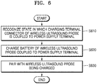
- FIG. 6 is a flowchart of a method, performed by an ultrasound imaging apparatus, of pairing with a wireless ultrasound probe, according to an embodiment.
- the ultrasound imaging apparatus recognizes a state in which a charging terminal connector of the wireless ultrasound probe is coupled to a power supply terminal (S610).
- the power supply terminal of the ultrasound imaging apparatus may have a unique shape enabling it to be coupled only to the wireless ultrasound probe including the charging terminal connector with a predetermined shape.
- the ultrasound imaging apparatus may recognize whether pin mapping of the power supply terminal is identical to pin mapping of the charging terminal connector of the wireless ultrasound probe.
- the ultrasound imaging apparatus charges a battery of the wireless ultrasound probe coupled to the power supply terminal (S620).
- the ultrasound imaging apparatus may supply a charging power to the wireless ultrasound probe only when pin mapping of the power supply terminal is identical to pin mapping of the charging terminal connector of the wireless ultrasound probe.
- the ultrasound imaging apparatus may prevent power from being supplied to the wireless ultrasound probe.
- the ultrasound imaging apparatus pairs with the wireless ultrasound probe being charged by using a wireless communication method (S630).
- the ultrasound imaging apparatus may transmit a pairing signal to the wireless ultrasound probe that is coupled to the power supply terminal and is receiving a charging power via the power supply terminal and wirelessly connect with the wireless ultrasound probe.
- the ultrasound imaging apparatus may be paired with the wireless ultrasound probe by using at least one of wireless communication methods including a WLAN, Wi-Fi, Bluetooth, Zigbee, WFD, IrDA, BLE, NFC, WiBro, WiMAX, SWAP, WiGig, and RF communication.
- FIGS. 7A and 7B are diagrams for explaining methods, performed by an ultrasound imaging apparatus 700, of pairing with a wireless ultrasound probe by receiving a password from a user, according to embodiments.
- the ultrasound imaging apparatus 700 may receive a user input of entering a password.
- a display 740 of the ultrasound imaging apparatus 700 may display in a first region 741 a thumbnail image 711 of a wireless ultrasound probe to which a charging power is being supplied via a power supply terminal.
- the ultrasound imaging apparatus 700 may display a password UI 750 requesting a user to enter a password on the display 740.
- the password is a preset security code that allows the user to use the wireless ultrasound probe that is coupled to the ultrasound imaging apparatus 700 and is being charged and may be composed of letters, numerals, or any combination thereof.
- the ultrasound imaging apparatus 700 may receive a password from the user via a user input device including at least one of a key pad, a mouse, a trackball, a touch pad, a touch screen, and a jog switch.
- the display 740 When the display 740 is formed as a touch screen, the display 740 may be integrated with a touch pad to display a keypad UI including letters and numerals and receive a user touch input for entering a password via the keypad UI.
- the ultrasound imaging apparatus 700 may be paired wirelessly with a wireless ultrasound probe only when a password received from the user matches a security code predetermined with respect to the wireless ultrasound probe. Furthermore, the ultrasound imaging apparatus 700 may use the wireless ultrasound probe paired wirelessly thereto to transmit ultrasound signals to an object and receive ultrasound echo signals reflected from the object to thereby acquire ultrasound image data with respect to the object. When the password received from the user does not match the security code predetermined with respect to the wireless ultrasound probe, the ultrasound imaging apparatus 700 may prevent a charging power from being supplied to the wireless ultrasound probe.
- an ultrasound imaging apparatus 700 may display in a first region 741 of a display 740 a thumbnail image 711 of a wireless ultrasound probe to which a charging power is being supplied via a power supply terminal.
- the ultrasound imaging apparatus 700 may receive a user input of entering a specific pattern on the display 740.
- the ultrasound imaging apparatus 700 may display a pattern UI 760 requesting a user to enter a specific pattern on the display 740.
- the display 740 may be formed as a touch screen, and receive a user input of touching specific positions on the pattern UI 760 and sequentially dragging over the specific positions.
- the ultrasound imaging apparatus 700 may be paired wirelessly with a wireless ultrasound probe only when a specific pattern received from the user matches a pattern preset with respect to the wireless ultrasound probe. Furthermore, the ultrasound imaging apparatus 700 may use the wireless ultrasound probe paired wirelessly thereto to transmit ultrasound signals to an object and receive ultrasound echo signals reflected from the object to thereby acquire ultrasound image data with respect to the object.
- the ultrasound imaging apparatus 700 may prevent a charging power from being supplied to the wireless ultrasound probe.
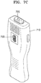
- FIG. 7C is a perspective view of a wireless ultrasound probe 710 according to an embodiment.
- the wireless ultrasound probe 710 may include a charging terminal connector 720 and a fingerprint information acquisitor 730 that are respectively provided on sides of the wireless ultrasound probe 710. Since the charging terminal connector 720 corresponds to the charging terminal connectors (210 of FIG. 2A and 220 of FIG. 2B ) described with reference to FIGS. 2A and 2B , a detailed description thereof will be omitted here.
- the fingerprint information acquisitor 730 may recognize a fingerprint possessed by a user of the wireless ultrasound probe 710 and transmit information about the recognized fingerprint to a controller of the wireless ultrasound probe 710.
- the wireless ultrasound probe 710 may be paired wirelessly to the ultrasound imaging apparatus (700 of FIGS. 7A or 7B ).
- the wireless ultrasound probe 710 may be unlocked to transmit ultrasound signals to an object and receive ultrasound echo signals reflected from the object.
- the wireless ultrasound probe 710 switches back to a locked state such that all operations thereof are stopped.
- FIG. 7C shows that the wireless ultrasound probe 710 includes the fingerprint information acquisitor 730, embodiments are not limited thereto.
- the wireless ultrasound probe 710 may include a biometric recognition module for recognizing a user's iris or facial contour.
- FIG. 8 is a flowchart of a method, performed by an ultrasound imaging apparatus, of determining whether to pair with a wireless ultrasound probe and displaying a state of pairing with the wireless ultrasound probe; according to an embodiment.
- the ultrasound imaging apparatus recognizes a state in which a charging terminal connector of the wireless ultrasound probe is coupled to a power supply terminal (S810).
- the power supply terminal of the ultrasound imaging apparatus may have a unique shape enabling it to be coupled only to the wireless ultrasound probe including the charging terminal connector having a predetermined shape.
- the ultrasound imaging apparatus may recognize whether pin mapping of the power supply terminal is identical to pin mapping of the charging terminal connector of the wireless ultrasound probe.
- the ultrasound imaging apparatus checks whether pin mapping of the power supply terminal is identical to pin mapping of the charging terminal connector (S820). Even when the charging terminal connector of the wireless ultrasound probe is physically coupled to the power supply terminal of the ultrasound imaging apparatus in operation S810, the pin mapping of the power supply terminal may be different from that of the charging terminal connector. In an embodiment, pin mapping of the charging terminal connector of the wireless ultrasound probe may be set to receive a charging power only via the specific power supply terminal of the ultrasound imaging apparatus.
- the ultrasound imaging apparatus may supply a charging power to the wireless ultrasound probe. Otherwise, when the pin mapping of the power supply terminal of the ultrasound imaging apparatus does not match the pin mapping of the charging terminal connector of the wireless ultrasound probe in operation S820, the ultrasound imaging apparatus may prevent a charging power from being supplied to the wireless ultrasound probe.
- the ultrasound imaging apparatus determines whether the wireless ultrasound probe is unlocked (S830).
- "unlocked” may mean that the wireless ultrasound probe is paired with the ultrasound imaging apparatus by using a wireless communication method even when a charging power is supplied to the wireless ultrasound probe and authorization is granted to use the wireless ultrasound probe to acquire ultrasound image data with respect to the object.
- Matching of the pin mappings with each other in operation S820 is a primary unlock operation for using the wireless ultrasound probe.
- Operation S830 may be a secondary unlock operation for pairing with the wireless ultrasound probe being charged and acquiring ultrasound image data.
- the ultrasound imaging apparatus may receive a password or specific pattern with respect to the wireless ultrasound probe from the user and determine whether to pair with the wireless ultrasound probe being charged based on the received password or specific pattern.
- the ultrasound imaging apparatus may wirelessly pair with the wireless ultrasound probe only when the password received from the user matches a security code predetermined with respect to the wireless ultrasound probe (S840).
- the ultrasound imaging apparatus may receive ID information and characteristic information of the wireless ultrasound probe being charged and determine whether to pair with the wireless ultrasound probe based on the received ID information and the characteristic information of the wireless ultrasound probe.
- the ID information may refer to an ID and a type of the wireless ultrasound probe
- the characteristic information may be information including at least one of a wireless communication frequency used for wireless communication with the ultrasound imaging apparatus, a connection type, an executable application, a wireless communication method, a communication status, battery charging information, a remaining battery capacity, and a remaining usability time.
- the ultrasound imaging apparatus may wirelessly pair with the wireless ultrasound probe only when the received ID information and characteristic information of the wireless ultrasound probe respectively match ID information and characteristic information predetermined by the ultrasound imaging apparatus to enable pairing (S840).
- the ultrasound imaging apparatus may acquire biometric information including at least one of a fingerprint, an iris, and a facial contour of a user of the wireless ultrasound probe and identify the user based on the acquired biometric information.
- the ultrasound imaging apparatus may determine whether to pair with the wireless ultrasound probe according to the biometric information of the identified user.
- the wireless ultrasound probe may include a biometric recognition module configured to acquire biometric information including at least one of a user's fingerprint, iris, and facial contour.
- the wireless ultrasound probe may determine to wirelessly pair with the ultrasound imaging apparatus only when biometric information acquired by the biometric recognition module matches biometric information predetermined to authorize the use of the wireless ultrasound probe (S840).
- the ultrasound imaging apparatus pairs with the wireless ultrasound probe (S840).
- the ultrasound imaging apparatus may transmit a pairing signal to the wireless ultrasound probe unlocked in operation S830 and wirelessly connect with the wireless ultrasound probe.
- the ultrasound imaging apparatus may be paired with the wireless ultrasound probe by using at least one of wireless communication methods including a WLAN, Wi-Fi, Bluetooth, Zigbee, WFD, IrDA, BLE, NFC, WiBro, WiMAX, SWAP, WiGig, and RF communication.
- the ultrasound imaging apparatus displays a UI indicating a charging state of the wireless ultrasound probe and a state of pairing with the wireless ultrasound probe (S850), as will be described in more detail below with reference to FIG. 9A .
- the ultrasound imaging apparatus prevents a charging power from being supplied to the wireless ultrasound probe (S860).
- the ultrasound imaging apparatus may prevent power from being supplied to the wireless ultrasound probe when the pin mapping of the power supply terminal does not match the pin mapping of the charging terminal connector of the wireless ultrasound probe in operation S820 or when it is not determined in operation S830 that the wireless ultrasound probe is unlocked.
- the ultrasound imaging apparatus determines not to pair with the wireless ultrasound probe (S870).
- the wireless ultrasound probe cannot apply an ultrasound signal to the object or receive an ultrasound echo signal reflected from the object. Thus, it becomes impossible to use the wireless ultrasound probe.
- the ultrasound imaging apparatus displays a UI indicating a state in which supply of a charging power is prevented (S880).
- the ultrasound imaging apparatus may display on a display a UI indicating a state in which supply of a charging power is prevented and that pairing with the wireless ultrasound probe is impossible, as will be described in more detail below with reference to FIG. 9B .
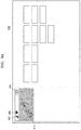
- FIGS. 9A and 9B are diagrams for explaining methods by which an ultrasound imaging apparatus displays states of pairing with wireless ultrasound probes, according to embodiments.
- a display 900 of the ultrasound imaging apparatus may display a thumbnail image 910 of a wireless ultrasound probe that is paired thereto by using a wireless communication method and UIs related to wireless pairing, a communication status, a communication method, battery charging, etc.
- the display 900 may be attached to a control panel to display a UI, but embodiments are not limited thereto.
- the display 900 may also display an ultrasound image of an object generated based on ultrasound image data produced by the wireless ultrasound probe.
- the display 900 may display UIs used for operating the ultrasound imaging apparatus, e.g., for obtaining an ultrasound image of the object or manipulating the obtained ultrasound image by using the ultrasound imaging apparatus.
- a region in which the thumbnail image 910 of the wireless ultrasound probe is displayed may be shown in a certain color of shade to distinguish the region from the remaining regions. This may indicate that the wireless ultrasound probe is paired with the ultrasound imaging apparatus.
- An UI indicating status information of the wireless ultrasound probe may be displayed at the top of the region in which the thumbnail image 910 of the wireless ultrasound probe is displayed.
- the UI may be a GUI graphically representing the status information.
- the UI displayed on the display 900 may include a first UI 920 indicating a status of wireless connection between the wireless ultrasound probe and the ultrasound imaging apparatus, a second UI 930 indicating a wireless communication method used to pair the wireless ultrasound probe with the ultrasound imaging apparatus, and a third UI 940 indicating a state in which a charging power is being supplied to the wireless ultrasound probe.
- the display 900 may display ID information of the wireless ultrasound probe paired wirelessly to the ultrasound imaging apparatus.
- the wireless ultrasound probe paired with the ultrasound imaging apparatus may be L3-12W.
- the first UI 920 may be a UI indicating a wireless connection status as the number of bar-shaped antennas. The more bars in the first UI 92 may mean the smoother wireless connection.
- the second UI 930 may be a UI composed of symbols indicating Wi-fi, Bluetooth, NFC, WiGig, etc. and may represent a wireless communication method used to pair the wireless ultrasound probe with the ultrasound imaging apparatus.
- the number of bars in the first UI 920 and the number of antennas in the second UI 930 may be UIs that graphically represent a status of wireless communication between the wireless ultrasound probe and the ultrasound imaging apparatus. For example, in the second UI 930 indicating pairing via Wi-fi, the more antennas that are filled in a fan-shaped antenna symbol may mean the smoother Wi-fi pairing between the wireless ultrasound probe and the ultrasound imaging apparatus.
- the third UI 940 may be a UI indicating that the wireless ultrasound probe receives a charging power from a power supply terminal of the ultrasound imaging apparatus and is charging a battery embedded therein.
- the first through third UIs 920, 930, and 940 displayed on the display 900 may allow the user to easily identify status information of the wireless ultrasound probe paired with the ultrasound imaging apparatus, thereby increasing user convenience.
- the display 900 of the ultrasound imaging apparatus displays a thumbnail image 911 of a wireless ultrasound probe
- the wireless ultrasound probe represented by the thumbnail image 911 may be a wireless ultrasound probe that is not paired with the ultrasound imaging apparatus.
- a region in which the thumbnail image 911 of the wireless ultrasound probe is displayed is not shown in a certain color or shade, which means that the wireless ultrasound probe is not paired with the ultrasound imaging apparatus.
- pin mapping of the power supply terminal may not match pin mapping of the charging terminal connector (S820 of FIG. 8 ), or the wireless ultrasound probe may not be unlocked (S830 of FIG. 8 ). In this case, a charging power may be prevented from being supplied to the wireless ultrasound probe, and the wireless ultrasound probe may not be paired with the ultrasound imaging apparatus.
- a first UI 921 displayed on the display 900 maybe a UI indicating a state in which the wireless ultrasound probe is not connected wirelessly to the ultrasound imaging apparatus.
- Signal bars displayed in the first UI 921 are empty, which means wireless connection is not made between the wireless ultrasound probe and the ultrasound imaging apparatus.
- a second UI 931 indicates a wireless communication method used to pair the wireless ultrasound probe with the ultrasound imaging apparatus. However, since the wireless ultrasound probe is currently not being paired with the ultrasound imaging apparatus, fan-shaped signal bars displayed in the second UI 931 are all empty.
- a third UI 941 may be a UI indicating a state in which a charging power is not being supplied to the wireless ultrasound probe.
- the third UI 941 indicates that supply of power from the ultrasound imaging apparatus to the wireless ultrasound probe is prevented. In other words, even though the wireless ultrasound probe is physically coupled to the ultrasound imaging apparatus, an electrical connection is not actually made therebetween, and thus, power supply and charging cannot be performed and thus pairing is terminated. To restore pairing with the wireless ultrasound probe, the wireless ultrasound probe has to be electrically connected to the ultrasound imaging apparatus and receive a charging power therefrom.
- the display 900 of the ultrasound imaging apparatus displays UIs indicating a state in which the wireless ultrasound probe is not paired wirelessly to the ultrasound imaging apparatus and is not being charged. This may allow the user to quickly identify a status of the wireless ultrasound probe, thereby increasing user convenience.
- FIG. 10 is a block diagram of a configuration of an ultrasound system 1000 including a wireless ultrasound probe 1100 and an ultrasound imaging apparatus 1200, according to an embodiment.
- the ultrasound system 1000 may include the wireless ultrasound probe 1100 and the ultrasound imaging apparatus 1200.
- the wireless ultrasound probe 1100 may include a transmitter 1130, a transducer 1150, a receiver 1170, a controller 1180, and a communicator 1190.
- FIG. 10 shows that the wireless ultrasound probe 1100 includes both the transmitter 1130 and the receiver 1170, according to an implemented configuration, the wireless ultrasound probe 1100 may include some of the components of the transmitter 1130 and the receiver 1170 while the ultrasound diagnosis apparatus 1200 may also include some of them.
- the transducer 1150 may include a plurality of transducer elements.
- the plurality of transducer elements transmit ultrasound signals to an object 1 in response to transmitting signals received from the transmitter 1130.
- the transducer elements may receive ultrasound signals reflected from the object 1 to generate reception signals.
- the controller 1180 controls the transmitter 1130 to generate transmitting signals to be respectively applied to the transducer elements based on a position and a focal point of the transducer elements.
- the controller 1180 controls the receiver 1170 to generate ultrasound data by performing analog-to-digital conversion on the reception signals received from the transducer 1150 and summing the analog-to-digital converted reception signals based on a position and a focal point of the transducer elements.
- the communicator 1190 may wirelessly transmit the generated ultrasound data or ultrasound image to the ultrasound diagnosis apparatus 1200 via a wireless network.
- the communicator 240 may receive a control signal and data from the ultrasound diagnosis apparatus 1200.
- the ultrasound system 1000 may also include at least one wireless ultrasound probe 1100 according to the implementation form.
- the ultrasound diagnosis apparatus 1200 may receive ultrasound data or an ultrasound image from the wireless ultrasound probe 1100.
- the ultrasound diagnosis apparatus 1200 may include a controller 1220, an image processor 1230, a display 1240, a storage 1250, a communicator 1260, and an input interface 1270.
- the image processor 1230 may generate an ultrasound image by using ultrasound data received from the wireless ultrasound probe 1100.
- the display 1240 may display an ultrasound image received from the wireless ultrasound probe 1100 and an ultrasound image generated by the ultrasound diagnosis apparatus 1200 and the ultrasound diagnosis system 1000.
- the ultrasound diagnosis system 1000 may include two or more displays 1240 according to its implemented configuration. Furthermore, the display 1240 may be combined with a touch panel to form a touch screen.
- the controller 1220 may control all operations of the ultrasound diagnosis system 1000 and flow of signals between the internal elements of the ultrasound diagnosis system 1000.
- the controller 1220 may include a memory for storing a program or data to perform functions of the ultrasound diagnosis system 1000 and a processor for processing the program or data. Furthermore, the controller 1220 may control the operation of the ultrasound diagnosis system 1000 by receiving a control signal from the input interface 1270 or an external apparatus.
- the ultrasound diagnosis apparatus 1200 may include the communicator 1260 and may be connected to external apparatuses, for example, servers, medical apparatuses, and portable devices such as smart phones, tablet PCs, wearable devices, etc., via the communicator 1260.
- external apparatuses for example, servers, medical apparatuses, and portable devices such as smart phones, tablet PCs, wearable devices, etc.
- the communicator 1260 may include at least one element capable of communicating with the external apparatuses.
- the communicator 1260 may include at least one of a local area communication module, a wired communication module, and a wireless communication module.
- the communicator 1260 may receive a control signal and data from an external apparatus and transmit the received control signal to the controller 1220 such that the controller 1220 may control the ultrasound diagnosis system 1000 in response to the received control signal.
- the external apparatus may process data from the external apparatus in response to the control signal from the controller 1220 received via the communicator 1260.
- a program for controlling the ultrasound diagnosis system 1000 may be installed in the external apparatus.
- the program may include command languages for performing part of operation of the controller 1220 or the entire operation thereof.
- the program may be pre-installed in the external apparatus or may be installed by a user of the external apparatus by downloading the program from a server that provides applications.
- the server that provides applications may include a recording medium on which the program is stored.
- the storage 1250 may store various data or programs for driving and controlling the ultrasound diagnosis system 1000, input and/or output ultrasound data, ultrasound images, etc.
- the input interface 1270 receives a user input for controlling the ultrasound diagnosis system 1000.
- the user input may include an input for manipulating a button, a keypad, a mouse, a trackball, a jog switch, or a knop, an input for touching a touchpad or a touch screen, a voice input, a motion input, and an input of biometric information such as iris recognition or fingerprint recognition, but embodiments are not limited thereto.
- Examples of the ultrasound diagnosis apparatus 1200 according to an embodiment will now be described in detail with reference to FIGS. 11A through 11C .
- FIGS. 11A, 11B, and 11C are diagrams illustrating ultrasound diagnosis apparatus according to an exemplary embodiment.
- the ultrasound diagnosis apparatuses 1000a and 1000b may include a main display 1310 and a sub-display 1320. At least one among the main display 1310 and the sub-display 1320 may include a touch screen.
- the main display 1310 and the sub-display 1320 may display ultrasound images and/or various information processed by the ultrasound diagnosis apparatuses 1000a and 1000b.
- the main display 1310 and the sub-display 1320 may provide graphical user interfaces (GUI), thereby receiving user's inputs of data to control the ultrasound diagnosis apparatuses 1000a and 1000b.
- GUI graphical user interfaces
- the main display 1310 may display an ultrasound image
- the sub-display 1320 may display a control panel to control display of the ultrasound image as a GUI.
- the sub-display 1320 may receive an input of data to control the display of an image through the control panel displayed as a GUI.
- the ultrasound diagnosis apparatuses 1000a and 1000b may control the display of the ultrasound image on the main display 1310 by using the input control data.
- the ultrasound diagnosis apparatus 1000b may include a control panel 1340.
- the control panel 1340 may include buttons, trackballs, jog switches, or knobs, and may receive data to control the ultrasound diagnosis apparatus 1000b from the user.
- the control panel 1340 may include a time gain compensation (TGC) button 1331 and a freeze button 1332.
- TGC time gain compensation
- the TGC button 1331 is to set a TGC value for each depth of an ultrasound image.
- the ultrasound diagnosis apparatus 1000b may keep displaying a frame image at that time point.
- buttons, trackballs, jog switches, and knobs included in the control panel 1340 may be provided as a GUI to the main display 1310 or the sub-display 1320.
- the ultrasound diagnosis apparatus 1000c may include a portable device.
- An example of the portable ultrasound diagnosis apparatus 1000c may include, for example, smart phones including probes and applications, laptop computers, personal digital assistants (PDAs), or tablet PCs, but an exemplary embodiment is not limited thereto.
- the ultrasound diagnosis apparatus 1000c may include the probe 2000 and a main body 1400.
- the probe 2000 may be connected to one side of the main body 1400 by wire or wirelessly.
- the main body 1400 may include a touch screen 1450.
- the touch screen 1450 may display an ultrasound image, various pieces of information processed by the ultrasound diagnosis apparatus 1000c, and a GUI.
- the embodiments of the present disclosure can be written as computer programs and can be implemented in general-use digital computers that execute the programs using a computer-readable recording medium.
- the command language may be stored in the form of a program code, and when executed by a processor, the command language may generate a certain program module and perform certain operations.
- the command language may, when executed by a processor, may perform certain operations described in the embodiments disclosed in the present disclosure.
- Examples of the computer-readable recording medium include magnetic storage media (e.g., ROM, floppy disks, hard disks, etc.), optical recording media (e.g., CD-ROMs or DVDs), etc.
- magnetic storage media e.g., ROM, floppy disks, hard disks, etc.
- optical recording media e.g., CD-ROMs or DVDs
Landscapes
- Health & Medical Sciences (AREA)
- Life Sciences & Earth Sciences (AREA)
- Engineering & Computer Science (AREA)
- Physics & Mathematics (AREA)
- General Health & Medical Sciences (AREA)
- Molecular Biology (AREA)
- Public Health (AREA)
- Pathology (AREA)
- Radiology & Medical Imaging (AREA)
- Biomedical Technology (AREA)
- Heart & Thoracic Surgery (AREA)
- Medical Informatics (AREA)
- Biophysics (AREA)
- Surgery (AREA)
- Animal Behavior & Ethology (AREA)
- Veterinary Medicine (AREA)
- Nuclear Medicine, Radiotherapy & Molecular Imaging (AREA)
- Computer Networks & Wireless Communication (AREA)
- Human Computer Interaction (AREA)
- General Physics & Mathematics (AREA)
- Multimedia (AREA)
- Theoretical Computer Science (AREA)
- Power Engineering (AREA)
- Ophthalmology & Optometry (AREA)
- Oral & Maxillofacial Surgery (AREA)
- Ultra Sonic Daignosis Equipment (AREA)
Applications Claiming Priority (1)
| Application Number | Priority Date | Filing Date | Title |
|---|---|---|---|
| KR1020180015807A KR102608821B1 (ko) | 2018-02-08 | 2018-02-08 | 무선 초음파 프로브 및 무선 초음파 프로브와 연결되는 초음파 영상 장치 |
Publications (2)
| Publication Number | Publication Date |
|---|---|
| EP3524162A1 true EP3524162A1 (de) | 2019-08-14 |
| EP3524162B1 EP3524162B1 (de) | 2022-12-14 |
Family
ID=65236899
Family Applications (1)
| Application Number | Title | Priority Date | Filing Date |
|---|---|---|---|
| EP19153782.8A Active EP3524162B1 (de) | 2018-02-08 | 2019-01-25 | Drahtlose ultraschallsonde und an die drahtlose ultraschallsonde angeschlossene ultraschallbildgebungsvorrichtung |
Country Status (3)
| Country | Link |
|---|---|
| US (1) | US11627939B2 (de) |
| EP (1) | EP3524162B1 (de) |
| KR (1) | KR102608821B1 (de) |
Families Citing this family (5)
| Publication number | Priority date | Publication date | Assignee | Title |
|---|---|---|---|---|
| US12514550B2 (en) * | 2019-04-18 | 2026-01-06 | Densonics Imaging Inc. | Method and apparatus for wireless portable ultrasound imaging |
| CN114052776A (zh) * | 2020-07-29 | 2022-02-18 | 深圳迈瑞生物医疗电子股份有限公司 | 用于便携超声设备的台车、电池包和超声无线供电系统 |
| US20240153334A1 (en) * | 2021-03-05 | 2024-05-09 | Globelet Corporation | Methods, systems, and devices for reuse products, for reusing products, and product reuse promotion |
| US12082974B2 (en) | 2022-06-01 | 2024-09-10 | Fujifilm Sonosite, Inc. | Ultrasound scanner that supports handset wireless network connectivity |
| JP2024139198A (ja) * | 2023-03-27 | 2024-10-09 | 富士フイルム株式会社 | 超音波診断システムおよび超音波診断システムの制御方法 |
Citations (7)
| Publication number | Priority date | Publication date | Assignee | Title |
|---|---|---|---|---|
| US20030078501A1 (en) * | 1996-06-28 | 2003-04-24 | Sonosite, Inc. | Balance body ultrasound system |
| US20080194964A1 (en) * | 2007-02-08 | 2008-08-14 | Randall Kevin S | Ultrasound imaging systems |
| US20140180110A1 (en) * | 2012-12-20 | 2014-06-26 | General Electric Company | System and Method for Wireless Ultrasound Probe Pairing |
| US20160199028A1 (en) * | 2015-01-13 | 2016-07-14 | Samsung Medison Co., Ltd. | Wireless ultrasonic probe and ultrasonic apparatus having the same |
| WO2017009735A1 (en) * | 2015-07-16 | 2017-01-19 | Koninklijke Philips N.V. | Wireless ultrasound probe pairing with a mobile ultrasound system |
| EP3175794A1 (de) * | 2015-12-01 | 2017-06-07 | Samsung Medison Co., Ltd. | Ultraschalldiagnosevorrichtung, halteranordnung und verfahren zur steuerung der ultraschalldiagnosevorrichtung |
| US20170179774A1 (en) * | 2015-12-16 | 2017-06-22 | Samsung Medison Co., Ltd. | Ultrasound probe and charging method thereof |
Family Cites Families (35)
| Publication number | Priority date | Publication date | Assignee | Title |
|---|---|---|---|---|
| JPH0282314U (de) * | 1988-12-16 | 1990-06-26 | ||
| US6254540B1 (en) * | 1999-11-19 | 2001-07-03 | Olympus Optical Co., Ltd. | Ultrasonic image processing apparatus for constructing three-dimensional image using volume-rendering data and surface-rendering data simultaneously |
| JP2003010177A (ja) | 2001-06-22 | 2003-01-14 | Ge Medical Systems Global Technology Co Llc | 超音波プローブおよび超音波診断装置 |
| JP2004113629A (ja) * | 2002-09-27 | 2004-04-15 | Olympus Corp | 超音波診断装置 |
| JP2004141328A (ja) | 2002-10-23 | 2004-05-20 | Aloka Co Ltd | 超音波診断装置 |
| EP1690497B1 (de) * | 2003-12-02 | 2017-02-22 | Olympus Corporation | Ultraschallgerät |
| US8360979B2 (en) * | 2004-09-08 | 2013-01-29 | Jing Jiang Wen | Apparatus and method for ultrasonic color imaging |
| US20060112033A1 (en) * | 2004-10-12 | 2006-05-25 | Michael Vion | Ultrasound user interface learning system |
| EP1855596B1 (de) * | 2005-02-23 | 2015-07-01 | Koninklijke Philips N.V. | Diagnostisches ultraschallsystem zum nachweis von leberläsionen |
| TW200632716A (en) * | 2005-03-11 | 2006-09-16 | Hi Touch Imaging Tech Co Ltd | Method of displaying an ultrasonic image |
| US7764818B2 (en) * | 2005-06-20 | 2010-07-27 | Siemens Medical Solutions Usa, Inc. | Surface parameter adaptive ultrasound image processing |
| JP2008061938A (ja) | 2006-09-11 | 2008-03-21 | Toshiba Corp | 超音波プローブ、超音波診断装置及び超音波プローブ監視システム |
| US20100056924A1 (en) * | 2006-11-20 | 2010-03-04 | Koninklijke Philips Electronics N.V. | Control and display of ultrasonic microbubble cavitation |
| US20080148393A1 (en) * | 2006-12-15 | 2008-06-19 | Barry Myron Wendt | Neural authenticator and method |
| US20080194961A1 (en) * | 2007-02-08 | 2008-08-14 | Randall Kevin S | Probes for ultrasound imaging systems |
| US20080194963A1 (en) * | 2007-02-08 | 2008-08-14 | Randall Kevin S | Probes for ultrasound imaging systems |
| US20080194960A1 (en) * | 2007-02-08 | 2008-08-14 | Randall Kevin S | Probes for ultrasound imaging systems |
| US7891230B2 (en) * | 2007-02-08 | 2011-02-22 | Penrith Corporation | Methods for verifying the integrity of probes for ultrasound imaging systems |
| WO2008146203A1 (en) | 2007-06-01 | 2008-12-04 | Koninklijke Philips Electronics, N.V. | Wireless ultrasound probe user interface |
| JP2009011711A (ja) * | 2007-07-09 | 2009-01-22 | Toshiba Corp | 超音波診断装置 |
| JP5236247B2 (ja) | 2007-10-19 | 2013-07-17 | パナソニック株式会社 | 超音波プローブ、充電器、超音波診断装置及び超音波診断システム |
| US9549713B2 (en) * | 2008-04-24 | 2017-01-24 | Boston Scientific Scimed, Inc. | Methods, systems, and devices for tissue characterization and quantification using intravascular ultrasound signals |
| FR2933611B1 (fr) * | 2008-07-10 | 2012-12-14 | Oreal | Procede de maquillage et dispositif pour la mise en oeuvre d'un tel procede. |
| CN102187379A (zh) * | 2008-09-25 | 2011-09-14 | Cae医疗保健有限公司 | 医学成像模拟 |
| KR101031506B1 (ko) | 2008-11-05 | 2011-06-14 | 삼성메디슨 주식회사 | 도난방지 초음파 시스템 및 방법 |
| JP5255472B2 (ja) | 2009-02-09 | 2013-08-07 | 富士フイルム株式会社 | 超音波プローブ及びその充電装置 |
| JP2010187833A (ja) * | 2009-02-17 | 2010-09-02 | Fujifilm Corp | 超音波プローブ充電装置、充電方法、及び、超音波診断装置 |
| US20120245465A1 (en) * | 2011-03-25 | 2012-09-27 | Joger Hansegard | Method and system for displaying intersection information on a volumetric ultrasound image |
| KR101468418B1 (ko) * | 2012-01-13 | 2014-12-03 | 삼성메디슨 주식회사 | 초음파 영상 처리 방법 및 장치 |
| KR102002408B1 (ko) * | 2012-09-12 | 2019-07-24 | 삼성전자주식회사 | 초음파 영상 생성 장치 및 방법 |
| US20140088420A1 (en) | 2012-09-27 | 2014-03-27 | Glen Thomas Lindahl | Transducer Storage Rack |
| JP5555836B2 (ja) * | 2013-03-27 | 2014-07-23 | コニカミノルタ株式会社 | 超音波プローブ及びその充電器 |
| WO2015009635A1 (en) | 2013-07-16 | 2015-01-22 | The Regents Of The University Of California | Mut fingerprint id system |
| KR102223164B1 (ko) * | 2014-02-28 | 2021-03-05 | 삼성메디슨 주식회사 | 무선 프로브 및 그에 따른 무선 프로브의 전원 제어 방법 |
| KR102532286B1 (ko) * | 2015-10-14 | 2023-05-15 | 삼성메디슨 주식회사 | 무선 프로브, 초음파 영상 장치, 및 그 제어방법 |
-
2018
- 2018-02-08 KR KR1020180015807A patent/KR102608821B1/ko active Active
- 2018-12-20 US US16/226,925 patent/US11627939B2/en active Active
-
2019
- 2019-01-25 EP EP19153782.8A patent/EP3524162B1/de active Active
Patent Citations (7)
| Publication number | Priority date | Publication date | Assignee | Title |
|---|---|---|---|---|
| US20030078501A1 (en) * | 1996-06-28 | 2003-04-24 | Sonosite, Inc. | Balance body ultrasound system |
| US20080194964A1 (en) * | 2007-02-08 | 2008-08-14 | Randall Kevin S | Ultrasound imaging systems |
| US20140180110A1 (en) * | 2012-12-20 | 2014-06-26 | General Electric Company | System and Method for Wireless Ultrasound Probe Pairing |
| US20160199028A1 (en) * | 2015-01-13 | 2016-07-14 | Samsung Medison Co., Ltd. | Wireless ultrasonic probe and ultrasonic apparatus having the same |
| WO2017009735A1 (en) * | 2015-07-16 | 2017-01-19 | Koninklijke Philips N.V. | Wireless ultrasound probe pairing with a mobile ultrasound system |
| EP3175794A1 (de) * | 2015-12-01 | 2017-06-07 | Samsung Medison Co., Ltd. | Ultraschalldiagnosevorrichtung, halteranordnung und verfahren zur steuerung der ultraschalldiagnosevorrichtung |
| US20170179774A1 (en) * | 2015-12-16 | 2017-06-22 | Samsung Medison Co., Ltd. | Ultrasound probe and charging method thereof |
Also Published As
| Publication number | Publication date |
|---|---|
| KR20190096183A (ko) | 2019-08-19 |
| US20190239855A1 (en) | 2019-08-08 |
| US11627939B2 (en) | 2023-04-18 |
| EP3524162B1 (de) | 2022-12-14 |
| KR102608821B1 (ko) | 2023-12-04 |
Similar Documents
| Publication | Publication Date | Title |
|---|---|---|
| EP3524162B1 (de) | Drahtlose ultraschallsonde und an die drahtlose ultraschallsonde angeschlossene ultraschallbildgebungsvorrichtung | |
| KR102630205B1 (ko) | 무선 초음파 프로브, 무선 초음파 프로브와 연결되는 초음파 진단 장치 및 그 동작 방법 | |
| US11974880B2 (en) | Ultrasound diagnosis apparatus connected to wireless ultrasound probes and method of operating the same | |
| KR102582542B1 (ko) | 초음파 프로브 및 초음파 프로브 충전 방법 | |
| KR102761589B1 (ko) | 초음파 진단 장치 및 그 동작 방법 | |
| KR20250105314A (ko) | 무선 초음파 프로브와 연결되는 초음파 진단 장치 및 그 동작 방법 | |
| KR20250017735A (ko) | 초음파 진단 장치 및 그 동작 방법 | |
| EP4537764B1 (de) | Ultraschallsonde und flexible leiterplatte | |
| KR20240143759A (ko) | 충전 케이스 제어 방법 및 그 충전 케이스 | |
| CN120882373A (zh) | 充电盒及其控制方法 |
Legal Events
| Date | Code | Title | Description |
|---|---|---|---|
| PUAI | Public reference made under article 153(3) epc to a published international application that has entered the european phase |
Free format text: ORIGINAL CODE: 0009012 |
|
| STAA | Information on the status of an ep patent application or granted ep patent |
Free format text: STATUS: THE APPLICATION HAS BEEN PUBLISHED |
|
| AK | Designated contracting states |
Kind code of ref document: A1 Designated state(s): AL AT BE BG CH CY CZ DE DK EE ES FI FR GB GR HR HU IE IS IT LI LT LU LV MC MK MT NL NO PL PT RO RS SE SI SK SM TR |
|
| AX | Request for extension of the european patent |
Extension state: BA ME |
|
| STAA | Information on the status of an ep patent application or granted ep patent |
Free format text: STATUS: REQUEST FOR EXAMINATION WAS MADE |
|
| 17P | Request for examination filed |
Effective date: 20200212 |
|
| RBV | Designated contracting states (corrected) |
Designated state(s): AL AT BE BG CH CY CZ DE DK EE ES FI FR GB GR HR HU IE IS IT LI LT LU LV MC MK MT NL NO PL PT RO RS SE SI SK SM TR |
|
| GRAJ | Information related to disapproval of communication of intention to grant by the applicant or resumption of examination proceedings by the epo deleted |
Free format text: ORIGINAL CODE: EPIDOSDIGR1 |
|
| GRAP | Despatch of communication of intention to grant a patent |
Free format text: ORIGINAL CODE: EPIDOSNIGR1 |
|
| GRAP | Despatch of communication of intention to grant a patent |
Free format text: ORIGINAL CODE: EPIDOSNIGR1 |
|
| STAA | Information on the status of an ep patent application or granted ep patent |
Free format text: STATUS: GRANT OF PATENT IS INTENDED |
|
| INTG | Intention to grant announced |
Effective date: 20220707 |
|
| GRAS | Grant fee paid |
Free format text: ORIGINAL CODE: EPIDOSNIGR3 |
|
| GRAA | (expected) grant |
Free format text: ORIGINAL CODE: 0009210 |
|
| STAA | Information on the status of an ep patent application or granted ep patent |
Free format text: STATUS: THE PATENT HAS BEEN GRANTED |
|
| AK | Designated contracting states |
Kind code of ref document: B1 Designated state(s): AL AT BE BG CH CY CZ DE DK EE ES FI FR GB GR HR HU IE IS IT LI LT LU LV MC MK MT NL NO PL PT RO RS SE SI SK SM TR |
|
| REG | Reference to a national code |
Ref country code: GB Ref legal event code: FG4D |
|
| REG | Reference to a national code |
Ref country code: CH Ref legal event code: EP |
|
| REG | Reference to a national code |
Ref country code: DE Ref legal event code: R096 Ref document number: 602019023038 Country of ref document: DE |
|
| REG | Reference to a national code |
Ref country code: IE Ref legal event code: FG4D |
|
| REG | Reference to a national code |
Ref country code: AT Ref legal event code: REF Ref document number: 1537193 Country of ref document: AT Kind code of ref document: T Effective date: 20230115 |
|
| REG | Reference to a national code |
Ref country code: LT Ref legal event code: MG9D |
|
| REG | Reference to a national code |
Ref country code: NL Ref legal event code: MP Effective date: 20221214 |
|
| PG25 | Lapsed in a contracting state [announced via postgrant information from national office to epo] |
Ref country code: SE Free format text: LAPSE BECAUSE OF FAILURE TO SUBMIT A TRANSLATION OF THE DESCRIPTION OR TO PAY THE FEE WITHIN THE PRESCRIBED TIME-LIMIT Effective date: 20221214 Ref country code: NO Free format text: LAPSE BECAUSE OF FAILURE TO SUBMIT A TRANSLATION OF THE DESCRIPTION OR TO PAY THE FEE WITHIN THE PRESCRIBED TIME-LIMIT Effective date: 20230314 Ref country code: LT Free format text: LAPSE BECAUSE OF FAILURE TO SUBMIT A TRANSLATION OF THE DESCRIPTION OR TO PAY THE FEE WITHIN THE PRESCRIBED TIME-LIMIT Effective date: 20221214 Ref country code: FI Free format text: LAPSE BECAUSE OF FAILURE TO SUBMIT A TRANSLATION OF THE DESCRIPTION OR TO PAY THE FEE WITHIN THE PRESCRIBED TIME-LIMIT Effective date: 20221214 |
|
| REG | Reference to a national code |
Ref country code: AT Ref legal event code: MK05 Ref document number: 1537193 Country of ref document: AT Kind code of ref document: T Effective date: 20221214 |
|
| PG25 | Lapsed in a contracting state [announced via postgrant information from national office to epo] |
Ref country code: RS Free format text: LAPSE BECAUSE OF FAILURE TO SUBMIT A TRANSLATION OF THE DESCRIPTION OR TO PAY THE FEE WITHIN THE PRESCRIBED TIME-LIMIT Effective date: 20221214 Ref country code: LV Free format text: LAPSE BECAUSE OF FAILURE TO SUBMIT A TRANSLATION OF THE DESCRIPTION OR TO PAY THE FEE WITHIN THE PRESCRIBED TIME-LIMIT Effective date: 20221214 Ref country code: HR Free format text: LAPSE BECAUSE OF FAILURE TO SUBMIT A TRANSLATION OF THE DESCRIPTION OR TO PAY THE FEE WITHIN THE PRESCRIBED TIME-LIMIT Effective date: 20221214 Ref country code: GR Free format text: LAPSE BECAUSE OF FAILURE TO SUBMIT A TRANSLATION OF THE DESCRIPTION OR TO PAY THE FEE WITHIN THE PRESCRIBED TIME-LIMIT Effective date: 20230315 |
|
| PG25 | Lapsed in a contracting state [announced via postgrant information from national office to epo] |
Ref country code: NL Free format text: LAPSE BECAUSE OF FAILURE TO SUBMIT A TRANSLATION OF THE DESCRIPTION OR TO PAY THE FEE WITHIN THE PRESCRIBED TIME-LIMIT Effective date: 20221214 |
|
| PG25 | Lapsed in a contracting state [announced via postgrant information from national office to epo] |
Ref country code: SM Free format text: LAPSE BECAUSE OF FAILURE TO SUBMIT A TRANSLATION OF THE DESCRIPTION OR TO PAY THE FEE WITHIN THE PRESCRIBED TIME-LIMIT Effective date: 20221214 Ref country code: RO Free format text: LAPSE BECAUSE OF FAILURE TO SUBMIT A TRANSLATION OF THE DESCRIPTION OR TO PAY THE FEE WITHIN THE PRESCRIBED TIME-LIMIT Effective date: 20221214 Ref country code: PT Free format text: LAPSE BECAUSE OF FAILURE TO SUBMIT A TRANSLATION OF THE DESCRIPTION OR TO PAY THE FEE WITHIN THE PRESCRIBED TIME-LIMIT Effective date: 20230414 Ref country code: ES Free format text: LAPSE BECAUSE OF FAILURE TO SUBMIT A TRANSLATION OF THE DESCRIPTION OR TO PAY THE FEE WITHIN THE PRESCRIBED TIME-LIMIT Effective date: 20221214 Ref country code: EE Free format text: LAPSE BECAUSE OF FAILURE TO SUBMIT A TRANSLATION OF THE DESCRIPTION OR TO PAY THE FEE WITHIN THE PRESCRIBED TIME-LIMIT Effective date: 20221214 Ref country code: CZ Free format text: LAPSE BECAUSE OF FAILURE TO SUBMIT A TRANSLATION OF THE DESCRIPTION OR TO PAY THE FEE WITHIN THE PRESCRIBED TIME-LIMIT Effective date: 20221214 Ref country code: AT Free format text: LAPSE BECAUSE OF FAILURE TO SUBMIT A TRANSLATION OF THE DESCRIPTION OR TO PAY THE FEE WITHIN THE PRESCRIBED TIME-LIMIT Effective date: 20221214 |
|
| PG25 | Lapsed in a contracting state [announced via postgrant information from national office to epo] |
Ref country code: SK Free format text: LAPSE BECAUSE OF FAILURE TO SUBMIT A TRANSLATION OF THE DESCRIPTION OR TO PAY THE FEE WITHIN THE PRESCRIBED TIME-LIMIT Effective date: 20221214 Ref country code: PL Free format text: LAPSE BECAUSE OF FAILURE TO SUBMIT A TRANSLATION OF THE DESCRIPTION OR TO PAY THE FEE WITHIN THE PRESCRIBED TIME-LIMIT Effective date: 20221214 Ref country code: IS Free format text: LAPSE BECAUSE OF FAILURE TO SUBMIT A TRANSLATION OF THE DESCRIPTION OR TO PAY THE FEE WITHIN THE PRESCRIBED TIME-LIMIT Effective date: 20230414 Ref country code: AL Free format text: LAPSE BECAUSE OF FAILURE TO SUBMIT A TRANSLATION OF THE DESCRIPTION OR TO PAY THE FEE WITHIN THE PRESCRIBED TIME-LIMIT Effective date: 20221214 |
|
| REG | Reference to a national code |
Ref country code: CH Ref legal event code: PL |
|
| REG | Reference to a national code |
Ref country code: DE Ref legal event code: R097 Ref document number: 602019023038 Country of ref document: DE |
|
| PG25 | Lapsed in a contracting state [announced via postgrant information from national office to epo] |
Ref country code: MC Free format text: LAPSE BECAUSE OF FAILURE TO SUBMIT A TRANSLATION OF THE DESCRIPTION OR TO PAY THE FEE WITHIN THE PRESCRIBED TIME-LIMIT Effective date: 20221214 Ref country code: LU Free format text: LAPSE BECAUSE OF NON-PAYMENT OF DUE FEES Effective date: 20230125 |
|
| REG | Reference to a national code |
Ref country code: BE Ref legal event code: MM Effective date: 20230131 |
|
| PLBE | No opposition filed within time limit |
Free format text: ORIGINAL CODE: 0009261 |
|
| STAA | Information on the status of an ep patent application or granted ep patent |
Free format text: STATUS: NO OPPOSITION FILED WITHIN TIME LIMIT |
|
| PG25 | Lapsed in a contracting state [announced via postgrant information from national office to epo] |
Ref country code: LI Free format text: LAPSE BECAUSE OF NON-PAYMENT OF DUE FEES Effective date: 20230131 Ref country code: DK Free format text: LAPSE BECAUSE OF FAILURE TO SUBMIT A TRANSLATION OF THE DESCRIPTION OR TO PAY THE FEE WITHIN THE PRESCRIBED TIME-LIMIT Effective date: 20221214 Ref country code: CH Free format text: LAPSE BECAUSE OF NON-PAYMENT OF DUE FEES Effective date: 20230131 |
|
| 26N | No opposition filed |
Effective date: 20230915 |
|
| GBPC | Gb: european patent ceased through non-payment of renewal fee |
Effective date: 20230314 |
|
| PG25 | Lapsed in a contracting state [announced via postgrant information from national office to epo] |
Ref country code: SI Free format text: LAPSE BECAUSE OF FAILURE TO SUBMIT A TRANSLATION OF THE DESCRIPTION OR TO PAY THE FEE WITHIN THE PRESCRIBED TIME-LIMIT Effective date: 20221214 Ref country code: BE Free format text: LAPSE BECAUSE OF NON-PAYMENT OF DUE FEES Effective date: 20230131 |
|
| PG25 | Lapsed in a contracting state [announced via postgrant information from national office to epo] |
Ref country code: GB Free format text: LAPSE BECAUSE OF NON-PAYMENT OF DUE FEES Effective date: 20230314 |
|
| PG25 | Lapsed in a contracting state [announced via postgrant information from national office to epo] |
Ref country code: IE Free format text: LAPSE BECAUSE OF NON-PAYMENT OF DUE FEES Effective date: 20230125 Ref country code: GB Free format text: LAPSE BECAUSE OF NON-PAYMENT OF DUE FEES Effective date: 20230314 |
|
| PG25 | Lapsed in a contracting state [announced via postgrant information from national office to epo] |
Ref country code: BG Free format text: LAPSE BECAUSE OF FAILURE TO SUBMIT A TRANSLATION OF THE DESCRIPTION OR TO PAY THE FEE WITHIN THE PRESCRIBED TIME-LIMIT Effective date: 20221214 |
|
| PG25 | Lapsed in a contracting state [announced via postgrant information from national office to epo] |
Ref country code: BG Free format text: LAPSE BECAUSE OF FAILURE TO SUBMIT A TRANSLATION OF THE DESCRIPTION OR TO PAY THE FEE WITHIN THE PRESCRIBED TIME-LIMIT Effective date: 20221214 |
|
| PG25 | Lapsed in a contracting state [announced via postgrant information from national office to epo] |
Ref country code: CY Free format text: LAPSE BECAUSE OF FAILURE TO SUBMIT A TRANSLATION OF THE DESCRIPTION OR TO PAY THE FEE WITHIN THE PRESCRIBED TIME-LIMIT; INVALID AB INITIO Effective date: 20190125 |
|
| PG25 | Lapsed in a contracting state [announced via postgrant information from national office to epo] |
Ref country code: HU Free format text: LAPSE BECAUSE OF FAILURE TO SUBMIT A TRANSLATION OF THE DESCRIPTION OR TO PAY THE FEE WITHIN THE PRESCRIBED TIME-LIMIT; INVALID AB INITIO Effective date: 20190125 |
|
| PG25 | Lapsed in a contracting state [announced via postgrant information from national office to epo] |
Ref country code: TR Free format text: LAPSE BECAUSE OF FAILURE TO SUBMIT A TRANSLATION OF THE DESCRIPTION OR TO PAY THE FEE WITHIN THE PRESCRIBED TIME-LIMIT Effective date: 20221214 |
|
| PGFP | Annual fee paid to national office [announced via postgrant information from national office to epo] |
Ref country code: FR Payment date: 20251209 Year of fee payment: 8 |
|
| PGFP | Annual fee paid to national office [announced via postgrant information from national office to epo] |
Ref country code: DE Payment date: 20251208 Year of fee payment: 8 |
|
| PGFP | Annual fee paid to national office [announced via postgrant information from national office to epo] |
Ref country code: IT Payment date: 20251209 Year of fee payment: 8 |