EP3524165A1 - Contrôle de la distribution de sang chez un sujet - Google Patents
Contrôle de la distribution de sang chez un sujet Download PDFInfo
- Publication number
- EP3524165A1 EP3524165A1 EP18155683.8A EP18155683A EP3524165A1 EP 3524165 A1 EP3524165 A1 EP 3524165A1 EP 18155683 A EP18155683 A EP 18155683A EP 3524165 A1 EP3524165 A1 EP 3524165A1
- Authority
- EP
- European Patent Office
- Prior art keywords
- subject
- processor
- artery
- blood flow
- arterial blood
- Prior art date
- Legal status (The legal status is an assumption and is not a legal conclusion. Google has not performed a legal analysis and makes no representation as to the accuracy of the status listed.)
- Withdrawn
Links
- 238000012544 monitoring process Methods 0.000 title claims abstract description 27
- 210000004369 blood Anatomy 0.000 title claims abstract description 24
- 239000008280 blood Substances 0.000 title claims abstract description 24
- 238000002604 ultrasonography Methods 0.000 claims abstract description 98
- 230000017531 blood circulation Effects 0.000 claims abstract description 33
- 206010021137 Hypovolaemia Diseases 0.000 claims abstract description 29
- 230000008321 arterial blood flow Effects 0.000 claims abstract description 22
- 206010020919 Hypervolaemia Diseases 0.000 claims abstract description 18
- 239000000523 sample Substances 0.000 claims description 90
- 210000001367 artery Anatomy 0.000 claims description 38
- 230000001435 haemodynamic effect Effects 0.000 claims description 36
- 238000000034 method Methods 0.000 claims description 32
- 239000012530 fluid Substances 0.000 claims description 17
- 230000000747 cardiac effect Effects 0.000 claims description 15
- 210000002302 brachial artery Anatomy 0.000 claims description 10
- 210000001715 carotid artery Anatomy 0.000 claims description 7
- 210000002321 radial artery Anatomy 0.000 claims description 7
- 238000004590 computer program Methods 0.000 claims description 5
- 210000001105 femoral artery Anatomy 0.000 claims description 4
- 230000008081 blood perfusion Effects 0.000 claims description 2
- 238000005259 measurement Methods 0.000 description 30
- 230000006870 function Effects 0.000 description 18
- 230000036772 blood pressure Effects 0.000 description 14
- 230000010412 perfusion Effects 0.000 description 13
- 210000000056 organ Anatomy 0.000 description 10
- 210000001519 tissue Anatomy 0.000 description 10
- 238000004891 communication Methods 0.000 description 8
- 238000003384 imaging method Methods 0.000 description 8
- 230000033001 locomotion Effects 0.000 description 7
- 230000008859 change Effects 0.000 description 6
- 238000007726 management method Methods 0.000 description 6
- 230000005540 biological transmission Effects 0.000 description 5
- 238000002592 echocardiography Methods 0.000 description 5
- 230000008569 process Effects 0.000 description 5
- 210000004556 brain Anatomy 0.000 description 4
- 210000004027 cell Anatomy 0.000 description 4
- 230000007423 decrease Effects 0.000 description 4
- 230000001419 dependent effect Effects 0.000 description 4
- 238000002059 diagnostic imaging Methods 0.000 description 4
- 238000011002 quantification Methods 0.000 description 4
- 210000000746 body region Anatomy 0.000 description 3
- 238000010586 diagram Methods 0.000 description 3
- 238000001990 intravenous administration Methods 0.000 description 3
- 239000000463 material Substances 0.000 description 3
- 230000035761 normovolemia Effects 0.000 description 3
- 210000002381 plasma Anatomy 0.000 description 3
- 230000002792 vascular Effects 0.000 description 3
- 230000004872 arterial blood pressure Effects 0.000 description 2
- 230000010455 autoregulation Effects 0.000 description 2
- 238000013500 data storage Methods 0.000 description 2
- 238000001514 detection method Methods 0.000 description 2
- 238000011156 evaluation Methods 0.000 description 2
- 210000003734 kidney Anatomy 0.000 description 2
- 238000007620 mathematical function Methods 0.000 description 2
- 238000012806 monitoring device Methods 0.000 description 2
- 230000002093 peripheral effect Effects 0.000 description 2
- 230000004043 responsiveness Effects 0.000 description 2
- 238000000926 separation method Methods 0.000 description 2
- 210000001631 vena cava inferior Anatomy 0.000 description 2
- 208000028399 Critical Illness Diseases 0.000 description 1
- 206010016803 Fluid overload Diseases 0.000 description 1
- 206010020772 Hypertension Diseases 0.000 description 1
- 206010058558 Hypoperfusion Diseases 0.000 description 1
- 208000009378 Low Cardiac Output Diseases 0.000 description 1
- FAPWRFPIFSIZLT-UHFFFAOYSA-M Sodium chloride Chemical compound [Na+].[Cl-] FAPWRFPIFSIZLT-UHFFFAOYSA-M 0.000 description 1
- 241001325280 Tricardia watsonii Species 0.000 description 1
- 206010047139 Vasoconstriction Diseases 0.000 description 1
- 239000000853 adhesive Substances 0.000 description 1
- 230000001070 adhesive effect Effects 0.000 description 1
- 210000003484 anatomy Anatomy 0.000 description 1
- 238000003491 array Methods 0.000 description 1
- 230000008901 benefit Effects 0.000 description 1
- 230000000740 bleeding effect Effects 0.000 description 1
- 210000000601 blood cell Anatomy 0.000 description 1
- 210000004204 blood vessel Anatomy 0.000 description 1
- 230000003139 buffering effect Effects 0.000 description 1
- 210000000038 chest Anatomy 0.000 description 1
- 239000003086 colorant Substances 0.000 description 1
- 238000013329 compounding Methods 0.000 description 1
- 230000003247 decreasing effect Effects 0.000 description 1
- 238000002405 diagnostic procedure Methods 0.000 description 1
- 239000002934 diuretic Substances 0.000 description 1
- 229940030606 diuretics Drugs 0.000 description 1
- 230000000694 effects Effects 0.000 description 1
- 230000008030 elimination Effects 0.000 description 1
- 238000003379 elimination reaction Methods 0.000 description 1
- 238000005516 engineering process Methods 0.000 description 1
- 238000001914 filtration Methods 0.000 description 1
- 230000000004 hemodynamic effect Effects 0.000 description 1
- 230000010354 integration Effects 0.000 description 1
- 238000012804 iterative process Methods 0.000 description 1
- 201000002818 limb ischemia Diseases 0.000 description 1
- 238000010295 mobile communication Methods 0.000 description 1
- 230000006461 physiological response Effects 0.000 description 1
- 238000012545 processing Methods 0.000 description 1
- 238000011084 recovery Methods 0.000 description 1
- 230000009467 reduction Effects 0.000 description 1
- 210000002254 renal artery Anatomy 0.000 description 1
- 239000011780 sodium chloride Substances 0.000 description 1
- 239000007787 solid Substances 0.000 description 1
- 239000000126 substance Substances 0.000 description 1
- 230000003319 supportive effect Effects 0.000 description 1
- 238000001356 surgical procedure Methods 0.000 description 1
- 230000009897 systematic effect Effects 0.000 description 1
- 238000012285 ultrasound imaging Methods 0.000 description 1
- 238000007631 vascular surgery Methods 0.000 description 1
Images





Classifications
-
- A—HUMAN NECESSITIES
- A61—MEDICAL OR VETERINARY SCIENCE; HYGIENE
- A61B—DIAGNOSIS; SURGERY; IDENTIFICATION
- A61B8/00—Diagnosis using ultrasonic, sonic or infrasonic waves
- A61B8/48—Diagnostic techniques
- A61B8/488—Diagnostic techniques involving Doppler signals
-
- A—HUMAN NECESSITIES
- A61—MEDICAL OR VETERINARY SCIENCE; HYGIENE
- A61B—DIAGNOSIS; SURGERY; IDENTIFICATION
- A61B8/00—Diagnosis using ultrasonic, sonic or infrasonic waves
- A61B8/06—Measuring blood flow
-
- A—HUMAN NECESSITIES
- A61—MEDICAL OR VETERINARY SCIENCE; HYGIENE
- A61B—DIAGNOSIS; SURGERY; IDENTIFICATION
- A61B8/00—Diagnosis using ultrasonic, sonic or infrasonic waves
- A61B8/52—Devices using data or image processing specially adapted for diagnosis using ultrasonic, sonic or infrasonic waves
- A61B8/5215—Devices using data or image processing specially adapted for diagnosis using ultrasonic, sonic or infrasonic waves involving processing of medical diagnostic data
- A61B8/5223—Devices using data or image processing specially adapted for diagnosis using ultrasonic, sonic or infrasonic waves involving processing of medical diagnostic data for extracting a diagnostic or physiological parameter from medical diagnostic data
-
- G—PHYSICS
- G16—INFORMATION AND COMMUNICATION TECHNOLOGY [ICT] SPECIALLY ADAPTED FOR SPECIFIC APPLICATION FIELDS
- G16H—HEALTHCARE INFORMATICS, i.e. INFORMATION AND COMMUNICATION TECHNOLOGY [ICT] SPECIALLY ADAPTED FOR THE HANDLING OR PROCESSING OF MEDICAL OR HEALTHCARE DATA
- G16H50/00—ICT specially adapted for medical diagnosis, medical simulation or medical data mining; ICT specially adapted for detecting, monitoring or modelling epidemics or pandemics
- G16H50/30—ICT specially adapted for medical diagnosis, medical simulation or medical data mining; ICT specially adapted for detecting, monitoring or modelling epidemics or pandemics for calculating health indices; for individual health risk assessment
Definitions
- the present invention relates to a system and a method for monitoring blood distribution in a subject, for detecting hypovolemia and to a method of processing data to detect hypovolemia in a patient.
- the present invention further relates to a computer program product for implementing such a method.
- hypovolemia a state of decreased blood volume, especially blood plasma, can be caused by bleeding and is a common complication in critical care.
- An important physiological response to this is haemodynamic centralization; i.e. redistribution of blood volume from the limbs to the thorax and head. The body does this by peripheral vasoconstriction, limiting the inflow of blood into the limbs, which initially enables the heart to maintain its generation of an adequate blood pressure for the central, vital organs.
- hypovolemia progresses, the body cannot compensate anymore and it will become unstable. Blood pressure will drop, leading to hypoperfusion of vital organs.
- the body is able to maintain perfusion under a range of blood pressures, i.e. by autoregulation.
- a range of blood pressures i.e. by autoregulation.
- some organs such as the brain
- adequate perfusion can be maintained from relatively low to relatively high blood pressures.
- other organs or body parts, such as the limbs and kidneys perfusion is only maintained well within a small blood pressure range - outside that range the perfusion is directly dependent on the blood pressure.
- Fig. 1 showing volumetric blood flow through an organ as a function of blood pressure and indicating volume status. The diameter of the blood vessel is taken into account for each graph.
- Line 10 represents the flow through the carotid artery towards the brain and line 12 represents the flow through the brachial artery.
- the status p1 is hypovolemia
- p2 is normovolemia
- p3 hypervolemia.
- brachial flow 12 is strongly affected, shown by the slope in this region.
- Carotid flow 10 is largely unaffected until the volume declines still further, shown by the slope in this region.
- the flow to a low-priority organ or limb will be significantly reduced, and dependent on blood pressure, while flow to a high-priority organ such as the brain will be maintained and will be largely independent of blood pressure.
- the present invention provides a system for monitoring blood distribution in a subject, the system comprising:
- the invention can detect haemodynamic centralization and therefore the onset of hypovolemia, and it can detect hypervolemia in a similar way, based on these differences.
- the measure of the blood flow may comprise the flow velocity integrated over the period of a heart beat of the subject. Flow velocity varies cyclically, and its integration over a heart beat can provide a suitable average value of flow.
- the processor is preferably responsive to a measure of the diameter of the artery at each location at which the Doppler ultrasound data representing arterial blood flow velocity are obtained, and the measure of the blood flow preferably then comprises the volumetric rate of flow based on the diameter and the flow velocity.
- the diameter can for example be measured by pulse wave ultrasound Doppler techniques. Where ultrasound probes (patches) are used on the subject to obtain the blood flow data, one of these probes, or a different probe, can be driven to provide the image of the arterial wall that can be used to derive the diameter, using known techniques.
- arterial diameter can be obtained in other ways, such as based on the height, weight, age, gender, etc. of the patient from medical records.
- the arterial blood flow preferably comprises the volumetric flow rate integrated over the period of a heart beat of the subject.
- the predetermined function of the arterial blood flows is preferably their numerical ratio. This could for example be the ratio of the blood flow velocities, or of their time-integrated values, or of the volumetric blood flows or of the time-integrated volumetric blood flows, taken from probes at the different locations.
- other mathematical functions could be used instead of numerical division. For example a constant could be added to or subtracted from each flow value before the division process, or quadratic or more complex functions could be applied to determine when the status has departed from normovolemia. Look-up tables could be used instead of mathematical functions in computations.
- the processor is preferably configured to compare the predetermined function with a predetermined range of values of that function, and to provide an output indicative of the outcome of that comparison as an indication of potential or early hypovolemia or hypervolemia in the subject.
- the numerical ratio can be compared with upper and lower values of a range, or with a specific normal value. High values of the ratio between carotid arterial flow and brachial arterial flow indicate hypovolemia, and low values indicate hypervolemia.
- the system may comprise a fluid management system, for example linked to the processor wirelessly or by cable within a hospital network, configured to provide fluid to the subject and responsive to the output from the processor indicative of potential hypovolemia or hypervolemia in the subject to control the provision of fluid.
- a fluid management system for example linked to the processor wirelessly or by cable within a hospital network, configured to provide fluid to the subject and responsive to the output from the processor indicative of potential hypovolemia or hypervolemia in the subject to control the provision of fluid.
- the processor may conveniently be configured also to provide an output indicative of the cardiac output of the subject, based on blood perfusion at at least one of the locations obtained by integrating over time the blood flow velocity at that location multiplied by the diameter of the artery at that location, obtained from an input to the processor. This could provide a display of a number of haemodynamic indications and/or of vital signs such as blood pressure and pulse.
- the system may comprise at least two Doppler ultrasound probes configured to measure the arterial blood flow velocity in the at least two different locations of the subject and to provide the Doppler ultrasound data to the processor.
- These may for example be provided as a kit, and they are preferably connectable by cable to the processor.
- the driving of the probes in transmission and reception cycles can be controlled locally at the probe or in the processor or another part of the overall system.
- the system may comprise at least one Doppler ultrasound probe configured to image the artery at one of the locations of the subject to provide to the processor a measure of the diameter of the artery. It may be operated using pulse wave Doppler technology. This also may have its own local drive arrangement, or it may be driven by the processor or another part of the overall system.
- the system may comprise a subject monitor configured to display haemodynamic data of the subject including the output indicative of the monitored changes.
- the invention also provides a method of monitoring blood distribution in a subject, comprising:
- This preferably comprises comparing the predetermined function with a predetermined range of values of that function, and providing an output indicative of the outcome of that comparison as an indication of potential hypovolemia or hypervolemia in the subject.
- the two locations of the subject are preferably at substantially different distances from the heart, preferably at the carotid artery and at a brachial, femoral or radial artery. This provides information on blood flow which can detect the centralization characteristic of hypovolemia, since flow is initially affected more in the peripheral regions of the body than it is closer to the heart.
- the invention also provides a computer program product comprising a computer readable storage medium having computer readable program instructions embodied therewith for, when executed on a data processor of the processor of the system described above, cause the system to implement the method described above.
- a computer program product may be used to configure existing patient monitoring systems to implement the embodiments of the present invention, thereby avoiding the need for such existing patient monitoring systems to be replaced.
- the availability of such a computer program product is a cost-effective manner of implementing the embodiments of the present invention.
- the invention can use conventional ultrasound probes or a low profile ultrasound probe (patch) suitable to be coupled to the body for a longer period of time.
- the invention uses Doppler data from two different ultrasonic probes placed at different locations on the body of the subject, preferably superficially and fixed using patches, to detect the onset of hypovolemia or hypervolemia from changes in the data, preferably in the ratio of measures of arterial blood flow at those locations. Since the blood flow velocity and the volumetric blood flow rate both vary differently (see Fig. 1 ) when centralization occurs depending upon their proximity to the heart, this difference is exploited to provide a warning that centralization is occurring, and thus that the subject may be suffering from hypovolemia.
- This comprises the ultrasonic probes and a controller connected to a monitor for displaying the haemodynamic information for the subject, including the status of the blood flow ratio.
- ultrasound devices can now be deployed as wearable sensors, e.g. patches, such as for the sake of (semi-continuous patient monitoring in a clinical setting such as hospital or another medical facility.
- ultrasound devices may be used to collect haemodynamic data through the use of Doppler ultrasound, such as blood flow including peak flow, velocity and vascular diameter from which patient parameters such as arterial perfusion, circulatory volume status, fluid responsiveness, haemodynamic stability and so on may be derived. It for example may be useful to monitor such haemodynamic parameters in haemodynamically unstable patients, e.g. patients recovering from surgery.
- a patient monitor i.e. a display device displaying one or more of such parameters on its display screen, where the parameters may be displayed as traces that progress in time across a dedicated display area such that a caregiver can evaluate the haemodynamic stability of the patient by evaluating the displayed traces.
- the patient monitor typically comprises a controller that evaluates the haemodynamic data in order to generate an alarm upon detecting an anomaly in the haemodynamic data, such that a caregiver can be alerted and provide any medical attention the patient may need.
- a trigger signal or alarm is output to a haemodynamic state monitor in an event that a change is detected in the current state of the one or more haemodynamic parameters, or else the arterial parameters are converted into a continuous estimate of the arterial blood pressure in an event that a change is not detected.
- the ultrasound device When deploying a wearable ultrasound device onto the patient for such monitoring, the ultrasound device is typically configurable in order to find a patient's artery for monitoring and/or optimizing the signal to noise ratio of the ultrasound echo signals acquired with the ultrasound device.
- the ultrasound device may comprise a plurality of ultrasound transducers that may be individually addressed in a configurable manner in order to electronically steer, i.e. vary the angle of, the ultrasound beam produced by the ultrasound device in order to locate the patient's artery in the field of view of the ultrasound device. This may involve manual positioning of the ultrasound device onto the patient followed by electronic configuration of the ultrasound device to obtain the optimal configuration of the ultrasound device in terms of the aforementioned signal to noise ratio of its acquired echo signals.
- Fig. 2 schematically depicts a patient monitoring system 14 which, although only one probe is shown, may embody the present invention using two or more probes.
- the patient monitoring system 14 comprises a patient monitor 20 under control of a patient monitor controller 30.
- the patient monitor controller 30 is adapted to receive ultrasound signals, e.g. ultrasound Doppler signals, at an input 31 connected to a wearable ultrasound sensor probe 32 positioned on a body portion 34 such as an arm or a leg, or the neck, of a patient in order to monitor an artery 36 within the body portion 34.
- ultrasound signals e.g. ultrasound Doppler signals
- the wearable ultrasound sensor probe 32 typically is arranged to obtain a series of ultrasound measurements from which the patient monitor controller 30 can derive haemodynamic (hemodynamic) data pertaining to the blood flow through the artery 36 of the patient and control the patient monitor 20 to display the derived haemodynamic data on the display screen of the patient monitor 20.
- haemodynamic hemodynamic
- the patient monitor controller 30 typically comprises a processor arrangement including one or more processors, here depicted by way of non-limiting example by a processor 38 that receives the ultrasound measurement data from the wearable ultrasound sensor probe 32 and processes the received ultrasound measurement data to obtain the haemodynamic data to be displayed on the patient monitor 20 and optionally to perform evaluations of the obtained haemodynamic data such as to determine trends in the haemodynamic data over time such as a variance in the haemodynamic data across a series of ultrasound measurements received from the wearable ultrasound sensor probe 32.
- a processor 38 that receives the ultrasound measurement data from the wearable ultrasound sensor probe 32 and processes the received ultrasound measurement data to obtain the haemodynamic data to be displayed on the patient monitor 20 and optionally to perform evaluations of the obtained haemodynamic data such as to determine trends in the haemodynamic data over time such as a variance in the haemodynamic data across a series of ultrasound measurements received from the wearable ultrasound sensor probe 32.
- the ultrasound measurements comprise ultrasound Doppler measurements from which such haemodynamic data can be derived.
- the processor arrangement as shown in Fig. 2 further comprises a synchronization unit 40 that synchronizes between the processor 38 and the patient monitor 20, for example to avoid a reconfiguration of the wearable ultrasound sensor probe 32 causing a disruption of the continuity of the haemodynamic data displayed on the patient monitor 20.
- processor 38 and the synchronization unit 40 are shown as separate entities, it will be immediately apparent to the skilled person that such units may be realized by a single processor or a plurality of processors working together, e.g. separate processors or discrete processor cores of a single multi-core processor.
- the patient monitor controller 30 may be responsive to a user interface 42, which may take any suitable form.
- the user interface 42 may be a touchscreen of the patient monitor 20 or of a separate device that is communicatively coupled to the patient monitor controller 30 in a wired or wireless fashion.
- the user interface 42 may take the form of a touchpad, keyboard, mouse, trackball and so on or combinations thereof as will be immediately apparent to the skilled person.
- the user interface 42 may be used by a user of the patient monitoring system 14 to configure which haemodynamic data is to be displayed on the display screen of the patient monitor 20.
- the user may select one or more haemodynamic waveforms such as (beat-to-beat variability in) flow or peak flow, velocity and vascular diameter (PFV, PVV and VDV) and derived parameters such as arterial perfusion, circulatory volume status, fluid responsiveness and haemodynamic status to be displayed on the patient monitor 20, potentially together with an ultrasound image of the patient's artery as captured by the wearable ultrasound sensor probe 32.
- haemodynamic waveforms such as (beat-to-beat variability in) flow or peak flow, velocity and vascular diameter (PFV, PVV and VDV) and derived parameters such as arterial perfusion, circulatory volume status, fluid responsiveness and haemodynamic status
- the patient monitor controller 30 may be responsive to a further patient monitoring device 43 such as a ventilator, an ECG monitoring device and so on from which the patient monitor controller 30 receives further vital signs information of the patient being monitored with the wearable ultrasound sensor probe 32.
- a further patient monitoring device 43 such as a ventilator, an ECG monitoring device and so on from which the patient monitor controller 30 receives further vital signs information of the patient being monitored with the wearable ultrasound sensor probe 32.
- the user of the patient monitoring system 14 may configure the system to also display such further vital signs information onto the patient monitor 20, e.g. through the user interface 42.
- the patient monitor controller 30 may further comprise an alarm generation unit 44 for generating an alarm when the processor 38 detects an anomaly in the haemodynamic data derived from the series of ultrasound measurements received from the wearable ultrasound sensor probe 32.
- an alarm generation unit 44 receives an output 45 from the computing unit and it may take any suitable form such as that of a loudspeaker or the like for generating an audible alarm, a communication module for transmitting the alarm to a remote device 50 such as a pager, smart phone or the like in order to alert a caregiver to the fact that such an anomaly has been detected.
- Such a communication module may be a wireless communication module implementing any suitable wireless communication standard such as Wi-Fi (Registered Trade Mark), Bluetooth (Registered Trade Mark), a mobile communication standard such as GSM or UMTS, and so on.
- the communication module may be a wired communication module that relays the alarm signal to a remote device 50 over a wired network using any suitable communication protocol.
- the alarm generation unit 44 in yet another embodiment is adapted to generate both an audible alarm as well as alarm signal for the remote device 50.
- the controller 30 may compare the inputs from the different monitoring sources 32, 43 to determine whether there is an actual physiological change in the patient such that the alarm generation unit 44 of the patient monitor controller 30 may generate the aforementioned alarm to attract the attention of a caregiver such that the patient can receive the necessary medical attention.
- the controller 30 in this example provides an output signal to a fluid management system 46 such as a bedside intravenous drip control, to set the fluid dispense rate based on the monitored status of the patient.
- a fluid management system 46 such as a bedside intravenous drip control
- the wearable ultrasound sensor probe 32 may comprise a plurality of ultrasound transducers such as piezoelectric transducers or preferably capacitive micromachined ultrasound transducers (CMUTs), which may be individually addressable in order to configure the operation of the wearable ultrasound sensor probe 32.
- CMUTs capacitive micromachined ultrasound transducers
- the individual addressing of the ultrasound transducers may be controlled to configure the beam angle of the ultrasound beam produced with the wearable ultrasound sensor probe 32 as indicated by the solid and dashed arrows emanating from the wearable ultrasound sensor probe 32 in Fig. 2 .
- Such configuration of the wearable ultrasound sensor 32 may be used to bring the artery 36 of the patient in the field of view of the wearable ultrasound sensor probe 32 after placement of the wearable ultrasound sensor probe 32 on the body region 34 of the patient.
- the wearable ultrasound sensor probe 32 may come in any suitable form, such as an adhesive patch, a sensor that is strapped to the body portion 34 or a combination thereof. Other suitable embodiments of the wearable ultrasound sensor probe 32 for securing it to the body region 34 of the patient will be immediately apparent to the skilled person.
- the wearable ultrasound sensor probe 32 may comprise a configuration unit (not shown) responsive to the synchronization unit 40 of the patient monitor controller 30, which configuration unit may be adapted to configure the wearable ultrasound sensor.
- the processor arrangement of the patient monitor controller 30, e.g. the processor 38 and/or the synchronization unit 40 may be adapted to configure the wearable ultrasound sensor probe 32 as will be explained in more detail below.
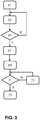
- Fig. 3 depicts a flowchart of a positioning and calibration method of the wearable ultrasound sensor probe 32, here a 2-D ultrasound sensor.
- the method commences in operation 61 with the provision of the wearable ultrasound sensor probe 32 after which the method proceeds to operation 63 in which the wearable ultrasound sensor probe 32 is manually positioned onto the body region of the patient by the caregiver and the wearable ultrasound sensor probe 32 is electronically calibrated, e.g. by systematic variation of the beam angle generated by the wearable ultrasound sensor probe 32 in order to detect an artery 36 of the patient in the Doppler ultrasound data generated with the wearable ultrasound sensor probe 32. It is checked in operation 65 if such an artery 36 can be detected. If such an artery 36 cannot be detected, the method returns to operation 63 in which the caregiver manually repositions the wearable ultrasound sensor probe 32 after which its electronic calibration is repeated until the artery 36 is found after which the method proceeds to operation 67.
- a region of interest close to the artery 36 is selected and in operation 69 a biplane view of the artery is generated to check alignment of the wearable ultrasound sensor probe 32 with the artery 36.
- the respective diameters of the artery 36 are evaluated systematically during manual repositioning, in operation 73, of the wearable ultrasound sensor probe 32 by the caregiver, optionally aided by acoustic guidance signals generated by the alarm generating unit 44. This iterative process in operations 71 and 73 is repeated until the maximum diameter of the artery 36 in both view planes is obtained, which is indicative of the optimal alignment of the wearable ultrasound sensor probe 32 with the artery 36.
- the method terminates in operation 75.
- the positioning and calibration method of a 3-D wearable ultrasound sensor probe 32 differs from the method as shown in Fig. 3 for a 2-D wearable ultrasound sensor 32 in that the manual repositioning in operation 73 to optimize the alignment of the wearable ultrasound sensor probe 32 with the artery 36 of the patient is replaced by an operation in which this repositioning is performed by electronic beam steering of the wearable 3-D ultrasound sensor probe 32.
- the above described methods executed by the processor 38 of the patient monitor controller 30 may be realized by computer readable program instructions embodied on a computer readable storage medium which, when executed on the processor arrangement, cause the processor arrangement to implement any embodiment of the method.
- Any suitable computer readable storage medium may be used for this purpose, such as for example an optically readable medium such as a CD, DVD or Blu-Ray disc, a magnetically readable medium such as a hard disk, an electronic data storage device such as a memory stick or the like, and so on.
- the computer readable storage medium may be a medium that is accessible over a network such as the Internet, such that the computer readable program instructions may be accessed over the network.
- the computer readable storage medium may be a network-attached storage device, a storage area network, cloud storage or the like.
- the computer readable storage medium may be an Internet-accessible service from which the computer readable program instructions may be obtained.
- the patient monitor controller 30 is adapted to retrieve the computer readable program instructions from such a computer readable storage medium and to create a new computer readable storage medium by storing the retrieved computer readable program instructions in a data storage arrangement of the patient monitor controller 30, e.g. in a memory device or the like forming part of the patient monitor controller 30.
- FIG. 4 shows an example of the components which may form a known ultrasound imaging system, which may be used in the system of the invention.
- a transducer array 106 of CMUT cells 108 as discussed above is for transmitting ultrasonic waves and receiving echo information.
- the transducer array 106 of the system 102 may generally be a one- or a two-dimensional array of transducer elements capable of scanning in a 2D plane or in three dimensions for 3D imaging. One such array may be used as each of the two or more probes of the invention.
- the transducer array 106 is coupled to a micro-beamformer 112 which controls transmission and reception of signals by the CMUT array cells.
- Micro-beamformers are capable of at least partial beamforming of the signals received by groups or "patches" of transducer elements for instance as described in US patents US 5,997,479 (Savord et al. ), US 6,013,032 (Savord ), and US 6,623,432 (Powers et al. ).
- the micro-beamformer 112 is coupled by the probe cable, e.g. coaxial wire, to a transmit/receive (T/R) switch 116 which switches between transmission and reception modes and protects the main beamformer 120 from high energy transmit signals when a micro-beamformer is not present or used and the transducer array 106 is operated directly by the main system beamformer 120.
- T/R transmit/receive
- the transmission of ultrasonic beams from the transducer array 106 under control of the micro-beamformer 112 is directed by a transducer controller 118 coupled to the micro-beamformer by the T/R switch 116 and the main system beamformer 120, which receives input from the user's operation of the user interface or control panel 138.
- One of the functions controlled by the transducer controller 118 is the direction in which beams are steered and focused. Beams may be steered straight ahead from (orthogonal to) the transducer array 106, or at different angles for a wider field of view.
- the transducer controller 118 may be coupled to control a voltage source 145 for the transducer array.
- the voltage source 145 sets DC and AC bias voltage(s) that are applied to the CMUT cells of a CMUT array 106, e.g. to generate the ultrasonic RF pulses in transmission mode.
- the partially beam-formed signals produced by the micro-beamformer 112 are forwarded to the main beamformer 120 where partially beam-formed signals from individual patches of transducer elements are combined into a fully beam-formed signal.
- the main beamformer 120 may have 128 channels, each of which receives a partially beam-formed signal from a patch of dozens or hundreds of CMUT transducer cells 108. In this way the signals received by thousands of transducer elements of a transducer array 106 can contribute efficiently to a single beam-formed signal.
- the beam-formed signals are coupled to a signal processor 122.
- the signal processor 122 can process the received echo signals in various ways, such as bandpass filtering, decimation, I and Q component separation, and harmonic signal separation which acts to separate linear and nonlinear signals so as to enable the identification of nonlinear (higher harmonics of the fundamental frequency) echo signals returned from tissue and microbubbles.
- the signal processor 122 optionally may perform additional signal enhancement such as speckle reduction, signal compounding, and noise elimination.
- the bandpass filter in the signal processor 122 may be a tracking filter, with its passband sliding from a higher frequency band to a lower frequency band as echo signals are received from increasing depths, thereby rejecting the noise at higher frequencies from greater depths where these frequencies are devoid of anatomical information.
- the processed signals are coupled to a B-mode processor 126 and to a Doppler processor 128.
- the B-mode processor 126 employs detection of an amplitude of the received ultrasound signal for the imaging of structures in the body such as the tissue of organs and vessels in the body.
- B-mode images of structure of the body may be formed in either the harmonic image mode or the fundamental image mode or a combination of both for instance as described in US Patents US 6,283,919 (Roundhill et al. ) and US 6,458,083 (Jago et al. ).
- the Doppler processor 128 processes temporally distinct signals from tissue movement and blood flow for the detection of the motion of substances, such as the flow of blood cells in the image field.
- the Doppler processor typically includes a wall filter with parameters which may be set to pass and/or reject echoes returned from selected types of materials in the body.
- the wall filter can be set to have a passband characteristic which passes signal of relatively low amplitude from higher velocity materials while rejecting relatively strong signals from lower or zero velocity material.
- This passband characteristic will pass signals from flowing blood while rejecting signals from nearby stationary or slowing moving objects such as the wall of the heart.
- An inverse characteristic would pass signals from moving tissue of the heart while rejecting blood flow signals for what is referred to as tissue Doppler imaging, detecting and depicting the motion of tissue.
- the Doppler processor receives and processes a sequence of temporally discrete echo signals from different points in an image field, the sequence of echoes from a particular point referred to as an ensemble.
- An ensemble of echoes received in rapid succession over a relatively short interval can be used to estimate the Doppler shift frequency of flowing blood, with the correspondence of the Doppler frequency to velocity indicating the blood flow velocity.
- An ensemble of echoes received over a longer period of time is used to estimate the velocity of slower flowing blood or slowly moving tissue.
- the structural and motion signals produced by the B-mode (and Doppler) processor(s) are coupled to a scan converter 132 and a multiplanar reformatter 144.
- the scan converter 132 arranges the echo signals in the spatial relationship from which they were received in a desired image format. For instance, the scan converter may arrange the echo signal into a two dimensional (2D) sector-shaped format, or a pyramidal three dimensional (3D) image.
- the scan converter can overlay a B-mode structural image with colors corresponding to motion at points in the image field with their Doppler-estimated velocities to produce a color Doppler image which depicts the motion of tissue and blood flow in the image field.
- the multiplanar reformatter 144 will convert echoes which are received from points in a common plane in a volumetric region of the body into an ultrasonic image of that plane, for instance as described in US Patent US 6,443,896 (Detmer ).
- a volume renderer 142 converts the echo signals of a 3D data set into a projected 3D image as viewed from a given reference point as described in US Pat. 6,530,885 (Entrekin et al. ).
- the 2D or 3D images are coupled from the scan converter 132, multiplanar reformatter 144, and volume renderer 142 to an image processor 130 for further enhancement, buffering and temporary storage for display on an image display 140.
- the blood flow values produced by the Doppler processor 128 and tissue structure information produced by the B-mode processor 126 are coupled to a quantification processor 134.
- the quantification processor produces measures of different flow conditions such as the volume rate of blood flow as well as structural measurements such as the sizes of organs and gestational age.
- the quantification processor may receive input from the user control panel 138, such as the point in the anatomy of an image where a measurement is to be made.
- Output data from the quantification processor is coupled to a graphics processor 136 for the reproduction of measurement graphics and values with the image on the display 140.
- the graphics processor 136 can also generate graphic overlays for display with the ultrasound images. These graphic overlays can contain standard identifying information such as patient name, date and time of the image, imaging parameters, and the like. For these purposes the graphics processor receives input from the user interface 138, such as patient name.
- the user interface is also coupled to the transmit controller 118 to control the generation of ultrasound signals from the transducer array 106 and hence the images produced by the transducer array and the ultrasound system.
- the user interface is also coupled to the multiplanar reformatter 144 for selection and control of the planes of multiple multiplanar reformatted (MPR) images which may be used to perform quantified measures in the image field of the MPR images.
- MPR multiplanar reformatted
- an ultrasonic diagnostic imaging system is intended to give a non-limiting example of such an ultrasonic diagnostic imaging system.
- the skilled person will immediately realize that several variations in the architecture of the ultrasonic diagnostic imaging system are feasible without departing from the teachings of the present invention.
- the micro-beamformer 112 may be omitted, the ultrasound probe 104 may not have 3D imaging capabilities and so on.
- FIG. 5 to 7 A preferred embodiment of the invention will now be described with reference to Figs. 5 to 7 . It will be understood that this may be incorporated in a system of the type described above with reference to Figs. 2 and 3 or Fig. 4 , by using two, or more than two, ultrasonic probes, and placing them at separate locations on the body of the patient to detect arterial flow and preferably also arterial diameter.
- Two or more low-cost ultrasound patches are each placed on the skin above a major artery (e.g. carotid and brachial), to detect the onset of centralization at an immediate stage, by monitoring blood flow redistribution.
- a major artery e.g. carotid and brachial
- the brachial flow is four times lower than the carotid flow.
- Flow in radial arteries and femoral arteries has its own typical ratio to the carotid flow. This ratio forms a patient- and cardiac output-independent measure of blood volume distribution.
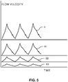
- FIG. 5 A simple example of how the signals can be analysed to detect volume (re)distribution is given in Fig. 5 .
- Carotid flow velocity C shown over three heart beats is compared with brachial flow velocity and the trace B1 where the numerical ratio is less than 2 (here about 1.2) is indicative of hypervolemia (centralization), the trace B2 where the ratio is 4 is indicative of normovolemia (no centralization), and the trace B3 where the ratio is greater than 8 is indicative of hypovolemia (centralization).
- the ratio in peak velocities is used, in this example, as a surrogate for the rate in 'stroke volumes' i.e. the volume of blood flowing through the artery in each heartbeat.
- the arterial diameter can either be found in calibration tables taking gender, age, height and weight into account, measured with a spot check a priori and entered into the monitor controller 30, or can be measured, as described above, with an ultrasound sensor probe 32 for example by imaging. Pulse wave Doppler imaging can be used for this purpose. The same probe can be used as is used for Doppler velocity measurement.
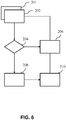
- Fig. 6 depicts schematically how the flow signals are input to an algorithm, run by a program in the processor 38 of the controller 30, that derives the blood volume (re)distribution.
- Blood flow signals for example the Doppler flow velocity signals shown in Fig. 5 , are obtained in steps 201 and 202 from the carotid and brachial (or other) arteries.
- the volume estimate at each location is calculated by integrating the Doppler velocity over each cycle, such as one heartbeat, and multiplying by an estimate of the arterial diameter as described above.
- the ratio e.g. Vbrachial / Vcarotid
- the program determines whether the ratio has been obtained for the first time in the current operation of the monitoring system since initialization.
- the first ratio in a time sequence of estimates is normally taken to be the reference ratio. If the first ratio is considered to be within the expected range (e.g. Vbrachial / Vcarotid is 3-5), then the ratio is set or reset in step 208 as the reference value. Consecutive ratios are compared to the reference value and stored in step 206 as the updated ratio. When the new ratio differs significantly from the reference (e.g. by 10% or more), a notification may be provided in step 210 as this indicates a change in blood volume distribution (an increase indicates centralization and a decrease indicates recovery or fluid overload). Furthermore, if the first ratio is far outside the expected range (e.g. Vbrachial / Vcarotid >6), then in step 210 a notification may be provided, as this may indicate centralization.
- the expected range e.g. Vbrachial / Vcarotid >6
- the reference value for the ratio of flow was taken to be 4; if that became more than 8 hypovolemia was indicated, and if it became less than 2 hypervolemia was indicated.
- This simple algorithm can be adapted by setting the ratio reference value in step 208, and using as upper and lower thresholds a predetermined percentage above and below this reference.
- step 210 is processed as one of the additional inputs 43 to the controller 30 of Fig. 2 , for example, to generate a haemodynamic display in the monitor 20 and optionally an alarm from unit 44.
- One outcome may be for the controller 30 automatically to signal a fluid management unit 46 such as a bedside controller to increase or decrease the rate of intravenous saline or plasma flow to the patient.
- a fluid management unit 46 such as a bedside controller to increase or decrease the rate of intravenous saline or plasma flow to the patient.
- the program traverses through the steps as shown in Fig. 7 , where a probe configuration is determined at initialization to set the number of probes and their locations. Consecutively, each probe is configured according to these positions; specifically the size of the scanning area (or volume) is set and the probe's pulse characteristics such as frequency, power and number of pulses.
- PW Pulsed Wave
- CW Continuous Wave
- three probes (patches) A, B and C similar to probe 32 are provided and are attached to the body over the carotid, brachial and femoral arteries respectively.
- the probes A, B and C are set up in steps 302, 304 and 306 and then in steps 308, 310 and 312 each probe performs a Doppler velocity measurement in the configured measurement area over a period that typically spans a heart cycle. From these measurements, a region of interest ROI and quality estimate of the detected flow follow.
- the ROI represents the estimated location of an artery through which flow is measured.
- the quality estimate is used to indicate if a reliable flow measurement can be performed.
- the probe configurations are all updated. For each probe, a possible probe configuration is determined to measure flow continuously. With these settings, in steps 316 and 318 the probes A and B are reconfigured (i.e. setting the probe's steering angle and driving scheme for focus and frequency) for optimal continuous flow measurement. This entails measuring the velocity in a specific region, updating the ROI to track possible movement of the artery (or the probe) and updating the phase estimate in the heart cycle. In case the quality of a scan was insufficient during initialization, following step 314 a probe, in this example probe C, can be temporarily disabled for continuous flow measurement, in step 320. For each enabled probe, the measurement parameters are updated and the scans are then performed in blocks 322 and 324 respectively, simultaneously.
- the region ROI is updated in step 326 and the scan period is updated in step 328.
- the region ROI is updated in step 332 and the scan period is updated in step 334.
- Doppler scanning is performed in steps 330 and 336.
- the flow data from these scans are processed in step 340 to determine the heart cycle period, and in step 350 to determine the (averaged) ratio over each heart cycle. In this example, the data from only the probes A and B are processed to derive the ratio.
- This routine shown in Figure 7 may be repeated regularly, for example at 15 minute intervals.
- the obtained flow signals can also be used to provide an estimate of cardiac output. This may be provided by the controller as an additional output for display on the monitor 20. In principle, this is also possible using only one ultrasound patch. When using only one patch, it should be placed on an artery through which the perfusion is highly dependent on the cardiac output.
- the brachial artery, or arteries downstream of that such as the radial artery, are good options.
- Fig. 8 blood flow is measured at the heart, line 401, and the kidney (renal artery), line 402, in addition to the carotid artery, line 10 and the brachial artery, line 12 which are the same as lines 10 and 12 in Fig. 1 .
- the pressure range over which changes can be measured is large, but the resolution/accuracy is low. Adding a probe on an artery with flow properties that behave like the lines 10 and 402, between the extremes, would improve the accuracy of the measurements.
- the change in diameter of the inferior vena cava (IVC) for example may give additional information on the fluid status of the patient, and could be used together with the monitoring of the changes described according to the invention.
- IVC inferior vena cava
- An aspect of this disclosure is the diagnostic method of taking and using blood flow measurements at two different locations on the body.
- This method of detecting the onset of hypovolemia (and/or hypervolemia) comprises taking Doppler ultrasound measurements of arterial blood flow velocity in at least two different locations of a subject, preferably simultaneously or in quick succession, to obtain a measure of the blood flow at each location, monitoring changes in a predetermined function of the blood flow measures, and providing an output indicative of the monitored changes.
- the output preferably includes information on whether the monitored changes indicate hypovolemia or hypervolemia.
- controllers can be implemented in numerous ways, with software and/or hardware, to perform the various functions required.
- a processor is one example of a controller which employs one or more microprocessors that may be programmed using software (e.g., microcode) to perform the required functions.
- a controller may however be implemented with or without employing a processor, and also may be implemented as a combination of dedicated hardware to perform some functions and a processor (e.g., one or more programmed microprocessors and associated circuitry) to perform other functions.
- controller is separate from the probes in the embodiments described, its functionality could instead be integrated into one or more of the probes.
- the communications between the probes and the controller are described as wireless in the embodiments, but they could be wired, by having cables between the probes or between the probes and the controller, or both.
- the probes could be powered from an external source such as the controller, and need not then have internal power sources.
- wired connections could make the usage of the probes more difficult and painful.
- the probes are conveniently mounted as patches on the surface of the skin.
- the invention could use more invasive techniques, such as probes within the subject's tissue.
- controller components that may be employed in various embodiments of the present disclosure include, but are not limited to, conventional microprocessors, application specific integrated circuits (ASICs), and field-programmable gate arrays (FPGAs).
- ASICs application specific integrated circuits
- FPGAs field-programmable gate arrays
- a processor or controller may be associated with one or more storage media such as volatile and non-volatile computer memory such as RAM, PROM, EPROM, and EEPROM.
- the storage media may be encoded with one or more programs that, when executed on one or more processors and/or controllers, perform the required functions.
- Various storage media may be fixed within a processor or controller or may be transportable, such that the one or more programs stored thereon can be loaded into a processor or controller.
Landscapes
- Health & Medical Sciences (AREA)
- Life Sciences & Earth Sciences (AREA)
- Engineering & Computer Science (AREA)
- Public Health (AREA)
- Medical Informatics (AREA)
- Biomedical Technology (AREA)
- General Health & Medical Sciences (AREA)
- Pathology (AREA)
- Surgery (AREA)
- Radiology & Medical Imaging (AREA)
- Molecular Biology (AREA)
- Physics & Mathematics (AREA)
- Animal Behavior & Ethology (AREA)
- Nuclear Medicine, Radiotherapy & Molecular Imaging (AREA)
- Biophysics (AREA)
- Veterinary Medicine (AREA)
- Heart & Thoracic Surgery (AREA)
- Hematology (AREA)
- Data Mining & Analysis (AREA)
- Epidemiology (AREA)
- Primary Health Care (AREA)
- Physiology (AREA)
- Computer Vision & Pattern Recognition (AREA)
- Databases & Information Systems (AREA)
- Ultra Sonic Daignosis Equipment (AREA)
- Measuring Pulse, Heart Rate, Blood Pressure Or Blood Flow (AREA)
Priority Applications (6)
| Application Number | Priority Date | Filing Date | Title |
|---|---|---|---|
| EP18155683.8A EP3524165A1 (fr) | 2018-02-08 | 2018-02-08 | Contrôle de la distribution de sang chez un sujet |
| PCT/EP2019/052769 WO2019154805A1 (fr) | 2018-02-08 | 2019-02-05 | Surveillance de la distribution du sang chez un sujet |
| CN201980017805.8A CN111818854B (zh) | 2018-02-08 | 2019-02-05 | 监测对象中的血液分布 |
| US16/967,555 US11896421B2 (en) | 2018-02-08 | 2019-02-05 | Monitoring blood distribution in a subject |
| EP19702291.6A EP3749209B1 (fr) | 2018-02-08 | 2019-02-05 | Contrôle de la distribution de sang chez un sujet |
| JP2020542639A JP7486426B2 (ja) | 2018-02-08 | 2019-02-05 | 被験者における血液分布のモニタリング |
Applications Claiming Priority (1)
| Application Number | Priority Date | Filing Date | Title |
|---|---|---|---|
| EP18155683.8A EP3524165A1 (fr) | 2018-02-08 | 2018-02-08 | Contrôle de la distribution de sang chez un sujet |
Publications (1)
| Publication Number | Publication Date |
|---|---|
| EP3524165A1 true EP3524165A1 (fr) | 2019-08-14 |
Family
ID=61192685
Family Applications (2)
| Application Number | Title | Priority Date | Filing Date |
|---|---|---|---|
| EP18155683.8A Withdrawn EP3524165A1 (fr) | 2018-02-08 | 2018-02-08 | Contrôle de la distribution de sang chez un sujet |
| EP19702291.6A Active EP3749209B1 (fr) | 2018-02-08 | 2019-02-05 | Contrôle de la distribution de sang chez un sujet |
Family Applications After (1)
| Application Number | Title | Priority Date | Filing Date |
|---|---|---|---|
| EP19702291.6A Active EP3749209B1 (fr) | 2018-02-08 | 2019-02-05 | Contrôle de la distribution de sang chez un sujet |
Country Status (5)
| Country | Link |
|---|---|
| US (1) | US11896421B2 (fr) |
| EP (2) | EP3524165A1 (fr) |
| JP (1) | JP7486426B2 (fr) |
| CN (1) | CN111818854B (fr) |
| WO (1) | WO2019154805A1 (fr) |
Families Citing this family (12)
| Publication number | Priority date | Publication date | Assignee | Title |
|---|---|---|---|---|
| CN112399865B (zh) | 2018-03-09 | 2022-09-27 | 1929803安大略Dba 弗洛索尼克斯医疗公司 | 动态可控的患者流体控制装置 |
| US20220133269A1 (en) * | 2019-02-28 | 2022-05-05 | The Regents Of The University Of California | Integrated wearable ultrasonic phased arrays for monitoring |
| CN115361908A (zh) * | 2019-11-26 | 2022-11-18 | 蝴蝶运营公司 | 用于脉冲波多普勒超声成像的方法和装置 |
| WO2022008970A1 (fr) | 2020-07-06 | 2022-01-13 | 1929803 Ontario Corp. D/B/A Flosonics Medical | Timbre à ultrasons comprenant un ensemble transducteur souple intégré |
| US12036065B2 (en) * | 2021-02-04 | 2024-07-16 | Orbicor Technologies Sociedad Anonima | Modular wireless system for multi-point synchronous measurement of cardiac and vascular indicators, their function and the differences over time |
| KR20230106315A (ko) * | 2022-01-06 | 2023-07-13 | 한국과학기술연구원 | 부착 가능한 패치형 초음파 트랜스듀서를 활용한 진단 시스템 |
| WO2024115639A1 (fr) | 2022-12-02 | 2024-06-06 | Koninklijke Philips N.V. | Détermination d'un profil d'écoulement dans une artère sur la base de données d'imagerie par ultrasons |
| WO2024151750A1 (fr) * | 2023-01-10 | 2024-07-18 | Edwards Lifesciences Corporation | Estimateur de risque de lésion rénale aiguë |
| WO2024151758A1 (fr) * | 2023-01-10 | 2024-07-18 | Edwards Lifesciences Corporation | Technique de suivi de flux à l'aide d'ultrasons |
| CN120813305A (zh) * | 2023-02-06 | 2025-10-17 | 加利福尼亚大学董事会 | 使用适形超声贴片的经颅体积成像 |
| WO2025230899A1 (fr) * | 2024-04-29 | 2025-11-06 | Becton, Dickinson And Company | Méthode et systèmes pour réduire le temps de recherche d'une cible dans un doppler ultrasonore autonome |
| US20260108227A1 (en) * | 2024-10-22 | 2026-04-23 | National Yang Ming Chiao Tung University | Method and system for estimating energetic hemodynamic parameters and computer readable medium thereof |
Citations (9)
| Publication number | Priority date | Publication date | Assignee | Title |
|---|---|---|---|---|
| US5997479A (en) | 1998-05-28 | 1999-12-07 | Hewlett-Packard Company | Phased array acoustic systems with intra-group processors |
| US6013032A (en) | 1998-03-13 | 2000-01-11 | Hewlett-Packard Company | Beamforming methods and apparatus for three-dimensional ultrasound imaging using two-dimensional transducer array |
| US6283919B1 (en) | 1996-11-26 | 2001-09-04 | Atl Ultrasound | Ultrasonic diagnostic imaging with blended tissue harmonic signals |
| US6443896B1 (en) | 2000-08-17 | 2002-09-03 | Koninklijke Philips Electronics N.V. | Method for creating multiplanar ultrasonic images of a three dimensional object |
| US6458083B1 (en) | 1996-11-26 | 2002-10-01 | Koninklijke Philips Electronics N.V. | Ultrasonic harmonic imaging with adaptive image formation |
| US6530885B1 (en) | 2000-03-17 | 2003-03-11 | Atl Ultrasound, Inc. | Spatially compounded three dimensional ultrasonic images |
| US6623432B2 (en) | 2000-08-24 | 2003-09-23 | Koninklijke Philips Electronics N.V. | Ultrasonic diagnostic imaging transducer with hexagonal patches |
| US20100312115A1 (en) | 2009-06-05 | 2010-12-09 | General Electric Company | System and method for monitoring hemodynamic state |
| WO2016077765A1 (fr) * | 2014-11-13 | 2016-05-19 | Vanderbilt University | Dispositif et procédé de détection d'hémorragie et de réanimation guidé et applications associées |
Family Cites Families (14)
| Publication number | Priority date | Publication date | Assignee | Title |
|---|---|---|---|---|
| US4424814A (en) | 1981-03-30 | 1984-01-10 | Jeffrey Secunda | Perfusion ratio detector |
| IL137045A0 (en) * | 2000-06-27 | 2001-06-14 | Gorenberg Nora Viviana | A non-invasive method and apparatus for measuring the mechanical performance of the heart |
| JP5076203B2 (ja) * | 2001-06-21 | 2012-11-21 | 学校法人日本大学 | 血管疾患検査装置およびバイパス血管診断装置 |
| JP5300171B2 (ja) * | 2005-06-30 | 2013-09-25 | 株式会社東芝 | 超音波診断装置、超音波画像処理装置及び超音波画像処理プログラム |
| JP4892732B2 (ja) * | 2007-03-28 | 2012-03-07 | 国立大学法人岐阜大学 | 血管画像化方法、血管画像化システム及び血管画像化プログラム |
| US8246546B2 (en) * | 2008-09-30 | 2012-08-21 | General Electric Company | Method, arrangement and apparatus for monitoring fluid balance status of a subject |
| EP2506760B1 (fr) | 2009-12-03 | 2015-09-16 | Deltex Medical Limited | Procédé et dispositif de surveillance hémodynamique qui utilise une mesure combinée de débit sanguin et de pression sanguine |
| WO2013005179A1 (fr) | 2011-07-05 | 2013-01-10 | Koninklijke Philips Electronics N.V. | Procédé, dispositif et système pour la détermination de l'instant auquel le statut d'une artère passe d'un état ouvert à un état fermé et inversement pour une artère d'intérêt sous une pression de modification |
| WO2013110929A1 (fr) | 2012-01-26 | 2013-08-01 | King's College London | Mesure de vitesse de l'onde de pouls aortique |
| JP2013252423A (ja) | 2012-05-08 | 2013-12-19 | Seiko Epson Corp | 心拍出量モニター装置および心拍出量測定方法 |
| WO2017093150A1 (fr) * | 2015-12-02 | 2017-06-08 | Koninklijke Philips N.V. | Appareil de surveillance et procédé de surveillance pour déterminer des informations de signes vitaux d'un sujet |
| JP6914934B2 (ja) * | 2015-12-10 | 2021-08-04 | 1929803 オンタリオ コーポレイション ディー/ビー/エー ケーイー2 テクノロジーズ | 自動化された流体応答測定のためのシステムおよび方法 |
| US11020092B2 (en) * | 2015-12-22 | 2021-06-01 | Koninklijke Philips N.V. | Multi-site concurrent ultrasound blood flow velocity measurement for continuous hemodynamic management |
| GB201604873D0 (en) * | 2016-03-22 | 2016-05-04 | Imp Innovations Ltd | Fluid flow analysis |
-
2018
- 2018-02-08 EP EP18155683.8A patent/EP3524165A1/fr not_active Withdrawn
-
2019
- 2019-02-05 WO PCT/EP2019/052769 patent/WO2019154805A1/fr not_active Ceased
- 2019-02-05 JP JP2020542639A patent/JP7486426B2/ja active Active
- 2019-02-05 US US16/967,555 patent/US11896421B2/en active Active
- 2019-02-05 CN CN201980017805.8A patent/CN111818854B/zh active Active
- 2019-02-05 EP EP19702291.6A patent/EP3749209B1/fr active Active
Patent Citations (9)
| Publication number | Priority date | Publication date | Assignee | Title |
|---|---|---|---|---|
| US6283919B1 (en) | 1996-11-26 | 2001-09-04 | Atl Ultrasound | Ultrasonic diagnostic imaging with blended tissue harmonic signals |
| US6458083B1 (en) | 1996-11-26 | 2002-10-01 | Koninklijke Philips Electronics N.V. | Ultrasonic harmonic imaging with adaptive image formation |
| US6013032A (en) | 1998-03-13 | 2000-01-11 | Hewlett-Packard Company | Beamforming methods and apparatus for three-dimensional ultrasound imaging using two-dimensional transducer array |
| US5997479A (en) | 1998-05-28 | 1999-12-07 | Hewlett-Packard Company | Phased array acoustic systems with intra-group processors |
| US6530885B1 (en) | 2000-03-17 | 2003-03-11 | Atl Ultrasound, Inc. | Spatially compounded three dimensional ultrasonic images |
| US6443896B1 (en) | 2000-08-17 | 2002-09-03 | Koninklijke Philips Electronics N.V. | Method for creating multiplanar ultrasonic images of a three dimensional object |
| US6623432B2 (en) | 2000-08-24 | 2003-09-23 | Koninklijke Philips Electronics N.V. | Ultrasonic diagnostic imaging transducer with hexagonal patches |
| US20100312115A1 (en) | 2009-06-05 | 2010-12-09 | General Electric Company | System and method for monitoring hemodynamic state |
| WO2016077765A1 (fr) * | 2014-11-13 | 2016-05-19 | Vanderbilt University | Dispositif et procédé de détection d'hémorragie et de réanimation guidé et applications associées |
Non-Patent Citations (2)
| Title |
|---|
| PHILIPPE ARBEILLE: "Doppler sensors and harnesses for cardiac and peripheral arterial flow monitoring", ULTRASOUND IN MEDICINE & BIOLOGY, vol. 23, no. 3, 1 January 1997 (1997-01-01), pages 415 - 423, XP055099549, ISSN: 0301-5629, DOI: 10.1016/S0301-5629(96)00225-6 * |
| W MAIXNER ET AL: "Early detection of hypovolemia from directional arterial flow velocity", CIRC SHOCK, 1 January 1978 (1978-01-01), pages 35 - 41, XP055497975, Retrieved from the Internet <URL:http://www.ncbi.nlm.nih.gov/pubmed/647868> [retrieved on 20180807] * |
Also Published As
| Publication number | Publication date |
|---|---|
| JP2021513401A (ja) | 2021-05-27 |
| EP3749209A1 (fr) | 2020-12-16 |
| CN111818854B (zh) | 2025-02-11 |
| EP3749209B1 (fr) | 2022-08-17 |
| US20210085280A1 (en) | 2021-03-25 |
| US11896421B2 (en) | 2024-02-13 |
| WO2019154805A1 (fr) | 2019-08-15 |
| CN111818854A (zh) | 2020-10-23 |
| JP7486426B2 (ja) | 2024-05-17 |
Similar Documents
| Publication | Publication Date | Title |
|---|---|---|
| EP3749209B1 (fr) | Contrôle de la distribution de sang chez un sujet | |
| Goddi et al. | Vector flow imaging techniques: An innovative ultrasonographic technique for the study of blood flow | |
| EP4164501B1 (fr) | Procédé permettant d'estimer des paramètres hémodynamiques | |
| JP7029013B2 (ja) | 患者モニタリング | |
| JP6783863B2 (ja) | 血行管理のためのマルチサイト連続超音波流量測定 | |
| US20130303916A1 (en) | Cardiac output monitoring system and cardiac output measurement method | |
| WO2013042029A1 (fr) | Schémas d'excitation pour réseaux de transducteurs à faible coût | |
| Cinthio et al. | Intra-observer variability of longitudinal displacement and intramural shear strain measurements of the arterial wall using ultrasound noninvasively in vivo | |
| CN112930145B (zh) | 超声控制单元 | |
| CN113660901B (zh) | 颅内血压估计方法和设备 | |
| JP5148203B2 (ja) | 超音波診断装置 | |
| JP4679141B2 (ja) | 超音波診断装置および超音波診断画像の表示方法 | |
| KR20180096342A (ko) | 초음파 영상장치 및 그 제어방법 | |
| US20230105837A1 (en) | Ultrasound diagnostic apparatus, method for controlling ultrasound diagnostic apparatus, and non-transitory computer-readable recording medium storing program for controlling ultrasound diagnostic apparatus | |
| EP3773231B1 (fr) | Système et procédé d'imagerie par ultrasons | |
| RU2800255C2 (ru) | Блок управления ультразвуковыми исследованиями | |
| JP2023028891A (ja) | 生体情報処理方法、生体情報処理装置及びプログラム |
Legal Events
| Date | Code | Title | Description |
|---|---|---|---|
| PUAI | Public reference made under article 153(3) epc to a published international application that has entered the european phase |
Free format text: ORIGINAL CODE: 0009012 |
|
| AK | Designated contracting states |
Kind code of ref document: A1 Designated state(s): AL AT BE BG CH CY CZ DE DK EE ES FI FR GB GR HR HU IE IS IT LI LT LU LV MC MK MT NL NO PL PT RO RS SE SI SK SM TR |
|
| AX | Request for extension of the european patent |
Extension state: BA ME |
|
| RAP1 | Party data changed (applicant data changed or rights of an application transferred) |
Owner name: KONINKLIJKE PHILIPS N.V. |
|
| STAA | Information on the status of an ep patent application or granted ep patent |
Free format text: STATUS: THE APPLICATION IS DEEMED TO BE WITHDRAWN |
|
| 18D | Application deemed to be withdrawn |
Effective date: 20200215 |