EP3524449A1 - Partie de suspension d'un véhicule automobile ainsi que procédé de fabrication d'une partie de suspension - Google Patents
Partie de suspension d'un véhicule automobile ainsi que procédé de fabrication d'une partie de suspension Download PDFInfo
- Publication number
- EP3524449A1 EP3524449A1 EP18155672.1A EP18155672A EP3524449A1 EP 3524449 A1 EP3524449 A1 EP 3524449A1 EP 18155672 A EP18155672 A EP 18155672A EP 3524449 A1 EP3524449 A1 EP 3524449A1
- Authority
- EP
- European Patent Office
- Prior art keywords
- component
- chassis part
- carrier element
- fiber
- plastic composite
- Prior art date
- Legal status (The legal status is an assumption and is not a legal conclusion. Google has not performed a legal analysis and makes no representation as to the accuracy of the status listed.)
- Granted
Links
Images


Classifications
-
- B—PERFORMING OPERATIONS; TRANSPORTING
- B60—VEHICLES IN GENERAL
- B60G—VEHICLE SUSPENSION ARRANGEMENTS
- B60G7/00—Pivoted suspension arms; Accessories thereof
- B60G7/001—Suspension arms, e.g. constructional features
-
- B—PERFORMING OPERATIONS; TRANSPORTING
- B60—VEHICLES IN GENERAL
- B60G—VEHICLE SUSPENSION ARRANGEMENTS
- B60G2200/00—Indexing codes relating to suspension types
- B60G2200/10—Independent suspensions
- B60G2200/18—Multilink suspensions, e.g. elastokinematic arrangements
- B60G2200/182—Multilink suspensions, e.g. elastokinematic arrangements with one longitudinal arm or rod and lateral rods
-
- B—PERFORMING OPERATIONS; TRANSPORTING
- B60—VEHICLES IN GENERAL
- B60G—VEHICLE SUSPENSION ARRANGEMENTS
- B60G2204/00—Indexing codes related to suspensions per se or to auxiliary parts
- B60G2204/40—Auxiliary suspension parts; Adjustment of suspensions
- B60G2204/43—Fittings, brackets or knuckles
-
- B—PERFORMING OPERATIONS; TRANSPORTING
- B60—VEHICLES IN GENERAL
- B60G—VEHICLE SUSPENSION ARRANGEMENTS
- B60G2206/00—Indexing codes related to the manufacturing of suspensions: constructional features, the materials used, procedures or tools
- B60G2206/01—Constructional features of suspension elements, e.g. arms, dampers, springs
- B60G2206/013—Constructional features of suspension elements, e.g. arms, dampers, springs with embedded inserts for material reinforcement
-
- B—PERFORMING OPERATIONS; TRANSPORTING
- B60—VEHICLES IN GENERAL
- B60G—VEHICLE SUSPENSION ARRANGEMENTS
- B60G2206/00—Indexing codes related to the manufacturing of suspensions: constructional features, the materials used, procedures or tools
- B60G2206/01—Constructional features of suspension elements, e.g. arms, dampers, springs
- B60G2206/10—Constructional features of arms
-
- B—PERFORMING OPERATIONS; TRANSPORTING
- B60—VEHICLES IN GENERAL
- B60G—VEHICLE SUSPENSION ARRANGEMENTS
- B60G2206/00—Indexing codes related to the manufacturing of suspensions: constructional features, the materials used, procedures or tools
- B60G2206/01—Constructional features of suspension elements, e.g. arms, dampers, springs
- B60G2206/50—Constructional features of wheel supports or knuckles, e.g. steering knuckles, spindle attachments
-
- B—PERFORMING OPERATIONS; TRANSPORTING
- B60—VEHICLES IN GENERAL
- B60G—VEHICLE SUSPENSION ARRANGEMENTS
- B60G2206/00—Indexing codes related to the manufacturing of suspensions: constructional features, the materials used, procedures or tools
- B60G2206/01—Constructional features of suspension elements, e.g. arms, dampers, springs
- B60G2206/70—Materials used in suspensions
- B60G2206/71—Light weight materials
- B60G2206/7101—Fiber-reinforced plastics [FRP]
Definitions
- the invention relates to a chassis part of a motor vehicle, in particular a wheel carrier, comprising a fiber-reinforced plastic composite with a metallic support member, wherein the support member is formed of a plurality of perforations having sheet metal. Furthermore, the invention relates to a method for producing a chassis part, in particular a wheel carrier.
- Fiber-reinforced plastic composites in chassis parts of motor vehicles is basically known.
- Carbon fibers are used as materials for the fibers, which are arranged, for example, unidirectional or quasi-isotropic in the fiber-reinforced plastic composite.
- a unidirectional arrangement of the fibers means that all fibers of a layer of the plastic composite are oriented in a single direction.
- a quasi-isotropic arrangement of the fibers means that the fibers of a layer of the plastic composite are oriented in different directions.
- Wheel carriers are chassis parts which form that part of the wheel suspension of a motor vehicle which receives a wheel journal or a wheel bearing and thus a wheel of the motor vehicle.
- the wheel carrier usually, the wheel carrier numerous recordings for connecting the wheel carrier with other components, such as a wishbone, a caliper or a trailing arm, on.
- Chassis parts made of a fiber-reinforced plastic composite have advantages in terms of weight and possibly also in terms of stiffness compared to the metallic materials commonly used for suspension parts.
- suspension parts, which from a fiber-reinforced plastic composite are produced without a carrier element, insufficient strength properties for the intended use of certain chassis parts, such as wheel carriers, may have.
- a chassis part made of a fiber-reinforced plastic composite tends to brittle fracture at impact loads, which occur, for example, when a motor vehicle with a wheel in a pothole or over a curb drives. By such a shock-like load, a chassis part can be damaged so that it can no longer fulfill the function of the chassis part, which brings a significant risk to the occupants of the motor vehicle especially with safety-relevant chassis parts.
- the purpose of the steel wires is to ensure that an extremely high impact load of the component by plastic deformation of the same is visible, which is not the case with corresponding components of fiber reinforced plastic, which have no steel wires, and at a further high load to an uncontrolled breaking of the fiber reinforced plastic component can lead.
- a disadvantage of such a configuration is that the load capacity of such reinforced by thin steel wires component in the chassis of a motor vehicle substantially does not differ from the load capacity of a component made of a fiber-reinforced plastic composite without steel wire insert.
- the present invention has the object to provide a chassis part of the type mentioned, which has a high component strength and can be produced inexpensively with savings of material weight.
- chassis part with the features specified in claim 1.
- Preferred and advantageous embodiments of the chassis part according to the invention are specified in the subclaims.
- the chassis part according to the invention which comprises a fiber-reinforced plastic composite with a metallic support member, wherein the support member is formed of a plurality of perforations having metal sheet, characterized in that the fiber-reinforced plastic composite composed of at least two different components, wherein a first component of the plastic composite is arranged on a first side of the support member and wherein a second component of the plastic composite is disposed on a side opposite the first side of the support member, wherein the first component is formed of fiber-reinforced plastic with continuous fibers, and wherein the second component of fiber-reinforced plastic with discontinuous fibers is trained.
- continuous fibers have high stiffness and strength values depending on the direction. Accordingly, the first component, which is formed of fiber-reinforced plastic with continuous fibers, absorb high forces in the direction of the continuous fibers. Discontinuous fibers can not accommodate such high directional forces, however, the multidirectional force absorption of the discontinuous fiber is greater, especially with random orientation of the discontinuous fibers.
- the term continuous fiber does not mean that the fibers so designated have an endless length, but rather that the length of the fibers so designated is above a certain minimum length. Preferably, this minimum length is 50 mm.
- the length of the continuous fibers is in a range between 20 and 50 mm.
- the length of the discontinuous fibers is less than the length of the continuous fibers used in the plastic composite of the chassis part.
- the first side of the carrier element is, for example, the underside or outside of the carrier element.
- the first side of the carrier element is understood here as the side of the carrier element which is turned down or out in the assembled state or intended use of the chassis part. In the side opposite the first side of the support member is then the top or inside of the chassis part.
- direction-dependent forces occur, in particular on the underside or outside of chassis parts, which can preferably be absorbed by endless fibers of the fiber-reinforced plastic composite in the chassis part according to the invention.
- frequently or more direction-independent forces occur on the upper side or inner side of chassis parts, which in the case of the chassis part according to the invention can preferably be absorbed by unidirectional fibers of the fiber-reinforced plastic composite.
- the inventive design of a chassis part thus sufficient for the intended use strength of the component can be provided, being saved by the provision of two components of fiber-reinforced plastic material weight.
- the hybrid composition of the chassis part can also save material and production costs.
- the fibers of the fiber-reinforced plastic used are preferably carbon fibers, also called carbon fibers.
- a single carbon fiber typically has a diameter in the range of 5 to 9 microns.
- 12K fibers are used for the continuous fibers. This means that about 12,000 fibers are combined into a single yarn.
- 15K fibers are preferably used for the discontinuous fibers. This means that about 15,000 fibers are combined to form a multifilament yarn.
- a preferred embodiment of the invention is characterized in that the carrier element and / or the first component and / or the second component of the fiber-reinforced plastic composite does not extend over the entire length and / or width of the chassis part. It is particularly advantageous if, according to a preferred embodiment of the invention, the first component is arranged on the underside or outside of the carrier element and extends over the entire length of the chassis part. The second component is arranged in this case on the top or inside of the support member, wherein the support member and the second component does not extend over the entire length of the chassis part. This is particularly advantageous because larger forces can be absorbed in a substantially two-dimensional direction by means of the first component. In addition, many chassis parts on areas that do not have to absorb such large forces that there would be a support element and / or a second component of a fiber-reinforced plastic composite would be necessary to absorb these forces.
- the second component of the fiber-reinforced plastic composite is preferably or in particular arranged in those areas of the chassis part, which have a three-dimensional structure (shape).
- the three-dimensional structure (shape) may have, for example, webs projecting from a base surface or fork-shaped receptacles for the articulated connection of the chassis part.
- the discontinuous fibers of the fiber-reinforced plastic composite are well suited.
- a further preferred embodiment of the invention is characterized in that the carrier element is formed from a formed metal sheet, wherein the underside or outside of the carrier element is formed substantially two-dimensionally and wherein the top or inside of the carrier element has a three-dimensional structure (shape).
- the shape of the chassis part preferably corresponds at least partially substantially to the shape of the deformed metal sheet, so that the first component of the fiber-reinforced plastic composite, which is preferably arranged on the underside or outside of the carrier element (metal sheet), can absorb or absorb forces in a two-dimensional direction, in particular Transverse and longitudinal direction of the support element.
- the first component of the fiber-reinforced plastic composite is particularly suitable due to their continuous fibers, so that a high component strength and rigidity is achieved.
- the upper side of the carrier element has a three-dimensional structure (shape) which is reinforced or stiffened by means of the second component of the fiber-reinforced plastic composite. This is ensured in particular by the provision of the discontinuous fibers in the second component, since in this way forces can be absorbed in each component direction.
- a two-dimensional design of the underside or outside of the carrier element does not mean that the underside or outside of the carrier element may lie exclusively in a two-dimensional plane. Rather, the two-dimensional design of the underside or outer side of the carrier element means that the underside of the carrier element has no clear projection, but is substantially smooth or flat.
- a further preferred embodiment of the invention is characterized in that the continuous fibers are formed as unidirectional and continuous filaments, wherein the continuous fibers preferably extend in the longitudinal direction of the chassis part.
- the longitudinal direction of the chassis part is to be understood as meaning the longitudinal extent of the relevant motor vehicle or the longitudinal extent of the chassis part.
- the first component of the plastic composite preferably has a thickness in the range from 0.1 to 0.3 mm, particularly preferably in the range from 0.15 to 0.25 mm, and is composed of 9 to 13 layers, preferably 10 to 12 Layers, more preferably composed of 11 layers, unidirectional and continuous filaments together.
- the fibers of adjacent layers can be oriented in the same direction or in different directions.
- the fibers of adjacent layers are oriented in the same direction.
- the fibers of adjacent layers are each aligned orthogonal to each other, wherein the continuous fibers preferably extend in the longitudinal and in the transverse direction of the chassis part.
- a further preferred embodiment of the invention is characterized in that the continuous fibers are formed as bidirectional and continuous filaments, wherein the continuous fibers are preferably aligned substantially orthogonal to each other and preferably extend in the longitudinal and transverse direction of the chassis part.
- the forces occurring in the longitudinal direction and in the transverse direction of the chassis part can be reliably absorbed by the continuous fibers of the first component of the fiber-reinforced plastic composite.
- the longitudinal direction of the chassis part is in turn the longitudinal direction of the motor vehicle or to understand the longitudinal extent of the chassis part. Accordingly, the transverse direction of the vehicle part or the transverse extension of the chassis part is to be understood as meaning the transverse direction of the chassis part.
- the first component of the plastic composite preferably has a thickness in the range from 0.2 to 0.6 mm, particularly preferably in the range from 0.3 to 0.5 mm, and is composed of 6 to 10 layers, preferably 7 to 9 Layers, more preferably composed of 8 layers, bidirectional and continuous filaments together.
- the fibers of adjacent layers can be oriented in the same direction or in different directions.
- the continuous fibers account for a proportion of 43 to 63 vol .-%, preferably from 48 to 58 vol .-%, of the first component of the fiber-reinforced plastic composite according to a further preferred embodiment of the invention.
- a proportion of continuous fibers is sufficient to provide high strength values of the chassis component.
- the other constituents of the first component of the fiber-reinforced plastic composite may be, for example, thermosetting synthetic resins or thermoplastics.
- a further advantageous embodiment of the invention is characterized in that the second component of the fiber-reinforced plastic composite has isotropic properties.
- Isotropic properties mean that the mechanical properties of the discontinuous fibers having second component of the plastic composite are not or only slightly dependent on the direction of the force.
- the orientation of the discontinuous fibers is preferably random and does not follow a specific pattern.
- the second which is preferably arranged on the upper side of the metallic support element, has a second one Component of the fiber reinforced plastic composite increased strength regardless of the direction of the applied force.
- a stiffening of the arranged in particular on the upper side of the metallic support member three-dimensional structure is made possible.
- the discontinuous fibers make up a proportion of 30 to 50% by volume, preferably 35 to 45% by volume, of the second component of the fiber-reinforced plastic composite.
- a proportion of continuous fibers is sufficient to provide high strength values of the chassis component.
- the other constituents of the second component may be, for example, thermosetting synthetic resins or thermoplastics.
- the second component of the fiber-reinforced plastic composite preferably has a thickness in the range of 1 to 10 mm.
- a further preferred embodiment of the invention is characterized in that the first component and the second component of the fiber-reinforced plastic composite via the openings of the support member (metal sheet) are integrally connected to each other, and that the plastic composite is positively connected to the carrier element.
- the contact points of the first and second components are preferably arranged in the openings of the carrier element, wherein the two components are preferably connected by the contact points cohesively with each other.
- the carrier element is positively connected to the plastic composite formed by the first component and the second component.
- the first component and the second component of the fiber-reinforced plastic composite of thermosetting synthetic resin, preferably polyester resin, epoxy resin, phenolic resin, polyurethane resin and / or methyl methacrylate, and / or thermoplastic, preferably polyamide, polyphenylene sulfide, polybutylene terephthalate, Polyethylene terephthalate and / or polyetheretherketone formed, wherein the first component preferably comprises epoxy resin and wherein the second component preferably comprises vinyl ester resin.
- a further advantageous embodiment of the invention provides that the carrier element has a perforated surface portion formed by the perforations, which is 60 to 90%, preferably 70 to 80%, of the base area of the carrier element.
- the base surface of the carrier element is preferably formed by the substantially 2-dimensional surface of the underside of the carrier element without openings.
- a hole area proportion in the above-mentioned order of magnitude allows a stable connection between the two layers (components of the fiber-reinforced plastic composite) as well as a sufficient stabilization of the two layers by the carrier element.
- a chassis component with a low weight can be provided by the relatively high hole area proportion, since the metallic support member has a higher density than the two components of the fiber-reinforced plastic composite.
- the apertures have a hexagonal or circular hole shape, and that the hole size of the respective aperture is in a range of 100 to 250 mm 2 , preferably in a range of 150 to 200 mm 2 , particularly preferably in a range of 170 to 180 mm 2 , lies.
- a hexagonal hole shape is particularly advantageous for weight reduction of the chassis component, whereas a circular hole shape is more advantageous for the production technical production of the chassis component is.
- the largest width or the diameter of an opening is about 15 mm.
- the metal sheet of the support member has a thickness in the range of 1 to 4 mm, preferably in the range of about 2 to 3.5 mm, wherein the metal sheet has a yield strength in a range of about 100 to 500 N / mm 2 , preferably in a range of 200 to 400 N / mm 2 .
- the yield strength is a material characteristic, and therefore, the above-mentioned value range of the yield strength generally refers to the yield strength of the material of the metal sheet and not to the yield strength of the metal sheet having openings.
- the above object is also achieved by an initially mentioned method for producing a chassis part, in particular a wheel carrier, in which a metallic carrier element is formed in a forming step, wherein the metallic carrier element before or after the forming step in at least one punching step with a plurality is provided by openings, and in which a first fiber composite component with a second fiber composite component in a flow-pressing step via the openings is materially connected.
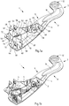
- Fig. 1a shows a chassis part 1, which is designed in the form of a wheel carrier.
- the chassis part 1 or the wheel carrier can be provided for example for a rear axle or a front axle of a motor vehicle and comprises a fiber-reinforced plastic composite, which is composed of at least two different components 2 and 6, wherein between the first component 2 and the second component 6 is a metallic Carrier element 4 is integrated (see Fig. 1b and 2 ).
- the three-dimensional chassis part 1 is preferably manufactured substantially in a single process step by means of extrusion molding from the two different plastic components 2 and 6, which have different reinforcing fibers, and the metallic carrier element 4 serving as insert.
- the first fiber-reinforced plastic component 2 is preferably preformed in a preceding manufacturing step (forming step) and then together with the metallic support member 4 and a plastic material which can be formed by extrusion, having reinforcing fibers, which finally forms the second component 6 of the plastic composite, into a pressing tool inserted and pressed together with the carrier element 4 and the plastic material.
- the carrier element 4 is in particular in Fig. 3 shown. It consists of a formed and perforated metal sheet, preferably sheet steel.
- the metal sheet (steel sheet) has a sheet thickness in the range of about 1 to 3.5 mm.
- the yield strength of the metal sheet used for producing the carrier element 4 is, for example, in the range of about 300 to 400 MPa (N / mm 2 ).
- the carrier element 4 has a substantially flat or slightly curved base or base 26, on the one side tabs 42 and at least one web 50 protrude.
- the base or base 26 is provided with a plurality of openings 28, wherein a plurality of these openings 28 has a hexagonal hole shape.
- the hole surface portion resulting from the sum of the perforations 28 is, for example, approximately 60 to 80% of the base area 26 of the metallic carrier element 4.
- the plastic resins of the two components 2 and 6 connect to each other and cure after extrusion cohesively.
- the two fiber-reinforced components 2 and 6, which are connected to one another in a materially cohesive connection form a positive connection with the perforated metallic carrier element 4 after curing.
- the carrier element 4 has a wheel bearing receptacle 30, which comprises a recess 32 with a relatively large diameter and, for example, four smaller through holes 34.
- the through holes 34 are spaced from each other on a common pitch circle surrounding the recess 32.
- the substantially circular recess 32 is provided with a nose-shaped indentation 36.
- the tabs 42 or webs 50 projecting on one side from the base surface 26 define a three-dimensional structure 38 of the carrier element 4.
- the tabs 42 form fork-shaped connecting sections 40 for connecting the chassis part 1 with suspension arms, for example transverse control arms or a tie rod.
- 42 through-holes 44, 46 and 48 are formed for receiving screws or hinge pins in the tabs.
- the through holes 44 are used, for example, the connection of the chassis part 1 to an upper control arm, while the through holes 46 serve the connection of the chassis part 1 to a rear, lower wishbone.
- the through holes 48 can be used to connect the chassis part 1 to a front, lower arm or to a tie rod.
- the tabs 42 are bent substantially perpendicular to the base surface 26 of the support member 4, wherein the also substantially perpendicular to the base 26 bent-edge web (wall portion) 50 connects two of the tabs 42 integrally with each other.
- the first component 2 of the fiber-reinforced plastic composite has a greater elongated extent than the carrier element 4 and also as the second component 6.
- the relative to the support member 4 and the second component 6 additional length of the first component 2 is substantially formed by an L-shaped portion of the first component 2, which defines an arm 8 of the chassis part 1, wherein on one side, for example, the top or Inner side of the arm 8, preferably a reinforced area 10 is formed.
- the reinforced area 10 serves to reinforce the arm 8 formed from the first component 2 in such a way that the arm 8 has sufficient rigidity and strength to absorb the forces acting on the arm 8.
- the L-shaped arm 8 has a first, curved arm portion 7 and a second arm portion 9, wherein at the end of the curved arm portion 7, a bearing eye 12 is arranged, for example, the articulated connection of the Chassis part 1 is used to an axle.
- the bearing eye 12 is preferably carried out substantially circular or circular cylindrical and has on both sides axially projecting collar.
- the first arm portion 7 is formed substantially plate-shaped.
- the second arm portion 9 has a recess 14, which reduces the weight of the chassis part 1 and can serve, for example, the passage of a brake line.
- the recess 14 is formed substantially elliptical.
- the first component 2 of the plastic composite has a substantially planar surface 16, which is provided with a wheel bearing receiving area 18.
- the wheel bearing receiving portion 18 includes a substantially circular recess 20 and four through holes distributed around the recess 20.
- the size, shape and arrangement of the recess 20 and the through holes 22 of the component 2 correspond to the size, shape and arrangement of the recess 32 and through holes 34 the metallic support member 4, so that the recesses 20 and 32 and the through holes 22 and 34 are aligned in coverage.
- the surface 16 has two additional through holes 24. These can be used to mount on the chassis part 1 other components, such as a brake plate.
- the first component 2 of the plastic composite is, for example, shaped such that its wheel bearing receiving portion 18 lies in a different plane than its curved, the bearing eye 12 having arm portion 7, these two portions are integrally connected by the second arm portion 9.
- the second component 6 of the plastic composite produced by flow presses covers the metallic carrier element 4 and the wheel bearing receiving section 18 of the first component 2 of the plastic composite.
- the peripheral edges of the two components 2 and 6 are partially contour-parallel and substantially edgewise, wherein the second component 6 ends at the recess 14 of the arm portion 9 of the first component 2.
- the wheel bearing receiving portion 52 of the second component 6 includes, similar to the wheel bearing receiving portion 18 of the first component, a substantially circular recess 54 and four distributed around the recess 54 through holes 56.
- the size, shape and arrangement of the recess 54 and the through holes 56 correspond again the size, shape and arrangement of the recess 32 and through holes 34 of the metallic support member 4, so that the recesses 54, 32 and 20 and the through holes 56, 34 and 22 are aligned in overlap.
- the second component 6 of the plastic composite surrounds the tabs 42 of the metallic carrier element 4 and the web 50 connecting the tabs 42.
- the second component 6 of the plastic composite produced by extrusion thus has a three-dimensional structure consisting of a substantially flat base surface and webs 58 projecting therefrom is formed, wherein two webs 58 define a connection portion 60 for connecting the chassis part 1 with suspension arms, such as wishbones, or a tie rod.
- 58 through-holes 62, 64 and 66 are provided in the webs, which are aligned with the through holes 44, 46 and 48 of the support member 4.
- the webs 58 having the through holes 62, 64 and 66 are connected to one another by wall sections 68, the wall sections 68 having round rod-shaped thickenings 70 running perpendicular to the base surface of the second component 6. These thickenings 70 cause a stabilization of the wall sections 68 and thus of the chassis part 1.
- 6 through-holes 72 are formed in the second component, which are aligned with the through holes 24 formed in the first component 2.
- Fig. 4a is a sectional plane of a portion of the first component 2 of the plastic composite shown schematically.
- the sectional plane extends substantially parallel to the surface of the base 16 of the first component 2.
- the first component 2 exclusively substantially unidirectionally arranged endless fibers 74. These are oriented in an illustrated layer 76 of the first component 2 in the longitudinal direction L of the chassis part 1.
- Q denotes the transverse direction.
- the endless fibers 74 do not extend over the entire length of the shown portion of the first component 2 and also do not all have the same length, but that all continuous fibers 74 have a certain minimum length.
- Fig. 4b schematically shows a layer 78 or sectional plane of a portion of the second component 6 of the plastic composite.
- the cutting plane also runs parallel to the surface area of the second component 2 shown.
- the layer 78 has discontinuous fibers 80, which have a significantly shorter length than the endless fibers 74 of the first component 2.
- the discontinuous fibers 80 have no common orientation direction, but are randomly distributed in the layer 78.
- the first component 2 of the fiber-reinforced plastic composite is composed of several layers, for example 9 to 13 layers, preferably 10 to 12 layers, and more preferably 11 layers 76 of unidirectional continuous fibers 74.
- the continuous fibers 74 make up a proportion of, for example, about 43 to 63% by volume, preferably from 48 to 58% by volume, of the first component 2.
Landscapes
- Engineering & Computer Science (AREA)
- Mechanical Engineering (AREA)
- Body Structure For Vehicles (AREA)
Priority Applications (1)
| Application Number | Priority Date | Filing Date | Title |
|---|---|---|---|
| EP18155672.1A EP3524449B1 (fr) | 2018-02-08 | 2018-02-08 | Partie de suspension d'un véhicule automobile ainsi que procédé de fabrication d'une partie de suspension |
Applications Claiming Priority (1)
| Application Number | Priority Date | Filing Date | Title |
|---|---|---|---|
| EP18155672.1A EP3524449B1 (fr) | 2018-02-08 | 2018-02-08 | Partie de suspension d'un véhicule automobile ainsi que procédé de fabrication d'une partie de suspension |
Publications (2)
| Publication Number | Publication Date |
|---|---|
| EP3524449A1 true EP3524449A1 (fr) | 2019-08-14 |
| EP3524449B1 EP3524449B1 (fr) | 2021-03-31 |
Family
ID=61188644
Family Applications (1)
| Application Number | Title | Priority Date | Filing Date |
|---|---|---|---|
| EP18155672.1A Active EP3524449B1 (fr) | 2018-02-08 | 2018-02-08 | Partie de suspension d'un véhicule automobile ainsi que procédé de fabrication d'une partie de suspension |
Country Status (1)
| Country | Link |
|---|---|
| EP (1) | EP3524449B1 (fr) |
Cited By (1)
| Publication number | Priority date | Publication date | Assignee | Title |
|---|---|---|---|---|
| US20180361810A1 (en) * | 2017-06-14 | 2018-12-20 | Ford Global Technologies, Llc | Wheel carrier for a vehicle suspension |
Citations (9)
| Publication number | Priority date | Publication date | Assignee | Title |
|---|---|---|---|---|
| US4772044A (en) * | 1983-08-22 | 1988-09-20 | Booher Benjamin V | Vehicle suspension system with flexible control arm |
| EP0851131A2 (fr) * | 1996-12-26 | 1998-07-01 | Tenneco Automotive Inc. | Barre de torsion de polymère remplie renforcée par de l'acier |
| WO2008028647A1 (fr) * | 2006-09-05 | 2008-03-13 | Johnson Controls Gmbh | Élément de véhicule à structure hybride |
| DE102007015616A1 (de) * | 2007-03-29 | 2008-10-09 | Zf Friedrichshafen Ag | Verbindungsstück zum gelenkigen Verbinden von im Fahrwerk eines Fahrzeugs angeordneten Bauelementen |
| DE102011086890A1 (de) | 2011-11-22 | 2013-05-23 | Bayerische Motoren Werke Aktiengesellschaft | Bauelement im Fahrwerk eines Kraftfahrzeugs |
| DE102012207487A1 (de) * | 2012-05-07 | 2013-11-07 | Bayerische Motoren Werke Aktiengesellschaft | Fahrwerks-Lenker aus faserverstärktem Kunststoffmaterial |
| WO2014195484A2 (fr) * | 2013-06-07 | 2014-12-11 | Aktiebolaget Skf | Fusée d'essieu comprenant un renforcement à base de fibres |
| DE102013222775A1 (de) * | 2013-11-08 | 2015-05-13 | Bayerische Motoren Werke Aktiengesellschaft | Radträger in Faserverbundbauweise |
| DE102015209001A1 (de) * | 2015-05-15 | 2016-11-17 | Ford Global Technologies, Llc | Radaufhängungseinheit für ein Kraftfahrzeug |
-
2018
- 2018-02-08 EP EP18155672.1A patent/EP3524449B1/fr active Active
Patent Citations (9)
| Publication number | Priority date | Publication date | Assignee | Title |
|---|---|---|---|---|
| US4772044A (en) * | 1983-08-22 | 1988-09-20 | Booher Benjamin V | Vehicle suspension system with flexible control arm |
| EP0851131A2 (fr) * | 1996-12-26 | 1998-07-01 | Tenneco Automotive Inc. | Barre de torsion de polymère remplie renforcée par de l'acier |
| WO2008028647A1 (fr) * | 2006-09-05 | 2008-03-13 | Johnson Controls Gmbh | Élément de véhicule à structure hybride |
| DE102007015616A1 (de) * | 2007-03-29 | 2008-10-09 | Zf Friedrichshafen Ag | Verbindungsstück zum gelenkigen Verbinden von im Fahrwerk eines Fahrzeugs angeordneten Bauelementen |
| DE102011086890A1 (de) | 2011-11-22 | 2013-05-23 | Bayerische Motoren Werke Aktiengesellschaft | Bauelement im Fahrwerk eines Kraftfahrzeugs |
| DE102012207487A1 (de) * | 2012-05-07 | 2013-11-07 | Bayerische Motoren Werke Aktiengesellschaft | Fahrwerks-Lenker aus faserverstärktem Kunststoffmaterial |
| WO2014195484A2 (fr) * | 2013-06-07 | 2014-12-11 | Aktiebolaget Skf | Fusée d'essieu comprenant un renforcement à base de fibres |
| DE102013222775A1 (de) * | 2013-11-08 | 2015-05-13 | Bayerische Motoren Werke Aktiengesellschaft | Radträger in Faserverbundbauweise |
| DE102015209001A1 (de) * | 2015-05-15 | 2016-11-17 | Ford Global Technologies, Llc | Radaufhängungseinheit für ein Kraftfahrzeug |
Cited By (2)
| Publication number | Priority date | Publication date | Assignee | Title |
|---|---|---|---|---|
| US20180361810A1 (en) * | 2017-06-14 | 2018-12-20 | Ford Global Technologies, Llc | Wheel carrier for a vehicle suspension |
| US10717334B2 (en) * | 2017-06-14 | 2020-07-21 | Ford Global Technologies, Llc | Wheel carrier for a vehicle suspension |
Also Published As
| Publication number | Publication date |
|---|---|
| EP3524449B1 (fr) | 2021-03-31 |
Similar Documents
| Publication | Publication Date | Title |
|---|---|---|
| EP2759423B1 (fr) | Bras oscillant transversal en plastique renforcé en fibres pour une suspension de roue d'un véhicule | |
| DE102012213050B4 (de) | Leichtgewichtige Fahrzeugräder mit Karbonfasereinsätzen | |
| DE112016001778B4 (de) | Strukturbaugruppe für eine Fahrzeugsitz-Rückenlehne | |
| EP2039487B1 (fr) | Composant à structure fibreuse, composant de robot, robot industriel, composant composite général, composants composites pour véhicules terrestres, spatiaux et aéronefs et procédé de fabrication d'un composant à structure fibreuse | |
| EP3550171B1 (fr) | Dispositif de ressort à lame pour véhicule et procédé de fabrication d'un tel dispositif de ressort à lame | |
| WO2003039892A1 (fr) | Jambe de force | |
| DE102018202307B4 (de) | Lenker für eine Radaufhängung | |
| DE10006400A1 (de) | Scheibenrad und Verfahren zu dessen Herstellung | |
| DE102011077336A1 (de) | Radaufhängungselement, umfassend zumindest eine Tragstruktur und einen Lenker | |
| DE10153875A1 (de) | Bauteil in langgestreckter Bauweise aus einem Faser-Kunststoff-Verbund | |
| EP3007959B1 (fr) | Longeron d'un seul tenant pour véhicules à moteur | |
| EP3007958B1 (fr) | Support d'essieu d'un véhicule comportant un élément de renforcement en matériau composite renforcé par des fibres | |
| WO2015086379A2 (fr) | Ensemble composé d'un élément de châssis et d'un élément d'assemblage et procédé pour fixer une élément d'assemblage à un élément de châssis | |
| DE102015209001A1 (de) | Radaufhängungseinheit für ein Kraftfahrzeug | |
| DE102016211212A1 (de) | Achsstrebe für ein Fahrzeug | |
| EP3524449B1 (fr) | Partie de suspension d'un véhicule automobile ainsi que procédé de fabrication d'une partie de suspension | |
| EP3287297B1 (fr) | Roue pour un véhicule à entraînement musculaire ayant des rayons collés côté jante | |
| DE102021108564B4 (de) | Bauteil eines Kraftfahrzeugs | |
| DE102016210074A1 (de) | Längslenker für eine Radaufhängung sowie Radaufhängung mit Längslenker | |
| DE102017102562A1 (de) | Verbindungselement zur Anbindung eines Bauteils an eine Faserverbundstruktur | |
| DE102019206217A1 (de) | Fahrwerklenker | |
| DE102014216021A1 (de) | Verstärktes Strukturelement für ein Kraftfahrzeug | |
| EP2505702B2 (fr) | Lisse dotée d'un corps de lisse formé par sections de plusieurs couches de feuilles | |
| DE102007062326A1 (de) | Ladeboden für ein Kraftfahrzeug | |
| DE202016103191U1 (de) | Längslenker für eine Radaufhängung sowie Radaufhängung mit Längslenker |
Legal Events
| Date | Code | Title | Description |
|---|---|---|---|
| PUAI | Public reference made under article 153(3) epc to a published international application that has entered the european phase |
Free format text: ORIGINAL CODE: 0009012 |
|
| STAA | Information on the status of an ep patent application or granted ep patent |
Free format text: STATUS: THE APPLICATION HAS BEEN PUBLISHED |
|
| AK | Designated contracting states |
Kind code of ref document: A1 Designated state(s): AL AT BE BG CH CY CZ DE DK EE ES FI FR GB GR HR HU IE IS IT LI LT LU LV MC MK MT NL NO PL PT RO RS SE SI SK SM TR |
|
| AX | Request for extension of the european patent |
Extension state: BA ME |
|
| STAA | Information on the status of an ep patent application or granted ep patent |
Free format text: STATUS: REQUEST FOR EXAMINATION WAS MADE |
|
| 17P | Request for examination filed |
Effective date: 20200211 |
|
| RBV | Designated contracting states (corrected) |
Designated state(s): AL AT BE BG CH CY CZ DE DK EE ES FI FR GB GR HR HU IE IS IT LI LT LU LV MC MK MT NL NO PL PT RO RS SE SI SK SM TR |
|
| GRAP | Despatch of communication of intention to grant a patent |
Free format text: ORIGINAL CODE: EPIDOSNIGR1 |
|
| STAA | Information on the status of an ep patent application or granted ep patent |
Free format text: STATUS: GRANT OF PATENT IS INTENDED |
|
| INTG | Intention to grant announced |
Effective date: 20201015 |
|
| GRAS | Grant fee paid |
Free format text: ORIGINAL CODE: EPIDOSNIGR3 |
|
| GRAA | (expected) grant |
Free format text: ORIGINAL CODE: 0009210 |
|
| STAA | Information on the status of an ep patent application or granted ep patent |
Free format text: STATUS: THE PATENT HAS BEEN GRANTED |
|
| RAP1 | Party data changed (applicant data changed or rights of an application transferred) |
Owner name: AUTOTECH ENGINEERING DEUTSCHLAND GMBH Owner name: GESTAMP TALLENT LTD Owner name: AUTOTECH ENGINEERING S.L. |
|
| AK | Designated contracting states |
Kind code of ref document: B1 Designated state(s): AL AT BE BG CH CY CZ DE DK EE ES FI FR GB GR HR HU IE IS IT LI LT LU LV MC MK MT NL NO PL PT RO RS SE SI SK SM TR |
|
| REG | Reference to a national code |
Ref country code: GB Ref legal event code: FG4D Free format text: NOT ENGLISH Ref country code: CH Ref legal event code: EP |
|
| REG | Reference to a national code |
Ref country code: AT Ref legal event code: REF Ref document number: 1376530 Country of ref document: AT Kind code of ref document: T Effective date: 20210415 |
|
| REG | Reference to a national code |
Ref country code: DE Ref legal event code: R096 Ref document number: 502018004489 Country of ref document: DE |
|
| REG | Reference to a national code |
Ref country code: IE Ref legal event code: FG4D Free format text: LANGUAGE OF EP DOCUMENT: GERMAN |
|
| REG | Reference to a national code |
Ref country code: LT Ref legal event code: MG9D |
|
| PG25 | Lapsed in a contracting state [announced via postgrant information from national office to epo] |
Ref country code: FI Free format text: LAPSE BECAUSE OF FAILURE TO SUBMIT A TRANSLATION OF THE DESCRIPTION OR TO PAY THE FEE WITHIN THE PRESCRIBED TIME-LIMIT Effective date: 20210331 Ref country code: HR Free format text: LAPSE BECAUSE OF FAILURE TO SUBMIT A TRANSLATION OF THE DESCRIPTION OR TO PAY THE FEE WITHIN THE PRESCRIBED TIME-LIMIT Effective date: 20210331 Ref country code: NO Free format text: LAPSE BECAUSE OF FAILURE TO SUBMIT A TRANSLATION OF THE DESCRIPTION OR TO PAY THE FEE WITHIN THE PRESCRIBED TIME-LIMIT Effective date: 20210630 Ref country code: BG Free format text: LAPSE BECAUSE OF FAILURE TO SUBMIT A TRANSLATION OF THE DESCRIPTION OR TO PAY THE FEE WITHIN THE PRESCRIBED TIME-LIMIT Effective date: 20210630 |
|
| PG25 | Lapsed in a contracting state [announced via postgrant information from national office to epo] |
Ref country code: SE Free format text: LAPSE BECAUSE OF FAILURE TO SUBMIT A TRANSLATION OF THE DESCRIPTION OR TO PAY THE FEE WITHIN THE PRESCRIBED TIME-LIMIT Effective date: 20210331 Ref country code: RS Free format text: LAPSE BECAUSE OF FAILURE TO SUBMIT A TRANSLATION OF THE DESCRIPTION OR TO PAY THE FEE WITHIN THE PRESCRIBED TIME-LIMIT Effective date: 20210331 Ref country code: LV Free format text: LAPSE BECAUSE OF FAILURE TO SUBMIT A TRANSLATION OF THE DESCRIPTION OR TO PAY THE FEE WITHIN THE PRESCRIBED TIME-LIMIT Effective date: 20210331 |
|
| REG | Reference to a national code |
Ref country code: NL Ref legal event code: MP Effective date: 20210331 |
|
| PG25 | Lapsed in a contracting state [announced via postgrant information from national office to epo] |
Ref country code: LT Free format text: LAPSE BECAUSE OF FAILURE TO SUBMIT A TRANSLATION OF THE DESCRIPTION OR TO PAY THE FEE WITHIN THE PRESCRIBED TIME-LIMIT Effective date: 20210331 Ref country code: EE Free format text: LAPSE BECAUSE OF FAILURE TO SUBMIT A TRANSLATION OF THE DESCRIPTION OR TO PAY THE FEE WITHIN THE PRESCRIBED TIME-LIMIT Effective date: 20210331 Ref country code: CZ Free format text: LAPSE BECAUSE OF FAILURE TO SUBMIT A TRANSLATION OF THE DESCRIPTION OR TO PAY THE FEE WITHIN THE PRESCRIBED TIME-LIMIT Effective date: 20210331 Ref country code: SM Free format text: LAPSE BECAUSE OF FAILURE TO SUBMIT A TRANSLATION OF THE DESCRIPTION OR TO PAY THE FEE WITHIN THE PRESCRIBED TIME-LIMIT Effective date: 20210331 Ref country code: NL Free format text: LAPSE BECAUSE OF FAILURE TO SUBMIT A TRANSLATION OF THE DESCRIPTION OR TO PAY THE FEE WITHIN THE PRESCRIBED TIME-LIMIT Effective date: 20210331 |
|
| PG25 | Lapsed in a contracting state [announced via postgrant information from national office to epo] |
Ref country code: IS Free format text: LAPSE BECAUSE OF FAILURE TO SUBMIT A TRANSLATION OF THE DESCRIPTION OR TO PAY THE FEE WITHIN THE PRESCRIBED TIME-LIMIT Effective date: 20210731 Ref country code: PL Free format text: LAPSE BECAUSE OF FAILURE TO SUBMIT A TRANSLATION OF THE DESCRIPTION OR TO PAY THE FEE WITHIN THE PRESCRIBED TIME-LIMIT Effective date: 20210331 Ref country code: PT Free format text: LAPSE BECAUSE OF FAILURE TO SUBMIT A TRANSLATION OF THE DESCRIPTION OR TO PAY THE FEE WITHIN THE PRESCRIBED TIME-LIMIT Effective date: 20210802 Ref country code: RO Free format text: LAPSE BECAUSE OF FAILURE TO SUBMIT A TRANSLATION OF THE DESCRIPTION OR TO PAY THE FEE WITHIN THE PRESCRIBED TIME-LIMIT Effective date: 20210331 Ref country code: SK Free format text: LAPSE BECAUSE OF FAILURE TO SUBMIT A TRANSLATION OF THE DESCRIPTION OR TO PAY THE FEE WITHIN THE PRESCRIBED TIME-LIMIT Effective date: 20210331 |
|
| REG | Reference to a national code |
Ref country code: DE Ref legal event code: R097 Ref document number: 502018004489 Country of ref document: DE |
|
| PG25 | Lapsed in a contracting state [announced via postgrant information from national office to epo] |
Ref country code: ES Free format text: LAPSE BECAUSE OF FAILURE TO SUBMIT A TRANSLATION OF THE DESCRIPTION OR TO PAY THE FEE WITHIN THE PRESCRIBED TIME-LIMIT Effective date: 20210331 Ref country code: DK Free format text: LAPSE BECAUSE OF FAILURE TO SUBMIT A TRANSLATION OF THE DESCRIPTION OR TO PAY THE FEE WITHIN THE PRESCRIBED TIME-LIMIT Effective date: 20210331 Ref country code: AL Free format text: LAPSE BECAUSE OF FAILURE TO SUBMIT A TRANSLATION OF THE DESCRIPTION OR TO PAY THE FEE WITHIN THE PRESCRIBED TIME-LIMIT Effective date: 20210331 |
|
| PLBE | No opposition filed within time limit |
Free format text: ORIGINAL CODE: 0009261 |
|
| STAA | Information on the status of an ep patent application or granted ep patent |
Free format text: STATUS: NO OPPOSITION FILED WITHIN TIME LIMIT |
|
| 26N | No opposition filed |
Effective date: 20220104 |
|
| PG25 | Lapsed in a contracting state [announced via postgrant information from national office to epo] |
Ref country code: IS Free format text: LAPSE BECAUSE OF FAILURE TO SUBMIT A TRANSLATION OF THE DESCRIPTION OR TO PAY THE FEE WITHIN THE PRESCRIBED TIME-LIMIT Effective date: 20210731 |
|
| PG25 | Lapsed in a contracting state [announced via postgrant information from national office to epo] |
Ref country code: IT Free format text: LAPSE BECAUSE OF FAILURE TO SUBMIT A TRANSLATION OF THE DESCRIPTION OR TO PAY THE FEE WITHIN THE PRESCRIBED TIME-LIMIT Effective date: 20210331 |
|
| PG25 | Lapsed in a contracting state [announced via postgrant information from national office to epo] |
Ref country code: MC Free format text: LAPSE BECAUSE OF FAILURE TO SUBMIT A TRANSLATION OF THE DESCRIPTION OR TO PAY THE FEE WITHIN THE PRESCRIBED TIME-LIMIT Effective date: 20210331 |
|
| REG | Reference to a national code |
Ref country code: CH Ref legal event code: PL |
|
| REG | Reference to a national code |
Ref country code: BE Ref legal event code: MM Effective date: 20220228 |
|
| PG25 | Lapsed in a contracting state [announced via postgrant information from national office to epo] |
Ref country code: LU Free format text: LAPSE BECAUSE OF NON-PAYMENT OF DUE FEES Effective date: 20220208 |
|
| PG25 | Lapsed in a contracting state [announced via postgrant information from national office to epo] |
Ref country code: LI Free format text: LAPSE BECAUSE OF NON-PAYMENT OF DUE FEES Effective date: 20220228 Ref country code: IE Free format text: LAPSE BECAUSE OF NON-PAYMENT OF DUE FEES Effective date: 20220208 Ref country code: CH Free format text: LAPSE BECAUSE OF NON-PAYMENT OF DUE FEES Effective date: 20220228 |
|
| PG25 | Lapsed in a contracting state [announced via postgrant information from national office to epo] |
Ref country code: BE Free format text: LAPSE BECAUSE OF NON-PAYMENT OF DUE FEES Effective date: 20220228 |
|
| REG | Reference to a national code |
Ref country code: AT Ref legal event code: MM01 Ref document number: 1376530 Country of ref document: AT Kind code of ref document: T Effective date: 20230208 |
|
| PG25 | Lapsed in a contracting state [announced via postgrant information from national office to epo] |
Ref country code: AT Free format text: LAPSE BECAUSE OF NON-PAYMENT OF DUE FEES Effective date: 20230208 |
|
| PG25 | Lapsed in a contracting state [announced via postgrant information from national office to epo] |
Ref country code: MK Free format text: LAPSE BECAUSE OF FAILURE TO SUBMIT A TRANSLATION OF THE DESCRIPTION OR TO PAY THE FEE WITHIN THE PRESCRIBED TIME-LIMIT Effective date: 20210331 Ref country code: CY Free format text: LAPSE BECAUSE OF FAILURE TO SUBMIT A TRANSLATION OF THE DESCRIPTION OR TO PAY THE FEE WITHIN THE PRESCRIBED TIME-LIMIT Effective date: 20210331 Ref country code: AT Free format text: LAPSE BECAUSE OF NON-PAYMENT OF DUE FEES Effective date: 20230208 |
|
| PG25 | Lapsed in a contracting state [announced via postgrant information from national office to epo] |
Ref country code: HU Free format text: LAPSE BECAUSE OF FAILURE TO SUBMIT A TRANSLATION OF THE DESCRIPTION OR TO PAY THE FEE WITHIN THE PRESCRIBED TIME-LIMIT; INVALID AB INITIO Effective date: 20180208 |
|
| PG25 | Lapsed in a contracting state [announced via postgrant information from national office to epo] |
Ref country code: TR Free format text: LAPSE BECAUSE OF FAILURE TO SUBMIT A TRANSLATION OF THE DESCRIPTION OR TO PAY THE FEE WITHIN THE PRESCRIBED TIME-LIMIT Effective date: 20210331 |
|
| PG25 | Lapsed in a contracting state [announced via postgrant information from national office to epo] |
Ref country code: MT Free format text: LAPSE BECAUSE OF FAILURE TO SUBMIT A TRANSLATION OF THE DESCRIPTION OR TO PAY THE FEE WITHIN THE PRESCRIBED TIME-LIMIT Effective date: 20210331 |
|
| PG25 | Lapsed in a contracting state [announced via postgrant information from national office to epo] |
Ref country code: GR Free format text: LAPSE BECAUSE OF NON-PAYMENT OF DUE FEES Effective date: 20210331 |
|
| PG25 | Lapsed in a contracting state [announced via postgrant information from national office to epo] |
Ref country code: GR Free format text: LAPSE BECAUSE OF NON-PAYMENT OF DUE FEES Effective date: 20210331 |
|
| PGFP | Annual fee paid to national office [announced via postgrant information from national office to epo] |
Ref country code: FR Payment date: 20250225 Year of fee payment: 8 |
|
| PGFP | Annual fee paid to national office [announced via postgrant information from national office to epo] |
Ref country code: GB Payment date: 20260227 Year of fee payment: 9 |
|
| PGFP | Annual fee paid to national office [announced via postgrant information from national office to epo] |
Ref country code: DE Payment date: 20260227 Year of fee payment: 9 |
|
| PGFP | Annual fee paid to national office [announced via postgrant information from national office to epo] |
Ref country code: AT Payment date: 20260410 Year of fee payment: 5 |