EP3524760B1 - Hebelraste - Google Patents
Hebelraste Download PDFInfo
- Publication number
- EP3524760B1 EP3524760B1 EP19156165.3A EP19156165A EP3524760B1 EP 3524760 B1 EP3524760 B1 EP 3524760B1 EP 19156165 A EP19156165 A EP 19156165A EP 3524760 B1 EP3524760 B1 EP 3524760B1
- Authority
- EP
- European Patent Office
- Prior art keywords
- lever
- pin
- support body
- spring
- elongated plate
- Prior art date
- Legal status (The legal status is an assumption and is not a legal conclusion. Google has not performed a legal analysis and makes no representation as to the accuracy of the status listed.)
- Active
Links
- 238000003801 milling Methods 0.000 description 4
- 230000006835 compression Effects 0.000 description 1
- 238000007906 compression Methods 0.000 description 1
- 230000005489 elastic deformation Effects 0.000 description 1
- 238000003780 insertion Methods 0.000 description 1
- 230000037431 insertion Effects 0.000 description 1
- 238000004519 manufacturing process Methods 0.000 description 1
- 239000007769 metal material Substances 0.000 description 1
- 238000000465 moulding Methods 0.000 description 1
- 230000035515 penetration Effects 0.000 description 1
- 230000001681 protective effect Effects 0.000 description 1
- 239000002023 wood Substances 0.000 description 1
Images


Classifications
-
- E—FIXED CONSTRUCTIONS
- E05—LOCKS; KEYS; WINDOW OR DOOR FITTINGS; SAFES
- E05C—BOLTS OR FASTENING DEVICES FOR WINGS, SPECIALLY FOR DOORS OR WINDOWS
- E05C1/00—Fastening devices with bolts moving rectilinearly
- E05C1/02—Fastening devices with bolts moving rectilinearly without latching action
- E05C1/06—Fastening devices with bolts moving rectilinearly without latching action with operating handle or equivalent member moving otherwise than rigidly with the bolt
- E05C1/065—Fastening devices with bolts moving rectilinearly without latching action with operating handle or equivalent member moving otherwise than rigidly with the bolt flush
-
- E—FIXED CONSTRUCTIONS
- E05—LOCKS; KEYS; WINDOW OR DOOR FITTINGS; SAFES
- E05B—LOCKS; ACCESSORIES THEREFOR; HANDCUFFS
- E05B63/00—Locks or fastenings with special structural characteristics
- E05B63/06—Locks or fastenings with special structural characteristics with lengthwise-adjustable bolts ; with adjustable backset, i.e. distance from door edge
-
- E—FIXED CONSTRUCTIONS
- E05—LOCKS; KEYS; WINDOW OR DOOR FITTINGS; SAFES
- E05B—LOCKS; ACCESSORIES THEREFOR; HANDCUFFS
- E05B15/00—Other details of locks; Parts for engagement by bolts of fastening devices
- E05B15/04—Spring arrangements in locks
- E05B2015/0458—Leaf springs; Non-wound wire springs
Definitions
- the present invention regards a lever latch, in particular for hinged leaves, according to the preamble of the relative independent claim.
- the present latch is advantageously employable for fixing - to a fixed frame, to the floor or to the ceiling - hinged leaves for example of doors, front/security doors, French windows or the like.
- the present latch is advantageously intended to be used with double-leaf windows/shutters/doors, e.g. of semi-fixed type and flanking a door, of which one leaf is movable and one fixable by means of such latch in a closed position in which it is susceptible of receiving the movable leaf in abutment.
- the latch subject of the present invention, is therefore inserted in the field of production of accessories for windows/shutters/doors.
- pairs of lever latches mounted on the section of a first leaf are widely known and diffused, generally in order to lock the leaf to the floor and to the ceiling - and against such section, a second movable leaf is susceptible of abutting when it reaches the closed position.
- lever latches are for example described in the patents IT 1258498 , IT 1392432 , GB 748188 and EP 537122 .
- lever latches are known of the type comprising a support body, which is mounted embedded in a counter-shaped longitudinal seat made in the section of the first leaf at its thickness, and an actuation lever in turn housed in a seat of the support body and pivoted thereto around a transverse axis.
- the latch then comprises a spring, which at one end is pivoted to the actuation lever in a position distal from the rotation pin of the actuation lever, and at the other end is fixed to a locking rod (bolt) provided at its opposite end with a push rod intended to be inserted in a hole obtained in the fixed frame of the window/shutter/door or directly in the ground floor.
- a spring which at one end is pivoted to the actuation lever in a position distal from the rotation pin of the actuation lever, and at the other end is fixed to a locking rod (bolt) provided at its opposite end with a push rod intended to be inserted in a hole obtained in the fixed frame of the window/shutter/door or directly in the ground floor.
- the spring In operation, by rotating the actuation lever on the support body around the rotation pin, usually between two positions placed at 180 degrees from each other, the spring is driven forward and backward along the extension of the support body, consequently driving the push rod of the latch between a position projecting from the support body, in which the push rod is inserted in the hole of the fixed frame or of the floor in order to retain the leaf rigidly immobilized, and a retracted position, in which the push rod exits from the hole and therefore consequently frees the movement of the leaf.
- a first drawback lies in the fact that there is the particular need in the field of reference to adjust the length of that portion of locking rod that exits from the support body in order to allow engaging doors with the floor or with the frame, having made the milling on the thickness of the door in different positions, or having left slits of different height below the door or also having made holes of different depth in the frame or in the floor.
- a second drawback lies in the fact that the locking rod is generally made of circular section and this involves a rather high bulk of the support body that houses the rod, which in turn requires carrying out a deep milling on the thickness of the leaf so as to completely embed it; such milling on small thicknesses of the leaf becomes problematic since it risks causing cracks in the wood.
- a further third drawback lies in the fact that the latches of known type rotatably have limited push rod travel between the two projecting and retracted positions, which do not allow retaining and freeing the leaf in a fully suitably manner.
- lever latches which connect the spring to the locking rod in an adjustable manner, since a nose projecting from the rod is provided that is susceptible of being selectively engaged in different aligned holes made on the spring.
- Such latch has the drawback of requiring an adjustment operation that is rather difficult to execute and only possible with latch disassembled from the door.
- the main object of the present invention is therefore that of overcoming the drawbacks manifested by the abovementioned solutions of known type, by providing a lever latch which allows easily adjusting the length of the projecting portion of the locking rod which is extended outside the support body thereof.
- a further object of the present invention is to provide a lever latch that allows achieving the aforesaid adjustment of the projecting portion with latch fully mounted on the door.
- a further object of the present invention is to provide a lever latch which can be embedded within the thickness of the section of a leaf without compromising the mechanical strength of the same leaf.
- a further object of the present invention is to provide a lever latch of limited size, in particular such to make it compatible with all windows/shutters/doors.
- a further object of the present invention is to provide a lever latch whose locking rod is capable of achieving a travel of improved length between its projecting and retracted positions.
- a further object of the present invention is to provide a lever latch that is structurally robust and durable over time.
- a further object of the present invention is to provide a lever latch that is structurally simple and inexpensive to make.
- a further object of the present invention is to provide a lever latch that is simple to install and to adjust.
- reference number 1 overall indicates the lever latch, subject of the present invention.
- the lever latch 1 is intended to be preferably employed for locking a "semi-fixed" leaf of a door, of a front/security door, of a French window or of another similar window/shutter/door, provided with another movable leaf intended to abut against said semi-fixed leaf.
- lever latch 1 can be analogously employed on any one window/shutter/door, in particular constituted by a hinged leaf, in order to retain it with respect to a fixed frame or with respect to the floor.
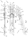
- lever latch 1 comprises, in a per se known manner, a support body 2, preferably made of metal material, which is susceptible of being embedded in a shaped cavity of a leaf (indicated with 100 in figure 12 ), e.g. with external slot form.
- Such support body 2 appears as a box-like body provided with an elongated main extension in a longitudinal direction Y between a first and a second termination, respectively indicated with 2A and 2B, and comprises two lateral walls 3 and 4, parallel to and opposite each other, which delimit, preferably together with a bottom 5, preferably starting from the first termination 2A, a containment chamber 6, which is open at the top in opposite direction with respect to the bottom 5.
- the support body 2 defines a guide 7, which is in communication at a first end with the containment chamber 6 and at the other second end is provided with an outlet opening 70.
- the lever latch 1 also comprises an actuation lever 8, which is hinged to the support body 2 within the containment chamber 6 by means of a first pin 9 arranged along a first transverse axis X and engaged at its ends in opposite seats 10 made on the lateral walls 3, 4 of the support body 2.
- an elongated plate-like spring 11 is provided that is engaged at a first end 11A with a second pin 12 associated with the actuation lever 8 according to a second transverse axis X' parallel to the first transverse axis X of the first pin 9 and arranged in distal position with respect to such first transverse axis X towards the free end of the actuation lever 8.
- the lever latch 1 also consists of a locking rod 13, which is slidably engaged in the guide 7 of the support body 2.
- such locking rod 13 is provided with a first free termination 13A (push rod), possibly tapered, susceptible of being engaged in a hole of a fixed frame or of a floor, and with a second termination 13B fixed to the second end 11B of the elongated plate-like spring 11.
- first free termination 13A push rod
- second termination 13B fixed to the second end 11B of the elongated plate-like spring 11.
- the actuation lever 8 is manually actuatable to rotate around the first pin 9 between a first angular end stop position A, in which the free end 13A of the locking rod 13 projects from the outlet opening 70 of the guide 7, and a second angular end stop position B, in which the locking rod 13 is more retracted in the guide 7, for example having the free end 13A contained in the guide 7 or even only in proximity to the outlet opening 70 of the guide 7.
- the two angular end stop positions A and B are substantially opposite, i.e. they are obtained by rotating the actuation lever 8 by 180 degrees in one sense and in the opposite sense.
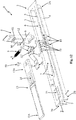
- the actuation lever 8 is contained within the containment chamber 6 on opposite sides with respect to the first pin 9.
- the lateral walls 3, 4 of the support body 2 are provided with a plurality of opposite seats 10 that are aligned along the longitudinal direction Y of the support body 2, and are susceptible of selectively receiving the ends of the first pin 9 in order to vary the position of said actuation lever 8 and of the locking rod 13 along the longitudinal extension direction Y of the support body 2.
- the opposite seats 10 are open at the top, i.e. towards the upper opening of the containment chamber 6 of the support body 2.
- the ends of the first pin 9 can be easily inserted in the pairs of opposite seats 10 starting from the top, i.e. from the exterior of the containment chamber 6 towards its interior, i.e. towards its bottom 5 (if present).
- the elongated plate-like spring 11 is shaped for acting on the first pin 9 so as to elastically force it towards the interior of the seats 10.
- the first pin 9 remains engaged in the respective opposite seats 10 without being able to exit therefrom, if not by following a manual action that overcomes the elastic resistance action of the spring in order to move the first pin 9 into another pair of opposite seats 10.
- the inlet mouth of the opposite seats 10 can be slightly reduced in order to allow the entrance of the ends of the first pin 9 only with an effort aimed to make them go beyond the aforesaid inlet mouth of the pair of opposite seats 10 via elastic deformation. In his manner, the first pin will be stably fixed in its selected position.
- the guide 7 for the locking rod is advantageously in the form of a through channel, which is defined between the lateral walls 3, 4 that are parallel to each other, by the bottom 5 and by an upper wall 71. Both the upper wall 71 and the bottom wall 5 can have one or more windows, respectively indicated with 72 and 52 for an easy molding of the support body 2.
- the guide in through channel form is therefore, for example, open at the top or bottom at such windows 72 and 52 provided at contiguous portions of the support body 2.
- the elongated plate-like spring 11 unloads, on the upper wall of the through channel 71 of the guide 7 and through the locking rod 13, the elastic force adapted to determine the moment that it exerts on the actuation lever 8 for pushing it towards the interior of the containment chamber 6.
- the elongated plate-like spring 11 is shaped with an annular portion 110 placed at its first end 11A, which is wound around the second pin 12.
- annular portion is not circumferentially closed, having a lower opening in order to allow the forced insertion of the second pin 12 at its interior.
- the elongated plate-like spring 11 also comprises, in an intermediate position thereof, a first concave portion 111 directed towards the interior of the containment chamber 6 and susceptible of receiving the first pin 9 of the actuation lever 8 when the latter is in the second angular end stop position B.
- the elongated plate-like spring 11 finally comprises a flattened terminal portion 112 at its second end 11B, which is surmounted on the second termination 13B, also flattened, of the locking rod 13.
- the flattened terminal portion 112 of the elongated plate-like spring 11 and the flattened second termination 13B of the locking rod 13 are fixed to each other by fixing means 50, e.g. screw fixing means, or they are provided with aligned holes engaged for example by a rivet.
- the locking rod 13 can advantageously comprise a window 14, which allows the passage of a fixing screw (not illustrated) for fixing the latch in the seat made in the leaf 100, regarding which in the figures the seat 101 is indicated for the screw on the bottom 5.
- a fixing screw not illustrated
- Such window 14 can also allow forcibly acting with a tool in order to move the locking rod 13 slidably in the guide 7 if the same locking rod 13 is jammed or the actuation lever 8 is unusable.
- the actuation lever 8 comprises two longitudinal shoulders 80 connected to each other by the first and second pins 9, 12, which are longitudinally extended along the extension of the support body 2, parallel to each other.
- the two longitudinal shoulders 80 are also joined by an upper wall 81 opposite the containment chamber 6 and advantageously provided only at the free end of the actuation lever 8 so as to define an opening at the base of the actuation lever 8 at the first pin adapted to allow an improved penetration of the elongated plate-like spring 11 in the actuation lever 8, as better specified hereinbelow.
- the actuation lever 8 is susceptible of receiving, between its two shoulders 80, the terminal section of the elongated plate-like spring 11 towards its first end 11A when it is in the first angular end stop position A. In this manner, the lever latch 1 can maintain the bulk of its thickness extremely limited, allowing limiting the milling operations for the window/shutter/door for making the cavity necessary for housing the support body 2 of the latch 1.
- the elongated plate-like spring 11 comprises, between the annular portion 110 and the first concave portion 111, also a second concave portion 113, in this case with concavity directed towards the exterior of the containment chamber 6.
Landscapes
- Engineering & Computer Science (AREA)
- Structural Engineering (AREA)
- Mechanical Engineering (AREA)
- Lock And Its Accessories (AREA)
- Mechanical Control Devices (AREA)
- Arrangement Or Mounting Of Control Devices For Change-Speed Gearing (AREA)
Claims (10)
- Hebelraste zum Sperren eines Flügels, die Folgendes umfasst:- Einen Trägerkörper (2), der geeignet ist, in eine profilierten Kavität eines Flügels einbettet zu werden und versehen ist, mit:- einem länglichen Hauptverlauf in einer Längsrichtung (Y),- mindestens zwei gegenüberliegenden Seitenwänden (3, 4) die eine an der Oberseite offene Aufnahmekammer (6) begrenzen;- einer an einem ersten Ende mit der genannten Aufnahmekammer (6) verbundenen und an dem anderen zweiten Ende mit einer Austrittsöffnung (70) ausgestatteten Führung (7);- einem Betätigungshebel (8), der an dem genannten Trägerkörper (2) in der genannten Aufnahmekammer (6) mittels eines entlang einer ersten Querachse (X) angeordneten und an seinen Enden in gegenüberliegenden Sitzen (10) an den Außenwänden (3, 4) des genannten Trägerkörpers (2) eingerückten Stifts (9) verankert ist;- einer länglichen, plattenförmigen Feder (11), die an einem ersten Ende (11A) mit einem mechanisch mit dem genannten Betätigungshebel (8) verbundenen zweiten Stift (12) gekuppelt ist, der eine zweite Querachse (X') aufweist und im Verhältnis zu der genannten ersten Querachse (X) in einer distalen Position angeordnet ist;- einer verschiebbar in der Führung (7) des genannten Trägerkörpers (2) gekuppelten Verschlussstange (13), die ausgestattet ist mit:wobei der genannte Betätigungshebel (8) betätigt werden kann, um um den genannten ersten Stift (9) zwischen einer ersten winkligen Endanschlagposition (A), in der der erste freie Abschluss (13A) der genannten Verschlussstange (13) von der Austrittsöffnung (70) der genannten Führung (7) vorsteht, und einer zweiten winkligen Endanschlagposition (B), in der die genannte Verschlussstange (13) weiter in die genannte Führung (7) zurückgezogen ist, zu drehen,- einem ersten freien Abschluss (13A), der geeignet ist, in einer Öffnung eines festen Rahmens oder Bodens in Eingriff gebracht zu werden, und- mit einem an dem zweiten Ende (11B) der genannten länglichen, plattenähnlichen Feder (11) befestigten zweiten Abschluss (13B);
dadurch gekennzeichnet, dass:
die Seitenwände (3, 4) des genannten Trägerkörpers (2) mit einer Vielzahl entlang der Längsrichtung (Y) des genannten Trägerkörpers (2) ausgerichteter gegenüberliegender Sitze (10) versehen und geeignet sind, wahlweise die Enden des genannten ersten Stifts (9) aufzunehmen, um die Position des genannten Betätigungshebels (8) der genannten Verschlussstange (13) entlang der Längsrichtung (Y) des genannten Trägerkörpers (2) zu variieren. - Hebelraste nach Anspruch 1, dadurch gekennzeichnet, dass die genannten gegenüberliegenden Sitze (10) zu der oberen Öffnung der Aufnahmekammer (6) des genannten Trägerkörpers (2) geöffnet sind.
- Hebelraste nach Anspruch 1 oder 2, dadurch gekennzeichnet, dass die genannte längliche, plattenähnliche Feder (11) auf den genannten ersten Stift (9) wirkt und diesen so elastisch zur Innenseite der genannten gegenüberliegenden Sitze (10) treibt.
- Hebelraste nach einem beliebigen der vorangegangenen Ansprüche, dadurch gekennzeichnet, dass die genannte Führung (7) einen durchgehenden Kanal (71) umfasst, der mit einem Eintrittsabschnitt (71A) und mit einem Austrittsabschnitt (71B) ausgestattet ist, der passgenau von der genannten Verschlussstange (8) überquert wird.
- Hebelraste nach Anspruch 3 und 4, dadurch gekennzeichnet, dass die genannte längliche, plattenähnliche Feder (11) auf dem genannten durchgehenden Kanal (71) über die genannte Verschlussstange (13) die Federkraft des auf den genannten Betätigungshebel (8) ausgeübten Moments zum Inneren der genannten Aufnahmekammer (6) entlastet.
- Hebelraste nach einem beliebigen der vorangegangenen Ansprüche, dadurch gekennzeichnet, dass die genannte längliche, plattenähnliche Feder (11) an ihrem ersten Ende (11A) einen um den genannten zweiten Stift (12) gewundenen ringförmigen Abschnitt (110) umfasst.
- Hebelraste nach einem beliebigen der vorangegangenen Ansprüche, dadurch gekennzeichnet, dass die genannte längliche, plattenähnliche Feder (11) in einer Zwischenposition derselben einen zur Innenseite der genannten Aufnahmekammer (6) gerichteten ersten konkaven Abschnitt (111) umfasst, der geeignet ist, den ersten Stift (9) des genannten Betätigungshebels (8) aufzunehmen, wenn Letzterer sich in der genannten zweiten winkligen Endanschlagposition (B) befindet.
- Hebelraste nach einem beliebigen der vorangegangenen Ansprüche, dadurch gekennzeichnet, dass der genannte Betätigungshebel (8) zwei von dem genannten ersten und zweiten Stift (9, 12) verbundene Längsschultern (80) umfasst, die parallel zueinander und quer zur Verlaufsrichtung des genannten Trägerkörpers (2) sind.
- Hebelraste nach Anspruch 6, 7 und 8, dadurch gekennzeichnet, dass die genannte längliche, plattenähnliche Feder (11) zwischen dem genannten ringförmigen Abschnitt (110) und dem genannten ersten konkaven Abschnitt (111) einen zur Außenseite der genannten Aufnahmekammer (6) gerichteten zweiten konkaven Abschnitt (113) umfasst; wobei der genannte Betätigungshebel (8) geeignet ist, den ringförmigen Abschnitt (110) und den ersten konkaven Abschnitt (111) der genannten länglichen, plattenähnlichen Feder (11) aufzunehmen, wenn Letztere sich bei in dem genannten zweiten konkaven Abschnitt (113) untergebrachtem zweiten Stift (12) in der genannten ersten winkligen Endanschlagposition (A) befindet.
- Hebelraste nach Anspruch 1, dadurch gekennzeichnet, dass der genannte Betätigungshebel (8) in der genannten Aufnahmekammer (6) auf gegenüberliegenden Seiten im Verhältnis zu dem genannten ersten Stift (9) in den genannten beiden gegenüberliegenden winkligen Endanschlagpositionen (A, B) enthalten ist.
Priority Applications (1)
| Application Number | Priority Date | Filing Date | Title |
|---|---|---|---|
| PL19156165T PL3524760T3 (pl) | 2018-02-08 | 2019-02-08 | Zatrzask dźwigniowy |
Applications Claiming Priority (1)
| Application Number | Priority Date | Filing Date | Title |
|---|---|---|---|
| IT201800002516A IT201800002516A1 (it) | 2018-02-08 | 2018-02-08 | Catenaccio a leva |
Publications (2)
| Publication Number | Publication Date |
|---|---|
| EP3524760A1 EP3524760A1 (de) | 2019-08-14 |
| EP3524760B1 true EP3524760B1 (de) | 2020-09-30 |
Family
ID=62218127
Family Applications (1)
| Application Number | Title | Priority Date | Filing Date |
|---|---|---|---|
| EP19156165.3A Active EP3524760B1 (de) | 2018-02-08 | 2019-02-08 | Hebelraste |
Country Status (3)
| Country | Link |
|---|---|
| EP (1) | EP3524760B1 (de) |
| IT (1) | IT201800002516A1 (de) |
| PL (1) | PL3524760T3 (de) |
Family Cites Families (5)
| Publication number | Priority date | Publication date | Assignee | Title |
|---|---|---|---|---|
| GB748188A (en) * | 1953-08-27 | 1956-04-25 | Holden & Co B Ham Ltd E | Improvements relating to bolt fastenings |
| US3680901A (en) * | 1970-07-31 | 1972-08-01 | American Metal Climax Inc | Bolt assembly |
| IT1319929B1 (it) * | 2000-03-02 | 2003-11-12 | Master Srl | Catenaccio perfezionato per serramenti. |
| CN102943802B (zh) * | 2012-11-30 | 2014-10-08 | 利亚德光电股份有限公司 | 连接装置、led显示单元及led显示系统 |
| US9145718B1 (en) * | 2014-04-22 | 2015-09-29 | I-Tek Metal Mfg. Co., Ltd. | Latch assembly with an anti-picking function |
-
2018
- 2018-02-08 IT IT201800002516A patent/IT201800002516A1/it unknown
-
2019
- 2019-02-08 PL PL19156165T patent/PL3524760T3/pl unknown
- 2019-02-08 EP EP19156165.3A patent/EP3524760B1/de active Active
Non-Patent Citations (1)
| Title |
|---|
| None * |
Also Published As
| Publication number | Publication date |
|---|---|
| EP3524760A1 (de) | 2019-08-14 |
| IT201800002516A1 (it) | 2019-08-08 |
| PL3524760T3 (pl) | 2021-04-06 |
Similar Documents
| Publication | Publication Date | Title |
|---|---|---|
| US8113607B2 (en) | Storage assembly | |
| US9915093B2 (en) | Security gate | |
| EP2014867A2 (de) | Toranordnung, insbesondere Sicherheitsgitter für Kinder | |
| DE1011772B (de) | Beschlag zum OEffnen und Schliessen der Kipp-Schwenk-Fluegel von Fenstern, Tueren od. dgl. | |
| EP2799656A2 (de) | Gate-Anordnung und Anwendungsverfahren dafür | |
| US20170058579A1 (en) | Locking bolt with surface-mounted transmission | |
| US7963573B2 (en) | Locking device and a method of assembling same | |
| CN102549226A (zh) | 用于可转动窗户处窗户固定装置的控制机构处的装置 | |
| EP3524760B1 (de) | Hebelraste | |
| EP0954667B1 (de) | Schloss mit falle für tür oder fenster | |
| EP2824264B1 (de) | Beschlag für ein Fenster, eine Tür oder dergleichen mit einem kipp- und schiebbaren Flügel | |
| CN108825016B (zh) | 一种防火窗多角度限位机构 | |
| EP1745191A1 (de) | Karusselltür | |
| US8403381B2 (en) | Horse stall door latch | |
| EP3034728B1 (de) | Öffnungsbegrenzereinrichtung | |
| DE69403734T2 (de) | Betätigungseinrichtung für die automatische Verriegelung eines Fensterflügels oder dergleichen | |
| EP3702555B1 (de) | Tür- oder fensteranordnung mit einer antriebseinheit im blendrahmen | |
| EP3183408B1 (de) | Steuerelement für eine beschlaganordnung | |
| DE102008054199B4 (de) | Schloss für Falttore sowie damit versehenes Falttor | |
| IT201900009945A1 (it) | Cerniera a scomparsa regolabile per serramenti | |
| DE102004034375A1 (de) | Gebäudeabschluss-Tor mit Verriegelungsvorrichtung | |
| DE29815650U1 (de) | Seitliche Einfassung für Bordwände von Nutzfahrzeugen mit integriertem Riegelverschluß | |
| DE102007052843B4 (de) | Fallenriegelschloss für eine rahmenlose Glastür | |
| EP3118401A1 (de) | Kantriegel | |
| DE102006000280A1 (de) | Verschluss für einen Treibstangenbeschlag und Treibstangenbeschlag mit einem solchen Verschluss |
Legal Events
| Date | Code | Title | Description |
|---|---|---|---|
| PUAI | Public reference made under article 153(3) epc to a published international application that has entered the european phase |
Free format text: ORIGINAL CODE: 0009012 |
|
| STAA | Information on the status of an ep patent application or granted ep patent |
Free format text: STATUS: THE APPLICATION HAS BEEN PUBLISHED |
|
| AK | Designated contracting states |
Kind code of ref document: A1 Designated state(s): AL AT BE BG CH CY CZ DE DK EE ES FI FR GB GR HR HU IE IS IT LI LT LU LV MC MK MT NL NO PL PT RO RS SE SI SK SM TR |
|
| AX | Request for extension of the european patent |
Extension state: BA ME |
|
| STAA | Information on the status of an ep patent application or granted ep patent |
Free format text: STATUS: REQUEST FOR EXAMINATION WAS MADE |
|
| 17P | Request for examination filed |
Effective date: 20200121 |
|
| RBV | Designated contracting states (corrected) |
Designated state(s): AL AT BE BG CH CY CZ DE DK EE ES FI FR GB GR HR HU IE IS IT LI LT LU LV MC MK MT NL NO PL PT RO RS SE SI SK SM TR |
|
| GRAP | Despatch of communication of intention to grant a patent |
Free format text: ORIGINAL CODE: EPIDOSNIGR1 |
|
| STAA | Information on the status of an ep patent application or granted ep patent |
Free format text: STATUS: GRANT OF PATENT IS INTENDED |
|
| RIC1 | Information provided on ipc code assigned before grant |
Ipc: E05C 1/06 20060101AFI20200430BHEP Ipc: E05B 63/06 20060101ALI20200430BHEP Ipc: E05B 15/04 20060101ALN20200430BHEP |
|
| INTG | Intention to grant announced |
Effective date: 20200518 |
|
| GRAS | Grant fee paid |
Free format text: ORIGINAL CODE: EPIDOSNIGR3 |
|
| GRAA | (expected) grant |
Free format text: ORIGINAL CODE: 0009210 |
|
| STAA | Information on the status of an ep patent application or granted ep patent |
Free format text: STATUS: THE PATENT HAS BEEN GRANTED |
|
| AK | Designated contracting states |
Kind code of ref document: B1 Designated state(s): AL AT BE BG CH CY CZ DE DK EE ES FI FR GB GR HR HU IE IS IT LI LT LU LV MC MK MT NL NO PL PT RO RS SE SI SK SM TR |
|
| REG | Reference to a national code |
Ref country code: CH Ref legal event code: EP Ref country code: GB Ref legal event code: FG4D |
|
| REG | Reference to a national code |
Ref country code: DE Ref legal event code: R096 Ref document number: 602019000797 Country of ref document: DE Ref country code: AT Ref legal event code: REF Ref document number: 1318950 Country of ref document: AT Kind code of ref document: T Effective date: 20201015 |
|
| REG | Reference to a national code |
Ref country code: IE Ref legal event code: FG4D |
|
| PG25 | Lapsed in a contracting state [announced via postgrant information from national office to epo] |
Ref country code: HR Free format text: LAPSE BECAUSE OF FAILURE TO SUBMIT A TRANSLATION OF THE DESCRIPTION OR TO PAY THE FEE WITHIN THE PRESCRIBED TIME-LIMIT Effective date: 20200930 Ref country code: GR Free format text: LAPSE BECAUSE OF FAILURE TO SUBMIT A TRANSLATION OF THE DESCRIPTION OR TO PAY THE FEE WITHIN THE PRESCRIBED TIME-LIMIT Effective date: 20201231 Ref country code: NO Free format text: LAPSE BECAUSE OF FAILURE TO SUBMIT A TRANSLATION OF THE DESCRIPTION OR TO PAY THE FEE WITHIN THE PRESCRIBED TIME-LIMIT Effective date: 20201230 Ref country code: SE Free format text: LAPSE BECAUSE OF FAILURE TO SUBMIT A TRANSLATION OF THE DESCRIPTION OR TO PAY THE FEE WITHIN THE PRESCRIBED TIME-LIMIT Effective date: 20200930 Ref country code: FI Free format text: LAPSE BECAUSE OF FAILURE TO SUBMIT A TRANSLATION OF THE DESCRIPTION OR TO PAY THE FEE WITHIN THE PRESCRIBED TIME-LIMIT Effective date: 20200930 Ref country code: BG Free format text: LAPSE BECAUSE OF FAILURE TO SUBMIT A TRANSLATION OF THE DESCRIPTION OR TO PAY THE FEE WITHIN THE PRESCRIBED TIME-LIMIT Effective date: 20201230 |
|
| REG | Reference to a national code |
Ref country code: AT Ref legal event code: MK05 Ref document number: 1318950 Country of ref document: AT Kind code of ref document: T Effective date: 20200930 |
|
| PG25 | Lapsed in a contracting state [announced via postgrant information from national office to epo] |
Ref country code: LV Free format text: LAPSE BECAUSE OF FAILURE TO SUBMIT A TRANSLATION OF THE DESCRIPTION OR TO PAY THE FEE WITHIN THE PRESCRIBED TIME-LIMIT Effective date: 20200930 Ref country code: RS Free format text: LAPSE BECAUSE OF FAILURE TO SUBMIT A TRANSLATION OF THE DESCRIPTION OR TO PAY THE FEE WITHIN THE PRESCRIBED TIME-LIMIT Effective date: 20200930 |
|
| REG | Reference to a national code |
Ref country code: NL Ref legal event code: MP Effective date: 20200930 |
|
| REG | Reference to a national code |
Ref country code: LT Ref legal event code: MG4D |
|
| PG25 | Lapsed in a contracting state [announced via postgrant information from national office to epo] |
Ref country code: LT Free format text: LAPSE BECAUSE OF FAILURE TO SUBMIT A TRANSLATION OF THE DESCRIPTION OR TO PAY THE FEE WITHIN THE PRESCRIBED TIME-LIMIT Effective date: 20200930 Ref country code: SM Free format text: LAPSE BECAUSE OF FAILURE TO SUBMIT A TRANSLATION OF THE DESCRIPTION OR TO PAY THE FEE WITHIN THE PRESCRIBED TIME-LIMIT Effective date: 20200930 Ref country code: EE Free format text: LAPSE BECAUSE OF FAILURE TO SUBMIT A TRANSLATION OF THE DESCRIPTION OR TO PAY THE FEE WITHIN THE PRESCRIBED TIME-LIMIT Effective date: 20200930 Ref country code: PT Free format text: LAPSE BECAUSE OF FAILURE TO SUBMIT A TRANSLATION OF THE DESCRIPTION OR TO PAY THE FEE WITHIN THE PRESCRIBED TIME-LIMIT Effective date: 20210201 Ref country code: RO Free format text: LAPSE BECAUSE OF FAILURE TO SUBMIT A TRANSLATION OF THE DESCRIPTION OR TO PAY THE FEE WITHIN THE PRESCRIBED TIME-LIMIT Effective date: 20200930 Ref country code: CZ Free format text: LAPSE BECAUSE OF FAILURE TO SUBMIT A TRANSLATION OF THE DESCRIPTION OR TO PAY THE FEE WITHIN THE PRESCRIBED TIME-LIMIT Effective date: 20200930 |
|
| PG25 | Lapsed in a contracting state [announced via postgrant information from national office to epo] |
Ref country code: IS Free format text: LAPSE BECAUSE OF FAILURE TO SUBMIT A TRANSLATION OF THE DESCRIPTION OR TO PAY THE FEE WITHIN THE PRESCRIBED TIME-LIMIT Effective date: 20210130 Ref country code: AT Free format text: LAPSE BECAUSE OF FAILURE TO SUBMIT A TRANSLATION OF THE DESCRIPTION OR TO PAY THE FEE WITHIN THE PRESCRIBED TIME-LIMIT Effective date: 20200930 Ref country code: AL Free format text: LAPSE BECAUSE OF FAILURE TO SUBMIT A TRANSLATION OF THE DESCRIPTION OR TO PAY THE FEE WITHIN THE PRESCRIBED TIME-LIMIT Effective date: 20200930 Ref country code: ES Free format text: LAPSE BECAUSE OF FAILURE TO SUBMIT A TRANSLATION OF THE DESCRIPTION OR TO PAY THE FEE WITHIN THE PRESCRIBED TIME-LIMIT Effective date: 20200930 |
|
| PG25 | Lapsed in a contracting state [announced via postgrant information from national office to epo] |
Ref country code: NL Free format text: LAPSE BECAUSE OF FAILURE TO SUBMIT A TRANSLATION OF THE DESCRIPTION OR TO PAY THE FEE WITHIN THE PRESCRIBED TIME-LIMIT Effective date: 20200930 Ref country code: SK Free format text: LAPSE BECAUSE OF FAILURE TO SUBMIT A TRANSLATION OF THE DESCRIPTION OR TO PAY THE FEE WITHIN THE PRESCRIBED TIME-LIMIT Effective date: 20200930 |
|
| REG | Reference to a national code |
Ref country code: DE Ref legal event code: R097 Ref document number: 602019000797 Country of ref document: DE |
|
| PLBE | No opposition filed within time limit |
Free format text: ORIGINAL CODE: 0009261 |
|
| STAA | Information on the status of an ep patent application or granted ep patent |
Free format text: STATUS: NO OPPOSITION FILED WITHIN TIME LIMIT |
|
| PG25 | Lapsed in a contracting state [announced via postgrant information from national office to epo] |
Ref country code: DK Free format text: LAPSE BECAUSE OF FAILURE TO SUBMIT A TRANSLATION OF THE DESCRIPTION OR TO PAY THE FEE WITHIN THE PRESCRIBED TIME-LIMIT Effective date: 20200930 |
|
| REG | Reference to a national code |
Ref country code: DE Ref legal event code: R119 Ref document number: 602019000797 Country of ref document: DE |
|
| 26N | No opposition filed |
Effective date: 20210701 |
|
| PG25 | Lapsed in a contracting state [announced via postgrant information from national office to epo] |
Ref country code: MC Free format text: LAPSE BECAUSE OF FAILURE TO SUBMIT A TRANSLATION OF THE DESCRIPTION OR TO PAY THE FEE WITHIN THE PRESCRIBED TIME-LIMIT Effective date: 20200930 |
|
| REG | Reference to a national code |
Ref country code: BE Ref legal event code: MM Effective date: 20210228 |
|
| PG25 | Lapsed in a contracting state [announced via postgrant information from national office to epo] |
Ref country code: LU Free format text: LAPSE BECAUSE OF NON-PAYMENT OF DUE FEES Effective date: 20210208 |
|
| PG25 | Lapsed in a contracting state [announced via postgrant information from national office to epo] |
Ref country code: SI Free format text: LAPSE BECAUSE OF FAILURE TO SUBMIT A TRANSLATION OF THE DESCRIPTION OR TO PAY THE FEE WITHIN THE PRESCRIBED TIME-LIMIT Effective date: 20200930 |
|
| PG25 | Lapsed in a contracting state [announced via postgrant information from national office to epo] |
Ref country code: IE Free format text: LAPSE BECAUSE OF NON-PAYMENT OF DUE FEES Effective date: 20210208 Ref country code: DE Free format text: LAPSE BECAUSE OF NON-PAYMENT OF DUE FEES Effective date: 20210901 |
|
| PG25 | Lapsed in a contracting state [announced via postgrant information from national office to epo] |
Ref country code: IS Free format text: LAPSE BECAUSE OF FAILURE TO SUBMIT A TRANSLATION OF THE DESCRIPTION OR TO PAY THE FEE WITHIN THE PRESCRIBED TIME-LIMIT Effective date: 20210130 |
|
| PG25 | Lapsed in a contracting state [announced via postgrant information from national office to epo] |
Ref country code: BE Free format text: LAPSE BECAUSE OF NON-PAYMENT OF DUE FEES Effective date: 20210228 |
|
| REG | Reference to a national code |
Ref country code: CH Ref legal event code: PL |
|
| PG25 | Lapsed in a contracting state [announced via postgrant information from national office to epo] |
Ref country code: LI Free format text: LAPSE BECAUSE OF NON-PAYMENT OF DUE FEES Effective date: 20220228 Ref country code: CH Free format text: LAPSE BECAUSE OF NON-PAYMENT OF DUE FEES Effective date: 20220228 |
|
| P01 | Opt-out of the competence of the unified patent court (upc) registered |
Effective date: 20230302 |
|
| PG25 | Lapsed in a contracting state [announced via postgrant information from national office to epo] |
Ref country code: CY Free format text: LAPSE BECAUSE OF FAILURE TO SUBMIT A TRANSLATION OF THE DESCRIPTION OR TO PAY THE FEE WITHIN THE PRESCRIBED TIME-LIMIT Effective date: 20200930 |
|
| PG25 | Lapsed in a contracting state [announced via postgrant information from national office to epo] |
Ref country code: HU Free format text: LAPSE BECAUSE OF FAILURE TO SUBMIT A TRANSLATION OF THE DESCRIPTION OR TO PAY THE FEE WITHIN THE PRESCRIBED TIME-LIMIT; INVALID AB INITIO Effective date: 20190208 |
|
| GBPC | Gb: european patent ceased through non-payment of renewal fee |
Effective date: 20230208 |
|
| PG25 | Lapsed in a contracting state [announced via postgrant information from national office to epo] |
Ref country code: GB Free format text: LAPSE BECAUSE OF NON-PAYMENT OF DUE FEES Effective date: 20230208 |
|
| PG25 | Lapsed in a contracting state [announced via postgrant information from national office to epo] |
Ref country code: GB Free format text: LAPSE BECAUSE OF NON-PAYMENT OF DUE FEES Effective date: 20230208 |
|
| PG25 | Lapsed in a contracting state [announced via postgrant information from national office to epo] |
Ref country code: MK Free format text: LAPSE BECAUSE OF FAILURE TO SUBMIT A TRANSLATION OF THE DESCRIPTION OR TO PAY THE FEE WITHIN THE PRESCRIBED TIME-LIMIT Effective date: 20200930 |
|
| PG25 | Lapsed in a contracting state [announced via postgrant information from national office to epo] |
Ref country code: TR Free format text: LAPSE BECAUSE OF FAILURE TO SUBMIT A TRANSLATION OF THE DESCRIPTION OR TO PAY THE FEE WITHIN THE PRESCRIBED TIME-LIMIT Effective date: 20200930 |
|
| PG25 | Lapsed in a contracting state [announced via postgrant information from national office to epo] |
Ref country code: MT Free format text: LAPSE BECAUSE OF FAILURE TO SUBMIT A TRANSLATION OF THE DESCRIPTION OR TO PAY THE FEE WITHIN THE PRESCRIBED TIME-LIMIT Effective date: 20200930 |
|
| PGFP | Annual fee paid to national office [announced via postgrant information from national office to epo] |
Ref country code: PL Payment date: 20250128 Year of fee payment: 7 Ref country code: FR Payment date: 20250224 Year of fee payment: 7 |
|
| PGFP | Annual fee paid to national office [announced via postgrant information from national office to epo] |
Ref country code: IT Payment date: 20250124 Year of fee payment: 7 |