EP3524807A1 - Dispositifs comprenant un moteur à turbine à gaz et un éjecteur - Google Patents
Dispositifs comprenant un moteur à turbine à gaz et un éjecteur Download PDFInfo
- Publication number
- EP3524807A1 EP3524807A1 EP19157332.8A EP19157332A EP3524807A1 EP 3524807 A1 EP3524807 A1 EP 3524807A1 EP 19157332 A EP19157332 A EP 19157332A EP 3524807 A1 EP3524807 A1 EP 3524807A1
- Authority
- EP
- European Patent Office
- Prior art keywords
- boundary layer
- gas turbine
- flow
- ejector
- turbine engine
- Prior art date
- Legal status (The legal status is an assumption and is not a legal conclusion. Google has not performed a legal analysis and makes no representation as to the accuracy of the status listed.)
- Granted
Links
Images


Classifications
-
- F—MECHANICAL ENGINEERING; LIGHTING; HEATING; WEAPONS; BLASTING
- F02—COMBUSTION ENGINES; HOT-GAS OR COMBUSTION-PRODUCT ENGINE PLANTS
- F02K—JET-PROPULSION PLANTS
- F02K3/00—Plants including a gas turbine driving a compressor or a ducted fan
- F02K3/02—Plants including a gas turbine driving a compressor or a ducted fan in which part of the working fluid by-passes the turbine and combustion chamber
- F02K3/04—Plants including a gas turbine driving a compressor or a ducted fan in which part of the working fluid by-passes the turbine and combustion chamber the plant including ducted fans, i.e. fans with high volume, low pressure outputs, for augmenting the jet thrust, e.g. of double-flow type
- F02K3/077—Plants including a gas turbine driving a compressor or a ducted fan in which part of the working fluid by-passes the turbine and combustion chamber the plant including ducted fans, i.e. fans with high volume, low pressure outputs, for augmenting the jet thrust, e.g. of double-flow type the plant being of the multiple flow type, i.e. having three or more flows
-
- B—PERFORMING OPERATIONS; TRANSPORTING
- B64—AIRCRAFT; AVIATION; COSMONAUTICS
- B64C—AEROPLANES; HELICOPTERS
- B64C7/00—Structures or fairings not otherwise provided for
- B64C7/02—Nacelles
-
- F—MECHANICAL ENGINEERING; LIGHTING; HEATING; WEAPONS; BLASTING
- F02—COMBUSTION ENGINES; HOT-GAS OR COMBUSTION-PRODUCT ENGINE PLANTS
- F02K—JET-PROPULSION PLANTS
- F02K1/00—Plants characterised by the form or arrangement of the jet pipe or nozzle; Jet pipes or nozzles peculiar thereto
- F02K1/36—Plants characterised by the form or arrangement of the jet pipe or nozzle; Jet pipes or nozzles peculiar thereto having an ejector
-
- F—MECHANICAL ENGINEERING; LIGHTING; HEATING; WEAPONS; BLASTING
- F02—COMBUSTION ENGINES; HOT-GAS OR COMBUSTION-PRODUCT ENGINE PLANTS
- F02K—JET-PROPULSION PLANTS
- F02K3/00—Plants including a gas turbine driving a compressor or a ducted fan
- F02K3/02—Plants including a gas turbine driving a compressor or a ducted fan in which part of the working fluid by-passes the turbine and combustion chamber
- F02K3/025—Plants including a gas turbine driving a compressor or a ducted fan in which part of the working fluid by-passes the turbine and combustion chamber the by-pass flow being at least partly used to create an independent thrust component
-
- F—MECHANICAL ENGINEERING; LIGHTING; HEATING; WEAPONS; BLASTING
- F02—COMBUSTION ENGINES; HOT-GAS OR COMBUSTION-PRODUCT ENGINE PLANTS
- F02K—JET-PROPULSION PLANTS
- F02K3/00—Plants including a gas turbine driving a compressor or a ducted fan
- F02K3/02—Plants including a gas turbine driving a compressor or a ducted fan in which part of the working fluid by-passes the turbine and combustion chamber
- F02K3/04—Plants including a gas turbine driving a compressor or a ducted fan in which part of the working fluid by-passes the turbine and combustion chamber the plant including ducted fans, i.e. fans with high volume, low pressure outputs, for augmenting the jet thrust, e.g. of double-flow type
- F02K3/075—Plants including a gas turbine driving a compressor or a ducted fan in which part of the working fluid by-passes the turbine and combustion chamber the plant including ducted fans, i.e. fans with high volume, low pressure outputs, for augmenting the jet thrust, e.g. of double-flow type controlling flow ratio between flows
-
- B—PERFORMING OPERATIONS; TRANSPORTING
- B64—AIRCRAFT; AVIATION; COSMONAUTICS
- B64D—EQUIPMENT FOR FITTING IN OR TO AIRCRAFT; FLIGHT SUITS; PARACHUTES; ARRANGEMENT OR MOUNTING OF POWER PLANTS OR PROPULSION TRANSMISSIONS IN AIRCRAFT
- B64D33/00—Arrangement in aircraft of power plant parts or auxiliaries not otherwise provided for
- B64D33/02—Arrangement in aircraft of power plant parts or auxiliaries not otherwise provided for of combustion air intakes
- B64D2033/0226—Arrangement in aircraft of power plant parts or auxiliaries not otherwise provided for of combustion air intakes comprising boundary layer control means
-
- F—MECHANICAL ENGINEERING; LIGHTING; HEATING; WEAPONS; BLASTING
- F05—INDEXING SCHEMES RELATING TO ENGINES OR PUMPS IN VARIOUS SUBCLASSES OF CLASSES F01-F04
- F05D—INDEXING SCHEME FOR ASPECTS RELATING TO NON-POSITIVE-DISPLACEMENT MACHINES OR ENGINES, GAS-TURBINES OR JET-PROPULSION PLANTS
- F05D2260/00—Function
- F05D2260/60—Fluid transfer
- F05D2260/601—Fluid transfer using an ejector or a jet pump
-
- F—MECHANICAL ENGINEERING; LIGHTING; HEATING; WEAPONS; BLASTING
- F05—INDEXING SCHEMES RELATING TO ENGINES OR PUMPS IN VARIOUS SUBCLASSES OF CLASSES F01-F04
- F05D—INDEXING SCHEME FOR ASPECTS RELATING TO NON-POSITIVE-DISPLACEMENT MACHINES OR ENGINES, GAS-TURBINES OR JET-PROPULSION PLANTS
- F05D2270/00—Control
- F05D2270/01—Purpose of the control system
- F05D2270/17—Purpose of the control system to control boundary layer
Definitions
- the present invention generally relates to gas turbine engines useful in removing a boundary layer of air, and more particularly, but not exclusively, to integrated aircraft engine with an ejector having fluid supplied by boundary layer bleed flow.
- the present inventions address problems associated with existing propulsion systems by providing a novel and non-obvious contributions relating thereto.
- One embodiment of the present invention is a unique gas turbine engine ejector for removing a boundary layer from a flow surface.
- Other embodiments include apparatuses, systems, devices, hardware, methods, and combinations for removing a boundary layer through an ejector action. Further embodiments, forms, features, aspects, benefits, and advantages of the present application shall become apparent from the description and figures provided herewith.
- the present inventions include a boundary layer ejector fluidically connecting boundary layer bleed slots from an external surface of an aircraft/nacelle/pylon to reduce aircraft drag, reduce jet noise and decrease thrust specific fuel consumption.
- One aspect of the present invention relates to a propulsion nozzle ejector utilizing boundary layer bleed to supply airflow to an ejector passageway.
- the disclosed ejector is operable to increase take-off thrust, reduce in-flight thrust specific fuel consumption, reduce installation and aircraft drag, reduce in-flight jet noise through a decrease in exhaust velocity, and provide a source of relatively low temperature airflow for thermal management of aircraft systems.
- Boundary layer fluid flow is defined by the fluid in a layer adjacent to a body within which the major effects of viscosity are concentrated.
- viscosity can be thought of as the thickness of the low velocity fluid or the resistance of the fluid to flow along a pathway.
- Viscous fluids create a boundary layer adjacent a body wherein the velocity of the fluid is approximately zero at the surface of the body and increases proportionally until it reaches the bulk fluid velocity outside of the boundary layer.
- the boundary layer produces losses due to aerodynamic drag on the aircraft.
- the boundary layer can be thought of as a dead zone wherein minimal useful fluid work can be done.
- the present invention advantageously removes at least a portion of boundary layer fluid and converts the boundary layer fluid into a useful means of increasing system efficiency and providing a source of thermal management.
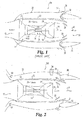
- gas turbine engine 10A a prior art gas turbine engine 10A is illustrated. Components of the prior art engine 10A that are similar to the inventive engine 10B in FIG. 2 , will have the same numerical description.
- the gas turbine engine 10A, as well as the inventive engine 10B, can take a variety of forms and in application can be used to provide power to an aircraft.
- the gas turbine engine 10A and/or 10B can be an adaptive cycle engine or a variable cycle engine.
- the gas turbine engine 10A and/or 10B can have any number of spools, including just one.
- the gas turbine engine 10A and/or 10B can be a turbojet, turboprop, turbofan, or a turboshaft engine.
- aircraft includes, but is not limited to, helicopters, airplanes, unmanned space vehicles, fixed wing vehicles, variable wing vehicles, rotary wing vehicles, unmanned combat aerial vehicles, tailless aircraft, hover crafts, and other airborne and/or extraterrestrial (spacecraft) vehicles.
- helicopters airplanes
- unmanned space vehicles fixed wing vehicles
- variable wing vehicles variable wing vehicles
- rotary wing vehicles unmanned combat aerial vehicles
- tailless aircraft hover crafts
- other airborne and/or extraterrestrial (spacecraft) vehicles include, for example, industrial applications, power generation, pumping sets, naval propulsion, weapon systems, security systems, perimeter defense/security systems, and the like known to one of ordinary skill in the art.
- the gas turbine engine 10A of the illustrative embodiment includes an inlet section 12, a compression section 14, a combustion section 16, an expansion or turbine section 18, and an exhaust section 20.
- air is drawn in through the inlet 12 and compressed to a high pressure relative to ambient pressure in the compression section 14.
- the air is mixed with fuel in the combustion section 16 wherein the fuel/air mixture burns and produces a high temperature and pressure working fluid from which the turbine section 18 extracts power.
- the turbine section 18 is mechanically coupled to the compression section 14 via a shaft 21.
- the shaft 21 rotates about a centerline axis that extends axially along the longitudinal axis of the engine 10A, such that as the turbine section 18 rotates due to the forces generated by the high pressure working fluid the compression section 14 is rotatingly driven by the turbine section 18 to produce compressed air.
- the compression section 14 can optionally include a low-pressure fan 23 which produces a bypass flow stream represented by arrow 26.
- the bypass flow stream 26 flows between an outer case 22 and an inner faring 24 that encompasses the core 25 of the engine 10A.
- the core 25 produces a core exhaust flow represented by arrow 28.
- Mixed engine exhaust flow represented by arrows 30 is the combined mass flow of the bypass flow 26 and the core flow 28.
- a nacelle 32 encompasses the outer case 22 of the engine 10A.
- a variable flap 34 is positioned adjacent the aft end of the nacelle 32. In other embodiments, however, the variable flap 34 can be located at positions other than adjacent the aft end of the nacelle 32.
- a nozzle 36 is positioned further aft of the variable flap 34 in the illustrative embodiment.
- a nozzle ejector flow 38 can be entrained through a passageway 39 formed between the variable flap 34 and the nozzle 36.
- the passageway 39 can be formed between the variable flap 34 and a structure or structures other than the nozzle 36.
- a total exhaust flow represented by arrow 40 includes the mixed engine exhaust flow 30 and the nozzle ejector flow 38.
- the gas turbine engine 10B includes boundary layer bleed flow represented by arrow 50.
- the boundary layer bleed flow 50 can be transported through bleed ports (not shown in FIG. 2 but described and shown further below) from any surface of the engine 10B or aircraft (also not shown in FIG. 2 but described and shown further below) and directed through a nacelle passageway 52.
- the bleed ports can take any variety of forms including slots or holes, among potential others. As a matter of convenience of description, therefore, the term "bleed port" can refer to any of these types of configurations.
- the surface from which the boundary layer bleed flow 50 originates from can be any surface which is exposed to a moving fluid. Such surfaces include the outside portion of a nacelle exposed to the free stream, the inside surface forming part of the passageway through which the bypass flow stream passes, among potential other surfaces.
- one or more heat exchangers 54 can be disposed within the passageway 52 to remove heat from system components (not shown).
- the one or more heat exchangers 54 can take a variety of forms and, in those applications in which multiple heat exchanges 54 are used, not all need be the same.
- the temperature of the boundary layer bleed flow 50 can be approximately the same as the ambient temperature, therefore at altitude the boundary layer bleed flow 50 can provide a large heatsink.
- the flow can be accelerated through a channel 51 between the nozzle 36 and the outer case 22.
- the channel 51 can be of an orientation to permit the flow to be accelerated.
- the channel 51 can have a smaller cross sectional area relative to the passageway 52 at locations upstream of the channel 51.
- a channel member 53 can be used to selectively vary the cross sectional area of the channel 51, and in particular can be used to change the exit area of the passageway 52.
- the channel member 53 can be actuated at a variety of rates which can depend on properties of a total exhaust flow 56 which is the boundary layer bleed flow 50 mixed with the bypass flow 26 and the core flow 28. Removing boundary layer flow from external surfaces reduces the drag and the additional mass flow added into the total exhaust flow 56 increases the thrust of the engine 10B.
- variable flap 34 In the takeoff and taxi mode the variable flap 34 can be opened as shown in the dashed outline which permits air to enter from the rear and go around the ejector leading edge into the exhaust stream 56, similar to that depicted in Fig. 1 .
- the integrated static pressure around the ejector results in a thrust component while the jet noise is reduced as a result of reduced exhaust velocity.
- the variable flap 34 In cruise mode, the variable flap 34 can be closed as depicted by the solid outline in FIG. 2 .
- Boundary layer bleed air 50 is then pulled from passageways connected to a surface associated with any of the nacelle, pylon, wing, or fuselage or other locations that a boundary layer can build up on. The resulting removal of the boundary layer reduces the installation/aircraft drag.
- the RAM effect during cruise in conjunction with ejector pumping can effectively remove the boundary layer especially since the ejector is being driven by a high velocity (normally sonic but can be supersonic) and high mass flow primary nozzle 36 which will entrain a large amount of secondary flow.
- Ejector pumping can be further enhanced by forming the shroud, concentric surface, or other structure that separates the primary nozzle flow from the secondary boundary layer flow as a lobed mixer configuration. Such a configuration can assist in forcing mixing between the two flows and permit shortening of the engine length.
- a nacelle 70 can include boundary layer bleed ports 72 fluidically connected to a member 74 or the like extending at least partially across the flow path depicted.
- the member 74 can take the form of a strut, an outlet guide vane, or other type of member disposed within the flow path.
- the member includes a passage 75 through which a boundary layer which has been pulled through boundary layer bleed ports 72 can pass.
- the passage 75 can be the hollow interior of the member 74, but can also take other forms in different embodiments.
- the passage 75 can extend across the bypass flow path 77 and the core flow path 79.
- the member 74 can include one or more exit apertures 81 through which the boundary layer which has been pulled through boundary layer bleed ports 72 can pass after passing through the passage 75.
- the one or more exit apertures 81 can be formed in or near the trailing edge of the member 74.
- a conduit 76 can be provided in a member 74 which is operable to carry relatively cool boundary layer bleed air 78 to one or more components 80 within the engine 10C requiring cooling flow.
- the component 80 can be an electronic apparatus or a relatively hot mechanical apparatus such as a combustion or turbine component.
- conduit 76 is depicted in a member 74 downstream of the member 74 having the exit apertures 81, it will be appreciated that the conduit 76 can be provided in the member 74 shown as having the apertures 81, but in an embodiment that otherwise lacks the apertures 81. In other words, in lieu of or in addition to the aperture 81, the member 74 can include the conduit 76. In still further embodiments the conduit 76 can lead to an ejector such as the nozzle ejector depicted in the embodiments of Fig. 2 .
- the alternate engine configuration 10C can be used to remove a boundary layer through boundary layer bleed ports 72 to increase inlet pressure recovery and reduce pressure distortion seen by the fan.
- the resulting higher pressure recovery increases thrust and lowers specific fuel consumption.
- the lower pressure distortion increases stall margin.
- the engine 10C can include a flow path protrusion 83 that can reduce the cross sectional area of the bypass flow path 77 at that location.
- a flow path protrusion 83 that can reduce the cross sectional area of the bypass flow path 77 at that location.
- outlet guide vanes OGV's
- the inner and outer walls of the OGV's can be tapered to reduce the area increase thus increasing the OGV exit velocity and ejector pumping.
- the flow path protrusion 83 can be used to locally lower the pressure of the fluid passing through the bypass flow path 77 so that in the case of boundary layer which has been pulled through boundary layer bleed ports 72 and is discharged through the exit aperture 81 can be entrained by the flow through the bypass flow path 77.
- the flow path protrusion 83 can be actuated and moved to a variety of positions to selectively lower or raise the local pressure and thus vary the ability of the flow through the bypass flow path 77 to entrain the boundary layer which has been pulled through boundary layer bleed ports 72.
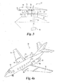
- an aircraft 90 having a fuselage 92 with wings 94 extending therefrom and gas turbine engines 96 mounted thereon.
- the wings 94 can include a plurality of bleed slots 98 for removing boundary layer flow from the wings 94 and delivering said flow to the ejector nozzle or other components disposed on the aircraft 90, such as through any of the various embodiments discussed herein.
- nacelle bleed slots 100 and fuselage bleed slots 102 can be utilized for removing boundary layer flow.
- the Mach number in the passage located between the nacelle 146 and the fuselage 148 could increase because of the blockage created by the boundary layer thus resulting in increased installation drag. Removal of this boundary layer through one or more of the bleed slots 144 depicted in Fig. 4d can result in decreased drag.
- the bleed slots 144 can be located on either or both of the fuselage 148 or nacelle 146.
- an alternate aircraft configuration 110 is depicted with wing 114 mounted engines 116. Similar to the aircraft of FIG. 4a the fuselage 112, the wings 114, and the engines 116 can all include boundary layer bleed slots 118, 120 and 122 respectively.
- FIG 4c illustrates a military style aircraft 130 wherein the engines 136 are embedded within a fuselage 132.
- the fuselage 132, a nacelle 141 surrounding the engine 136 and the wings 134 can all include boundary layer bleed slots 142, 140, and 138 respectively.
- the slots can also be located between the inlet and the fuselage (sometimes referred to as the "arm pit") where the fuselage boundary layer can thicken.
- boundary layer bleed slots can be positioned anywhere on the aircraft and/or engine and are not limited by the examples disclosed in the present application. Any type of aircraft or spacecraft that can advantageously use the teachings of this disclosure is contemplated by the present invention.
- the present invention provides an apparatus comprising an aircraft having a fuselage, wings and an aircraft engine, a nacelle at least partially surrounding the aircraft engine and connected to the aircraft, an airflow passageway formed proximate the nacelle fluidically connected to a plurality of apertures formed on at least a portion of the aircraft, wherein the apertures are operable to remove boundary layer air adjacent an outer surface of the aircraft.
- the present invention further provides a heat exchanger positioned within the passageway.
- the boundary layer air is at least partially drawn into the passageway by an ejector nozzle.
- boundary layer air is at least partially drawn into the passageway by RAM effect.
- the present application provides an apparatus comprising a gas turbine engine capable of producing an exhaust flow, a nozzle structured to convey the exhaust flow from the gas turbine engine, an airflow surface having a boundary layer of moving fluid when a working fluid is flowed along the airflow surface, a conduit disposed between the nozzle and the airflow surface, and a nozzle ejector operable to extract at least a portion of the boundary layer through the conduit and entrain the at least a portion of the boundary layer with the exhaust flow.
- the present application provides an apparatus comprising a gas turbine engine having a rotatable blade operable to produce a flow stream through a flow passage, a surface along which a working fluid can pass and having an opening through which at least a portion of a boundary layer of the working fluid can be withdrawn, and an airflow member extending across the flow passage and having a conduit through which the boundary layer withdrawn from the surface can pass.
- the present application provides an apparatus comprising a gas turbine engine having a nozzle ejector, an exhaust flow from the gas turbine engine forming the primary fluid of the nozzle ejector, a passageway operable to convey at least a portion of a boundary layer air withdrawn from a flow stream surface upstream of the nozzle ejector, and a moveable ejector selector having an open position and a closed position, the open position forming an open position secondary airflow path from an exterior location of the nozzle ejector to the primary fluid of the nozzle ejector, the closed position forming a closed position secondary airflow path from the flow stream surface, through the passageway, and to the primary fluid of the nozzle ejector.
- the present application provides a method comprising operating a gas turbine engine to produce an exhaust flow, withdrawing a boundary layer air from a working fluid flowing along an airflow surface, and entraining the boundary layer air with the exhaust flow using a nozzle ejector of the gas turbine engine.
Landscapes
- Engineering & Computer Science (AREA)
- Chemical & Material Sciences (AREA)
- Combustion & Propulsion (AREA)
- Mechanical Engineering (AREA)
- General Engineering & Computer Science (AREA)
- Aviation & Aerospace Engineering (AREA)
- Jet Pumps And Other Pumps (AREA)
- Structures Of Non-Positive Displacement Pumps (AREA)
Applications Claiming Priority (3)
| Application Number | Priority Date | Filing Date | Title |
|---|---|---|---|
| US20400408P | 2008-12-31 | 2008-12-31 | |
| US12/604,759 US8572947B2 (en) | 2008-12-31 | 2009-10-23 | Gas turbine engine with ejector |
| EP09015974.0A EP2204568B1 (fr) | 2008-12-31 | 2009-12-23 | Moteur à turbine à gaz avec éjecteur et procédé d'exploitation associé |
Related Parent Applications (1)
| Application Number | Title | Priority Date | Filing Date |
|---|---|---|---|
| EP09015974.0A Division EP2204568B1 (fr) | 2008-12-31 | 2009-12-23 | Moteur à turbine à gaz avec éjecteur et procédé d'exploitation associé |
Publications (2)
| Publication Number | Publication Date |
|---|---|
| EP3524807A1 true EP3524807A1 (fr) | 2019-08-14 |
| EP3524807B1 EP3524807B1 (fr) | 2020-11-04 |
Family
ID=41692990
Family Applications (2)
| Application Number | Title | Priority Date | Filing Date |
|---|---|---|---|
| EP09015974.0A Active EP2204568B1 (fr) | 2008-12-31 | 2009-12-23 | Moteur à turbine à gaz avec éjecteur et procédé d'exploitation associé |
| EP19157332.8A Active EP3524807B1 (fr) | 2008-12-31 | 2009-12-23 | Dispositif comprenant un moteur à turbine à gaz et un éjecteur |
Family Applications Before (1)
| Application Number | Title | Priority Date | Filing Date |
|---|---|---|---|
| EP09015974.0A Active EP2204568B1 (fr) | 2008-12-31 | 2009-12-23 | Moteur à turbine à gaz avec éjecteur et procédé d'exploitation associé |
Country Status (3)
| Country | Link |
|---|---|
| US (1) | US8572947B2 (fr) |
| EP (2) | EP2204568B1 (fr) |
| CA (1) | CA2689176C (fr) |
Families Citing this family (20)
| Publication number | Priority date | Publication date | Assignee | Title |
|---|---|---|---|---|
| US8572947B2 (en) | 2008-12-31 | 2013-11-05 | Rolls-Royce Corporation | Gas turbine engine with ejector |
| WO2012018615A1 (fr) | 2010-07-26 | 2012-02-09 | Rolls-Royce Corporation | Turbine à gaz comprenant un éjecteur |
| WO2013077924A2 (fr) * | 2011-09-08 | 2013-05-30 | Rolls-Royce North American Technologies Inc. | Système de moteur à turbine à gaz et tuyère d'éjection supersonique |
| US9630706B2 (en) | 2013-02-22 | 2017-04-25 | Rolls-Royce Corporation | Positionable ejector member for ejector enhanced boundary layer alleviation |
| GB201412189D0 (en) * | 2014-07-09 | 2014-08-20 | Rolls Royce Plc | A nozzle arrangement for a gas turbine engine |
| USD868627S1 (en) | 2018-04-27 | 2019-12-03 | Jetoptera, Inc. | Flying car |
| US10464668B2 (en) | 2015-09-02 | 2019-11-05 | Jetoptera, Inc. | Configuration for vertical take-off and landing system for aerial vehicles |
| KR102668106B1 (ko) | 2015-09-02 | 2024-05-22 | 제톱테라 잉크. | 이젝터 및 에어포일 구조체 |
| US11001378B2 (en) | 2016-08-08 | 2021-05-11 | Jetoptera, Inc. | Configuration for vertical take-off and landing system for aerial vehicles |
| US10174665B2 (en) | 2016-03-18 | 2019-01-08 | Pratt & Whitney Canada Corp. | Active control flow system and method of cooling and providing active flow control |
| MY203613A (en) | 2017-06-27 | 2024-07-10 | Jetoptera Inc | Configuration for vertical take-off and landing system for aerial vehicles |
| CN109720586A (zh) * | 2017-10-30 | 2019-05-07 | 成都飞机工业(集团)有限责任公司 | 一种附面层隔道 |
| KR102103794B1 (ko) * | 2018-06-22 | 2020-05-29 | 한국항공우주산업 주식회사 | 멀티엔진을 갖는 항공기의 자연환기구조 |
| US11313276B2 (en) | 2019-08-01 | 2022-04-26 | Rolls-Royce Deutschland Ltd & Co Kg | Supersonic gas turbine engine |
| FR3107563A1 (fr) * | 2020-02-25 | 2021-08-27 | Airbus Operations | Ensemble propulsif pour aeronef comportant un systeme de ventilation |
| CN111911438B (zh) * | 2020-09-24 | 2021-11-19 | 江西艾斯欧匹精密智造科技有限公司 | 一种便于拆装的高散热风机 |
| US12441475B2 (en) * | 2020-10-30 | 2025-10-14 | Rtx Corporation | Gas turbine engine mounted above wing and with camber |
| CN113788151B (zh) * | 2021-08-26 | 2024-07-12 | 厦门大学 | 一种基于宏观孔隙结构的高超声速进气道强制转捩方法 |
| US12162618B2 (en) | 2021-10-11 | 2024-12-10 | Boom Technology, Inc. | Dissimilarly shaped aircraft nozzles with tandem mixing devices, and associated systems and methods |
| GB2610451B (en) * | 2022-01-18 | 2024-01-03 | Lynley Ashley Adrian | Turbofan engine efficient ducting |
Citations (4)
| Publication number | Priority date | Publication date | Assignee | Title |
|---|---|---|---|---|
| US3317162A (en) * | 1965-07-13 | 1967-05-02 | Charles H Grant | Aircraft wing with internal air passages for increased lift |
| US3409228A (en) * | 1966-02-10 | 1968-11-05 | Gen Electric | Ejector nozzle |
| US4052847A (en) * | 1975-02-14 | 1977-10-11 | Rolls-Royce Limited | Gas turbine engine gas flow ducts |
| US5586431A (en) * | 1994-12-06 | 1996-12-24 | United Technologies Corporation | Aircraft nacelle ventilation and engine exhaust nozzle cooling |
Family Cites Families (44)
| Publication number | Priority date | Publication date | Assignee | Title |
|---|---|---|---|---|
| US2972860A (en) | 1958-01-30 | 1961-02-28 | Westinghouse Electric Corp | Combined variable ejector and thrust reverser |
| FR1496091A (fr) | 1966-04-20 | 1967-09-29 | Snecma | Tuyère d'éjection pour propulseurs à plusieurs flux moteurs, notamment à deux flux moteurs |
| US3572960A (en) | 1969-01-02 | 1971-03-30 | Gen Electric | Reduction of sound in gas turbine engines |
| US3591087A (en) | 1969-05-08 | 1971-07-06 | Rohr Corp | Apparatus for augmenting the thrust of an aircraft jet engine |
| US3591085A (en) | 1969-07-02 | 1971-07-06 | Rohr Corp | Sound suppressing and thrust reversing apparatus |
| US3710890A (en) | 1971-09-27 | 1973-01-16 | Boeing Co | Aircraft engine noise suppression |
| US4043121A (en) * | 1975-01-02 | 1977-08-23 | General Electric Company | Two-spool variable cycle engine |
| US4018046A (en) | 1975-07-17 | 1977-04-19 | Avco Corporation | Infrared radiation suppressor for gas turbine engine |
| GB1545365A (en) | 1977-02-24 | 1979-05-10 | Rolls Royce | Gas turbine engines |
| US4295332A (en) | 1978-11-13 | 1981-10-20 | General Electric Company | Infrared suppressor system |
| US4466587A (en) | 1981-12-21 | 1984-08-21 | General Electric Company | Nacelle installation |
| US5746047A (en) | 1982-07-08 | 1998-05-05 | Gereral Electric Company | Infrared suppressor |
| US4493184A (en) | 1983-03-07 | 1985-01-15 | United Technologies Corporation | Pressurized nacelle compartment for active clearance controlled gas turbine engines |
| US5136837A (en) | 1990-03-06 | 1992-08-11 | General Electric Company | Aircraft engine starter integrated boundary bleed system |
| US5284012A (en) | 1991-05-16 | 1994-02-08 | General Electric Company | Nacelle cooling and ventilation system |
| US5137230A (en) * | 1991-06-04 | 1992-08-11 | General Electric Company | Aircraft gas turbine engine bleed air energy recovery apparatus |
| US5435127A (en) | 1993-11-15 | 1995-07-25 | General Electric Company | Method and apparatus for boosting ram airflow to an ejection nozzle |
| FR2734320B1 (fr) | 1995-05-15 | 1997-07-18 | Aerospatiale | Dispositif pour prelever et refroidir de l'air chaud au niveau d'un moteur d'aeronef |
| US6301877B1 (en) | 1995-11-13 | 2001-10-16 | United Technologies Corporation | Ejector extension cooling for exhaust nozzle |
| DE19617952C2 (de) | 1996-05-04 | 1998-07-02 | Daimler Benz Aerospace Airbus | Absauggeneratorsystem eines Flugzeuges für die Laminarhaltung der Grenzschicht |
| US6094907A (en) | 1996-06-05 | 2000-08-01 | The Boeing Company | Jet engine and method for reducing jet engine noise by reducing nacelle boundary layer thickness |
| US5941065A (en) | 1996-11-04 | 1999-08-24 | The Boeing Company | Stowable mixer ejection nozzle |
| DE19820097C2 (de) | 1998-05-06 | 2003-02-13 | Airbus Gmbh | Anordnung zur Grenzschichtabsaugung und Stoßgrenzschichtkontrolle für ein Flugzeug |
| JP4011829B2 (ja) * | 2000-06-14 | 2007-11-21 | キヤノン株式会社 | 撮像装置及びその制御方法 |
| US6295805B1 (en) | 2000-09-14 | 2001-10-02 | Lockheed Martin Corporation | Exhaust induced ejector nozzle system and method |
| US20020092948A1 (en) | 2001-01-16 | 2002-07-18 | Dugan John J. | Apparatus and method for reducing jet engine noise |
| US6651929B2 (en) | 2001-10-29 | 2003-11-25 | Pratt & Whitney Canada Corp. | Passive cooling system for auxiliary power unit installation |
| US7143983B2 (en) | 2002-08-28 | 2006-12-05 | Lockheed Martin Corporation | Passive jet spoiler for yaw control of an aircraft |
| GB2402196B (en) | 2003-05-29 | 2006-05-17 | Rolls Royce Plc | A laminar flow nacelle for an aircraft engine |
| GB2407142B (en) | 2003-10-15 | 2006-03-01 | Rolls Royce Plc | An arrangement for bleeding the boundary layer from an aircraft engine |
| US6983602B2 (en) | 2004-04-21 | 2006-01-10 | General Electric Company | Ejector cooled nozzle |
| US6988674B2 (en) | 2004-06-08 | 2006-01-24 | General Electric Company | Method and apparatus for suppressing infrared signatures |
| US7980054B2 (en) | 2004-12-01 | 2011-07-19 | United Technologies Corporation | Ejector cooling of outer case for tip turbine engine |
| US7424805B2 (en) | 2005-04-29 | 2008-09-16 | General Electric Company | Supersonic missile turbojet engine |
| US7607305B2 (en) | 2005-08-03 | 2009-10-27 | General Electric Company | One-piece baffle infrared suppressor apparatus and method |
| US7607306B2 (en) | 2005-08-03 | 2009-10-27 | General Electric Company | Infrared suppressor apparatus and method |
| GB2437295B (en) | 2006-04-20 | 2008-06-25 | Rolls Royce Plc | Aeroengine ventilation system |
| US7770381B2 (en) * | 2006-12-18 | 2010-08-10 | General Electric Company | Duct burning mixed flow turbofan and method of operation |
| US7766280B2 (en) | 2007-05-29 | 2010-08-03 | United Technologies Corporation | Integral suction device with acoustic panel |
| US8192147B2 (en) | 2007-12-14 | 2012-06-05 | United Technologies Corporation | Nacelle assembly having inlet bleed |
| EP2075194B1 (fr) | 2007-12-27 | 2017-08-16 | Techspace Aero | Echangeur de chaleur air-huile pour turboréacteur, turboréacteur associé et utilisation dudit échangeur |
| US20090217643A1 (en) | 2008-02-29 | 2009-09-03 | Sokhey Jagdish S | Gas discharge device for a vehicle engine |
| DE102008028987A1 (de) | 2008-06-20 | 2009-12-24 | Rolls-Royce Deutschland Ltd & Co Kg | Turboproptriebwerk mit einer Vorrichtung zum Erzeugen eines Kühlluftstroms |
| US8572947B2 (en) | 2008-12-31 | 2013-11-05 | Rolls-Royce Corporation | Gas turbine engine with ejector |
-
2009
- 2009-10-23 US US12/604,759 patent/US8572947B2/en active Active
- 2009-12-23 CA CA2689176A patent/CA2689176C/fr active Active
- 2009-12-23 EP EP09015974.0A patent/EP2204568B1/fr active Active
- 2009-12-23 EP EP19157332.8A patent/EP3524807B1/fr active Active
Patent Citations (4)
| Publication number | Priority date | Publication date | Assignee | Title |
|---|---|---|---|---|
| US3317162A (en) * | 1965-07-13 | 1967-05-02 | Charles H Grant | Aircraft wing with internal air passages for increased lift |
| US3409228A (en) * | 1966-02-10 | 1968-11-05 | Gen Electric | Ejector nozzle |
| US4052847A (en) * | 1975-02-14 | 1977-10-11 | Rolls-Royce Limited | Gas turbine engine gas flow ducts |
| US5586431A (en) * | 1994-12-06 | 1996-12-24 | United Technologies Corporation | Aircraft nacelle ventilation and engine exhaust nozzle cooling |
Also Published As
| Publication number | Publication date |
|---|---|
| CA2689176A1 (fr) | 2010-06-30 |
| CA2689176C (fr) | 2017-07-11 |
| US8572947B2 (en) | 2013-11-05 |
| US20100162679A1 (en) | 2010-07-01 |
| EP3524807B1 (fr) | 2020-11-04 |
| EP2204568A2 (fr) | 2010-07-07 |
| EP2204568B1 (fr) | 2019-03-20 |
| EP2204568A3 (fr) | 2015-06-24 |
Similar Documents
| Publication | Publication Date | Title |
|---|---|---|
| US8572947B2 (en) | Gas turbine engine with ejector | |
| EP2204567B1 (fr) | Dispositif et procédé de contrôle de la couche limite dans un moteur à turbine à gaz | |
| US8844264B2 (en) | Gas turbine engine with ejector | |
| CN105408611B (zh) | 用于喷气发动机的次级喷嘴 | |
| US7134271B2 (en) | Thrust vectoring aft FLADE engine | |
| US7216475B2 (en) | Aft FLADE engine | |
| CN107013268B (zh) | 用于喷气发动机排气的压缩整流罩 | |
| CN110753783A (zh) | 用于燃气涡轮发动机的油冷却系统 | |
| EP1988259A2 (fr) | Anneau de guidage de turbine avec dispositif de dégivrage | |
| US11674438B1 (en) | Thermal management system | |
| US20260078682A1 (en) | Gas turbine engine | |
| EP3428436B1 (fr) | Aéronef intégrant un système de récupération de poussée à l'aide de l'air de la cabine | |
| US20240369073A1 (en) | Air-heated guide vane with tip heating | |
| CA2783790A1 (fr) | Turbine a gaz avec injecteur | |
| US11920539B1 (en) | Gas turbine exhaust nozzle noise abatement | |
| CN118896085A (zh) | 具有末端加热的空气加热导向轮叶 | |
| CN121738753A (zh) | 用于燃气涡轮发动机的内部扩散热交换器 | |
| CN120701459A (zh) | 燃气涡轮发动机 |
Legal Events
| Date | Code | Title | Description |
|---|---|---|---|
| PUAI | Public reference made under article 153(3) epc to a published international application that has entered the european phase |
Free format text: ORIGINAL CODE: 0009012 |
|
| STAA | Information on the status of an ep patent application or granted ep patent |
Free format text: STATUS: REQUEST FOR EXAMINATION WAS MADE |
|
| 17P | Request for examination filed |
Effective date: 20190215 |
|
| AC | Divisional application: reference to earlier application |
Ref document number: 2204568 Country of ref document: EP Kind code of ref document: P |
|
| AK | Designated contracting states |
Kind code of ref document: A1 Designated state(s): AT BE BG CH CY CZ DE DK EE ES FI FR GB GR HR HU IE IS IT LI LT LU LV MC MK MT NL NO PL PT RO SE SI SK SM TR |
|
| RIC1 | Information provided on ipc code assigned before grant |
Ipc: F04D 29/68 20060101ALI20200305BHEP Ipc: F02K 1/36 20060101AFI20200305BHEP Ipc: F02K 3/075 20060101ALN20200305BHEP Ipc: F02K 3/077 20060101ALI20200305BHEP Ipc: B64C 21/06 20060101ALI20200305BHEP Ipc: F01D 9/06 20060101ALI20200305BHEP Ipc: F02K 3/02 20060101ALN20200305BHEP Ipc: F04D 29/64 20060101ALI20200305BHEP |
|
| GRAP | Despatch of communication of intention to grant a patent |
Free format text: ORIGINAL CODE: EPIDOSNIGR1 |
|
| STAA | Information on the status of an ep patent application or granted ep patent |
Free format text: STATUS: GRANT OF PATENT IS INTENDED |
|
| RIC1 | Information provided on ipc code assigned before grant |
Ipc: F02K 3/02 20060101ALN20200331BHEP Ipc: F04D 29/64 20060101ALI20200331BHEP Ipc: F02K 3/075 20060101ALN20200331BHEP Ipc: F01D 9/06 20060101ALI20200331BHEP Ipc: B64C 21/06 20060101ALI20200331BHEP Ipc: F02K 1/36 20060101AFI20200331BHEP Ipc: F04D 29/68 20060101ALI20200331BHEP Ipc: F02K 3/077 20060101ALI20200331BHEP |
|
| INTG | Intention to grant announced |
Effective date: 20200424 |
|
| GRAJ | Information related to disapproval of communication of intention to grant by the applicant or resumption of examination proceedings by the epo deleted |
Free format text: ORIGINAL CODE: EPIDOSDIGR1 |
|
| STAA | Information on the status of an ep patent application or granted ep patent |
Free format text: STATUS: REQUEST FOR EXAMINATION WAS MADE |
|
| INTC | Intention to grant announced (deleted) | ||
| GRAR | Information related to intention to grant a patent recorded |
Free format text: ORIGINAL CODE: EPIDOSNIGR71 |
|
| GRAS | Grant fee paid |
Free format text: ORIGINAL CODE: EPIDOSNIGR3 |
|
| STAA | Information on the status of an ep patent application or granted ep patent |
Free format text: STATUS: GRANT OF PATENT IS INTENDED |
|
| GRAA | (expected) grant |
Free format text: ORIGINAL CODE: 0009210 |
|
| STAA | Information on the status of an ep patent application or granted ep patent |
Free format text: STATUS: THE PATENT HAS BEEN GRANTED |
|
| RIC1 | Information provided on ipc code assigned before grant |
Ipc: F01D 9/06 20060101ALI20200902BHEP Ipc: B64C 21/06 20060101ALI20200902BHEP Ipc: F02K 3/077 20060101ALI20200902BHEP Ipc: F04D 29/64 20060101ALI20200902BHEP Ipc: F04D 29/68 20060101ALI20200902BHEP Ipc: F02K 3/02 20060101ALN20200902BHEP Ipc: F02K 3/075 20060101ALN20200902BHEP Ipc: F02K 1/36 20060101AFI20200902BHEP |
|
| AC | Divisional application: reference to earlier application |
Ref document number: 2204568 Country of ref document: EP Kind code of ref document: P |
|
| AK | Designated contracting states |
Kind code of ref document: B1 Designated state(s): AT BE BG CH CY CZ DE DK EE ES FI FR GB GR HR HU IE IS IT LI LT LU LV MC MK MT NL NO PL PT RO SE SI SK SM TR |
|
| INTG | Intention to grant announced |
Effective date: 20200928 |
|
| REG | Reference to a national code |
Ref country code: GB Ref legal event code: FG4D |
|
| REG | Reference to a national code |
Ref country code: CH Ref legal event code: EP |
|
| REG | Reference to a national code |
Ref country code: AT Ref legal event code: REF Ref document number: 1331118 Country of ref document: AT Kind code of ref document: T Effective date: 20201115 |
|
| REG | Reference to a national code |
Ref country code: DE Ref legal event code: R096 Ref document number: 602009063032 Country of ref document: DE |
|
| REG | Reference to a national code |
Ref country code: IE Ref legal event code: FG4D |
|
| REG | Reference to a national code |
Ref country code: NL Ref legal event code: MP Effective date: 20201104 |
|
| REG | Reference to a national code |
Ref country code: AT Ref legal event code: MK05 Ref document number: 1331118 Country of ref document: AT Kind code of ref document: T Effective date: 20201104 |
|
| PG25 | Lapsed in a contracting state [announced via postgrant information from national office to epo] |
Ref country code: PT Free format text: LAPSE BECAUSE OF FAILURE TO SUBMIT A TRANSLATION OF THE DESCRIPTION OR TO PAY THE FEE WITHIN THE PRESCRIBED TIME-LIMIT Effective date: 20210304 Ref country code: FI Free format text: LAPSE BECAUSE OF FAILURE TO SUBMIT A TRANSLATION OF THE DESCRIPTION OR TO PAY THE FEE WITHIN THE PRESCRIBED TIME-LIMIT Effective date: 20201104 Ref country code: NO Free format text: LAPSE BECAUSE OF FAILURE TO SUBMIT A TRANSLATION OF THE DESCRIPTION OR TO PAY THE FEE WITHIN THE PRESCRIBED TIME-LIMIT Effective date: 20210204 Ref country code: GR Free format text: LAPSE BECAUSE OF FAILURE TO SUBMIT A TRANSLATION OF THE DESCRIPTION OR TO PAY THE FEE WITHIN THE PRESCRIBED TIME-LIMIT Effective date: 20210205 |
|
| PG25 | Lapsed in a contracting state [announced via postgrant information from national office to epo] |
Ref country code: PL Free format text: LAPSE BECAUSE OF FAILURE TO SUBMIT A TRANSLATION OF THE DESCRIPTION OR TO PAY THE FEE WITHIN THE PRESCRIBED TIME-LIMIT Effective date: 20201104 Ref country code: LV Free format text: LAPSE BECAUSE OF FAILURE TO SUBMIT A TRANSLATION OF THE DESCRIPTION OR TO PAY THE FEE WITHIN THE PRESCRIBED TIME-LIMIT Effective date: 20201104 Ref country code: IS Free format text: LAPSE BECAUSE OF FAILURE TO SUBMIT A TRANSLATION OF THE DESCRIPTION OR TO PAY THE FEE WITHIN THE PRESCRIBED TIME-LIMIT Effective date: 20210304 Ref country code: SE Free format text: LAPSE BECAUSE OF FAILURE TO SUBMIT A TRANSLATION OF THE DESCRIPTION OR TO PAY THE FEE WITHIN THE PRESCRIBED TIME-LIMIT Effective date: 20201104 Ref country code: BG Free format text: LAPSE BECAUSE OF FAILURE TO SUBMIT A TRANSLATION OF THE DESCRIPTION OR TO PAY THE FEE WITHIN THE PRESCRIBED TIME-LIMIT Effective date: 20210204 Ref country code: ES Free format text: LAPSE BECAUSE OF FAILURE TO SUBMIT A TRANSLATION OF THE DESCRIPTION OR TO PAY THE FEE WITHIN THE PRESCRIBED TIME-LIMIT Effective date: 20201104 Ref country code: AT Free format text: LAPSE BECAUSE OF FAILURE TO SUBMIT A TRANSLATION OF THE DESCRIPTION OR TO PAY THE FEE WITHIN THE PRESCRIBED TIME-LIMIT Effective date: 20201104 |
|
| REG | Reference to a national code |
Ref country code: LT Ref legal event code: MG9D |
|
| PG25 | Lapsed in a contracting state [announced via postgrant information from national office to epo] |
Ref country code: HR Free format text: LAPSE BECAUSE OF FAILURE TO SUBMIT A TRANSLATION OF THE DESCRIPTION OR TO PAY THE FEE WITHIN THE PRESCRIBED TIME-LIMIT Effective date: 20201104 |
|
| REG | Reference to a national code |
Ref country code: DE Ref legal event code: R119 Ref document number: 602009063032 Country of ref document: DE |
|
| PG25 | Lapsed in a contracting state [announced via postgrant information from national office to epo] |
Ref country code: RO Free format text: LAPSE BECAUSE OF FAILURE TO SUBMIT A TRANSLATION OF THE DESCRIPTION OR TO PAY THE FEE WITHIN THE PRESCRIBED TIME-LIMIT Effective date: 20201104 Ref country code: LT Free format text: LAPSE BECAUSE OF FAILURE TO SUBMIT A TRANSLATION OF THE DESCRIPTION OR TO PAY THE FEE WITHIN THE PRESCRIBED TIME-LIMIT Effective date: 20201104 Ref country code: EE Free format text: LAPSE BECAUSE OF FAILURE TO SUBMIT A TRANSLATION OF THE DESCRIPTION OR TO PAY THE FEE WITHIN THE PRESCRIBED TIME-LIMIT Effective date: 20201104 Ref country code: SM Free format text: LAPSE BECAUSE OF FAILURE TO SUBMIT A TRANSLATION OF THE DESCRIPTION OR TO PAY THE FEE WITHIN THE PRESCRIBED TIME-LIMIT Effective date: 20201104 Ref country code: SK Free format text: LAPSE BECAUSE OF FAILURE TO SUBMIT A TRANSLATION OF THE DESCRIPTION OR TO PAY THE FEE WITHIN THE PRESCRIBED TIME-LIMIT Effective date: 20201104 Ref country code: CZ Free format text: LAPSE BECAUSE OF FAILURE TO SUBMIT A TRANSLATION OF THE DESCRIPTION OR TO PAY THE FEE WITHIN THE PRESCRIBED TIME-LIMIT Effective date: 20201104 |
|
| REG | Reference to a national code |
Ref country code: CH Ref legal event code: PL |
|
| PG25 | Lapsed in a contracting state [announced via postgrant information from national office to epo] |
Ref country code: DK Free format text: LAPSE BECAUSE OF FAILURE TO SUBMIT A TRANSLATION OF THE DESCRIPTION OR TO PAY THE FEE WITHIN THE PRESCRIBED TIME-LIMIT Effective date: 20201104 Ref country code: MC Free format text: LAPSE BECAUSE OF FAILURE TO SUBMIT A TRANSLATION OF THE DESCRIPTION OR TO PAY THE FEE WITHIN THE PRESCRIBED TIME-LIMIT Effective date: 20201104 |
|
| REG | Reference to a national code |
Ref country code: BE Ref legal event code: MM Effective date: 20201231 |
|
| PLBE | No opposition filed within time limit |
Free format text: ORIGINAL CODE: 0009261 |
|
| STAA | Information on the status of an ep patent application or granted ep patent |
Free format text: STATUS: NO OPPOSITION FILED WITHIN TIME LIMIT |
|
| 26N | No opposition filed |
Effective date: 20210805 |
|
| GBPC | Gb: european patent ceased through non-payment of renewal fee |
Effective date: 20210204 |
|
| PG25 | Lapsed in a contracting state [announced via postgrant information from national office to epo] |
Ref country code: NL Free format text: LAPSE BECAUSE OF FAILURE TO SUBMIT A TRANSLATION OF THE DESCRIPTION OR TO PAY THE FEE WITHIN THE PRESCRIBED TIME-LIMIT Effective date: 20201104 Ref country code: IE Free format text: LAPSE BECAUSE OF NON-PAYMENT OF DUE FEES Effective date: 20201223 Ref country code: LU Free format text: LAPSE BECAUSE OF NON-PAYMENT OF DUE FEES Effective date: 20201223 Ref country code: IT Free format text: LAPSE BECAUSE OF FAILURE TO SUBMIT A TRANSLATION OF THE DESCRIPTION OR TO PAY THE FEE WITHIN THE PRESCRIBED TIME-LIMIT Effective date: 20201104 |
|
| PG25 | Lapsed in a contracting state [announced via postgrant information from national office to epo] |
Ref country code: LI Free format text: LAPSE BECAUSE OF NON-PAYMENT OF DUE FEES Effective date: 20201231 Ref country code: SI Free format text: LAPSE BECAUSE OF FAILURE TO SUBMIT A TRANSLATION OF THE DESCRIPTION OR TO PAY THE FEE WITHIN THE PRESCRIBED TIME-LIMIT Effective date: 20201104 Ref country code: CH Free format text: LAPSE BECAUSE OF NON-PAYMENT OF DUE FEES Effective date: 20201231 Ref country code: DE Free format text: LAPSE BECAUSE OF NON-PAYMENT OF DUE FEES Effective date: 20210701 |
|
| PG25 | Lapsed in a contracting state [announced via postgrant information from national office to epo] |
Ref country code: GB Free format text: LAPSE BECAUSE OF NON-PAYMENT OF DUE FEES Effective date: 20210204 |
|
| PG25 | Lapsed in a contracting state [announced via postgrant information from national office to epo] |
Ref country code: IS Free format text: LAPSE BECAUSE OF FAILURE TO SUBMIT A TRANSLATION OF THE DESCRIPTION OR TO PAY THE FEE WITHIN THE PRESCRIBED TIME-LIMIT Effective date: 20210304 Ref country code: TR Free format text: LAPSE BECAUSE OF FAILURE TO SUBMIT A TRANSLATION OF THE DESCRIPTION OR TO PAY THE FEE WITHIN THE PRESCRIBED TIME-LIMIT Effective date: 20201104 Ref country code: MT Free format text: LAPSE BECAUSE OF FAILURE TO SUBMIT A TRANSLATION OF THE DESCRIPTION OR TO PAY THE FEE WITHIN THE PRESCRIBED TIME-LIMIT Effective date: 20201104 Ref country code: CY Free format text: LAPSE BECAUSE OF FAILURE TO SUBMIT A TRANSLATION OF THE DESCRIPTION OR TO PAY THE FEE WITHIN THE PRESCRIBED TIME-LIMIT Effective date: 20201104 |
|
| PG25 | Lapsed in a contracting state [announced via postgrant information from national office to epo] |
Ref country code: MK Free format text: LAPSE BECAUSE OF FAILURE TO SUBMIT A TRANSLATION OF THE DESCRIPTION OR TO PAY THE FEE WITHIN THE PRESCRIBED TIME-LIMIT Effective date: 20201104 |
|
| PG25 | Lapsed in a contracting state [announced via postgrant information from national office to epo] |
Ref country code: BE Free format text: LAPSE BECAUSE OF NON-PAYMENT OF DUE FEES Effective date: 20201231 |
|
| P01 | Opt-out of the competence of the unified patent court (upc) registered |
Effective date: 20230528 |
|
| PGFP | Annual fee paid to national office [announced via postgrant information from national office to epo] |
Ref country code: FR Payment date: 20251230 Year of fee payment: 17 |