EP3524902A1 - Spiegel für einen sonnenreflektor, verfahren für spiegelanordnung und verwaltungssystem in einem solarfeld - Google Patents
Spiegel für einen sonnenreflektor, verfahren für spiegelanordnung und verwaltungssystem in einem solarfeld Download PDFInfo
- Publication number
- EP3524902A1 EP3524902A1 EP17801746.3A EP17801746A EP3524902A1 EP 3524902 A1 EP3524902 A1 EP 3524902A1 EP 17801746 A EP17801746 A EP 17801746A EP 3524902 A1 EP3524902 A1 EP 3524902A1
- Authority
- EP
- European Patent Office
- Prior art keywords
- mirror
- sensor
- protective layer
- solar
- integrated
- Prior art date
- Legal status (The legal status is an assumption and is not a legal conclusion. Google has not performed a legal analysis and makes no representation as to the accuracy of the status listed.)
- Granted
Links
Images





Classifications
-
- F—MECHANICAL ENGINEERING; LIGHTING; HEATING; WEAPONS; BLASTING
- F24—HEATING; RANGES; VENTILATING
- F24S—SOLAR HEAT COLLECTORS; SOLAR HEAT SYSTEMS
- F24S50/00—Arrangements for controlling solar heat collectors
-
- F—MECHANICAL ENGINEERING; LIGHTING; HEATING; WEAPONS; BLASTING
- F24—HEATING; RANGES; VENTILATING
- F24S—SOLAR HEAT COLLECTORS; SOLAR HEAT SYSTEMS
- F24S23/00—Arrangements for concentrating solar-rays for solar heat collectors
- F24S23/70—Arrangements for concentrating solar-rays for solar heat collectors with reflectors
-
- F—MECHANICAL ENGINEERING; LIGHTING; HEATING; WEAPONS; BLASTING
- F24—HEATING; RANGES; VENTILATING
- F24S—SOLAR HEAT COLLECTORS; SOLAR HEAT SYSTEMS
- F24S23/00—Arrangements for concentrating solar-rays for solar heat collectors
- F24S23/70—Arrangements for concentrating solar-rays for solar heat collectors with reflectors
- F24S23/82—Arrangements for concentrating solar-rays for solar heat collectors with reflectors characterised by the material or the construction of the reflector
-
- G—PHYSICS
- G02—OPTICS
- G02B—OPTICAL ELEMENTS, SYSTEMS OR APPARATUS
- G02B17/00—Systems with reflecting surfaces, with or without refracting elements
- G02B17/02—Catoptric systems, e.g. image erecting and reversing system
- G02B17/06—Catoptric systems, e.g. image erecting and reversing system using mirrors only, i.e. having only one curved mirror
-
- G—PHYSICS
- G02—OPTICS
- G02B—OPTICAL ELEMENTS, SYSTEMS OR APPARATUS
- G02B5/00—Optical elements other than lenses
- G02B5/08—Mirrors
- G02B5/0808—Mirrors having a single reflecting layer
-
- H—ELECTRICITY
- H02—GENERATION; CONVERSION OR DISTRIBUTION OF ELECTRIC POWER
- H02S—GENERATION OF ELECTRIC POWER BY CONVERSION OF INFRARED RADIATION, VISIBLE LIGHT OR ULTRAVIOLET LIGHT, e.g. USING PHOTOVOLTAIC [PV] MODULES
- H02S40/00—Components or accessories in combination with PV modules, not provided for in groups H02S10/00 - H02S30/00
- H02S40/20—Optical components
- H02S40/22—Light-reflecting or light-concentrating means
-
- Y—GENERAL TAGGING OF NEW TECHNOLOGICAL DEVELOPMENTS; GENERAL TAGGING OF CROSS-SECTIONAL TECHNOLOGIES SPANNING OVER SEVERAL SECTIONS OF THE IPC; TECHNICAL SUBJECTS COVERED BY FORMER USPC CROSS-REFERENCE ART COLLECTIONS [XRACs] AND DIGESTS
- Y02—TECHNOLOGIES OR APPLICATIONS FOR MITIGATION OR ADAPTATION AGAINST CLIMATE CHANGE
- Y02E—REDUCTION OF GREENHOUSE GAS [GHG] EMISSIONS, RELATED TO ENERGY GENERATION, TRANSMISSION OR DISTRIBUTION
- Y02E10/00—Energy generation through renewable energy sources
- Y02E10/40—Solar thermal energy, e.g. solar towers
-
- Y—GENERAL TAGGING OF NEW TECHNOLOGICAL DEVELOPMENTS; GENERAL TAGGING OF CROSS-SECTIONAL TECHNOLOGIES SPANNING OVER SEVERAL SECTIONS OF THE IPC; TECHNICAL SUBJECTS COVERED BY FORMER USPC CROSS-REFERENCE ART COLLECTIONS [XRACs] AND DIGESTS
- Y02—TECHNOLOGIES OR APPLICATIONS FOR MITIGATION OR ADAPTATION AGAINST CLIMATE CHANGE
- Y02E—REDUCTION OF GREENHOUSE GAS [GHG] EMISSIONS, RELATED TO ENERGY GENERATION, TRANSMISSION OR DISTRIBUTION
- Y02E10/00—Energy generation through renewable energy sources
- Y02E10/50—Photovoltaic [PV] energy
- Y02E10/52—PV systems with concentrators
Definitions
- the present invention in general, relates to a mirror for a solar reflector comprising at least one sensor integrated in the body of the mirror itself, the body of the mirror being understood as all the layers that comprise the same. Furthermore, integrating at least one processor in the body of the mirror, associated with the sensor, gives rise to an intelligent device and thus, to an intelligent mirror or smart mirror.
- the invention also relates to a method of assembly of the mirror itself and to a management system for mirrors that make up a solar field.
- the invention is applicable in the field of solar energy and in particular that of concentrating solar energy.
- a solar reflector is made up of the mirror or mirrors themselves, the structure on which the mirror or mirrors are installed, the pillar on which the structure is installed and the foundation for supporting the reflector, among others.
- One such type of solar reflector is the heliostat, a mobile system made up of one or various mirrors that move in order to reflect sunlight on the receiver of a tower.
- other examples are Parabolic Trough Collectors, made up of a series of mirrors that form a cylindrical surface with a parabolic section that reflect the radiation in a linear receiver.
- other solar systems use mirrors to redirect and/or concentrate the radiation by means of solar reflectors integrated in Fresnel systems, parabolic dishes, beam-down systems, solar furnaces and other configurations that include one or several reflections.
- all the known systems require a mirror or facet of the conventional type in the sector, which by means of elements that are external to the mirror enable knowing the status thereof.
- Said external elements can either be devices used by operators that move around the solar field in which the mirrors are located, devices coupled to the mirror or to some element of the solar reflector of which the mirror forms part, or devices located in the solar field.
- such devices may be sensors for measuring the dirt on the mirror, low-cost cameras, sensors for measuring the orientation of the mirror, etc.
- a solar field should be understood as group of solar reflectors with their mirrors, their supporting structures, the tracking system that actuates them, their control elements, as well as any other device such as systems of control and communication with the reflectors, distribution and control elements of the flow of the heat transfer fluid, etc.
- a solar plant should be understood as a plant that comprises a solar field and those systems and subsystems that are necessary for converting heat from solar energy into useful energy.
- Spanish patent ES2534037T3 and US patent application US2011000478 describe a heliostat on which a conventional mirror having two layers is installed and on which a camera is subsequently mounted on the rear face of said mirror.
- the heliostats contained in these documents present all the problems listed above but do not particularly describe mirrors with sensors that have been integrated during the manufacturing process of the mirrors prior to installing the mirror in a solar reflector but rather a heliostat with an already installed mirror on which a camera is mounted and there are no devices other than a camera.
- Said documents do not describe a mirror with an integrated sensor, but rather an encapsulated camera mounted on the back of a mirror, with the consequent drawbacks derived from the handling of the camera on the mirror that is already installed in the heliostat, in addition to possible defects in said mounting and encapsulation, which can bring about less protection for the camera and lead to environmental problems that can cause deterioration such as abrasion (sand), exposure to ultraviolet light, saline surroundings, etc.
- aforementioned patent ES2534037 relates to the need to align the optical axis of a camera with the normal vector of the mirror perpendicular to the plane of the mirror, which must be performed after assembling the mirror in the heliostat, requiring tasks (deviation to be corrected in the calibration) and equipment (collecting and inserting machine) that are additional to the mere installation of the mirror on the heliostat, a tedious process with limited means resulting in high costs and poor quality.
- a mirror which integrates at least one sensor into the body of the mirror itself, integrated during manufacture of the mirror itself and prior to supplying and installing the mirror in the reflector, provided with means of connection for transferring data between the sensor and a solar reflector control unit or even between the sensor and any other device in the field or solar plant comprising a processor as well as sensor power supply means.
- the means of connection and power supply are preferably also integrated in the body of the mirror rather than in the supporting structure thereof or in other elements of the solar reflector such that the solar control unit itself, connected with each of the mirrors on the solar reflector or any other processor whether integrated or not in the mirror, is capable of diagnosing the status of the mirror and additionally other elements of the solar field.
- the solar reflector can include a single mirror with at least one sensor associated with a processor that is also integrated in the body of the mirror; or several mirrors with at least one sensor each, only one of said sensors having a processor integrated in one of the mirrors; or various sensors in different mirrors and a processor associated therewith, which may or may not be integrated in one of the mirrors, whereby each mirror may therefore include one or more sensors.
- the present invention proposes the development of a mirror, the only indispensable element of a reflector or solar concentrator, with the necessary sensors and/or devices integrated in order to endow it with intelligence and capacities of measurement, communication, etc., which are effective with the highest standards from the very moment of installation without having to install or incorporate foreign, additional or external elements to the mirror, which require the handling of the mirror after manufacture thereof and/or mounting of its components.
- the necessary components are integrated and adjusted in the production and manufacturing process, during the manufacture itself of the mirror, and always before supplying the mirror for installation thereof in the solar reflector or heliostat.
- the invention relates to a sensorized mirror, i.e., a mirror with at least one sensor integrated in the body of the mirror, means of connection for data transfer and power supply means.
- a smart mirror which is one that integrates an intelligent device, said intelligent device being determined by at least one sensor integrated in the body of the mirror, a processor also integrated in the body of the mirror (that can be incorporated in at least one sensor or associated therewith), means of communication or connection and power supply means.
- the remaining components are integrated in the body of the mirror, but the remaining components (means of connection and power supply means) are also integrated, i.e., all these components are integrated during the manufacturing or mounting of the mirror, prior to supplying for installation in the solar reflector, making up the components of the mirror itself, and such that they are at least partially arranged in and/or between one of the three layers (reflecting layer, first protective layer and second protective layer) that make up the mirror itself.
- Partially arranged should be understood as including at least one sensor, preferably with a processor, in and/or between the three layers of the mirror.
- the processor integrated in the body of the mirror enables processing the data received either from the sensor or sensors of the mirror, from other sensors of other mirrors, or from other processors located in other mirrors of the same solar reflector or processors of other devices, and sending the results of the processing of the data received through the means of connection of the mirror to another or other processors. This allows analyzing the information gathered by the different processors and enables the joint action of the mirrors, the solar reflectors of the solar field and, in general, all the devices that make up the solar plant.
- the processor can communicate with other sensors, such as actuators, or other devices, with the aim of transmitting commands to perform actions deemed necessary or to send information through said actuator sensors so that other devices can take the necessary measures on the basis of said gathered and analyzed information.
- sensors such as actuators, or other devices
- the at least one sensor or an intelligent device in the mirror By integrating the at least one sensor or an intelligent device in the mirror, as proposed by the present invention, all the installation, mounting, commissioning and operation activities of the solar plants are simplified since all the technological complexity is already included in the mirror itself, i.e., when it is being manufactured, it is integrated prior to supplying the mirror for installation thereof in the reflector.
- the characteristics or capacities of the mirror object of the present invention are not only limited to measuring the variables derived from the integration of sensors but also to processing information, communicating with other similar or different devices and to managing control tasks that have thus far been managed by other elements arranged in the solar field or by the central control of the plant.
- the mirror object of the present invention i.e., the sensorized mirror, containing a sensor integrated in the body of the mirror, with means of connection or communication and power supply means, or the smart mirror or mirror with an intelligent device, which has a sensor and a processor integrated in the body of the mirror, in addition to the means of communication and power supply means, mainly due to the interaction of the sensor and/or the processor integrated in the mirror with other elements of the mirror itself, the solar reflector, the field or the solar plant, having some or all of the following capacities, provide:
- the smart mirror comprising an integrated intelligent device as described above, is a mirror that, in addition to the properties inherent to a mirror, has other properties that make it possible to for the mirror to "learn” through processing and management of the information gathered by the sensor or sensors integrated therein, as well as the information received and exchanged with the sensor or sensors of other mirrors arranged in reflectors of the same solar field, and even with other existing devices in the field or solar plant, such as, for example, the solar reflector control units or the central control unit of said solar plant or processors of mobile devices handled by operators or processors of devices located on board service vehicles of the plant.
- the present invention proposes, according to a first object of the invention, a mirror for a solar reflector according to claim 1.
- Alternatives to the invention are set out in claims 2 to 19.
- said mirror is made up in a first construction of a body with a reflecting layer, a first protective layer and at least one second protective layer and comprises at least one sensor integrated in the body of the mirror, means of connection for transferring data between the sensor and a solar reflector control unit and/or between the sensor and another processor in the solar field or plant, and sensor power supply means.
- integrated should be understood as part of the body of the mirror, constituting a whole with the mirror, which can be contained partially or fully in the body of the mirror. It should also be understood as being included or integrated in the mirror during the manufacturing, assembling or mounting process of the components of the body of said mirror.
- an integrated element implies that said element forms part of the mirror body itself such that said element may either be fully incorporated inside the body of the mirror or be incorporated only in part inside the body of the mirror, or be fixed to the body of the mirror such that it forms a joint whole that enables handling and installation thereof as a single element.
- the mirror with the integrated sensor is a result of the manufacturing, assembling or mounting process of the components of the body of the mirror, and more specifically, of a stage of integrating the sensor into the body of the mirror, which is prior to supplying the mirror for installation thereof in the solar reflector.
- mirrors for solar reflectors mainly comprise three parts or layers that make up the body of the mirror, such as:
- At least one of the two protective layers must serve to support the assembly, for example, by means of a first protective layer of glass of sufficient thickness and a second protective layer of paint or by means of a first very thin transparent protective layer, even a transparent plastic sheet, and a second protective layer made up of a plate of different materials and a thickness that is sufficient to support the assembly of the body of the mirror.
- An alternative to the above consists in that the reflecting layer and the second protective layer make up a single layer, for example, when aluminum is used as a reflecting layer, wherein the aluminum itself acts as a second protective layer as well as a reflecting layer.
- Another alternative consists in that, in situations where the sensor is integrated in the second protective layer, specifically in an ulterior second protective layer, the first protective layer and the reflecting layer are part of a mirror that already includes first and second protective layers with a reflecting layer between the two, such that the resulting mirror comprises two second protective layers.
- the term integrated implies that the sensor, or a portion thereof, is located at any point of the body of the mirror, specifically between the first protective layer and at least one second protective layer.
- the invention therefore proposes, in the first place, a mirror for a solar reflector comprising at least one sensor integrated in the mirror itself, said sensor being integrated in the mirror during the manufacturing process thereof or during the assembly or mounting of the body of the mirror, prior to supplying the mirror for installation or mounting thereof in the reflector.
- a mirror with an integrated sensor is obtained, which may already be referenced with respect to the reflecting surface of said mirror, so that after installation thereof in the solar reflector it will be sufficient to place the mirror correctly and connect the means of connection of the sensor for transferring data between the sensor itself and the solar reflector control unit where the mirror is located and/or between the sensor and another processor of the solar field or plant.
- the means of connection of the sensor, as well as the power supply means may be wired or wireless.
- the actual connections of these means of connection and power supply would be integrated in the mirror as they are part of the sensor itself, but, in the case of wired means, the wiring does not have to be integrated in the mirror.
- the sensor or sensors integrated in the mirror could sometimes facilitate both the mounting operations and commissioning of the solar reflector, for example, by facilitating information during mounting, positioning or installation, and even monitoring the transport stages thereof.
- the sensors and especially those that are used to define the orientation of the mirror itself, be jointly integrated with the mirror. It will also be very useful for these sensors to be integrated into the mirror during the manufacturing and/or assembly process as this will enable defining the position and orientation thereof with respect to the reflecting surface during the manufacturing and/or assembly process itself, where it can be defined in a more reliable, systematized and economic manner. This way, the relative position of the sensor and the reflecting surface is known and invariable as of the manufacturing process thereof.
- the mirror object of the present invention therefore comprises at least one sensor, which is joint and inseparable from the body of the mirror and which therefore makes up a further component of the mirror, integrated in the body thereof, just like the layers that make up the body thereof.
- the sensor integrated in the mirror can be of different types, for example:
- sensor alternatives may be, for example, those that determine the level of dirt on the mirror, and/or measure the tilt of the mirror, and/or measure the orientation of the mirror, and/or measure atmospheric or meteorological conditions (wind, passing clouds...) and/or detect the position of the sun, and/or measure the geometrical quality of the mirror, and/or identify the mirror for monitoring and control thereof, and/or measure the temperature, and/or measure the position of the mirror, and/or measure vibration levels, and/or carry out safety and surveillance operations.
- the sensor which is to be integrated in the body of the mirror, will be selected according to the needs required by the application thereof.
- sensors must also be understood as those elements or devices that identify the mirror for monitoring and control thereof and which may be active or passive elements.
- active elements these facilitate operations of other mirrors installed in the same field, of the operator or of other field devices such as parabolic trough reflector receivers or monitoring systems such as concentrated solar flux measuring systems in tower plants.
- active elements or actuators include those that emit acoustic signals, light signals, vibratory signals, etc. These elements or devices may allow additional operations such as lighting areas near the reflector, deterring animals (particularly birds), etc.
- passive elements or devices are also sensors, which can facilitate geometrical verifications, the calibration of vision devices, etc. Said passive elements may be encoded targets, geometrical patterns or any other element that facilitates these tasks due to their uniqueness (calibration of cameras, measurement through photogrammetry techniques, etc.).
- the mirror with a sensor or sensors integrated in the mirror can incorporate a processor, whether or not included in the sensor itself, which endows it with a capacity to calculate and process the data acquired by the sensor.
- the processor may therefore be incorporated in the sensor and alternatively the processor may be integrated in the body of the mirror, associated with the sensor but independent thereof.
- a single processor integrated in a mirror may be connected or associated with all the sensors arranged in a same mirror, or even with sensors of other mirrors arranged in the same or another reflector, or with processors arranged in mirrors arranged in the same or another reflector, or with processors arranged in any device of the solar field or plant, such as for example, the processor of a solar reflector control unit, the processor of an intelligent device that is handled by an operator or that is on board a plant service vehicle, the central control unit of the plant, etc.
- This association of sensor and processor integrated in the body of a same mirror gives rise to the smart device together with the transmission and power supply means.
- Said smart device integrated in a mirror gives rise to an intelligent mirror or smart mirror.
- the means of connection of the sensor integrated in the mirror and the power supply means thereof any of the options available in the state of the art may be used, as mentioned.
- the means of connection may or may not be wireless and in the latter case, preferably selected from among IEEE 802.15.4 (ZigBee), Wireless Hart or Bluetooth Low Energy - BLE or others that may arise in the future.
- the power supply of the sensor they may or may not also be wireless, as well as being constituted by a photovoltaic cell, said photovoltaic cell being able to include a battery or any other type of energy storage device associated with said cell.
- the sensor power supply means may be a battery integrated in the mirror or any other type of energy storage device.
- the senor can be any sensor that enables the mirror to carry out functions additional to reflection, such as those described above and may incorporate those elements necessary for the proper operation thereof and performance of the functions thereof, either in the sensor itself and integrated in the body of the mirror, or associated with the sensor but not integrated in the body of the mirror. These elements would mainly consist of the sensor accessories necessary for the operation thereof, such as the means of connection and the power supply means.
- a sensor in the present description, it must be understood that we are referring to a sensor and the components necessary for the proper operation thereof.
- an smart device in the present description it must be understood that we refer to at least one sensor of any of the types mentioned above together with a processor and the components necessary for the operation thereof.
- the options for integrating the sensor into the body of the mirror are varied and depend to a large extent on the topology and composition of the layers of the body of the mirror, since, depending on the composition of said layers, the sensor can be integrated in one or more of them. Likewise, it will also depend on the sensor and the functions or requirements thereof, since depending on these, the sensor must be located on the reflecting layer or it may be located through said reflecting layer or it may be located behind said reflecting layer or located behind said reflecting layer but with access to the first protective layer located in front of the reflecting layer, for example, to be able to view through it.
- the senor may be located above the reflecting surface at any point thereof, such that the first protective layer comprises a gap or space for integrating the sensor therein.
- the first protective layer is machined and comprises a housing in which the sensor is integrated, whereby the sensor is located above the reflecting layer.
- the senor be integrated into the rear of the mirror, such that the sensor crosses the body of the mirror from the second protective layer until it reaches the reflecting surface or is next to it.
- the sensor passes through the second protective layer leaving one part of the sensor outside the body of the mirror.
- the second protective layer also surrounds the integrated sensor while one part of the sensor is kept outside the body of the mirror, facilitating, for example, the connection and/or power supply of the sensor, and in the first alternative, the integrated sensor is located totally inside the second protective layer of the body of the mirror.
- a discontinuity is equivalent to a space, area or section of the reflecting layer, which does not have reflecting material, in order to thus enable the sensor to carry out its function through that discontinuity.
- the different alternatives will depend on the topology and composition of the layers of the body as well as on the sensor to be integrated into said body.
- the materials that make up the different layers of the body of the mirror may be any that ensure the functionality of the mirror, i.e., a suitable level of reflection, and which enable integrating the sensor into said body, and some examples of these are:
- a mirror can integrate one or several sensors with the same or different function depending on the applications of the mirror, the design of the solar installation and/or the needs thereof.
- the mirror may also be upside down in its working position or even vertical, so the foregoing term “above” should be understood as on the side of the reflecting layer on which solar radiation impacts when the mirror is in operation.
- terms such as “under” or “below” are used with regard to the position of the sensor with respect to the reflecting layer, it must be understood as the shaded side of the reflecting layer when the mirror is in operation, opposite to the side on which the radiation impacts.
- the processor can be integrated in the body of the mirror according to one of the options described above for the sensor.
- the mirror with at least one integrated sensor, power supply and transmission means and preferably a processor which can be a part of the sensor or independent of it, but integrated in the mirror, can have different capacities depending on the sensors that the mirror incorporates, such as:
- a second object of the invention is a method for assembling a mirror for a solar reflector according to claim 21.
- Alternatives to the method are set forth in claims 22 to 29.
- Said method consists of including a stage for integrating a sensor into the body of the mirror itself during the manufacturing and/or assembly process of the layers that make up the body of the mirror, a stage which is prior to supplying the mirror for installation thereof in the solar reflector.
- the method for assembling a mirror for solar reflector being the type wherein the body of the mirror has at least one reflecting layer, a first transparent protective layer and at least one second protective layer and comprising an integration stage in which at least one sensor is located in contact with at least one of the three layers that will make up the mirror after the assembly process, and a subsequent stage in which said at least one sensor is covered with at least one of the protective layers, the sensor being integrated between said protective layers.
- At least one sensor is located either above, below or passing through the reflecting layer, and in a subsequent stage, said at least one sensor is covered with a protective layer, which may be either the first protective layer or the second protective layer depending on which side of the reflecting layer the sensor is located, such that said at least one sensor is integrated in the body of the mirror.
- a protective layer which may be either the first protective layer or the second protective layer depending on which side of the reflecting layer the sensor is located, such that said at least one sensor is integrated in the body of the mirror.
- the terms “above” and “below” imply that the sensor may or may not be in contact with the reflecting layer, i.e., the sensor may be located at a distance from said reflecting layer, on either side of the reflecting layer, or in contact with either of said two faces of said reflecting layer. If the method requires it, the sensor can also be integrated in several layers of the mirror and not only one of them, including the reflecting layer.
- the integrating stage may comprise creating a housing in the first transparent protective layer and locating the sensor in said housing, and in a subsequent stage, applying the reflecting layer on said first protective layer and thereafter arranging the second protective layer under or below the reflecting layer.
- the reflecting layer can be applied on the second protective layer prior to joining these with the first protective layer.
- a housing is created in the second protective layer and the sensor is located therein, and in a subsequent stage, the reflecting layer is applied on said second protective layer and thereafter the first protective layer is arranged on the reflecting layer.
- the reflecting layer can be applied on the first protective layer prior to joining these with the second protective layer.
- a housing is created in a second ulterior protective layer and the sensor is located in said housing, and then a mirror, comprising three layers thereof, i.e., the second protective layer thereof with the reflecting layer and the first protective layer, is arranged on said second ulterior protective layer.
- a housing is created in a second protective layer and a mirror with three layers thereof is located on said second protective layer.
- a discontinuity must be created in an area of the reflecting layer in order to allow the sensor to face the first transparent protective layer.
- At least one layer of paint can be applied for arranging the second protective layer behind the reflecting layer.
- the mirror has means of connection associated for transferring data between the sensor and a solar reflector control unit and/or between the sensor and another processor of the solar field or plant, as well as sensor power supply means, said means, which may be wired or wireless, are also positioned during the stage when the sensor is integrated into the mirror.
- said means which may be wired or wireless, are also positioned during the stage when the sensor is integrated into the mirror.
- the integration of the processor in the body of the mirror when the processor is not part of the sensor i.e., the integration stages of said processor in the body of the mirror are the same as those described above for the integration of the sensor in the body of the mirror, giving rise to an intelligent mirror or smart mirror.
- Another object of the invention is a solar reflector according to claim 20, comprising at least one mirror, object of the present invention.
- a fourth object of the invention is a mirror interaction and management system for solar reflectors according to claim 30 when at least one mirror with at least one integrated sensor, arranged in a solar reflector, is connected with at least one processor external to the mirror.
- the system comprises at least one reflector with at least one mirror such as the one that is object of the present invention, namely a mirror with at least one integrated sensor, transmission and power supply means, and preferably also including a processor, and at least one processor external to the mirror, such that the sensor integrated in the mirror and the external processor are connected to each other by means of connection for transmitting and/or exchanging data and information between the mirror and the external processor and/or between the external processor and the mirror.
- the system is configured to, at least:
- Mirrors for solar reflectors are of the type described above and, specifically, are made up of a body with a reflecting layer, a first transparent protective layer, and at least a second protective layer characterized in that it comprises at least one sensor integrated in the body of the mirror, in a manufacturing stage of the mirror itself prior to supplying the mirror for installation thereof in the solar reflector, said sensor forming part of the body of said mirror being partially arranged in and/or between certain layers thereof; means of connection for transferring data between the sensor and a solar reflector control unit; sensor power supply means.
- it will also include a processor integrated in the body of the mirror either incorporated to the sensor or external to the sensor but always associated thereto and integrated in the body of the mirror.
- Each solar reflector has at least one mirror, although it may have more than one.
- all the reflectors in the solar field will incorporate a sensorized or smart mirror, although it is possible that on certain occasions reflectors without sensorized or smart mirrors may be arranged.
- the sensorized or smart mirrors can transmit the information to, for example, the central control unit or they can even be connected to the control unit of those reflectors that do not have sensorized or smart mirrors in order to transmit instructions or information.
- the sensor in order to measure the dirt on mirrors in a solar power plant it would suffice for the sensor to be integrated into one of the mirrors of different reflectors such that not all reflectors comprise a mirror with a sensor for measuring dirt but only a representative number of reflectors would comprise a mirror with said sensor.
- the information collected by the sensors can be extrapolated to all mirrors with or without a dirt sensor.
- a “smart field” according to claim 34 of the present invention therefore comprises, as mentioned above, at least one solar reflector with at least one mirror with a sensor, transmission and power supply means, all of them integrated in the mirror and connected with al least one processor external to the solar reflector and belonging to any device arranged in the solar field, such as an intelligent device handled by an operator or a device located on board a solar plant vehicle, a central control unit, a reflector control unit, another smart mirror of another solar reflector, etc. Said mirror is connected directly or indirectly with at least said external processor.
- the aforementioned mirror incorporates an integrated processor during the manufacturing process prior to supplying the mirror for the installation thereof in the reflector, giving rise to the so-called intelligent mirror or smart mirror, which processor can connect with the processor external to the solar reflector.
- the mirror may indirectly be connected to the external processor through a processor located in the solar reflector, said processor preferably belonging to the control unit of the reflector.
- the information generated by the mirror may or may not be processed, handled or modified by an intermediate processor that will subsequently send this information to the external processor.
- the mirror interaction and management system for solar reflectors object of the present invention enables connection between several mirrors that can belong to the same solar reflector and/or to different reflectors located in the same solar field of plant, said solar field or plant comprising a central control unit of the reflector field or plant, which is independent of the processors integrated in the mirrors, although it is possible that the processor of one of the mirrors carry out all or a part of the functions of the central control system of the field or plant.
- the system enables the exchange of information between the elements of the system, at least one mirror with an integrated sensor and a processor external to said at least one mirror, in order to thus analyze the information collected or generated by the different components, preferably the mirrors.
- the learning and logical reasoning capacities of the plant processors and each mirror, when they integrate them, as well as the assembly of mirrors, are enhanced, increasing the capacities of the different components and generating new capacities.
- This capacity to exchange and analyze information with other components and systems of the solar field results in additional capacities because, among other things, it enables generating additional information based on the aggregated analysis of information from several mirrors.
- An example is the position measurement of two mirrors that make up the collector of the same reflector, since by sharing the position information of both mirrors, the slope of the collector is automatically calculated, which is additional data that is not measured by either of them, and this is achieved because, based on the surroundings information gathered by the processor and referring to the position of a point in each mirror, said information is exchanged between the processors, it is analyzed, and new information is generated such as the definition of the straight line that joins both mirrors in order to thus execute operations such as knowing the tilt angle of said collector.
- this facilitates the implementation of the concept known as autonomous heliostats and, in general, of non-wired reflectors, which allows a significant reduction of plant costs.
- Figure 1 shows a mirror 10 for the solar reflector of the state of the art, which does not integrate a sensor 4 in the body of the mirror 10.
- the body of the mirror 10 comprises three layers, a first upper and transparent protective layer 1, a reflecting layer 2, having a surface made of a reflecting material, located below the first layer, and a second lower protective layer 3 located below the reflecting layer 2.
- the solar rays S impact on the surface of the reflecting surface 2 passing through the first protective layer 1, which must be transparent, and reflects said rays R.
- a sensor 4 has to be placed in one of these mirrors 10, or in the solar reflector in which it is installed, in order to know at any time or periodically the status and/or the relevant parameters of the mirror or other characteristics of the reflector or the reflector assembly and systems that are installed on the site and constitute a solar field, its components or the surroundings, a sensor must be associated to the mirror 10 or to another element of the solar reflector in order for said sensor to provide the required information. This additional operation must be carried out during the mounting and commissioning process of the solar reflector or after installation thereof in the field. After this operation, it will be necessary to subject the solar reflector and/or mirror 10 to different checks that imply a cost in time and resources, especially when they are carried out after installation thereof in the field.
- the mirror 20, object of the present invention comprises a sensor 4 integrated in the body of the mirror 20 itself. Said integration can be carried out in different ways during the method for assembling the different layers of the body of the mirror 20, such that the sensor 4 becomes part of the body of the mirror 20 itself. Thus a great number of operations are avoided since the sensor 4 is already installed and may have been referenced from the time of its assembly in the factory with respect to the reflecting surface of the mirror 20.
- the mirror 20 is installed on the solar reflector, it will suffice to connect the preferably wireless transmission means of the sensor 4 to the solar reflector control unit.
- the power supply means to the sensor 4 when these are not also integrated in the body of the mirror 20 itself, for example a battery, or when these are not wireless.
- Figure 2 shows an example of a mirror 20 with a second protective layer 3 made up of, for example, one or more layers of paint, a reflecting layer 2 and a first transparent protective layer 1 of, for example, 4 mm glass.
- the protective layer 1 provides the mirror 20 with mechanical rigidity, although said rigidity is reinforced once the mirror 20 is installed on the supporting structure of the solar reflector on which the mirror 20 is placed.
- the first protective layer 1 carries out the supporting layer functions for the body of the mirror 20 and enables integrating the sensor 4 inside said first protective layer 1.
- the sensor 4 is arranged above the reflecting surface or layer 2, at any point thereof, the first protective layer 1 comprising a gap or housing for integrating the sensor 4 therein.
- the senor 4 may be inserted into a gap created in the first layer 1, such that the sensor 4 is in contact with the exterior, and it can have a thickness greater or lesser than that of the first layer 1, as shown in Figure 2 .
- FIG. 3 An integration alternative for a mirror 20, of the type that is integrated in the first protective layer 1, as in foregoing Figure 2 , is shown in Figure 3 , and consists in machining a housing in the first protective layer 1 and integrating the sensor 4 inside said housing, either between the first protective layer 1 and the reflecting surface 2 or between the first protective layer 1 and the second protective layer.
- a module 5 is shown next to the sensor 4, which represents the means of connection for the transmission of data with the central unit of the solar reflector and/or the sensor 4 power supply means.
- the manufacturing process of the examples shown in Figures 2 and 3 comprises at least one stage for integrating the sensor 4 in the body itself of the mirror. Specifically, it comprises a stage in which at least one sensor 4 is placed above the reflecting layer 2, covering said at least one sensor with a first protective layer 1. In the examples of Figures 2 and 3 , said sensor is covered with a first transparent protective layer 1. In Figure 2 , the sensor 4 is above the reflecting layer 2 while in Figure 3 it is above and in contact with the reflecting layer 2.
- a first protective layer 1 which acts as a load-bearing element or element that confers rigidity to the transparent mirror assembly, such as for example a 4mm solar glass sheet
- housings are prepared therein, preferably by means of machining, enabling the insertion of the selected sensor 4 or sensors and the auxiliary elements, such as means of connection and power supply means, necessary for the proper operation thereof.
- a mirror assembly and/or manufacturing process would consist of:
- Figure 4 shows an example in which the sensor 4 together with a camera 41, or artificial vision device, are laterally integrated in a mirror 20, such that the sensor 4 is fully integrated in the mirror 20 but the camera 41 remains outside the mirror 20, such that the sensor assembly 4, 41 is semi or partially integrated in the mirror 20.
- This semi-integration solution or partial integration of sensors in the body of the mirror 20 in which parts of the sensor 4 are inside the mirror 20 and other parts are outside it, represents a solution for those cases in which the dimensions of sensor parts do not allow full and total integration thereof in the body of the mirror 20.
- said sensor 4 shades the smallest possible surface area of said reflecting layer 2 in order to avoid reducing the reflecting surface and therefore maintain mirror performance or solar reflection as high as possible.
- Figure 5 shows an example in which the sensor 4 is integrated in the body of the mirror 20 from the back of the reflecting layer 2, such that the sensor 4 is integrated by being located between said reflecting layer 2 and the second protective layer 3.
- the first protective layer 1 continues to carry out supporting layer functions of the mirror 20.
- the sensor 4 may or may not pass through the reflecting layer 2 depending on its functions.
- the sensor 4 is a CCD sensor, like the one used in digital cameras, which must have access to the front of the mirror 20, so the reflecting layer 2 has a discontinuity in an area of the reflecting layer such that the sensor 4 faces the first transparent protective layer through said discontinuity.
- the second protective layer 3 is applied, which protects the back of the reflecting layer 2 and the sensor 4.
- This second protective layer 3 is preferably a paint applied in one or several layers.
- a mirror assembly and/or manufacturing process according to example 5 would consist of:
- Figure 6 shows an example of a mirror with a first transparent protective layer 1 of a lesser thickness than those shown previously and preferably also of glass, a reflecting layer 2 and a second protective layer 3 of a thickness that is sufficient in order to provide mechanical rigidity to the mirror 20.
- the sensor 4 is integrated in the body of the mirror 20 from the back of the reflecting layer 2, such that the sensor 4 is integrated by being located between said reflecting layer 2 and the second protective layer 3.
- the second protective layer 3, which carries out the functions of being a supporting layer for the mirror 20, is, for example, a casing with foam or honeycomb therein.
- the senor 4 is fully integrated in the second protective layer 3, such that the sensor 4 is fully integrated and embedded therein.
- the reflecting layer 2 has a discontinuity in order to allow viewing through it.
- the sensor is protected by the first transparent protective layer 1 and by the second protective layer 3.
- the sensor 4 includes a module 5, which represents the means of connection for the transmission of data with the central unit of the solar reflector and/or the sensor 4 power supply means.
- a mirror assembly and/or manufacturing process according to example 6 would consist of:
- Figures 7 and 8 refer to mirrors 20 that comprise a sensor located between the second protective layer 3 and the reflecting layer 2, the sensor 4 passing through the reflecting layer 2.
- the first transparent protective layer 1 may be thinner than in the previous cases, for example 1 mm glass or simply a protective coating or an adhesive sheet, which may even incorporate the reflecting layer 2, which adheres on the second protective layer 3, which obviously on this occasion also acts as a supporting layer that provides the necessary rigidity to the mirror assembly 20.
- the senor 4 can be integrated in the body of the mirror 20 and more particularly, in the second protective surface 3, either semi or partially integrated, as in Figure 7 , in which the sensor protrudes slightly from the second protective layer 3, or it can be fully integrated, as in Figure 8 , in which the sensor 4 is totally embedded in said second layer 3.
- a mirror assembly and/or manufacturing process having the characteristics shown in Figures 7 and 8 would consist of:
- a solar mirror which comprises as a single element at least one transparent glass as the first protective layer 1 and a reflecting layer 2 may be arranged on the second protective layer 3, said reflecting layer 2 having the mentioned discontinuity, if necessary, and it may also include its own additional second protective layer 3.
- This alternative is a common construction since the reflecting surface to be included will already comprise the second protective layer thereof, usually paint, whereby somehow the second protective layer 3 is doubled or is divided into a second protective layer 3, which is included with the reflecting layer and an ulterior second protective layer on which the mirror is installed and in which the sensor is integrated.
- a reflecting sheet preferably a self-adhesive sheet, comprising a reflecting layer with a transparent sheet as first protective layer and a second protective layer, which would serve to fix the reflecting sheet on an ulterior second protective sheet.
- Figure 9 shows an example in perspective of a mirror 20 installed on a supporting structure 7 of a solar reflector, in this case a single faceted heliostat, with a single mirror.
- Said mirror 20 comprises a first transparent protective layer 1, a reflecting layer 2 and a second protective layer 3.
- the first protective layer 1 carries out the functions of a supporting layer, although the second protective layer 3 may also carry out these functions.
- An optical sensor 4 with a lens 41 is arranged between the first layer 1 and the reflecting layer 2, integrated in the body of the mirror 20 and covered by the first layer 1.
- the means of connection and the power supply means, specifically the wiring 52, are also integrated in the body of the mirror 20 and end in a connector 52 located on the edge of the mirror.
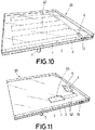
- Figure 10 shows another exemplary embodiment of a mirror 20 on a supporting structure 7 constituting a single faceted heliostat type reflector.
- the mirror 20 comprises a first transparent protective layer 1, a reflecting layer 2 and a second protective layer 3. Both the first layer 1 and the second protective layer 3 could act as a supporting layer.
- a breakage sensor 4 has been included, connected to a power supply and breakage detection cable 42, both the sensor 4 and the cabling 42 being located, integrated in the second protective layer 3.
- the mirror 20 also comprises a connector 51 to which the components for power supply and data connection of the sensor 4 are connected.
- Figure 11 shows the last exemplary embodiment in which a mirror 20 is seen on a supporting structure 7, as in the case of Figures 9 and 10 , the mirror 20 having a first transparent protective layer 1, a reflecting layer 2 and a second protective layer 3. Both the first layer 1 and the second protective layer 3 could act as supporting layer of the mirror 20.
- the sensor 4 is located next to a battery 53 and next to a wireless antenna 6, all three integrated in the mirror, between the first layer 1 and the reflecting layer 2.
- the battery 53 is connected by means of power cabling 52 to the sensor 4, which is for example a tilt sensor, and the antenna 6 directly to the sensor 4.
- the wireless antenna 6 is used for wireless data transmission.
- a battery 53 that guarantees the life thereof during the lifespan of the mirror 20 will be used, since replacement thereof would be complicated, it being integrated in the mirror 20.
- a solution for replacing the battery and any other element integrated in the body of the mirror 20 that could be damaged or require replacement thereof, would consist of including accesses that are adequately watertight to the component, preferably through the second protective layer 3.
- sensors may be arranged facing towards the front of the mirror, towards the back or to one side depending on the type of sensor and the functions required thereof.
- Figure 12 shows two examples of multi-faceted solar reflectors, a parabolic trough on the left and a heliostat on the right, which include at least one mirror or facet according to the present invention.
- said reflectors comprise a single row of mirrors with at least one sensor integrated in each mirror, while the other mirrors of the other rows are mirrors that do not comprise a sensor integrated therein.
- the foregoing examples relate to sensors integrated in the body of a mirror, which, as mentioned previously, may or may not incorporate a processor. Furthermore, the description of the previous figures can be extended to those cases in which, in addition to a sensor and other described components, the mirror integrates a processor associated to the sensor but not incorporated in it, such that depending on whether or not there exists a processor in the mirror, a sensorized mirror or a smart mirror is made available.
- the senor, the means of connection and the power supply means can make up the same element or component integrated in the body of the mirror, regardless of whether or not said component incorporates a processor.
- the three mirrors are smart mirrors, i.e., those comprising a processor in addition to at least one sensor, transmission and power supply means.
- Figure13 shows a heliostat as a solar reflector with eight mirrors, three of which are mirrors according to the present invention and more specifically, smart mirrors. If each of said three smart mirrors has the capacity to measure its position thanks to, for example, a GPS (Global Positioning System) or differential GPS type sensor, they have the capacity to connect with each other and a processor in order to manage the information gathered by the sensor, the possibility of generating new additional information of interest for the control of the heliostat on which they are installed automatically appears.
- GPS Global Positioning System
- a possible method of implementation would include the following stages:
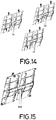
- Figure 14 shows three heliostats similar to those described previously in Figure 13 , i.e., three heliostats with eight mirrors each, which comprise three smart mirrors.
- the incorporation of said smart mirrors endows them with the capacity to connect with each other, thanks to the integrated processors and means of connection, as well as the capacity to analyze the information captured or gathered by the integrated sensors, such that they will be capable of analyzing the orientation of the neighboring heliostats, continuously analyzing the possibilities of collision, the shadows and blockages that can occur between them and making decisions that optimize production and safety of the plant in which said heliostats are installed.
- Figure 15 shows a heliostat with eight mirrors, four of which comprise a sensor, an active element, specifically a light device, for example a LED-type device, and one of said four mirrors comprises a second sensor, a vision device capable of capturing images of the surroundings of the heliostat and a processor, the latter therefore being a smart mirror according to the present invention.
- One objective of the sensors or light devices is that they can be seen by other elements or devices, external to the heliostat where they are installed, so that these other elements or devices can identify the positions thereof and consequently the overall position and orientation of the reflector on which they are installed. Additionally, these sensors or light devices can change color indicating an operational status or a failure of the mirror itself, of the reflector on which it is installed or of some other element of the field with which it establishes some kind of communication and exchanges information.
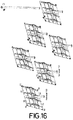
- Figure 16 shows a group of heliostats such as those of Figure 15 .
- smart mirrors with vision capacity will be able to identify the light devices of other smart mirrors and, thanks to the connection and processing capacity, will be able to calculate the position and orientation of neighboring heliostats and communicate it to said heliostats and/or a central control unit.
- another possible implementation is shown incorporating a vision system external to the heliostats placed in an elevated "O" position, such that it can observe and identify the light devices and consequently know the positions and orientations of the reflectors of a part of the solar field, thanks to the information captured by the vision system external to the heliostats as well as the information that the smart mirrors can provide to the processor or smart unit of said external vision system. Furthermore, thanks to the connection and processing capacities between the mirrors and/or an external control unit, it is possible to turn the light devices on or off in order to facilitate their identification.
- One possible method of actuating the four mirrors (21, 22, 23, 24) of a first heliostat (100) would include the following stages:
- a possible method of actuation of the smart mirror (25) including the sensor (45) located on a second heliostat (101) would include the following stages:
- FIG. 14 to 16 in spite of describing heliostats comprising mirrors according to the present invention, also describe associations or groups of heliostats that exchange information between each other thanks to the sensors integrated in the mirrors that make up said heliostats, as well as the processor that said sensors or mirrors incorporate.
- the group of heliostats with mirrors according to the present invention is referred to as an intelligent solar field or smart field. This concept refers to the connection capacity between different mirrors arranged in solar reflectors with the aim of exchanging or transmitting information captured by the sensors of the different mirrors.
- the central control is responsible for calculating, among others, the following specific parameters of the solar field: calculating the solar vector, calculating the reflected beam, refraction correction, calculating the required position of solar reflectors or heliostats, status thereof, offset adjustments, alarms, etc.
- the central control also carries out other functions not specific to the solar field, such as cloud detection, measuring meteorological parameters, calculating solar flux, calculating dirt levels, assessing the need for cleaning and repair operations, and which could be fully or partially assumed by a duly grouped assembly of mirrors according to the present invention.
- an intelligent solar field or smart field incorporates at least one mirror in a first reflector according to the present invention, i.e., integrating at least one sensor, means of connection and power supply means, and preferably a processor, giving rise in the latter case to a smart mirror, and it also incorporates an external processor, which can be located in another smart mirror of a second reflector or in a device with a processor in the solar field, such as, for example, the central control.
- the mirrors that are included in the intelligent solar field or smart field will be able to share with each other and/or with other elements of the solar field or plant, that are not mirrors, the information gathered and/or generated by the sensors and generate additional information based on the available information.
- the smart field can not only provide information of interest for managing the solar field but also incorporate self-diagnosis capacities being able to operate autonomously or semi-autonomously based on the information provided by the mirrors thereof, reducing communication needs with the central control and even assuming part of the features thereof.
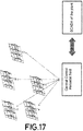
- Figure 17 shows a centralized management system or centralized operation of a central receiver plant with heliostats, wherein preferably at least one mirror of each heliostat has an integrated sensor, means of connection and power supply means, and preferably one processor, which may or may not be incorporated in the sensor, and if it is not incorporated therein, the processor should be integrated in the mirror (giving rise to a smart mirror), and a processor external to the mirrors, which in this case is a central control unit.
- mirrors preferably smart mirrors
- SCADA Supervisory Control and Data Acquisition
- other elements in the field such as solar receivers of parabolic trough reflectors or other monitoring systems such as solar flux measuring systems concentrated in tower plants, can take advantage of the information and/or signals that these mirrors provide in order to improve their operation.
- Figure 18 shows a decentralized management system wherein the mirrors of a central receiver plant with heliostats, also preferably smart mirrors, do not communicate the information they gather and/or generate to the central control, but based on the information and their capacities, they generate instructions for the operation of the solar field, assuming in part or totally the tasks of the central control unit, being able to execute said tasks themselves or share them with other external processors arranged in other elements or local devices in the solar field.
- SCADA Supervisory Control and Data Acquisition
Landscapes
- Engineering & Computer Science (AREA)
- Physics & Mathematics (AREA)
- Chemical & Material Sciences (AREA)
- Sustainable Development (AREA)
- Sustainable Energy (AREA)
- Thermal Sciences (AREA)
- Life Sciences & Earth Sciences (AREA)
- Combustion & Propulsion (AREA)
- Mechanical Engineering (AREA)
- General Engineering & Computer Science (AREA)
- General Physics & Mathematics (AREA)
- Optics & Photonics (AREA)
- Optical Elements Other Than Lenses (AREA)
Applications Claiming Priority (2)
| Application Number | Priority Date | Filing Date | Title |
|---|---|---|---|
| ES201631313A ES2663571B1 (es) | 2016-10-10 | 2016-10-10 | Espejo para reflector solar y procedimiento de ensamblaje |
| PCT/ES2017/070660 WO2018069558A1 (es) | 2016-10-10 | 2017-10-10 | Espejo para reflector solar, procedimiento de ensamblaje y sistema de gestión de espejos en un campo solar |
Publications (2)
| Publication Number | Publication Date |
|---|---|
| EP3524902A1 true EP3524902A1 (de) | 2019-08-14 |
| EP3524902B1 EP3524902B1 (de) | 2021-07-21 |
Family
ID=60421803
Family Applications (1)
| Application Number | Title | Priority Date | Filing Date |
|---|---|---|---|
| EP17801746.3A Active EP3524902B1 (de) | 2016-10-10 | 2017-10-10 | Spiegel für einen sonnenreflektor, verfahren für spiegelanordnung und verwaltungssystem in einem solarfeld |
Country Status (12)
| Country | Link |
|---|---|
| US (1) | US11079142B2 (de) |
| EP (1) | EP3524902B1 (de) |
| CN (1) | CN110770513B (de) |
| AU (1) | AU2017342097A1 (de) |
| CL (1) | CL2019000890A1 (de) |
| ES (2) | ES2663571B1 (de) |
| IL (1) | IL265924A (de) |
| MA (1) | MA46483B1 (de) |
| MX (1) | MX2019004138A (de) |
| PT (1) | PT3524902T (de) |
| WO (1) | WO2018069558A1 (de) |
| ZA (1) | ZA201902902B (de) |
Families Citing this family (4)
| Publication number | Priority date | Publication date | Assignee | Title |
|---|---|---|---|---|
| WO2020025107A1 (en) * | 2018-07-31 | 2020-02-06 | Carrascosa Perez Marco Antonio | Autonomous facet for solar concentrators and solar concentrator comprising said facet |
| DE102020125609A1 (de) * | 2020-09-30 | 2022-03-31 | Deutsches Zentrum für Luft- und Raumfahrt e.V. | Verfahren und system zur bestimmung eines zustands eines solarthermischen parabolrinnenkraftwerks |
| US20240167729A1 (en) * | 2022-11-18 | 2024-05-23 | Heliogen Holdings, Inc. | Heliostat optical panel assembly |
| CN120430199B (zh) * | 2025-07-04 | 2025-09-02 | 重庆长安汽车股份有限公司 | 一种体网格层推进方向的计算方法、装置、设备及介质 |
Family Cites Families (23)
| Publication number | Priority date | Publication date | Assignee | Title |
|---|---|---|---|---|
| NL54423C (de) * | 1937-06-30 | 1900-01-01 | ||
| US3278811A (en) * | 1960-10-04 | 1966-10-11 | Hayakawa Denki Kogyo Kabushiki | Radiation energy transducing device |
| JPH1079527A (ja) * | 1996-09-04 | 1998-03-24 | Toyota Motor Corp | 集光型太陽電池装置 |
| AUPR956801A0 (en) * | 2001-12-17 | 2002-01-24 | Kirk, Wayne Anthony | Solar energy conversion system |
| DE102006053758A1 (de) * | 2006-11-13 | 2008-05-15 | Deutsches Zentrum für Luft- und Raumfahrt e.V. | Verfahren zur Regelung der Ausrichtung eines Heliostaten auf einen Receiver, Heliostatenvorrichtung und Solarkraftwerk |
| CN101680685B (zh) * | 2007-03-30 | 2012-11-14 | 亿索乐公司 | 有集成的基于图像的追踪控制器的定日镜 |
| KR100913074B1 (ko) * | 2008-09-10 | 2009-08-21 | (주) 파루 | 고효율 집광용 태양광 추적 장치 및 그 방법 |
| WO2010078473A2 (en) * | 2009-01-05 | 2010-07-08 | Gustafson Vincent K | Solar energy utilization systems and methods |
| ES2346026B2 (es) * | 2009-01-12 | 2012-09-10 | Universidad Politécnica de Madrid | Sistema de paneles solares moviles para la edificacion |
| US20110000478A1 (en) * | 2009-07-02 | 2011-01-06 | Dan Reznik | Camera-based heliostat tracking controller |
| US8490619B2 (en) * | 2009-11-20 | 2013-07-23 | International Business Machines Corporation | Solar energy alignment and collection system |
| EP2534431A4 (de) * | 2010-02-10 | 2014-07-02 | Dipankar | Skalierbares und schnell einsetzbares master-slave-verfahren sowie vorrichtung zur verteilten verfolgung von sonnenkollektoren und anderen anwendungen |
| US9905709B2 (en) * | 2010-03-16 | 2018-02-27 | Philips Lighting Holdings B.V. | Photovoltaic cell device with switchable lighting/reflection |
| TWI384192B (zh) * | 2010-05-13 | 2013-02-01 | Univ Nat Central | 光感測系統及其控制方法 |
| FR2967242B1 (fr) * | 2010-11-04 | 2014-11-07 | Cray Valley Sa | Reflecteur solaire en materiau composite a base de resine renforcee par des fibres et utilisations dans des centrales solaires |
| EP2450644A1 (de) * | 2010-11-05 | 2012-05-09 | Daniele Tommei | Tragbarer Heliostat |
| WO2013083284A1 (en) * | 2011-12-08 | 2013-06-13 | Soitec Solar Gmbh | Apparatus for the industrial production of photovoltaic concentrator modules |
| CN104303031B (zh) * | 2012-01-24 | 2017-11-03 | 日光储备技术有限公司 | 用于光源感测以及指向的复合光学代理元件 |
| DE102012202370A1 (de) * | 2012-02-16 | 2013-08-22 | Webasto Ag | Verfahren zur Herstellung einer Fahrzeugheizung und Fahrzeugheizung |
| US9481017B2 (en) * | 2012-08-09 | 2016-11-01 | Jeffrey Scott Adler | Ramp cleaning device for solar energy technologies |
| JP6424737B2 (ja) * | 2015-05-25 | 2018-11-21 | 住友電気工業株式会社 | 集光型太陽光発電モジュール、集光型太陽光発電パネル、及び集光型太陽光発電装置 |
| JP6561661B2 (ja) * | 2015-08-03 | 2019-08-21 | 住友電気工業株式会社 | 集光型太陽光発電ユニット、集光型太陽光発電モジュール、集光型太陽光発電パネル及び集光型太陽光発電装置 |
| US20170063291A1 (en) * | 2015-09-02 | 2017-03-02 | Sung Chang Telecom Co., Ltd. | Fixed type solar generator equipped with reflector |
-
2016
- 2016-10-10 ES ES201631313A patent/ES2663571B1/es active Active
-
2017
- 2017-10-10 MX MX2019004138A patent/MX2019004138A/es unknown
- 2017-10-10 CN CN201780075919.9A patent/CN110770513B/zh not_active Expired - Fee Related
- 2017-10-10 US US16/340,882 patent/US11079142B2/en not_active Expired - Fee Related
- 2017-10-10 ES ES17801746T patent/ES2886461T3/es active Active
- 2017-10-10 EP EP17801746.3A patent/EP3524902B1/de active Active
- 2017-10-10 AU AU2017342097A patent/AU2017342097A1/en not_active Abandoned
- 2017-10-10 MA MA46483A patent/MA46483B1/fr unknown
- 2017-10-10 PT PT178017463T patent/PT3524902T/pt unknown
- 2017-10-10 WO PCT/ES2017/070660 patent/WO2018069558A1/es not_active Ceased
-
2019
- 2019-04-03 CL CL2019000890A patent/CL2019000890A1/es unknown
- 2019-04-08 IL IL265924A patent/IL265924A/en unknown
- 2019-05-09 ZA ZA2019/02902A patent/ZA201902902B/en unknown
Also Published As
| Publication number | Publication date |
|---|---|
| CN110770513A (zh) | 2020-02-07 |
| AU2017342097A1 (en) | 2019-05-02 |
| ZA201902902B (en) | 2020-10-28 |
| ES2886461T3 (es) | 2021-12-20 |
| IL265924A (en) | 2019-06-30 |
| US20190264952A1 (en) | 2019-08-29 |
| ES2663571A1 (es) | 2018-04-13 |
| US11079142B2 (en) | 2021-08-03 |
| PT3524902T (pt) | 2021-09-15 |
| CL2019000890A1 (es) | 2019-09-06 |
| ES2663571B1 (es) | 2019-01-15 |
| WO2018069558A1 (es) | 2018-04-19 |
| CN110770513B (zh) | 2021-10-12 |
| MA46483A (fr) | 2019-08-14 |
| EP3524902B1 (de) | 2021-07-21 |
| MA46483B1 (fr) | 2021-08-31 |
| MX2019004138A (es) | 2019-06-12 |
Similar Documents
| Publication | Publication Date | Title |
|---|---|---|
| EP3524902B1 (de) | Spiegel für einen sonnenreflektor, verfahren für spiegelanordnung und verwaltungssystem in einem solarfeld | |
| US11555481B2 (en) | Inspection device controller for an inspection device of a wind power plant | |
| US8104893B2 (en) | Calibration and tracking control of heliostats in a central tower receiver solar power plant | |
| EP2145137B1 (de) | Vorrichtung zum Leiten einfallender Strahlung | |
| CN103959035B (zh) | 用于定位在空中监测抛物面反射器的设备的方法和系统 | |
| US20110317876A1 (en) | Optical Control System for Heliostats | |
| AU2011279154A1 (en) | Robotic heliostat system and method of operation | |
| EP3798688A1 (de) | Optomechanisches system zur umwandlung von lichtenergie eines hochdirektional einfallenden lichtes oder zur übertragung von hochdirektional einfallendem licht sowie zur übertragung von diffusem einfallendem licht und zugehörige verfahren zur umwandlung und übertragung von lichtenergie | |
| CN111765926B (zh) | 一种智能物联网型塔用光纤接线盒 | |
| US10697669B2 (en) | CSP tracking | |
| CN212988440U (zh) | 一种智能物联网型塔用光纤接线盒 | |
| US8327838B1 (en) | Solar parabolic trough mirror/receiver alignment | |
| CN120908187A (zh) | 集成机器视觉的光伏电站无人机自动巡检系统 | |
| KR102010322B1 (ko) | 태양광 발전시스템의 관리방법 | |
| CN112930462A (zh) | 用于太阳能聚光器的自主刻面和包括所述刻面的太阳能聚光器 | |
| WO2022234315A1 (en) | Uav-based system and method for the characterization of the geometry of solar concentrating mirrors | |
| US20250002184A1 (en) | Unmanned aerial systems for use in solar energy installations | |
| EP4341619B1 (de) | Csp-system, sensoranordnung, verfahren und verwendung | |
| WO2024252419A1 (en) | A system and method for determining optimal tracking trajectory of bifacial photo voltaic panels | |
| CN116225078A (zh) | 一种定日镜的视觉跟踪装置及跟踪方法 | |
| TR2025014732A2 (tr) | Çok segmentli̇, gölgelemesi̇z ve güneş taki̇p kontrollü bi̇r yansitici si̇stem | |
| Liu et al. | Transformative Impacts of AI and Wireless Communication in CSP Heliostat Control Systems. Energies 2025, 18, 1069 | |
| Sharma et al. | Computer Vision and Automation | |
| ITRM20090129A1 (it) | Pannello riflettente in particolare per un impianto solare termico a concentrazione | |
| ITRM20130010U1 (it) | Impianto solare termico a concentrazione |
Legal Events
| Date | Code | Title | Description |
|---|---|---|---|
| STAA | Information on the status of an ep patent application or granted ep patent |
Free format text: STATUS: UNKNOWN |
|
| STAA | Information on the status of an ep patent application or granted ep patent |
Free format text: STATUS: THE INTERNATIONAL PUBLICATION HAS BEEN MADE |
|
| PUAI | Public reference made under article 153(3) epc to a published international application that has entered the european phase |
Free format text: ORIGINAL CODE: 0009012 |
|
| STAA | Information on the status of an ep patent application or granted ep patent |
Free format text: STATUS: REQUEST FOR EXAMINATION WAS MADE |
|
| 17P | Request for examination filed |
Effective date: 20190405 |
|
| AK | Designated contracting states |
Kind code of ref document: A1 Designated state(s): AL AT BE BG CH CY CZ DE DK EE ES FI FR GB GR HR HU IE IS IT LI LT LU LV MC MK MT NL NO PL PT RO RS SE SI SK SM TR |
|
| AX | Request for extension of the european patent |
Extension state: BA ME |
|
| DAX | Request for extension of the european patent (deleted) | ||
| RAV | Requested validation state of the european patent: fee paid |
Extension state: MA Effective date: 20190405 |
|
| STAA | Information on the status of an ep patent application or granted ep patent |
Free format text: STATUS: EXAMINATION IS IN PROGRESS |
|
| 17Q | First examination report despatched |
Effective date: 20200406 |
|
| GRAP | Despatch of communication of intention to grant a patent |
Free format text: ORIGINAL CODE: EPIDOSNIGR1 |
|
| STAA | Information on the status of an ep patent application or granted ep patent |
Free format text: STATUS: GRANT OF PATENT IS INTENDED |
|
| INTG | Intention to grant announced |
Effective date: 20210211 |
|
| GRAS | Grant fee paid |
Free format text: ORIGINAL CODE: EPIDOSNIGR3 |
|
| GRAA | (expected) grant |
Free format text: ORIGINAL CODE: 0009210 |
|
| STAA | Information on the status of an ep patent application or granted ep patent |
Free format text: STATUS: THE PATENT HAS BEEN GRANTED |
|
| AK | Designated contracting states |
Kind code of ref document: B1 Designated state(s): AL AT BE BG CH CY CZ DE DK EE ES FI FR GB GR HR HU IE IS IT LI LT LU LV MC MK MT NL NO PL PT RO RS SE SI SK SM TR |
|
| RAP3 | Party data changed (applicant data changed or rights of an application transferred) |
Owner name: FUNDACION CENER Owner name: FUNDACION TEKNIKER |
|
| REG | Reference to a national code |
Ref country code: GB Ref legal event code: FG4D |
|
| REG | Reference to a national code |
Ref country code: CH Ref legal event code: EP |
|
| REG | Reference to a national code |
Ref country code: DE Ref legal event code: R096 Ref document number: 602017042588 Country of ref document: DE |
|
| REG | Reference to a national code |
Ref country code: AT Ref legal event code: REF Ref document number: 1412941 Country of ref document: AT Kind code of ref document: T Effective date: 20210815 |
|
| REG | Reference to a national code |
Ref country code: IE Ref legal event code: FG4D |
|
| REG | Reference to a national code |
Ref country code: MA Ref legal event code: VAGR Ref document number: 46483 Country of ref document: MA Kind code of ref document: B1 |
|
| REG | Reference to a national code |
Ref country code: PT Ref legal event code: SC4A Ref document number: 3524902 Country of ref document: PT Date of ref document: 20210915 Kind code of ref document: T Free format text: AVAILABILITY OF NATIONAL TRANSLATION Effective date: 20210908 |
|
| PGFP | Annual fee paid to national office [announced via postgrant information from national office to epo] |
Ref country code: IT Payment date: 20210916 Year of fee payment: 5 |
|
| REG | Reference to a national code |
Ref country code: LT Ref legal event code: MG9D Ref country code: GR Ref legal event code: EP Ref document number: 20210402374 Country of ref document: GR Effective date: 20211013 |
|
| REG | Reference to a national code |
Ref country code: NL Ref legal event code: MP Effective date: 20210721 |
|
| PGFP | Annual fee paid to national office [announced via postgrant information from national office to epo] |
Ref country code: GR Payment date: 20210908 Year of fee payment: 5 |
|
| REG | Reference to a national code |
Ref country code: AT Ref legal event code: MK05 Ref document number: 1412941 Country of ref document: AT Kind code of ref document: T Effective date: 20210721 |
|
| REG | Reference to a national code |
Ref country code: ES Ref legal event code: FG2A Ref document number: 2886461 Country of ref document: ES Kind code of ref document: T3 Effective date: 20211220 |
|
| PGFP | Annual fee paid to national office [announced via postgrant information from national office to epo] |
Ref country code: PT Payment date: 20210908 Year of fee payment: 5 |
|
| PG25 | Lapsed in a contracting state [announced via postgrant information from national office to epo] |
Ref country code: NO Free format text: LAPSE BECAUSE OF FAILURE TO SUBMIT A TRANSLATION OF THE DESCRIPTION OR TO PAY THE FEE WITHIN THE PRESCRIBED TIME-LIMIT Effective date: 20211021 Ref country code: NL Free format text: LAPSE BECAUSE OF FAILURE TO SUBMIT A TRANSLATION OF THE DESCRIPTION OR TO PAY THE FEE WITHIN THE PRESCRIBED TIME-LIMIT Effective date: 20210721 Ref country code: AT Free format text: LAPSE BECAUSE OF FAILURE TO SUBMIT A TRANSLATION OF THE DESCRIPTION OR TO PAY THE FEE WITHIN THE PRESCRIBED TIME-LIMIT Effective date: 20210721 Ref country code: BG Free format text: LAPSE BECAUSE OF FAILURE TO SUBMIT A TRANSLATION OF THE DESCRIPTION OR TO PAY THE FEE WITHIN THE PRESCRIBED TIME-LIMIT Effective date: 20211021 Ref country code: LT Free format text: LAPSE BECAUSE OF FAILURE TO SUBMIT A TRANSLATION OF THE DESCRIPTION OR TO PAY THE FEE WITHIN THE PRESCRIBED TIME-LIMIT Effective date: 20210721 Ref country code: RS Free format text: LAPSE BECAUSE OF FAILURE TO SUBMIT A TRANSLATION OF THE DESCRIPTION OR TO PAY THE FEE WITHIN THE PRESCRIBED TIME-LIMIT Effective date: 20210721 Ref country code: SE Free format text: LAPSE BECAUSE OF FAILURE TO SUBMIT A TRANSLATION OF THE DESCRIPTION OR TO PAY THE FEE WITHIN THE PRESCRIBED TIME-LIMIT Effective date: 20210721 Ref country code: HR Free format text: LAPSE BECAUSE OF FAILURE TO SUBMIT A TRANSLATION OF THE DESCRIPTION OR TO PAY THE FEE WITHIN THE PRESCRIBED TIME-LIMIT Effective date: 20210721 Ref country code: FI Free format text: LAPSE BECAUSE OF FAILURE TO SUBMIT A TRANSLATION OF THE DESCRIPTION OR TO PAY THE FEE WITHIN THE PRESCRIBED TIME-LIMIT Effective date: 20210721 |
|
| PG25 | Lapsed in a contracting state [announced via postgrant information from national office to epo] |
Ref country code: PL Free format text: LAPSE BECAUSE OF FAILURE TO SUBMIT A TRANSLATION OF THE DESCRIPTION OR TO PAY THE FEE WITHIN THE PRESCRIBED TIME-LIMIT Effective date: 20210721 Ref country code: LV Free format text: LAPSE BECAUSE OF FAILURE TO SUBMIT A TRANSLATION OF THE DESCRIPTION OR TO PAY THE FEE WITHIN THE PRESCRIBED TIME-LIMIT Effective date: 20210721 |
|
| REG | Reference to a national code |
Ref country code: DE Ref legal event code: R097 Ref document number: 602017042588 Country of ref document: DE |
|
| PG25 | Lapsed in a contracting state [announced via postgrant information from national office to epo] |
Ref country code: DK Free format text: LAPSE BECAUSE OF FAILURE TO SUBMIT A TRANSLATION OF THE DESCRIPTION OR TO PAY THE FEE WITHIN THE PRESCRIBED TIME-LIMIT Effective date: 20210721 |
|
| REG | Reference to a national code |
Ref country code: DE Ref legal event code: R119 Ref document number: 602017042588 Country of ref document: DE |
|
| PLBE | No opposition filed within time limit |
Free format text: ORIGINAL CODE: 0009261 |
|
| STAA | Information on the status of an ep patent application or granted ep patent |
Free format text: STATUS: NO OPPOSITION FILED WITHIN TIME LIMIT |
|
| PG25 | Lapsed in a contracting state [announced via postgrant information from national office to epo] |
Ref country code: SM Free format text: LAPSE BECAUSE OF FAILURE TO SUBMIT A TRANSLATION OF THE DESCRIPTION OR TO PAY THE FEE WITHIN THE PRESCRIBED TIME-LIMIT Effective date: 20210721 Ref country code: SK Free format text: LAPSE BECAUSE OF FAILURE TO SUBMIT A TRANSLATION OF THE DESCRIPTION OR TO PAY THE FEE WITHIN THE PRESCRIBED TIME-LIMIT Effective date: 20210721 Ref country code: RO Free format text: LAPSE BECAUSE OF FAILURE TO SUBMIT A TRANSLATION OF THE DESCRIPTION OR TO PAY THE FEE WITHIN THE PRESCRIBED TIME-LIMIT Effective date: 20210721 Ref country code: EE Free format text: LAPSE BECAUSE OF FAILURE TO SUBMIT A TRANSLATION OF THE DESCRIPTION OR TO PAY THE FEE WITHIN THE PRESCRIBED TIME-LIMIT Effective date: 20210721 Ref country code: CZ Free format text: LAPSE BECAUSE OF FAILURE TO SUBMIT A TRANSLATION OF THE DESCRIPTION OR TO PAY THE FEE WITHIN THE PRESCRIBED TIME-LIMIT Effective date: 20210721 Ref country code: AL Free format text: LAPSE BECAUSE OF FAILURE TO SUBMIT A TRANSLATION OF THE DESCRIPTION OR TO PAY THE FEE WITHIN THE PRESCRIBED TIME-LIMIT Effective date: 20210721 |
|
| REG | Reference to a national code |
Ref country code: CH Ref legal event code: PL |
|
| REG | Reference to a national code |
Ref country code: BE Ref legal event code: MM Effective date: 20211031 |
|
| 26N | No opposition filed |
Effective date: 20220422 |
|
| GBPC | Gb: european patent ceased through non-payment of renewal fee |
Effective date: 20211021 |
|
| PG25 | Lapsed in a contracting state [announced via postgrant information from national office to epo] |
Ref country code: MC Free format text: LAPSE BECAUSE OF FAILURE TO SUBMIT A TRANSLATION OF THE DESCRIPTION OR TO PAY THE FEE WITHIN THE PRESCRIBED TIME-LIMIT Effective date: 20210721 |
|
| PG25 | Lapsed in a contracting state [announced via postgrant information from national office to epo] |
Ref country code: LU Free format text: LAPSE BECAUSE OF NON-PAYMENT OF DUE FEES Effective date: 20211010 Ref country code: GB Free format text: LAPSE BECAUSE OF NON-PAYMENT OF DUE FEES Effective date: 20211021 Ref country code: DE Free format text: LAPSE BECAUSE OF NON-PAYMENT OF DUE FEES Effective date: 20220503 Ref country code: BE Free format text: LAPSE BECAUSE OF NON-PAYMENT OF DUE FEES Effective date: 20211031 |
|
| PG25 | Lapsed in a contracting state [announced via postgrant information from national office to epo] |
Ref country code: LI Free format text: LAPSE BECAUSE OF NON-PAYMENT OF DUE FEES Effective date: 20211031 Ref country code: CH Free format text: LAPSE BECAUSE OF NON-PAYMENT OF DUE FEES Effective date: 20211031 |
|
| PG25 | Lapsed in a contracting state [announced via postgrant information from national office to epo] |
Ref country code: FR Free format text: LAPSE BECAUSE OF NON-PAYMENT OF DUE FEES Effective date: 20211031 |
|
| PG25 | Lapsed in a contracting state [announced via postgrant information from national office to epo] |
Ref country code: IE Free format text: LAPSE BECAUSE OF NON-PAYMENT OF DUE FEES Effective date: 20211010 |
|
| PG25 | Lapsed in a contracting state [announced via postgrant information from national office to epo] |
Ref country code: CY Free format text: LAPSE BECAUSE OF FAILURE TO SUBMIT A TRANSLATION OF THE DESCRIPTION OR TO PAY THE FEE WITHIN THE PRESCRIBED TIME-LIMIT Effective date: 20210721 |
|
| PG25 | Lapsed in a contracting state [announced via postgrant information from national office to epo] |
Ref country code: PT Free format text: LAPSE BECAUSE OF NON-PAYMENT OF DUE FEES Effective date: 20230410 Ref country code: HU Free format text: LAPSE BECAUSE OF FAILURE TO SUBMIT A TRANSLATION OF THE DESCRIPTION OR TO PAY THE FEE WITHIN THE PRESCRIBED TIME-LIMIT; INVALID AB INITIO Effective date: 20171010 |
|
| PG25 | Lapsed in a contracting state [announced via postgrant information from national office to epo] |
Ref country code: GR Free format text: LAPSE BECAUSE OF NON-PAYMENT OF DUE FEES Effective date: 20230508 |
|
| PG25 | Lapsed in a contracting state [announced via postgrant information from national office to epo] |
Ref country code: IT Free format text: LAPSE BECAUSE OF NON-PAYMENT OF DUE FEES Effective date: 20221010 |
|
| PG25 | Lapsed in a contracting state [announced via postgrant information from national office to epo] |
Ref country code: MK Free format text: LAPSE BECAUSE OF FAILURE TO SUBMIT A TRANSLATION OF THE DESCRIPTION OR TO PAY THE FEE WITHIN THE PRESCRIBED TIME-LIMIT Effective date: 20210721 |
|
| PG25 | Lapsed in a contracting state [announced via postgrant information from national office to epo] |
Ref country code: TR Free format text: LAPSE BECAUSE OF FAILURE TO SUBMIT A TRANSLATION OF THE DESCRIPTION OR TO PAY THE FEE WITHIN THE PRESCRIBED TIME-LIMIT Effective date: 20210721 |
|
| PG25 | Lapsed in a contracting state [announced via postgrant information from national office to epo] |
Ref country code: MT Free format text: LAPSE BECAUSE OF FAILURE TO SUBMIT A TRANSLATION OF THE DESCRIPTION OR TO PAY THE FEE WITHIN THE PRESCRIBED TIME-LIMIT Effective date: 20210721 |
|
| PGFP | Annual fee paid to national office [announced via postgrant information from national office to epo] |
Ref country code: ES Payment date: 20241104 Year of fee payment: 8 |
|
| VSFP | Annual fee paid to validation state [announced via postgrant information from national office to epo] |
Ref country code: MA Payment date: 20231031 Year of fee payment: 7 |
|
| VSFP | Annual fee paid to validation state [announced via postgrant information from national office to epo] |
Ref country code: MA Payment date: 20221004 Year of fee payment: 6 Ref country code: MA Payment date: 20210803 Year of fee payment: 5 |
|
| VSFP | Annual fee paid to validation state [announced via postgrant information from national office to epo] |
Ref country code: MA Payment date: 20241009 Year of fee payment: 8 |