EP3524940A2 - Détection distribuée de fibre optique - Google Patents
Détection distribuée de fibre optique Download PDFInfo
- Publication number
- EP3524940A2 EP3524940A2 EP18194951.2A EP18194951A EP3524940A2 EP 3524940 A2 EP3524940 A2 EP 3524940A2 EP 18194951 A EP18194951 A EP 18194951A EP 3524940 A2 EP3524940 A2 EP 3524940A2
- Authority
- EP
- European Patent Office
- Prior art keywords
- pulse
- samples
- phase
- channels
- pulses
- Prior art date
- Legal status (The legal status is an assumption and is not a legal conclusion. Google has not performed a legal analysis and makes no representation as to the accuracy of the status listed.)
- Withdrawn
Links
Images






Classifications
-
- G—PHYSICS
- G01—MEASURING; TESTING
- G01H—MEASUREMENT OF MECHANICAL VIBRATIONS OR ULTRASONIC, SONIC OR INFRASONIC WAVES
- G01H9/00—Measuring mechanical vibrations or ultrasonic, sonic or infrasonic waves by using radiation-sensitive means, e.g. optical means
- G01H9/004—Measuring mechanical vibrations or ultrasonic, sonic or infrasonic waves by using radiation-sensitive means, e.g. optical means using fibre optic sensors
-
- G—PHYSICS
- G01—MEASURING; TESTING
- G01D—MEASURING NOT SPECIALLY ADAPTED FOR A SPECIFIC VARIABLE; ARRANGEMENTS FOR MEASURING TWO OR MORE VARIABLES NOT COVERED IN A SINGLE OTHER SUBCLASS; TARIFF METERING APPARATUS; MEASURING OR TESTING NOT OTHERWISE PROVIDED FOR
- G01D5/00—Mechanical means for transferring the output of a sensing member; Means for converting the output of a sensing member to another variable where the form or nature of the sensing member does not constrain the means for converting; Transducers not specially adapted for a specific variable
- G01D5/26—Mechanical means for transferring the output of a sensing member; Means for converting the output of a sensing member to another variable where the form or nature of the sensing member does not constrain the means for converting; Transducers not specially adapted for a specific variable characterised by optical transfer means, i.e. using infrared, visible, or ultraviolet light
- G01D5/32—Mechanical means for transferring the output of a sensing member; Means for converting the output of a sensing member to another variable where the form or nature of the sensing member does not constrain the means for converting; Transducers not specially adapted for a specific variable characterised by optical transfer means, i.e. using infrared, visible, or ultraviolet light with attenuation or whole or partial obturation of beams of light
- G01D5/34—Mechanical means for transferring the output of a sensing member; Means for converting the output of a sensing member to another variable where the form or nature of the sensing member does not constrain the means for converting; Transducers not specially adapted for a specific variable characterised by optical transfer means, i.e. using infrared, visible, or ultraviolet light with attenuation or whole or partial obturation of beams of light the beams of light being detected by photocells
- G01D5/353—Mechanical means for transferring the output of a sensing member; Means for converting the output of a sensing member to another variable where the form or nature of the sensing member does not constrain the means for converting; Transducers not specially adapted for a specific variable characterised by optical transfer means, i.e. using infrared, visible, or ultraviolet light with attenuation or whole or partial obturation of beams of light the beams of light being detected by photocells influencing the transmission properties of an optical fibre
- G01D5/35306—Mechanical means for transferring the output of a sensing member; Means for converting the output of a sensing member to another variable where the form or nature of the sensing member does not constrain the means for converting; Transducers not specially adapted for a specific variable characterised by optical transfer means, i.e. using infrared, visible, or ultraviolet light with attenuation or whole or partial obturation of beams of light the beams of light being detected by photocells influencing the transmission properties of an optical fibre using an interferometer arrangement
- G01D5/35329—Mechanical means for transferring the output of a sensing member; Means for converting the output of a sensing member to another variable where the form or nature of the sensing member does not constrain the means for converting; Transducers not specially adapted for a specific variable characterised by optical transfer means, i.e. using infrared, visible, or ultraviolet light with attenuation or whole or partial obturation of beams of light the beams of light being detected by photocells influencing the transmission properties of an optical fibre using an interferometer arrangement using interferometer with two arms in transmission, e.g. Mach-Zender interferometer
-
- G—PHYSICS
- G01—MEASURING; TESTING
- G01D—MEASURING NOT SPECIALLY ADAPTED FOR A SPECIFIC VARIABLE; ARRANGEMENTS FOR MEASURING TWO OR MORE VARIABLES NOT COVERED IN A SINGLE OTHER SUBCLASS; TARIFF METERING APPARATUS; MEASURING OR TESTING NOT OTHERWISE PROVIDED FOR
- G01D1/00—Measuring arrangements giving results other than momentary value of variable, of general application
-
- G—PHYSICS
- G01—MEASURING; TESTING
- G01D—MEASURING NOT SPECIALLY ADAPTED FOR A SPECIFIC VARIABLE; ARRANGEMENTS FOR MEASURING TWO OR MORE VARIABLES NOT COVERED IN A SINGLE OTHER SUBCLASS; TARIFF METERING APPARATUS; MEASURING OR TESTING NOT OTHERWISE PROVIDED FOR
- G01D1/00—Measuring arrangements giving results other than momentary value of variable, of general application
- G01D1/02—Measuring arrangements giving results other than momentary value of variable, of general application giving mean values, e.g. root means square values
-
- G—PHYSICS
- G01—MEASURING; TESTING
- G01D—MEASURING NOT SPECIALLY ADAPTED FOR A SPECIFIC VARIABLE; ARRANGEMENTS FOR MEASURING TWO OR MORE VARIABLES NOT COVERED IN A SINGLE OTHER SUBCLASS; TARIFF METERING APPARATUS; MEASURING OR TESTING NOT OTHERWISE PROVIDED FOR
- G01D5/00—Mechanical means for transferring the output of a sensing member; Means for converting the output of a sensing member to another variable where the form or nature of the sensing member does not constrain the means for converting; Transducers not specially adapted for a specific variable
- G01D5/26—Mechanical means for transferring the output of a sensing member; Means for converting the output of a sensing member to another variable where the form or nature of the sensing member does not constrain the means for converting; Transducers not specially adapted for a specific variable characterised by optical transfer means, i.e. using infrared, visible, or ultraviolet light
- G01D5/32—Mechanical means for transferring the output of a sensing member; Means for converting the output of a sensing member to another variable where the form or nature of the sensing member does not constrain the means for converting; Transducers not specially adapted for a specific variable characterised by optical transfer means, i.e. using infrared, visible, or ultraviolet light with attenuation or whole or partial obturation of beams of light
- G01D5/34—Mechanical means for transferring the output of a sensing member; Means for converting the output of a sensing member to another variable where the form or nature of the sensing member does not constrain the means for converting; Transducers not specially adapted for a specific variable characterised by optical transfer means, i.e. using infrared, visible, or ultraviolet light with attenuation or whole or partial obturation of beams of light the beams of light being detected by photocells
- G01D5/353—Mechanical means for transferring the output of a sensing member; Means for converting the output of a sensing member to another variable where the form or nature of the sensing member does not constrain the means for converting; Transducers not specially adapted for a specific variable characterised by optical transfer means, i.e. using infrared, visible, or ultraviolet light with attenuation or whole or partial obturation of beams of light the beams of light being detected by photocells influencing the transmission properties of an optical fibre
- G01D5/35303—Mechanical means for transferring the output of a sensing member; Means for converting the output of a sensing member to another variable where the form or nature of the sensing member does not constrain the means for converting; Transducers not specially adapted for a specific variable characterised by optical transfer means, i.e. using infrared, visible, or ultraviolet light with attenuation or whole or partial obturation of beams of light the beams of light being detected by photocells influencing the transmission properties of an optical fibre using a reference fibre, e.g. interferometric devices
-
- G—PHYSICS
- G01—MEASURING; TESTING
- G01D—MEASURING NOT SPECIALLY ADAPTED FOR A SPECIFIC VARIABLE; ARRANGEMENTS FOR MEASURING TWO OR MORE VARIABLES NOT COVERED IN A SINGLE OTHER SUBCLASS; TARIFF METERING APPARATUS; MEASURING OR TESTING NOT OTHERWISE PROVIDED FOR
- G01D5/00—Mechanical means for transferring the output of a sensing member; Means for converting the output of a sensing member to another variable where the form or nature of the sensing member does not constrain the means for converting; Transducers not specially adapted for a specific variable
- G01D5/26—Mechanical means for transferring the output of a sensing member; Means for converting the output of a sensing member to another variable where the form or nature of the sensing member does not constrain the means for converting; Transducers not specially adapted for a specific variable characterised by optical transfer means, i.e. using infrared, visible, or ultraviolet light
- G01D5/32—Mechanical means for transferring the output of a sensing member; Means for converting the output of a sensing member to another variable where the form or nature of the sensing member does not constrain the means for converting; Transducers not specially adapted for a specific variable characterised by optical transfer means, i.e. using infrared, visible, or ultraviolet light with attenuation or whole or partial obturation of beams of light
- G01D5/34—Mechanical means for transferring the output of a sensing member; Means for converting the output of a sensing member to another variable where the form or nature of the sensing member does not constrain the means for converting; Transducers not specially adapted for a specific variable characterised by optical transfer means, i.e. using infrared, visible, or ultraviolet light with attenuation or whole or partial obturation of beams of light the beams of light being detected by photocells
- G01D5/353—Mechanical means for transferring the output of a sensing member; Means for converting the output of a sensing member to another variable where the form or nature of the sensing member does not constrain the means for converting; Transducers not specially adapted for a specific variable characterised by optical transfer means, i.e. using infrared, visible, or ultraviolet light with attenuation or whole or partial obturation of beams of light the beams of light being detected by photocells influencing the transmission properties of an optical fibre
- G01D5/35306—Mechanical means for transferring the output of a sensing member; Means for converting the output of a sensing member to another variable where the form or nature of the sensing member does not constrain the means for converting; Transducers not specially adapted for a specific variable characterised by optical transfer means, i.e. using infrared, visible, or ultraviolet light with attenuation or whole or partial obturation of beams of light the beams of light being detected by photocells influencing the transmission properties of an optical fibre using an interferometer arrangement
-
- G—PHYSICS
- G01—MEASURING; TESTING
- G01D—MEASURING NOT SPECIALLY ADAPTED FOR A SPECIFIC VARIABLE; ARRANGEMENTS FOR MEASURING TWO OR MORE VARIABLES NOT COVERED IN A SINGLE OTHER SUBCLASS; TARIFF METERING APPARATUS; MEASURING OR TESTING NOT OTHERWISE PROVIDED FOR
- G01D5/00—Mechanical means for transferring the output of a sensing member; Means for converting the output of a sensing member to another variable where the form or nature of the sensing member does not constrain the means for converting; Transducers not specially adapted for a specific variable
- G01D5/26—Mechanical means for transferring the output of a sensing member; Means for converting the output of a sensing member to another variable where the form or nature of the sensing member does not constrain the means for converting; Transducers not specially adapted for a specific variable characterised by optical transfer means, i.e. using infrared, visible, or ultraviolet light
- G01D5/32—Mechanical means for transferring the output of a sensing member; Means for converting the output of a sensing member to another variable where the form or nature of the sensing member does not constrain the means for converting; Transducers not specially adapted for a specific variable characterised by optical transfer means, i.e. using infrared, visible, or ultraviolet light with attenuation or whole or partial obturation of beams of light
- G01D5/34—Mechanical means for transferring the output of a sensing member; Means for converting the output of a sensing member to another variable where the form or nature of the sensing member does not constrain the means for converting; Transducers not specially adapted for a specific variable characterised by optical transfer means, i.e. using infrared, visible, or ultraviolet light with attenuation or whole or partial obturation of beams of light the beams of light being detected by photocells
- G01D5/353—Mechanical means for transferring the output of a sensing member; Means for converting the output of a sensing member to another variable where the form or nature of the sensing member does not constrain the means for converting; Transducers not specially adapted for a specific variable characterised by optical transfer means, i.e. using infrared, visible, or ultraviolet light with attenuation or whole or partial obturation of beams of light the beams of light being detected by photocells influencing the transmission properties of an optical fibre
- G01D5/35306—Mechanical means for transferring the output of a sensing member; Means for converting the output of a sensing member to another variable where the form or nature of the sensing member does not constrain the means for converting; Transducers not specially adapted for a specific variable characterised by optical transfer means, i.e. using infrared, visible, or ultraviolet light with attenuation or whole or partial obturation of beams of light the beams of light being detected by photocells influencing the transmission properties of an optical fibre using an interferometer arrangement
- G01D5/35309—Mechanical means for transferring the output of a sensing member; Means for converting the output of a sensing member to another variable where the form or nature of the sensing member does not constrain the means for converting; Transducers not specially adapted for a specific variable characterised by optical transfer means, i.e. using infrared, visible, or ultraviolet light with attenuation or whole or partial obturation of beams of light the beams of light being detected by photocells influencing the transmission properties of an optical fibre using an interferometer arrangement using multiple waves interferometer
- G01D5/35312—Mechanical means for transferring the output of a sensing member; Means for converting the output of a sensing member to another variable where the form or nature of the sensing member does not constrain the means for converting; Transducers not specially adapted for a specific variable characterised by optical transfer means, i.e. using infrared, visible, or ultraviolet light with attenuation or whole or partial obturation of beams of light the beams of light being detected by photocells influencing the transmission properties of an optical fibre using an interferometer arrangement using multiple waves interferometer using a Fabry Perot
-
- G—PHYSICS
- G01—MEASURING; TESTING
- G01D—MEASURING NOT SPECIALLY ADAPTED FOR A SPECIFIC VARIABLE; ARRANGEMENTS FOR MEASURING TWO OR MORE VARIABLES NOT COVERED IN A SINGLE OTHER SUBCLASS; TARIFF METERING APPARATUS; MEASURING OR TESTING NOT OTHERWISE PROVIDED FOR
- G01D5/00—Mechanical means for transferring the output of a sensing member; Means for converting the output of a sensing member to another variable where the form or nature of the sensing member does not constrain the means for converting; Transducers not specially adapted for a specific variable
- G01D5/26—Mechanical means for transferring the output of a sensing member; Means for converting the output of a sensing member to another variable where the form or nature of the sensing member does not constrain the means for converting; Transducers not specially adapted for a specific variable characterised by optical transfer means, i.e. using infrared, visible, or ultraviolet light
- G01D5/32—Mechanical means for transferring the output of a sensing member; Means for converting the output of a sensing member to another variable where the form or nature of the sensing member does not constrain the means for converting; Transducers not specially adapted for a specific variable characterised by optical transfer means, i.e. using infrared, visible, or ultraviolet light with attenuation or whole or partial obturation of beams of light
- G01D5/34—Mechanical means for transferring the output of a sensing member; Means for converting the output of a sensing member to another variable where the form or nature of the sensing member does not constrain the means for converting; Transducers not specially adapted for a specific variable characterised by optical transfer means, i.e. using infrared, visible, or ultraviolet light with attenuation or whole or partial obturation of beams of light the beams of light being detected by photocells
- G01D5/353—Mechanical means for transferring the output of a sensing member; Means for converting the output of a sensing member to another variable where the form or nature of the sensing member does not constrain the means for converting; Transducers not specially adapted for a specific variable characterised by optical transfer means, i.e. using infrared, visible, or ultraviolet light with attenuation or whole or partial obturation of beams of light the beams of light being detected by photocells influencing the transmission properties of an optical fibre
- G01D5/35338—Mechanical means for transferring the output of a sensing member; Means for converting the output of a sensing member to another variable where the form or nature of the sensing member does not constrain the means for converting; Transducers not specially adapted for a specific variable characterised by optical transfer means, i.e. using infrared, visible, or ultraviolet light with attenuation or whole or partial obturation of beams of light the beams of light being detected by photocells influencing the transmission properties of an optical fibre using other arrangements than interferometer arrangements
- G01D5/35341—Sensor working in transmission
- G01D5/35345—Sensor working in transmission using Amplitude variations to detect the measured quantity
-
- G—PHYSICS
- G01—MEASURING; TESTING
- G01D—MEASURING NOT SPECIALLY ADAPTED FOR A SPECIFIC VARIABLE; ARRANGEMENTS FOR MEASURING TWO OR MORE VARIABLES NOT COVERED IN A SINGLE OTHER SUBCLASS; TARIFF METERING APPARATUS; MEASURING OR TESTING NOT OTHERWISE PROVIDED FOR
- G01D5/00—Mechanical means for transferring the output of a sensing member; Means for converting the output of a sensing member to another variable where the form or nature of the sensing member does not constrain the means for converting; Transducers not specially adapted for a specific variable
- G01D5/26—Mechanical means for transferring the output of a sensing member; Means for converting the output of a sensing member to another variable where the form or nature of the sensing member does not constrain the means for converting; Transducers not specially adapted for a specific variable characterised by optical transfer means, i.e. using infrared, visible, or ultraviolet light
- G01D5/32—Mechanical means for transferring the output of a sensing member; Means for converting the output of a sensing member to another variable where the form or nature of the sensing member does not constrain the means for converting; Transducers not specially adapted for a specific variable characterised by optical transfer means, i.e. using infrared, visible, or ultraviolet light with attenuation or whole or partial obturation of beams of light
- G01D5/34—Mechanical means for transferring the output of a sensing member; Means for converting the output of a sensing member to another variable where the form or nature of the sensing member does not constrain the means for converting; Transducers not specially adapted for a specific variable characterised by optical transfer means, i.e. using infrared, visible, or ultraviolet light with attenuation or whole or partial obturation of beams of light the beams of light being detected by photocells
- G01D5/353—Mechanical means for transferring the output of a sensing member; Means for converting the output of a sensing member to another variable where the form or nature of the sensing member does not constrain the means for converting; Transducers not specially adapted for a specific variable characterised by optical transfer means, i.e. using infrared, visible, or ultraviolet light with attenuation or whole or partial obturation of beams of light the beams of light being detected by photocells influencing the transmission properties of an optical fibre
- G01D5/35338—Mechanical means for transferring the output of a sensing member; Means for converting the output of a sensing member to another variable where the form or nature of the sensing member does not constrain the means for converting; Transducers not specially adapted for a specific variable characterised by optical transfer means, i.e. using infrared, visible, or ultraviolet light with attenuation or whole or partial obturation of beams of light the beams of light being detected by photocells influencing the transmission properties of an optical fibre using other arrangements than interferometer arrangements
- G01D5/35354—Sensor working in reflection
- G01D5/35358—Sensor working in reflection using backscattering to detect the measured quantity
-
- G—PHYSICS
- G01—MEASURING; TESTING
- G01D—MEASURING NOT SPECIALLY ADAPTED FOR A SPECIFIC VARIABLE; ARRANGEMENTS FOR MEASURING TWO OR MORE VARIABLES NOT COVERED IN A SINGLE OTHER SUBCLASS; TARIFF METERING APPARATUS; MEASURING OR TESTING NOT OTHERWISE PROVIDED FOR
- G01D5/00—Mechanical means for transferring the output of a sensing member; Means for converting the output of a sensing member to another variable where the form or nature of the sensing member does not constrain the means for converting; Transducers not specially adapted for a specific variable
- G01D5/26—Mechanical means for transferring the output of a sensing member; Means for converting the output of a sensing member to another variable where the form or nature of the sensing member does not constrain the means for converting; Transducers not specially adapted for a specific variable characterised by optical transfer means, i.e. using infrared, visible, or ultraviolet light
- G01D5/32—Mechanical means for transferring the output of a sensing member; Means for converting the output of a sensing member to another variable where the form or nature of the sensing member does not constrain the means for converting; Transducers not specially adapted for a specific variable characterised by optical transfer means, i.e. using infrared, visible, or ultraviolet light with attenuation or whole or partial obturation of beams of light
- G01D5/34—Mechanical means for transferring the output of a sensing member; Means for converting the output of a sensing member to another variable where the form or nature of the sensing member does not constrain the means for converting; Transducers not specially adapted for a specific variable characterised by optical transfer means, i.e. using infrared, visible, or ultraviolet light with attenuation or whole or partial obturation of beams of light the beams of light being detected by photocells
- G01D5/353—Mechanical means for transferring the output of a sensing member; Means for converting the output of a sensing member to another variable where the form or nature of the sensing member does not constrain the means for converting; Transducers not specially adapted for a specific variable characterised by optical transfer means, i.e. using infrared, visible, or ultraviolet light with attenuation or whole or partial obturation of beams of light the beams of light being detected by photocells influencing the transmission properties of an optical fibre
- G01D5/35338—Mechanical means for transferring the output of a sensing member; Means for converting the output of a sensing member to another variable where the form or nature of the sensing member does not constrain the means for converting; Transducers not specially adapted for a specific variable characterised by optical transfer means, i.e. using infrared, visible, or ultraviolet light with attenuation or whole or partial obturation of beams of light the beams of light being detected by photocells influencing the transmission properties of an optical fibre using other arrangements than interferometer arrangements
- G01D5/35354—Sensor working in reflection
- G01D5/35358—Sensor working in reflection using backscattering to detect the measured quantity
- G01D5/35361—Sensor working in reflection using backscattering to detect the measured quantity using elastic backscattering to detect the measured quantity, e.g. using Rayleigh backscattering
-
- G—PHYSICS
- G01—MEASURING; TESTING
- G01D—MEASURING NOT SPECIALLY ADAPTED FOR A SPECIFIC VARIABLE; ARRANGEMENTS FOR MEASURING TWO OR MORE VARIABLES NOT COVERED IN A SINGLE OTHER SUBCLASS; TARIFF METERING APPARATUS; MEASURING OR TESTING NOT OTHERWISE PROVIDED FOR
- G01D5/00—Mechanical means for transferring the output of a sensing member; Means for converting the output of a sensing member to another variable where the form or nature of the sensing member does not constrain the means for converting; Transducers not specially adapted for a specific variable
- G01D5/26—Mechanical means for transferring the output of a sensing member; Means for converting the output of a sensing member to another variable where the form or nature of the sensing member does not constrain the means for converting; Transducers not specially adapted for a specific variable characterised by optical transfer means, i.e. using infrared, visible, or ultraviolet light
- G01D5/32—Mechanical means for transferring the output of a sensing member; Means for converting the output of a sensing member to another variable where the form or nature of the sensing member does not constrain the means for converting; Transducers not specially adapted for a specific variable characterised by optical transfer means, i.e. using infrared, visible, or ultraviolet light with attenuation or whole or partial obturation of beams of light
- G01D5/34—Mechanical means for transferring the output of a sensing member; Means for converting the output of a sensing member to another variable where the form or nature of the sensing member does not constrain the means for converting; Transducers not specially adapted for a specific variable characterised by optical transfer means, i.e. using infrared, visible, or ultraviolet light with attenuation or whole or partial obturation of beams of light the beams of light being detected by photocells
- G01D5/353—Mechanical means for transferring the output of a sensing member; Means for converting the output of a sensing member to another variable where the form or nature of the sensing member does not constrain the means for converting; Transducers not specially adapted for a specific variable characterised by optical transfer means, i.e. using infrared, visible, or ultraviolet light with attenuation or whole or partial obturation of beams of light the beams of light being detected by photocells influencing the transmission properties of an optical fibre
- G01D5/35338—Mechanical means for transferring the output of a sensing member; Means for converting the output of a sensing member to another variable where the form or nature of the sensing member does not constrain the means for converting; Transducers not specially adapted for a specific variable characterised by optical transfer means, i.e. using infrared, visible, or ultraviolet light with attenuation or whole or partial obturation of beams of light the beams of light being detected by photocells influencing the transmission properties of an optical fibre using other arrangements than interferometer arrangements
- G01D5/35354—Sensor working in reflection
- G01D5/35367—Sensor working in reflection using reflected light other than backscattered to detect the measured quantity
-
- G—PHYSICS
- G01—MEASURING; TESTING
- G01D—MEASURING NOT SPECIALLY ADAPTED FOR A SPECIFIC VARIABLE; ARRANGEMENTS FOR MEASURING TWO OR MORE VARIABLES NOT COVERED IN A SINGLE OTHER SUBCLASS; TARIFF METERING APPARATUS; MEASURING OR TESTING NOT OTHERWISE PROVIDED FOR
- G01D5/00—Mechanical means for transferring the output of a sensing member; Means for converting the output of a sensing member to another variable where the form or nature of the sensing member does not constrain the means for converting; Transducers not specially adapted for a specific variable
- G01D5/26—Mechanical means for transferring the output of a sensing member; Means for converting the output of a sensing member to another variable where the form or nature of the sensing member does not constrain the means for converting; Transducers not specially adapted for a specific variable characterised by optical transfer means, i.e. using infrared, visible, or ultraviolet light
- G01D5/32—Mechanical means for transferring the output of a sensing member; Means for converting the output of a sensing member to another variable where the form or nature of the sensing member does not constrain the means for converting; Transducers not specially adapted for a specific variable characterised by optical transfer means, i.e. using infrared, visible, or ultraviolet light with attenuation or whole or partial obturation of beams of light
- G01D5/34—Mechanical means for transferring the output of a sensing member; Means for converting the output of a sensing member to another variable where the form or nature of the sensing member does not constrain the means for converting; Transducers not specially adapted for a specific variable characterised by optical transfer means, i.e. using infrared, visible, or ultraviolet light with attenuation or whole or partial obturation of beams of light the beams of light being detected by photocells
- G01D5/353—Mechanical means for transferring the output of a sensing member; Means for converting the output of a sensing member to another variable where the form or nature of the sensing member does not constrain the means for converting; Transducers not specially adapted for a specific variable characterised by optical transfer means, i.e. using infrared, visible, or ultraviolet light with attenuation or whole or partial obturation of beams of light the beams of light being detected by photocells influencing the transmission properties of an optical fibre
- G01D5/35383—Mechanical means for transferring the output of a sensing member; Means for converting the output of a sensing member to another variable where the form or nature of the sensing member does not constrain the means for converting; Transducers not specially adapted for a specific variable characterised by optical transfer means, i.e. using infrared, visible, or ultraviolet light with attenuation or whole or partial obturation of beams of light the beams of light being detected by photocells influencing the transmission properties of an optical fibre using multiple sensor devices using multiplexing techniques
-
- G—PHYSICS
- G01—MEASURING; TESTING
- G01D—MEASURING NOT SPECIALLY ADAPTED FOR A SPECIFIC VARIABLE; ARRANGEMENTS FOR MEASURING TWO OR MORE VARIABLES NOT COVERED IN A SINGLE OTHER SUBCLASS; TARIFF METERING APPARATUS; MEASURING OR TESTING NOT OTHERWISE PROVIDED FOR
- G01D5/00—Mechanical means for transferring the output of a sensing member; Means for converting the output of a sensing member to another variable where the form or nature of the sensing member does not constrain the means for converting; Transducers not specially adapted for a specific variable
- G01D5/26—Mechanical means for transferring the output of a sensing member; Means for converting the output of a sensing member to another variable where the form or nature of the sensing member does not constrain the means for converting; Transducers not specially adapted for a specific variable characterised by optical transfer means, i.e. using infrared, visible, or ultraviolet light
- G01D5/32—Mechanical means for transferring the output of a sensing member; Means for converting the output of a sensing member to another variable where the form or nature of the sensing member does not constrain the means for converting; Transducers not specially adapted for a specific variable characterised by optical transfer means, i.e. using infrared, visible, or ultraviolet light with attenuation or whole or partial obturation of beams of light
- G01D5/34—Mechanical means for transferring the output of a sensing member; Means for converting the output of a sensing member to another variable where the form or nature of the sensing member does not constrain the means for converting; Transducers not specially adapted for a specific variable characterised by optical transfer means, i.e. using infrared, visible, or ultraviolet light with attenuation or whole or partial obturation of beams of light the beams of light being detected by photocells
- G01D5/353—Mechanical means for transferring the output of a sensing member; Means for converting the output of a sensing member to another variable where the form or nature of the sensing member does not constrain the means for converting; Transducers not specially adapted for a specific variable characterised by optical transfer means, i.e. using infrared, visible, or ultraviolet light with attenuation or whole or partial obturation of beams of light the beams of light being detected by photocells influencing the transmission properties of an optical fibre
- G01D5/35383—Mechanical means for transferring the output of a sensing member; Means for converting the output of a sensing member to another variable where the form or nature of the sensing member does not constrain the means for converting; Transducers not specially adapted for a specific variable characterised by optical transfer means, i.e. using infrared, visible, or ultraviolet light with attenuation or whole or partial obturation of beams of light the beams of light being detected by photocells influencing the transmission properties of an optical fibre using multiple sensor devices using multiplexing techniques
- G01D5/35387—Mechanical means for transferring the output of a sensing member; Means for converting the output of a sensing member to another variable where the form or nature of the sensing member does not constrain the means for converting; Transducers not specially adapted for a specific variable characterised by optical transfer means, i.e. using infrared, visible, or ultraviolet light with attenuation or whole or partial obturation of beams of light the beams of light being detected by photocells influencing the transmission properties of an optical fibre using multiple sensor devices using multiplexing techniques using wavelength division multiplexing
-
- G—PHYSICS
- G01—MEASURING; TESTING
- G01D—MEASURING NOT SPECIALLY ADAPTED FOR A SPECIFIC VARIABLE; ARRANGEMENTS FOR MEASURING TWO OR MORE VARIABLES NOT COVERED IN A SINGLE OTHER SUBCLASS; TARIFF METERING APPARATUS; MEASURING OR TESTING NOT OTHERWISE PROVIDED FOR
- G01D5/00—Mechanical means for transferring the output of a sensing member; Means for converting the output of a sensing member to another variable where the form or nature of the sensing member does not constrain the means for converting; Transducers not specially adapted for a specific variable
- G01D5/26—Mechanical means for transferring the output of a sensing member; Means for converting the output of a sensing member to another variable where the form or nature of the sensing member does not constrain the means for converting; Transducers not specially adapted for a specific variable characterised by optical transfer means, i.e. using infrared, visible, or ultraviolet light
- G01D5/32—Mechanical means for transferring the output of a sensing member; Means for converting the output of a sensing member to another variable where the form or nature of the sensing member does not constrain the means for converting; Transducers not specially adapted for a specific variable characterised by optical transfer means, i.e. using infrared, visible, or ultraviolet light with attenuation or whole or partial obturation of beams of light
- G01D5/34—Mechanical means for transferring the output of a sensing member; Means for converting the output of a sensing member to another variable where the form or nature of the sensing member does not constrain the means for converting; Transducers not specially adapted for a specific variable characterised by optical transfer means, i.e. using infrared, visible, or ultraviolet light with attenuation or whole or partial obturation of beams of light the beams of light being detected by photocells
- G01D5/353—Mechanical means for transferring the output of a sensing member; Means for converting the output of a sensing member to another variable where the form or nature of the sensing member does not constrain the means for converting; Transducers not specially adapted for a specific variable characterised by optical transfer means, i.e. using infrared, visible, or ultraviolet light with attenuation or whole or partial obturation of beams of light the beams of light being detected by photocells influencing the transmission properties of an optical fibre
- G01D5/35383—Mechanical means for transferring the output of a sensing member; Means for converting the output of a sensing member to another variable where the form or nature of the sensing member does not constrain the means for converting; Transducers not specially adapted for a specific variable characterised by optical transfer means, i.e. using infrared, visible, or ultraviolet light with attenuation or whole or partial obturation of beams of light the beams of light being detected by photocells influencing the transmission properties of an optical fibre using multiple sensor devices using multiplexing techniques
- G01D5/3539—Mechanical means for transferring the output of a sensing member; Means for converting the output of a sensing member to another variable where the form or nature of the sensing member does not constrain the means for converting; Transducers not specially adapted for a specific variable characterised by optical transfer means, i.e. using infrared, visible, or ultraviolet light with attenuation or whole or partial obturation of beams of light the beams of light being detected by photocells influencing the transmission properties of an optical fibre using multiple sensor devices using multiplexing techniques using time division multiplexing
-
- G—PHYSICS
- G01—MEASURING; TESTING
- G01D—MEASURING NOT SPECIALLY ADAPTED FOR A SPECIFIC VARIABLE; ARRANGEMENTS FOR MEASURING TWO OR MORE VARIABLES NOT COVERED IN A SINGLE OTHER SUBCLASS; TARIFF METERING APPARATUS; MEASURING OR TESTING NOT OTHERWISE PROVIDED FOR
- G01D5/00—Mechanical means for transferring the output of a sensing member; Means for converting the output of a sensing member to another variable where the form or nature of the sensing member does not constrain the means for converting; Transducers not specially adapted for a specific variable
- G01D5/26—Mechanical means for transferring the output of a sensing member; Means for converting the output of a sensing member to another variable where the form or nature of the sensing member does not constrain the means for converting; Transducers not specially adapted for a specific variable characterised by optical transfer means, i.e. using infrared, visible, or ultraviolet light
- G01D5/32—Mechanical means for transferring the output of a sensing member; Means for converting the output of a sensing member to another variable where the form or nature of the sensing member does not constrain the means for converting; Transducers not specially adapted for a specific variable characterised by optical transfer means, i.e. using infrared, visible, or ultraviolet light with attenuation or whole or partial obturation of beams of light
- G01D5/34—Mechanical means for transferring the output of a sensing member; Means for converting the output of a sensing member to another variable where the form or nature of the sensing member does not constrain the means for converting; Transducers not specially adapted for a specific variable characterised by optical transfer means, i.e. using infrared, visible, or ultraviolet light with attenuation or whole or partial obturation of beams of light the beams of light being detected by photocells
- G01D5/353—Mechanical means for transferring the output of a sensing member; Means for converting the output of a sensing member to another variable where the form or nature of the sensing member does not constrain the means for converting; Transducers not specially adapted for a specific variable characterised by optical transfer means, i.e. using infrared, visible, or ultraviolet light with attenuation or whole or partial obturation of beams of light the beams of light being detected by photocells influencing the transmission properties of an optical fibre
- G01D5/35383—Mechanical means for transferring the output of a sensing member; Means for converting the output of a sensing member to another variable where the form or nature of the sensing member does not constrain the means for converting; Transducers not specially adapted for a specific variable characterised by optical transfer means, i.e. using infrared, visible, or ultraviolet light with attenuation or whole or partial obturation of beams of light the beams of light being detected by photocells influencing the transmission properties of an optical fibre using multiple sensor devices using multiplexing techniques
- G01D5/35393—Mechanical means for transferring the output of a sensing member; Means for converting the output of a sensing member to another variable where the form or nature of the sensing member does not constrain the means for converting; Transducers not specially adapted for a specific variable characterised by optical transfer means, i.e. using infrared, visible, or ultraviolet light with attenuation or whole or partial obturation of beams of light the beams of light being detected by photocells influencing the transmission properties of an optical fibre using multiple sensor devices using multiplexing techniques using frequency division multiplexing
-
- G—PHYSICS
- G01—MEASURING; TESTING
- G01D—MEASURING NOT SPECIALLY ADAPTED FOR A SPECIFIC VARIABLE; ARRANGEMENTS FOR MEASURING TWO OR MORE VARIABLES NOT COVERED IN A SINGLE OTHER SUBCLASS; TARIFF METERING APPARATUS; MEASURING OR TESTING NOT OTHERWISE PROVIDED FOR
- G01D5/00—Mechanical means for transferring the output of a sensing member; Means for converting the output of a sensing member to another variable where the form or nature of the sensing member does not constrain the means for converting; Transducers not specially adapted for a specific variable
- G01D5/26—Mechanical means for transferring the output of a sensing member; Means for converting the output of a sensing member to another variable where the form or nature of the sensing member does not constrain the means for converting; Transducers not specially adapted for a specific variable characterised by optical transfer means, i.e. using infrared, visible, or ultraviolet light
- G01D5/32—Mechanical means for transferring the output of a sensing member; Means for converting the output of a sensing member to another variable where the form or nature of the sensing member does not constrain the means for converting; Transducers not specially adapted for a specific variable characterised by optical transfer means, i.e. using infrared, visible, or ultraviolet light with attenuation or whole or partial obturation of beams of light
- G01D5/34—Mechanical means for transferring the output of a sensing member; Means for converting the output of a sensing member to another variable where the form or nature of the sensing member does not constrain the means for converting; Transducers not specially adapted for a specific variable characterised by optical transfer means, i.e. using infrared, visible, or ultraviolet light with attenuation or whole or partial obturation of beams of light the beams of light being detected by photocells
- G01D5/353—Mechanical means for transferring the output of a sensing member; Means for converting the output of a sensing member to another variable where the form or nature of the sensing member does not constrain the means for converting; Transducers not specially adapted for a specific variable characterised by optical transfer means, i.e. using infrared, visible, or ultraviolet light with attenuation or whole or partial obturation of beams of light the beams of light being detected by photocells influencing the transmission properties of an optical fibre
- G01D5/35383—Mechanical means for transferring the output of a sensing member; Means for converting the output of a sensing member to another variable where the form or nature of the sensing member does not constrain the means for converting; Transducers not specially adapted for a specific variable characterised by optical transfer means, i.e. using infrared, visible, or ultraviolet light with attenuation or whole or partial obturation of beams of light the beams of light being detected by photocells influencing the transmission properties of an optical fibre using multiple sensor devices using multiplexing techniques
- G01D5/35396—Mechanical means for transferring the output of a sensing member; Means for converting the output of a sensing member to another variable where the form or nature of the sensing member does not constrain the means for converting; Transducers not specially adapted for a specific variable characterised by optical transfer means, i.e. using infrared, visible, or ultraviolet light with attenuation or whole or partial obturation of beams of light the beams of light being detected by photocells influencing the transmission properties of an optical fibre using multiple sensor devices using multiplexing techniques using other forms of multiplexing
Definitions
- the backscattered radiation reaching the detector will be scattered from intrinsic scattering sites within the optical fibre.
- the radiation reaching the detector at any instant will correspond to radiation backscattered from scattering sites which are distributed throughout one or more sections of the optical fibre (depending on the form of the interrogating radiation).
- the various backscattered signals will interfere at the detector and the resultant interference signal will have a phase characteristic which depends on the characteristics of the interrogating radiation, the optical path length to the scattering sites and also on the distribution of the scattering sites within the optical fibre. As the distribution of the scattering sites is effectively random the resulting interference signal has a random element.
- Any stimulus on the optical fibre which leads to an optical path length change within the optical fibre may result in a phase modulation in the backscatter signal for the relevant portion of the optical fibre, i.e. a change in the phase characteristic of the backscatter signal from a given portion of optical fibre over time.
- any stimulus such as an acoustic stimulus, affecting the optical fibre within that sensing portion may be detected.
- This embodiment of the invention therefore operates on the assumption that, after processing, the data from each channel should, under ideal non-faded conditions, reveal the same phase modulation.
- channels where the processed phase data is similar to the data from other channels may indicate that the relevant channels are all measuring the same stimulus correctly, whereas any channels where the processed data does not match that of the other channels may indicated a faded or noise dominated sample.
- only a subset of the processed values from the channels may be used to form the combined phase value.
- a quality metric based on the self-similarity of the demodulated phase values of the channels corresponding to the sensing portion of interest relies on the assumption that each of the various channels is experiencing the same general stimulus. This is a reasonable assumption in most instances but it may not be sufficient for some precision applications or where incident waves with high wavenumber may be expected. In such cases it may be desirable to apply some time adjustment to the phase values of each channel prior to assessment to take into account a direction of arrival of the acoustic stimulus, i.e. to apply some beamforming type techniques.
- the backscatter signal received at the detector may comprise radiation which is backscattered from one or more sections of the optical fibre, depending on the form of the interrogating radiation.
- the interrogating radiation will comprise one or more pulses of optical radiation (note, as used herein the term optical radiation will include infrared or ultraviolet radiation as well as radiation at visible wavelengths).
- the interrogating radiation to comprise two pulses separated by a gap then the backscatter radiation reaching the detector at any instant would arise from two separate sections of fibre, the two contributing sections being separated by a gap.
- the degree of overlap between contributing sections of optical fibre that contribute to different samples is determined by the time between the relevant samples and the form of the interrogating radiation. For instance, consider an individual pulse of interrogating radiation travelling in the optical fibre so as to define a contributing section of fibre at a first position for a first sample and at a second position for a second sample.
- the degree of overlap between the corresponding contribution sections depends on the duration of the pulse, which defines the spatial width of the pulse in the optical fibre, and also the time between the first and second samples. If the pulse has a duration T p and the time between the first and second samples is equal to a quarter of T P then three quarters (3/4) of the contributing section for the first sample will overlap with the contributing section for the second sample, i.e. there will be a 75% degree of overlap.
- the sampling rate of the detector may therefore be arranged with regard to the form of the interrogating radiation to acquire the diversity samples as described above.
- the interrogating radiation may comprise at least a first pulse having a first pulse duration and the plurality of samples are acquired such that the time difference between samples is greater than the first pulse duration for the majority of the plurality of samples.
- a first sample is acquired at a first sampling time then most of the rest of the plurality of samples are acquired at a sampling time which differs from the first sampling time by more than the pulse duration.
- the samples may be acquired such that the time difference between any two samples in the plurality of samples corresponding to the sensing portion of interest is at least 50% of the pulse duration.
- the time difference between any two samples may be 75% or more of the pulse duration and in some embodiments the time difference may be at least equal to the pulse duration.
- the optical source may be configured such that the interrogating radiation comprises a first pulse and a second pulse with a gap or delay between them, i.e. the interrogating radiation may comprise a pulse pair with a temporal (and hence, within the optical fibre, spatial) separation between the pulses of the pair.
- the duration (and hence spatial width) of the first pulse may be the same as the duration of the second pulse, although they need not be the same.
- the duration between the first and second pulses i.e. the time between end of the first pulse and beginning of the second pulse, may be equal to or greater than the pulse duration of the first and/or second pulse.
- the spatial width of one (and advantageously both) pulses may be shorter than the spatial separation between pulses.
- the gap between the first and second pulses may be at least twice the pulse width.
- a pulse structure that has relatively narrow pulse widths compared to the gap between pulses can be advantageous in terms of allowing diversity samples to be acquired within the maximum achievable spatial resolution of the sensor.
- the optical source may be configured such that the pulses of the pulse pair have a frequency difference between them, i.e. the first pulse has a different frequency to the second pulse.
- the frequency difference may define a carrier frequency such as described in GB2,442,745 .
- the pulse pairs have the same frequency configuration as one another.
- frequency configuration will be taken to mean the absolute frequencies of the pulses in the pulse pair. So if the pulses of a first pulse pair are at frequencies F1 and F2 respectively (which may or may not be the same frequency) then the frequencies of a second pulse pair are also F1 and F2 respectively.
- each pulse pair comprises pulses having a frequency difference between the pulses in the pair. As described above this will lead to a backscatter interference signal at a carrier frequency equal to the frequency difference between the pulses.
- the carrier frequency is related to the launch rate of the pulse pairs.
- this embodiment of the invention allows a carrier signal to be determined from launch-to-launch.
- a signal from each portion of fibre i.e. comprising samples of the backscatter radiation acquired at substantially the same time after launch of each pulse pair, can be demodulated at the relevant carrier frequency and used to derive a phase value for the appropriate section of fibre.
- the carrier frequency should be less than half the launch rate.
- the time between launch of pulse pairs may allow for a predetermined relative phase change of 90° in the interference signal at the carrier frequency.
- a 90° phase change allows an accurate carrier signal to be reproduced from launch-to-launch and reduces any unnecessary oversampling.
- the time period between launch of the first pulse pair and the second pulse pair may be equal to a quarter of the wave period at the carrier frequency. In other words the carrier frequency may be a quarter of the launch rate of the pulse pairs.
- This embodiment therefore uses the fact that the phase relationship of signals at two different frequencies, say F1 and F2, will change over time. In the time between launch of the successive pulse pairs there will be time for n cycles of a signal at a frequency F1 and for m cycles of a signal at a frequency of F2.
- This embodiment controls the frequencies, F1 and F2 of the pulses in a pair and the launch rate of the pulse pairs such that in the time between launches n - m has a desired value, for instance 0.25 when a 90° phase difference is desired.
- This embodiment therefore provides a backscatter interference signal wherein there is a variation in the relative phase difference between the pulses in successive pulse pairs.
- the returns from the successive pulse pairs can therefore be used to determine a phase value for the relevant channel which can then be subject to the quality metric as described above.
- the optical source may therefore comprise at least one laser and at least one phase shifter, such as an electro-optic modulator, arranged to modulate the laser output so as to produce the first and second pulse pairs.
- phase shifter such as an electro-optic modulator
- the method of the present invention can also be applied to the processing of data which has been previously acquired using a distributed fibre optic sensor, provided that a plurality of samples, advantageously substantially independent samples, are acquired for each sensing portion of interest.
- a method of processing data acquired from a distributed fibre optic sensor to determine any phase modulation comprising the steps of: taking a plurality of samples corresponding to radiation backscattered from at least part of a spatial sensing portion of interest of an optical fibre following launch of interrogating radiation into said optical fibre; dividing said plurality of samples into a plurality of processing channels; processing at least some of said plurality of processing channels to determine phase data for said channel; applying a quality metric to said processed channels; and combining the determined phase data for said channels into a phase value for said spatial sensing portion of interest based on the results of applying said quality metric.
- an aspect of the invention provides a distributed fibre optic sensor, especially a distributed acoustic sensor, that comprises a sampling detector configured to temporally oversample to acquire, in use, a plurality of samples for a sensing portion of interest and a processor configured to process said samples in separate diversity channels and to combine the result from said channels based on the similarity the resulting data from the processed channels.
- an interrogator unit of a distributed acoustic sensor is illustrated with respect to Figure 1 .
- the interrogator unit 100 is connected to an optical fibre 101 which acts as the sensing fibre.
- the sensing fibre is coupled to an output/input of the interrogator using conventional fibre optic coupling means.
- the interrogator unit is arranged to launch pulses of coherent optical radiation into the sensing fibre 101 and to detect any radiation from said pulses which is Rayleigh backscattered within the optical fibre.
- the interrogator unit 100 comprises at least one laser 102.
- the output of the laser is received by an optical modulator which generates the pulse configuration as will be described later.
- the pulses output from the optical modulator 103 are then transmitted into the sensing fibre 101, for instance via a circulator 104.
- the light arriving at the detector may comprise light scattered from the first pulse from a first range of scattering sites and light scattered from the second pulse from a second range of scattering sites.
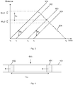
- Figure 3 illustrates the propagation of the pulse pair in the optical fibre and shows distance along the fibre against time.
- Lines 301 and 302 illustrate the leading and trailing edges of the first pulse respectively and lines 303 and 304 the leading and trailing edges of the second pulse respectively.
- the time between t 0 and t 1 therefore corresponds to the duration of the first pulse, i.e. d1.
- the leading edge of the second pulse enters the fibre and at t 3 the trailing edge of the second pulse enters the optical fibre.
- the distributed acoustic sensor of the present invention relies on the fact that any acoustic waves incident on the optical fibre may cause a disturbance, e.g. strain, in the optical fibre which can therefore phase modulate the interference signal generated by the travelling interferometer.
- any phase changes occurring on the optical fibre up to the position of the second section 402 of scattering sites will affect the light from the first section 401 and the second section 402 of fibre equally.
- any phase modulation ⁇ (t) on the section of fibre between the first section 401 and second section 402 will affect the light from the first section 401 only. This can cause a change in phase of the interference signal. Detecting a phase change in the interference signal from a particular section of fibre can thus be used as an indication of an acoustically induced strain upon the optical fibre and hence as an indication of the acoustic waves incident at that section of fibre.
- the pulse configuration is such that the frequency of the first pulse is different to that of the second pulse, i.e. F1 ⁇ F2. This will result in the backscatter interference signal having a component at a carrier frequency equal to the frequency difference between the pulses (
- the carrier frequency is related to the launch rate such that the carrier frequency is less than half the launch rate such that a signal at the carrier frequency can only change in phase by less than 180° between successive launches.
- the launch-to-launch sample rate for each channel is above the Nyquist limit needed to accurately recreate the signal at the carrier frequency.
- pulse pairs are launched into the optical fibre every 50 ⁇ s and the backscatter return signal generated by the pulse pair as it propagates through the fibre is detected.
- the detector output is sampled at a relatively high rate, for instance of the order of 80 - 100 MHz, to detect the backscatter signal from a plurality of different locations within the fibre.
- the random phase variations of the scatter sites lead to a random variation in intensity which destroys the carrier frequency and no useable signal may be detected.
- each pulse pair in the series of pulse pairs has the same frequency configuration, that is a first pulse at a frequency F1 and a second pulse at a frequency F2, then if the backscatter signal from two different pulses pairs was incident on a detector at the same time the backscatter signals would interfere with another at the relevant carrier frequency.
- the launch rate of the pulse pairs may be limited so as to ensure that radiation from only one pulse pair is present in the optical fibre at any one time.
- the time between launches should be sufficient to allow all the radiation from the pulse pair to reach the end of the optical fibre and any radiation reflected or scattered from the end of the optical fibre to be reach the detector before another pulse pair is launched.
- the maximum launch rate of the pulse pairs may therefore be limited by the length of the optical fibre.
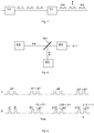
- FIG. 8 illustrates one embodiment of a detector arrangement that could then used to discriminate between the backscatter signals.
- Backscatter light received from the optical fibre is directed toward a polarisation element 801 which, in this example is a polarisation dependent beam splitter.
- This beamsplitter 801 directs light having one polarisation state, say horizontally polarised, to a first detector 802 and light having an orthogonal polarisation state, vertically polarised, to a different detector 803.
- each detector receives light of a single polarisation state only and hence light backscattered from one of the pulse pairs only.
- the signal from each detector can be processed as discussed above to generate a series of phase values from each pulse pair independent of the other pulse pair.
- the pulses of the pulse pair may be at the same frequency as one another.
- F1 F2.
- the pulse pairs are generated such that the phase difference between pulses in the pair vary by a predetermined amount between successive pulse pairs.
- the relative phase of each pulse will be defined with reference to the phase of the first pulse in the series.
- the first pulse of the first pulse pair will be taken to have a relative phase of 0°.
- the second pulse in this first pulse pair will have an arbitrary phase difference, P1, from this first pulse which arises from the arrangement of the optics used to generate the pulses.
- P1 0°.
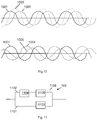
- FIG. 13 shows one possible arrangement where a pulse pair output from intensity modulator 1103 is separated by polarising beam splitter 1301 into horizontally and linearly polarised components into two different channels. Both channels are incident on an EOM 1302 which imposes appropriate phase changes to at least one of the pulses to introduce relative phase differences in successive pulse pairs and the two channels are then recombined so that the pulses are temporally coincident for launching into the optical fibre.
- EOM 1302 which imposes appropriate phase changes to at least one of the pulses to introduce relative phase differences in successive pulse pairs and the two channels are then recombined so that the pulses are temporally coincident for launching into the optical fibre.
- the overall optical power of both pulses should be below the non-linear threshold for the optical fibre and hence, to increase the power available in each pulse the actual pulses may be slightly staggered as illustrated in Figure 12 .
- Figure 14 illustrates a series of pulses being launched at different times and at different wavelengths.
- a first series of pulse pairs may be launched at a first wavelength, ⁇ 1, with a period T 1 between each pulse pair.
- a second series of pulse pairs may also be launched into the optical fibre at a different wavelength, ⁇ 2, with a period T 2 between each pulse pair in this second series and a third series of pulse pairs may also be launched into the optical fibre at a different wavelength again, ⁇ 3, with a period T 3 between each pulse pair.
- the time between launches of the pulses in each series need not be the same, i.e. T 1 may be different to at least one of T 2 and T 3 but in some embodiments the launch rate of at least some of the pulse pairs are the same (i.e. T 1 may be equal to T 2 and/or T 3 ) so that the pulse pairs in the relevant series maintain a certain temporal relationship.
- multiple series of pulse pairs can be used to provide a faster update rate than would be possible using a single pulse pair alone. Additionally however the use of multiple pulse pairs may be used to provide sensing at different spatial resolutions and/or sensitivity.
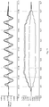
- Figure 15 illustrates three examples of different pulse configurations having pulses of different widths.
- Figure 15 shows the scattering sites within the fibre that would contribute to the instantaneous signal arriving at the detector. In each case the time difference between the start of the first pulse and end of the second pulse is the same.
- the outer edges of the sections of fibre which may contribute to scattering at any instance are located the same distance apart.
- Figure 15 also illustrates (dotted line) an idealised maximum intensity variation in terms of spatial length along the fibre.
- Embodiments of the present invention overcome the problem of fading by using a pulse configuration that comprises temporally separated pulses wherein the gap between the pulses is equal to or greater than the pulse width (of at least the second pulse), i.e. by using a pulse pair of the type illustrated with reference to figures 15b and 15c .
- Figure 18 shows an illustrative curve 1801 of backscatter signal intensity against phase bias position - when the scattering sites define a interferometer with zero phase bias, i.e. the backscatter signals are in phase, the intensity is at a maximum and when the phase bias position is ⁇ 180°, i.e. the signals are out of phase, the intensity is at a minimum.
- Figure 18 also illustrates the noise floor of the sensor.
- the skilled person will appreciate that there will be a certain noise floor, defined by various parameters, which sets the lower signal limit which can reliably be detected. It can be seen that the output signal generated from channel samples acquired at sample time T 2 will mainly be masked by the noise floor.
- a pulse configuration with relatively narrow pulses compared to the gap between pulses may allow a number of different diversity samples to be acquired, each corresponding to substantially independent scattering sites and all of which define portions of fibre which partly overlap.
- a plurality of diversity samples may be acquired which correspond to a plurality of overlapping spatial sensing portions of optical fibre.
- Figure illustrates one implementation of the metric based processing to select the M most self-similar channels.
- the phase value ⁇ and average phase value ⁇ > are received for each channel.
- the metric, M Q is determined for the combination with each other channel to form a matrix 2001 of the metric score .
- the magnitude of metric M Q (A, B) would be the same as that for M Q (B, A).
- the delayed phase value ⁇ d is used in the combination so that the data being combined is the same data from which the metrics were calculated.
- the combination is the sum, for each of the selected channel: ⁇ W i ⁇ d ⁇ ⁇ ⁇ d ⁇ where W i is an optional weighting for ith channel. For instance the weighting W i could be based on the histogram count.
- the embodiments described above use pulse pairs wherein different pulse pairs have different phase encoding in the order to recover a useable phase modulated signal, even within the baseband of the sensor. This avoids the need for very high carrier frequencies and the consequent need for very fast components.
Landscapes
- Physics & Mathematics (AREA)
- General Physics & Mathematics (AREA)
- Optical Transform (AREA)
- Investigating Or Analysing Materials By Optical Means (AREA)
- Length Measuring Devices By Optical Means (AREA)
- Measuring Temperature Or Quantity Of Heat (AREA)
Applications Claiming Priority (4)
| Application Number | Priority Date | Filing Date | Title |
|---|---|---|---|
| GB1106030.8A GB2489749B (en) | 2011-04-08 | 2011-04-08 | Fibre optic distributed sensing |
| GB1111861.9A GB2489760B (en) | 2011-04-08 | 2011-07-11 | Fibre optic distributed sensing |
| PCT/GB2012/050787 WO2012137021A2 (fr) | 2011-04-08 | 2012-04-10 | Détection répartie par fibre optique |
| EP12720938.5A EP2694919B1 (fr) | 2011-04-08 | 2012-04-10 | Détection répartie par fibre optique |
Related Parent Applications (2)
| Application Number | Title | Priority Date | Filing Date |
|---|---|---|---|
| EP12720938.5A Division EP2694919B1 (fr) | 2011-04-08 | 2012-04-10 | Détection répartie par fibre optique |
| EP12720938.5A Division-Into EP2694919B1 (fr) | 2011-04-08 | 2012-04-10 | Détection répartie par fibre optique |
Publications (2)
| Publication Number | Publication Date |
|---|---|
| EP3524940A2 true EP3524940A2 (fr) | 2019-08-14 |
| EP3524940A3 EP3524940A3 (fr) | 2019-11-13 |
Family
ID=44122858
Family Applications (3)
| Application Number | Title | Priority Date | Filing Date |
|---|---|---|---|
| EP12720938.5A Active EP2694919B1 (fr) | 2011-04-08 | 2012-04-10 | Détection répartie par fibre optique |
| EP18194951.2A Withdrawn EP3524940A3 (fr) | 2011-04-08 | 2012-04-10 | Détection distribuée de fibre optique |
| EP12720939.3A Active EP2694924B1 (fr) | 2011-04-08 | 2012-04-10 | Détection répartie par fibre optique |
Family Applications Before (1)
| Application Number | Title | Priority Date | Filing Date |
|---|---|---|---|
| EP12720938.5A Active EP2694919B1 (fr) | 2011-04-08 | 2012-04-10 | Détection répartie par fibre optique |
Family Applications After (1)
| Application Number | Title | Priority Date | Filing Date |
|---|---|---|---|
| EP12720939.3A Active EP2694924B1 (fr) | 2011-04-08 | 2012-04-10 | Détection répartie par fibre optique |
Country Status (8)
| Country | Link |
|---|---|
| US (3) | US9909903B2 (fr) |
| EP (3) | EP2694919B1 (fr) |
| CN (3) | CN103733027B (fr) |
| CA (2) | CA2832365C (fr) |
| ES (1) | ES2879452T3 (fr) |
| GB (2) | GB2489749B (fr) |
| TW (2) | TWI548863B (fr) |
| WO (2) | WO2012137022A2 (fr) |
Cited By (1)
| Publication number | Priority date | Publication date | Assignee | Title |
|---|---|---|---|---|
| CN111609875A (zh) * | 2020-06-10 | 2020-09-01 | 电子科技大学 | 一种基于啁啾连续光的数字域可调分布式光纤传感系统及其传感方法 |
Families Citing this family (109)
| Publication number | Priority date | Publication date | Assignee | Title |
|---|---|---|---|---|
| GB0919906D0 (en) * | 2009-11-13 | 2009-12-30 | Qinetiq Ltd | Improvements to distributed fibre optic sensing |
| GB2489749B (en) * | 2011-04-08 | 2016-01-20 | Optasense Holdings Ltd | Fibre optic distributed sensing |
| US9784862B2 (en) * | 2012-11-30 | 2017-10-10 | Baker Hughes Incorporated | Distributed downhole acousting sensing |
| US10234385B2 (en) * | 2013-03-15 | 2019-03-19 | Ofs Fitel, Llc | Optical sensor having fiduciary marks detected by backscattered light |
| PL2816323T3 (pl) * | 2013-06-18 | 2020-04-30 | Siemens Aktiengesellschaft | Sposób i urządzenie do pomiaru akustycznego otoczenia włókna szklanego |
| GB2515564A (en) * | 2013-06-28 | 2014-12-31 | Optasense Holdings Ltd | Improvements in fibre optic distributed sensing |
| GB2515574A (en) * | 2013-06-28 | 2014-12-31 | Tgs Geophysical Company Ltd | Distributed optical sensing |
| EP2860498B1 (fr) * | 2013-10-09 | 2017-12-06 | Optoplan AS | Traitement de données provenant d'un système de capteur interférométrique à fibre optique réparti |
| US9617847B2 (en) | 2013-10-29 | 2017-04-11 | Halliburton Energy Services, Inc. | Robust optical fiber-based distributed sensing systems and methods |
| GB201319553D0 (en) | 2013-11-05 | 2013-12-18 | Optasense Holdings Ltd | Monitoring of steam injection |
| CA2938526C (fr) | 2014-03-24 | 2019-11-12 | Halliburton Energy Services, Inc. | Outils de puits ayant une telemetrie vibratoire vers une ligne optique a l'interieur de ces derniers |
| GB201405746D0 (en) * | 2014-03-31 | 2014-05-14 | Optasense Holdings Ltd | Downhole surveillance |
| GB201405747D0 (en) | 2014-03-31 | 2014-05-14 | Optasense Holdings Ltd | Downhole surveillance |
| US9702244B2 (en) * | 2014-05-02 | 2017-07-11 | Halliburton Energy Services, Inc. | Distributed acoustic sensing gauge length effect mitigation |
| GB201408132D0 (en) * | 2014-05-08 | 2014-06-25 | Optasense Holdings Ltd | Improvements in fibre optic distributed sensing |
| GB201408131D0 (en) | 2014-05-08 | 2014-06-25 | Optasense Holdings Ltd | Fluid inflow |
| GB201408125D0 (en) * | 2014-05-08 | 2014-06-25 | Optasense Holdings Ltd | Fibre optic distributed sensing |
| CN103954310B (zh) * | 2014-05-22 | 2016-05-25 | 中国人民解放军国防科学技术大学 | 一种干涉型光纤传感器的大动态信号解调装置及解调方法 |
| RU2562689C1 (ru) * | 2014-06-02 | 2015-09-10 | Общество с ограниченной ответственностью "Научно-технический центр Т8" (ООО "Т8 НТЦ") | Распределенный датчик акустических и вибрационных воздействий |
| KR101816675B1 (ko) * | 2014-06-23 | 2018-01-11 | 광주과학기술원 | 인테러게이션 광섬유를 사용한 광특성 측정 장치, 이를 구비하는 광섬유 센서 시스템 및 광특성 측정 방법 |
| JP6535006B2 (ja) * | 2014-08-07 | 2019-06-26 | 古河電気工業株式会社 | 光ファイバセンサ、地震探査方法、石油、天然ガス貯留層分布の計測方法、歪み検知方法および地層の割れ目位置特定方法 |
| GB201414616D0 (en) | 2014-08-18 | 2014-10-01 | Optasense Holdings Ltd | Detection of anomalies in rail wheelsets |
| GB201417836D0 (en) | 2014-10-08 | 2014-11-19 | Optasense Holdings Ltd | Fibre optic cable with transverse sensitivity |
| GB201503861D0 (en) * | 2015-03-06 | 2015-04-22 | Silixa Ltd | Method and apparatus for optical sensing |
| GB201505082D0 (en) | 2015-03-25 | 2015-05-06 | Optasense Holdings Ltd | Detecting failure locations in power cables |
| CN104964698A (zh) * | 2015-04-28 | 2015-10-07 | 南昌航空大学 | 一种用于botdr传感系统的脉冲光信号的产生方法 |
| GB2538282B (en) * | 2015-05-14 | 2018-04-11 | Schlumberger Holdings | Fibre-optic sensing |
| WO2016185223A1 (fr) | 2015-05-20 | 2016-11-24 | Optasense, Inc. | Procédés et appareil d'imagerie microsismique interférométrique |
| WO2016204738A1 (fr) * | 2015-06-17 | 2016-12-22 | Halliburton Energy Services, Inc. | Systèmes de capteurs du niveau du microvolt multiplexés |
| GB2539894B (en) | 2015-06-29 | 2019-03-27 | Optasense Holdings Ltd | Monitoring of power cables |
| GB2554298B (en) | 2015-08-14 | 2021-02-10 | Halliburton Energy Services Inc | Mud pulse detection using distributed acoustic sensing |
| CA2995348C (fr) | 2015-10-19 | 2020-02-25 | Halliburton Energy Services, Inc. | Systemes et procedes de detection acoustique repartie utilisant de multiples largeurs d'impulsion |
| GB201521116D0 (en) | 2015-11-30 | 2016-01-13 | Optasense Holdings Ltd | Tracking using distributed fibre optic sensing |
| AU2016363995B2 (en) | 2015-12-01 | 2021-11-04 | Optasense Inc. | Distributed fibre optic sensing for monitoring rail networks |
| GB201522713D0 (en) | 2015-12-23 | 2016-02-03 | Optasense Holdings Ltd | Determing wellbore properties |
| KR20170086264A (ko) * | 2016-01-18 | 2017-07-26 | 한국전자통신연구원 | Twdm 기반 물리량 측정 장치 및 방법 |
| AU2017246520B2 (en) | 2016-04-07 | 2022-04-07 | Bp Exploration Operating Company Limited | Detecting downhole events using acoustic frequency domain features |
| BR112018070565A2 (pt) | 2016-04-07 | 2019-02-12 | Bp Exploration Operating Company Limited | detecção de eventos de fundo de poço usando características de domínio da frequência acústicas |
| GB201610996D0 (en) * | 2016-06-23 | 2016-08-10 | Optasense Holdings Ltd | Fibre optic sensing |
| GB201611326D0 (en) | 2016-06-29 | 2016-08-10 | Optasense Holdings Ltd | Distributed fibre optic sensing for rail monitoring |
| US10018558B2 (en) * | 2016-08-22 | 2018-07-10 | Nec Corporation | Distributed acoustic sensing in a multicore optical fiber using distributed mode coupling, delay, and simultaneous pulsing with selectable spatial modes |
| US10666337B2 (en) * | 2016-11-11 | 2020-05-26 | Nippon Telegraph And Telephone Corporation | Radio apparatus and radio communication method |
| CN108253999B (zh) * | 2016-12-29 | 2020-06-19 | 中国科学院半导体研究所 | 一种用于分布式光纤声传感系统的降噪方法 |
| GB201701595D0 (en) | 2017-01-31 | 2017-03-15 | Optasense Holdings Ltd | Cable for distributed sensing |
| US11111780B2 (en) * | 2017-02-21 | 2021-09-07 | Halliburton Energy Services, Inc. | Distributed acoustic sensing system with phase modulator for mitigating faded channels |
| GB201703051D0 (en) * | 2017-02-24 | 2017-04-12 | Optasense Holdings Ltd | Monitoring subsea cables |
| GB2560522B (en) | 2017-03-13 | 2022-03-16 | Aiq Dienstleistungen Ug Haftungsbeschraenkt | Dynamic sensitivity distributed acoustic sensing |
| EP3608503B1 (fr) | 2017-03-31 | 2022-05-04 | BP Exploration Operating Company Limited | Surveillance de puits et de surcharge à l'aide de capteurs acoustiques distribués |
| WO2018222097A1 (fr) * | 2017-06-02 | 2018-12-06 | Telefonaktiebolaget Lm Ericsson (Publ) | Nœud de réseau, unité d'émission-réception optique et procédés inclus pour déterminer des informations associées à une fibre optique |
| BR112020003742A2 (pt) | 2017-08-23 | 2020-09-01 | Bp Exploration Operating Company Limited | detecção de localizações de ingresso de areia em fundo de poço |
| CA3078842C (fr) | 2017-10-11 | 2024-01-09 | Bp Exploration Operating Company Limited | Detection d'evenements a l'aide de caracteristiques acoustiques de domaine frequentiel |
| EP3477266B1 (fr) | 2017-10-26 | 2022-03-30 | AiQ Dienstleistungen UG (haftungsbeschränkt) | Dispositif de détection acoustique distribué utilisant différents motifs lumineux d'interrogation cohérents et procédé de détection correspondant |
| CN108303626B (zh) * | 2018-03-09 | 2024-04-12 | 广东电网有限责任公司珠海供电局 | 基于分布式光纤传感阵列的局部放电超声测量系统与方法 |
| CN110501076B (zh) * | 2018-05-16 | 2020-12-25 | 南京理工大学 | 一种基于形状函数的光纤传感器阵列自动时窗定位方法 |
| CN108872154B (zh) * | 2018-05-25 | 2021-01-01 | 中国科学院上海光学精密机械研究所 | 无包层光纤空间角分辨激光散射损耗的测量装置和方法 |
| CN109210385B (zh) * | 2018-06-08 | 2020-10-20 | 王超凡 | 一种基于Phase-OTDR的分布式光纤传感系统及方法 |
| EP3581091A1 (fr) * | 2018-06-12 | 2019-12-18 | Koninklijke Philips N.V. | Système et procédé permettant de déterminer au moins un signe vital d'une personne |
| JP6814180B2 (ja) * | 2018-07-02 | 2021-01-13 | 日本電信電話株式会社 | 分布光ファイバ振動計測装置および分布光ファイバ振動計測方法 |
| GB201814159D0 (en) | 2018-08-31 | 2018-10-17 | Optasense Holdings Ltd | Fibre optic apparatus |
| GB201814891D0 (en) | 2018-09-13 | 2018-10-31 | Optasense Holdings Ltd | Fibre optic cables |
| US20200174149A1 (en) | 2018-11-29 | 2020-06-04 | Bp Exploration Operating Company Limited | Event Detection Using DAS Features with Machine Learning |
| CA3109762C (fr) * | 2018-12-07 | 2023-08-22 | Halliburton Energy Services, Inc. | Acquisition simultanee de detection acoustique distribuee destinee a la surveillance |
| GB201820331D0 (en) | 2018-12-13 | 2019-01-30 | Bp Exploration Operating Co Ltd | Distributed acoustic sensing autocalibration |
| WO2020119915A1 (fr) * | 2018-12-14 | 2020-06-18 | Omnisens Sa | Procédé et dispositif de mesure de quantité physique basée sur la rétrodiffusion de rayleigh |
| CA3124638C (fr) * | 2019-01-25 | 2024-05-14 | Halliburton Energy Services, Inc. | Detection de phase a detection d'erreur de difference de capteur redondante et correction intelligente |
| EP3712577B1 (fr) * | 2019-03-22 | 2023-07-26 | ABB Schweiz AG | Appareil de surveillance d'équipements |
| US11378443B2 (en) * | 2019-05-22 | 2022-07-05 | Nec Corporation | Performance of Rayleigh-based phase-OTDR with correlation-based diversity combining and bias removal |
| CN110207803B (zh) * | 2019-06-21 | 2020-07-10 | 华中科技大学 | 一种基于可变积分窗的分布式光纤传感增益提升方法 |
| CN110375841B (zh) * | 2019-07-25 | 2024-01-23 | 上海交通大学 | 基于分布式光纤声波传感系统的振动传感方法 |
| CN110595599B (zh) * | 2019-08-15 | 2021-05-28 | 广东电网有限责任公司 | 减少光纤振动系统偏振衰落的方法及应用其的探测系统 |
| MY197170A (en) * | 2019-09-13 | 2023-05-28 | Petroliam Nasional Berhad Petronas | Optical fiber distribution measurement system and signal processing method for optical fiber distribution measurement |
| WO2021052602A1 (fr) | 2019-09-20 | 2021-03-25 | Lytt Limited | Systèmes et procédés de prédiction d'entrée de sable pour puits de forage souterrains |
| US11977195B2 (en) * | 2019-09-20 | 2024-05-07 | Halliburton Energy Services, Inc. | Triggering distributed acoustic sensing downhole using an active fiber stretcher assembly |
| GB2588177B (en) * | 2019-10-11 | 2022-10-12 | Sintela Ltd | Signal processing methods for an optical detection system |
| CA3154435C (fr) | 2019-10-17 | 2023-03-28 | Lytt Limited | Detection d'ecoulement entrant en utilisant de caracteristiques dts |
| EP4045766A1 (fr) | 2019-10-17 | 2022-08-24 | Lytt Limited | Caractérisation de débits entrants de fluide au moyen de mesures de das/dts hybrides |
| US11455294B2 (en) * | 2019-10-18 | 2022-09-27 | Sap Se | Information lifecycle management notification framework |
| US20220397451A1 (en) * | 2019-10-29 | 2022-12-15 | Nec Corporation | Acoustic sensor |
| WO2021093974A1 (fr) | 2019-11-15 | 2021-05-20 | Lytt Limited | Systèmes et procédés d'améliorations du rabattement dans des puits |
| CN113218494A (zh) * | 2020-01-21 | 2021-08-06 | 中国科学院上海光学精密机械研究所 | 一种分布式光纤声传感系统及信号处理方法 |
| GB202003892D0 (en) | 2020-03-18 | 2020-05-06 | Optasense Holdings Ltd | Fibre optic cable and sensing apparatus |
| US11747133B2 (en) * | 2020-04-28 | 2023-09-05 | Board Of Trustees Of Michigan State University | Demodulation of fiber optic interferometric sensors |
| US12605083B2 (en) * | 2020-05-01 | 2026-04-21 | Viavi Solutions Inc. | Optical sensor device |
| US20210348971A1 (en) * | 2020-05-07 | 2021-11-11 | Ut-Battelle, Llc | Post-processing method to extend the functional range of optical backscatter reflectometry in extreme environments |
| US20210356317A1 (en) * | 2020-05-18 | 2021-11-18 | Nec Laboratories America, Inc | Complex and phase domain vibration strength estimation for coherent distributed acoustic sensing |
| US11543287B2 (en) * | 2020-05-20 | 2023-01-03 | Nec Corporation | Distributed acoustic sensing using multi-band time-gated digital orthogonal frequency domain reflectometry |
| WO2021249643A1 (fr) | 2020-06-11 | 2021-12-16 | Lytt Limited | Systèmes et procédés de caractérisation de flux de fluide souterrain |
| CA3182376A1 (fr) | 2020-06-18 | 2021-12-23 | Cagri CERRAHOGLU | Formation de modele d'evenement a l'aide de donnees in situ |
| WO2021254633A1 (fr) | 2020-06-18 | 2021-12-23 | Lytt Limited | Formation de modèle d'événement à l'aide de données in situ |
| CN111982189B (zh) * | 2020-07-29 | 2022-04-29 | 电子科技大学 | 基于光子探测技术同时实现温度与应变的高精度传感方法 |
| GB202012154D0 (en) | 2020-08-05 | 2020-09-16 | Optasense Holdings Ltd | Distributed fibre optic sensing |
| CN116194740B (zh) * | 2020-08-26 | 2025-07-25 | 日本电信电话株式会社 | 振动分布测量装置及其方法 |
| GB202020409D0 (en) | 2020-12-22 | 2021-02-03 | Optasense Holdings Ltd | Fibre optic sensing |
| US20220283330A1 (en) * | 2021-03-03 | 2022-09-08 | Halliburton Energy Services, Inc. | Gauge Length Correction For Seismic Attenuation From Distributed Acoustic System Fiber Optic Data |
| CN113008310B (zh) * | 2021-04-02 | 2025-06-06 | 广西师范大学 | 瑞利-拉曼融合型分布式光纤传感系统和数据处理方法 |
| GB202106046D0 (en) * | 2021-04-28 | 2021-06-09 | Optasense Holdings Ltd | Fibre optic sensing |
| WO2022238677A1 (fr) | 2021-05-11 | 2022-11-17 | Optasense Holdings Limited | Détection par fibres optiques |
| GB2609641B (en) * | 2021-08-11 | 2024-10-02 | Sintela Ltd | Signal processing methods for an optical detection system |
| CN114184276B (zh) * | 2021-11-05 | 2025-03-14 | 深圳华迈兴微医疗科技有限公司 | 一种基于光纤的多通道采光方法及装置 |
| CN114485900B (zh) * | 2021-12-31 | 2023-10-03 | 武汉光谷互连科技有限公司 | 直接探测分布式声波传感系统的无衰落解调方法 |
| CN114353970B (zh) * | 2022-01-12 | 2024-03-29 | 中国人民解放军国防科技大学 | 用于光纤干涉仪多相检测的初相位调制方法及调制装置 |
| GB202201225D0 (en) | 2022-01-31 | 2022-03-16 | Optasense Holdings Ltd | Fibre optic cables for sensing |
| US11824667B2 (en) * | 2022-09-06 | 2023-11-21 | Ultralogic 6G Llc | Waveform indicators for fault localization in 5G and 6G messages |
| CN115479659B (zh) * | 2022-09-14 | 2025-05-13 | 武汉理工光科股份有限公司 | 一种基于fpga的光纤振动解调装置和方法 |
| GB202218511D0 (en) * | 2022-12-08 | 2023-01-25 | Microsoft Technology Licensing Llc | Media slice tracking in a communications network |
| US20240344878A1 (en) * | 2023-04-11 | 2024-10-17 | Exfo Inc. | Method and apparatus of distributed acoustic sensing |
| CN116989832B (zh) * | 2023-09-26 | 2023-12-26 | 北京大学 | 一种可变多空间传感尺度地震勘探方法及系统 |
| CN117030000B (zh) * | 2023-10-10 | 2024-01-12 | 之江实验室 | 一种分布式声波传感偏振控制系统及偏振衰落抑制方法 |
| EP4563947A1 (fr) * | 2023-11-30 | 2025-06-04 | BAE SYSTEMS plc | Détection distribuée par fibre optique |
Family Cites Families (33)
| Publication number | Priority date | Publication date | Assignee | Title |
|---|---|---|---|---|
| US2005504A (en) * | 1934-02-10 | 1935-06-18 | Prautzsch Richard | Pump for automatic, periodically working gas analyzers |
| HU181160B (en) | 1980-07-25 | 1983-06-28 | Egyt Gyogyszervegyeszeti Gyar | Process for preparing derivatives of pyridazino/4,5-b/quinoxaline-5,10-dioxide |
| DE3129308A1 (de) * | 1981-07-24 | 1983-02-10 | Hoke, Manfried, Prof. Dr., 4400 Münster | "verfahren und vorrichtung zur automatischen auswertung von stoerueberlagerten messwerten" |
| GB2207236B (en) | 1987-07-21 | 1991-04-24 | Plessey Co Plc | Improvements relating to optical fibre sensing arrangements |
| GB2219902B (en) | 1988-06-14 | 1992-01-22 | Plessey Co Plc | Optical sensing systems |
| GB2222247A (en) * | 1988-08-23 | 1990-02-28 | Plessey Co Plc | Distributed fibre optic sensor system |
| US5194847A (en) | 1991-07-29 | 1993-03-16 | Texas A & M University System | Apparatus and method for fiber optic intrusion sensing |
| KR0133488B1 (en) * | 1993-01-06 | 1998-04-23 | Toshiba Kk | Temperature distribution detector using optical fiber |
| WO2004073172A2 (fr) * | 2003-02-12 | 2004-08-26 | Sensornet Limited | Procede et dispositif de production et d'emission d'impulsions optiques de haute energie pour mesures de grandes distances |
| US7081959B2 (en) | 2003-08-27 | 2006-07-25 | Optoplan As | Method and apparatus for providing polarization insensitive signal processing for interferometric sensors |
| GB0424305D0 (en) | 2004-11-03 | 2004-12-01 | Polarmetrix Ltd | Phase-disturbance location and measurement in optical-fibre interferometric reflectometry |
| US7107177B2 (en) | 2005-02-14 | 2006-09-12 | International Business Machines Corporation | Combining multiple reference measurement collections into a weighted reference measurement collection |
| EP1729096A1 (fr) | 2005-06-02 | 2006-12-06 | BRITISH TELECOMMUNICATIONS public limited company | Méthode et dispositif de détermination de la position d'une perturbation dans une fibre optique |
| GB0521713D0 (en) * | 2005-10-25 | 2005-11-30 | Qinetiq Ltd | Traffic sensing and monitoring apparatus |
| GB2441154B (en) * | 2006-08-24 | 2009-02-18 | Schlumberger Holdings | Measuring brillouin backscatter from an optical fibre using channelisation |
| GB2442745B (en) * | 2006-10-13 | 2011-04-06 | At & T Corp | Method and apparatus for acoustic sensing using multiple optical pulses |
| GB2442746B (en) | 2006-10-13 | 2011-04-06 | At & T Corp | Method and apparatus for acoustic sensing using multiple optical pulses |
| GB2445364B (en) * | 2006-12-29 | 2010-02-17 | Schlumberger Holdings | Fault-tolerant distributed fiber optic intrusion detection |
| GB0705240D0 (en) * | 2007-03-14 | 2007-04-25 | Qinetiq Ltd | Phase based sensing |
| US7916303B2 (en) | 2007-11-13 | 2011-03-29 | Optoplan As | Non-uniform sampling to extend dynamic range of interferometric sensors |
| US7605744B1 (en) * | 2008-06-03 | 2009-10-20 | Vaisala Oyj | Method for extension of unambiguous range and velocity of a weather radar |
| US7859654B2 (en) | 2008-07-17 | 2010-12-28 | Schlumberger Technology Corporation | Frequency-scanned optical time domain reflectometry |
| GB0815523D0 (en) * | 2008-08-27 | 2008-10-01 | Qinetiq Ltd | Phase based sensing |
| GB0823306D0 (en) | 2008-12-22 | 2009-01-28 | Rogers Alan | Frequency-mapped distributed presure measurement |
| CN101539631B (zh) | 2009-04-30 | 2011-11-30 | 华中科技大学 | 一种地震监测装置 |
| CN105910633B (zh) | 2009-05-27 | 2019-10-29 | 希里克萨有限公司 | 光学传感器及使用方法 |
| US8131121B2 (en) * | 2009-07-07 | 2012-03-06 | At&T Intellectual Property I, L.P. | Optical fiber pipeline monitoring system and method |
| GB0917150D0 (en) * | 2009-09-30 | 2009-11-11 | Qinetiq Ltd | Phase based sensing |
| GB0921062D0 (en) * | 2009-12-02 | 2010-01-13 | Qinetiq Ltd | Phased based sensing |
| US8605542B2 (en) * | 2010-05-26 | 2013-12-10 | Schlumberger Technology Corporation | Detection of seismic signals using fiber optic distributed sensors |
| US9476760B2 (en) * | 2010-06-25 | 2016-10-25 | Schlumberger Technology Corporation | Precision measurements in a fiber optic distributed sensor system |
| GB201019117D0 (en) * | 2010-11-11 | 2010-12-29 | Fotech Solutions Ltd | Distributed optical fibre sensor |
| GB2489749B (en) | 2011-04-08 | 2016-01-20 | Optasense Holdings Ltd | Fibre optic distributed sensing |
-
2011
- 2011-04-08 GB GB1106030.8A patent/GB2489749B/en active Active
- 2011-07-11 GB GB1111861.9A patent/GB2489760B/en active Active
-
2012
- 2012-04-06 TW TW101112141A patent/TWI548863B/zh not_active IP Right Cessation
- 2012-04-06 US US13/441,802 patent/US9909903B2/en active Active
- 2012-04-06 US US13/441,798 patent/US9435668B2/en active Active
- 2012-04-06 TW TW101112142A patent/TWI582393B/zh not_active IP Right Cessation
- 2012-04-10 EP EP12720938.5A patent/EP2694919B1/fr active Active
- 2012-04-10 CA CA2832365A patent/CA2832365C/fr active Active
- 2012-04-10 WO PCT/GB2012/050788 patent/WO2012137022A2/fr not_active Ceased
- 2012-04-10 CN CN201280027632.6A patent/CN103733027B/zh active Active
- 2012-04-10 CA CA2832362A patent/CA2832362C/fr active Active
- 2012-04-10 CN CN201280027631.1A patent/CN103635782B/zh active Active
- 2012-04-10 EP EP18194951.2A patent/EP3524940A3/fr not_active Withdrawn
- 2012-04-10 CN CN201710675604.XA patent/CN107515019B/zh active Active
- 2012-04-10 ES ES12720939T patent/ES2879452T3/es active Active
- 2012-04-10 EP EP12720939.3A patent/EP2694924B1/fr active Active
- 2012-04-10 WO PCT/GB2012/050787 patent/WO2012137021A2/fr not_active Ceased
-
2016
- 2016-09-06 US US15/257,188 patent/US9945717B2/en active Active
Cited By (2)
| Publication number | Priority date | Publication date | Assignee | Title |
|---|---|---|---|---|
| CN111609875A (zh) * | 2020-06-10 | 2020-09-01 | 电子科技大学 | 一种基于啁啾连续光的数字域可调分布式光纤传感系统及其传感方法 |
| CN111609875B (zh) * | 2020-06-10 | 2021-12-28 | 电子科技大学 | 基于啁啾连续光的数字域可调分布式光纤传感系统及方法 |
Also Published As
Similar Documents
| Publication | Publication Date | Title |
|---|---|---|
| EP2694919B1 (fr) | Détection répartie par fibre optique | |
| EP3140619B1 (fr) | Améliorations apportées à une détection distribuée par fibres optiques | |
| AU2015257489B2 (en) | Fibre optic distributed sensing | |
| US8923663B2 (en) | Distributed fibre optic sensing | |
| WO2015170116A1 (fr) | Améliorations dans la détection distribuée par fibre optique | |
| Iida et al. | High-frequency distributed acoustic sensing faster than repetition limit with frequency-multiplexed phase-OTDR | |
| GB2618376A (en) | Fibre optic sensing |
Legal Events
| Date | Code | Title | Description |
|---|---|---|---|
| PUAI | Public reference made under article 153(3) epc to a published international application that has entered the european phase |
Free format text: ORIGINAL CODE: 0009012 |
|
| STAA | Information on the status of an ep patent application or granted ep patent |
Free format text: STATUS: THE APPLICATION HAS BEEN PUBLISHED |
|
| AC | Divisional application: reference to earlier application |
Ref document number: 2694919 Country of ref document: EP Kind code of ref document: P |
|
| AK | Designated contracting states |
Kind code of ref document: A2 Designated state(s): AL AT BE BG CH CY CZ DE DK EE ES FI FR GB GR HR HU IE IS IT LI LT LU LV MC MK MT NL NO PL PT RO RS SE SI SK SM TR |
|
| PUAL | Search report despatched |
Free format text: ORIGINAL CODE: 0009013 |
|
| AK | Designated contracting states |
Kind code of ref document: A3 Designated state(s): AL AT BE BG CH CY CZ DE DK EE ES FI FR GB GR HR HU IE IS IT LI LT LU LV MC MK MT NL NO PL PT RO RS SE SI SK SM TR |
|
| RIC1 | Information provided on ipc code assigned before grant |
Ipc: G01D 5/353 20060101AFI20191008BHEP |
|
| STAA | Information on the status of an ep patent application or granted ep patent |
Free format text: STATUS: REQUEST FOR EXAMINATION WAS MADE |
|
| 17P | Request for examination filed |
Effective date: 20200512 |
|
| RBV | Designated contracting states (corrected) |
Designated state(s): AL AT BE BG CH CY CZ DE DK EE ES FI FR GB GR HR HU IE IS IT LI LT LU LV MC MK MT NL NO PL PT RO RS SE SI SK SM TR |
|
| STAA | Information on the status of an ep patent application or granted ep patent |
Free format text: STATUS: EXAMINATION IS IN PROGRESS |
|
| 17Q | First examination report despatched |
Effective date: 20201008 |
|
| STAA | Information on the status of an ep patent application or granted ep patent |
Free format text: STATUS: THE APPLICATION IS DEEMED TO BE WITHDRAWN |
|
| 18D | Application deemed to be withdrawn |
Effective date: 20210219 |