EP3524977A1 - Dispositif de séparation de plasma et procédé de séparation de plasma - Google Patents
Dispositif de séparation de plasma et procédé de séparation de plasma Download PDFInfo
- Publication number
- EP3524977A1 EP3524977A1 EP17858007.2A EP17858007A EP3524977A1 EP 3524977 A1 EP3524977 A1 EP 3524977A1 EP 17858007 A EP17858007 A EP 17858007A EP 3524977 A1 EP3524977 A1 EP 3524977A1
- Authority
- EP
- European Patent Office
- Prior art keywords
- blood
- plasma
- separation
- collection
- separation member
- Prior art date
- Legal status (The legal status is an assumption and is not a legal conclusion. Google has not performed a legal analysis and makes no representation as to the accuracy of the status listed.)
- Withdrawn
Links
- 238000000926 separation method Methods 0.000 title claims abstract description 414
- 210000004369 blood Anatomy 0.000 claims abstract description 572
- 239000008280 blood Substances 0.000 claims abstract description 572
- NJPPVKZQTLUDBO-UHFFFAOYSA-N novaluron Chemical compound C1=C(Cl)C(OC(F)(F)C(OC(F)(F)F)F)=CC=C1NC(=O)NC(=O)C1=C(F)C=CC=C1F NJPPVKZQTLUDBO-UHFFFAOYSA-N 0.000 claims abstract description 36
- 230000002209 hydrophobic effect Effects 0.000 claims abstract description 24
- 230000003247 decreasing effect Effects 0.000 claims abstract description 22
- 238000005520 cutting process Methods 0.000 claims description 72
- 238000004159 blood analysis Methods 0.000 claims description 14
- 210000002966 serum Anatomy 0.000 abstract description 41
- 210000002381 plasma Anatomy 0.000 description 371
- 239000000306 component Substances 0.000 description 42
- 239000000463 material Substances 0.000 description 41
- 238000002474 experimental method Methods 0.000 description 40
- 230000000694 effects Effects 0.000 description 32
- 239000007788 liquid Substances 0.000 description 31
- 238000000034 method Methods 0.000 description 31
- 230000001413 cellular effect Effects 0.000 description 20
- 230000002123 temporal effect Effects 0.000 description 20
- 239000000853 adhesive Substances 0.000 description 16
- 230000001070 adhesive effect Effects 0.000 description 16
- 239000011521 glass Substances 0.000 description 13
- 206010018910 Haemolysis Diseases 0.000 description 11
- 230000008588 hemolysis Effects 0.000 description 11
- 210000000601 blood cell Anatomy 0.000 description 10
- 210000003743 erythrocyte Anatomy 0.000 description 10
- 238000004891 communication Methods 0.000 description 9
- 210000000265 leukocyte Anatomy 0.000 description 9
- 239000004417 polycarbonate Substances 0.000 description 9
- 239000011248 coating agent Substances 0.000 description 8
- 208000007536 Thrombosis Diseases 0.000 description 7
- 239000003146 anticoagulant agent Substances 0.000 description 7
- 229940127219 anticoagulant drug Drugs 0.000 description 7
- 239000012503 blood component Substances 0.000 description 7
- 238000000576 coating method Methods 0.000 description 6
- 230000000052 comparative effect Effects 0.000 description 6
- 239000004743 Polypropylene Substances 0.000 description 5
- 239000004793 Polystyrene Substances 0.000 description 5
- 239000000835 fiber Substances 0.000 description 5
- 230000005484 gravity Effects 0.000 description 5
- -1 polyethylene Polymers 0.000 description 5
- 229920000139 polyethylene terephthalate Polymers 0.000 description 5
- 239000005020 polyethylene terephthalate Substances 0.000 description 5
- 239000011347 resin Substances 0.000 description 5
- 229920005989 resin Polymers 0.000 description 5
- 239000011159 matrix material Substances 0.000 description 4
- 229920000515 polycarbonate Polymers 0.000 description 4
- 239000004800 polyvinyl chloride Substances 0.000 description 4
- 229920000915 polyvinyl chloride Polymers 0.000 description 4
- 239000000126 substance Substances 0.000 description 4
- 238000012549 training Methods 0.000 description 4
- 229920000122 acrylonitrile butadiene styrene Polymers 0.000 description 3
- 230000001154 acute effect Effects 0.000 description 3
- 238000004458 analytical method Methods 0.000 description 3
- 210000001772 blood platelet Anatomy 0.000 description 3
- 238000010241 blood sampling Methods 0.000 description 3
- 238000005345 coagulation Methods 0.000 description 3
- 230000015271 coagulation Effects 0.000 description 3
- 238000012937 correction Methods 0.000 description 3
- 230000005661 hydrophobic surface Effects 0.000 description 3
- 101100008044 Caenorhabditis elegans cut-1 gene Proteins 0.000 description 2
- 102000008946 Fibrinogen Human genes 0.000 description 2
- 108010049003 Fibrinogen Proteins 0.000 description 2
- 239000002390 adhesive tape Substances 0.000 description 2
- 239000011230 binding agent Substances 0.000 description 2
- 230000017531 blood circulation Effects 0.000 description 2
- 210000001124 body fluid Anatomy 0.000 description 2
- 239000000701 coagulant Substances 0.000 description 2
- 239000002360 explosive Substances 0.000 description 2
- 229940012952 fibrinogen Drugs 0.000 description 2
- 239000003365 glass fiber Substances 0.000 description 2
- 230000036541 health Effects 0.000 description 2
- 230000007246 mechanism Effects 0.000 description 2
- 238000012986 modification Methods 0.000 description 2
- 230000004048 modification Effects 0.000 description 2
- 238000000465 moulding Methods 0.000 description 2
- 239000004745 nonwoven fabric Substances 0.000 description 2
- 229920001155 polypropylene Polymers 0.000 description 2
- 229920001296 polysiloxane Polymers 0.000 description 2
- 229920002223 polystyrene Polymers 0.000 description 2
- 238000002360 preparation method Methods 0.000 description 2
- 230000008569 process Effects 0.000 description 2
- 238000007493 shaping process Methods 0.000 description 2
- 229910052710 silicon Inorganic materials 0.000 description 2
- 239000010703 silicon Substances 0.000 description 2
- 239000007787 solid Substances 0.000 description 2
- 230000002269 spontaneous effect Effects 0.000 description 2
- 238000004381 surface treatment Methods 0.000 description 2
- 229920001059 synthetic polymer Polymers 0.000 description 2
- XLYOFNOQVPJJNP-UHFFFAOYSA-N water Substances O XLYOFNOQVPJJNP-UHFFFAOYSA-N 0.000 description 2
- 102000004506 Blood Proteins Human genes 0.000 description 1
- 108010017384 Blood Proteins Proteins 0.000 description 1
- 102000004190 Enzymes Human genes 0.000 description 1
- 108090000790 Enzymes Proteins 0.000 description 1
- 102000009123 Fibrin Human genes 0.000 description 1
- 108010073385 Fibrin Proteins 0.000 description 1
- BWGVNKXGVNDBDI-UHFFFAOYSA-N Fibrin monomer Chemical compound CNC(=O)CNC(=O)CN BWGVNKXGVNDBDI-UHFFFAOYSA-N 0.000 description 1
- 238000006424 Flood reaction Methods 0.000 description 1
- YCKRFDGAMUMZLT-UHFFFAOYSA-N Fluorine atom Chemical compound [F] YCKRFDGAMUMZLT-UHFFFAOYSA-N 0.000 description 1
- 102000001554 Hemoglobins Human genes 0.000 description 1
- 108010054147 Hemoglobins Proteins 0.000 description 1
- 239000004698 Polyethylene Substances 0.000 description 1
- 239000004721 Polyphenylene oxide Substances 0.000 description 1
- 239000004372 Polyvinyl alcohol Substances 0.000 description 1
- 229920006362 Teflon® Polymers 0.000 description 1
- 230000009471 action Effects 0.000 description 1
- 238000013375 chromatographic separation Methods 0.000 description 1
- 239000000470 constituent Substances 0.000 description 1
- 238000007796 conventional method Methods 0.000 description 1
- 238000013461 design Methods 0.000 description 1
- 239000004205 dimethyl polysiloxane Substances 0.000 description 1
- 235000013870 dimethyl polysiloxane Nutrition 0.000 description 1
- 201000010099 disease Diseases 0.000 description 1
- 208000037265 diseases, disorders, signs and symptoms Diseases 0.000 description 1
- 229940079593 drug Drugs 0.000 description 1
- 239000003814 drug Substances 0.000 description 1
- 238000005516 engineering process Methods 0.000 description 1
- 229950003499 fibrin Drugs 0.000 description 1
- 238000011049 filling Methods 0.000 description 1
- 239000011737 fluorine Substances 0.000 description 1
- 229910052731 fluorine Inorganic materials 0.000 description 1
- 230000005182 global health Effects 0.000 description 1
- 210000003714 granulocyte Anatomy 0.000 description 1
- 229920001477 hydrophilic polymer Polymers 0.000 description 1
- 230000005660 hydrophilic surface Effects 0.000 description 1
- 210000002865 immune cell Anatomy 0.000 description 1
- 230000008595 infiltration Effects 0.000 description 1
- 238000001764 infiltration Methods 0.000 description 1
- 229910052500 inorganic mineral Inorganic materials 0.000 description 1
- 238000003780 insertion Methods 0.000 description 1
- 230000037431 insertion Effects 0.000 description 1
- 238000007689 inspection Methods 0.000 description 1
- 238000011835 investigation Methods 0.000 description 1
- 239000000314 lubricant Substances 0.000 description 1
- 210000004698 lymphocyte Anatomy 0.000 description 1
- 238000004519 manufacturing process Methods 0.000 description 1
- 239000011707 mineral Substances 0.000 description 1
- 238000002156 mixing Methods 0.000 description 1
- 239000000203 mixture Substances 0.000 description 1
- 210000002433 mononuclear leukocyte Anatomy 0.000 description 1
- 229920005615 natural polymer Polymers 0.000 description 1
- 210000000056 organ Anatomy 0.000 description 1
- 239000012994 photoredox catalyst Substances 0.000 description 1
- 239000000049 pigment Substances 0.000 description 1
- 210000004180 plasmocyte Anatomy 0.000 description 1
- 229920000435 poly(dimethylsiloxane) Polymers 0.000 description 1
- 229920000570 polyether Polymers 0.000 description 1
- 229920000573 polyethylene Polymers 0.000 description 1
- 229920002451 polyvinyl alcohol Polymers 0.000 description 1
- 229920000036 polyvinylpyrrolidone Polymers 0.000 description 1
- 239000001267 polyvinylpyrrolidone Substances 0.000 description 1
- 235000013855 polyvinylpyrrolidone Nutrition 0.000 description 1
- 230000002265 prevention Effects 0.000 description 1
- 150000003839 salts Chemical class 0.000 description 1
- 238000005070 sampling Methods 0.000 description 1
- 238000007789 sealing Methods 0.000 description 1
- 238000004544 sputter deposition Methods 0.000 description 1
- 239000012756 surface treatment agent Substances 0.000 description 1
- 239000004094 surface-active agent Substances 0.000 description 1
- 229920002994 synthetic fiber Polymers 0.000 description 1
- 238000011144 upstream manufacturing Methods 0.000 description 1
- 238000003828 vacuum filtration Methods 0.000 description 1
- 238000009423 ventilation Methods 0.000 description 1
Images


Classifications
-
- G—PHYSICS
- G01—MEASURING; TESTING
- G01N—INVESTIGATING OR ANALYSING MATERIALS BY DETERMINING THEIR CHEMICAL OR PHYSICAL PROPERTIES
- G01N33/00—Investigating or analysing materials by specific methods not covered by groups G01N1/00 - G01N31/00
- G01N33/48—Biological material, e.g. blood, urine; Haemocytometers
- G01N33/483—Physical analysis of biological material
- G01N33/487—Physical analysis of biological material of liquid biological material
- G01N33/49—Blood
- G01N33/491—Blood by separating the blood components
-
- A—HUMAN NECESSITIES
- A61—MEDICAL OR VETERINARY SCIENCE; HYGIENE
- A61B—DIAGNOSIS; SURGERY; IDENTIFICATION
- A61B5/00—Measuring for diagnostic purposes; Identification of persons
- A61B5/15—Devices for taking samples of blood
- A61B5/150007—Details
- A61B5/150755—Blood sample preparation for further analysis, e.g. by separating blood components or by mixing
-
- B—PERFORMING OPERATIONS; TRANSPORTING
- B01—PHYSICAL OR CHEMICAL PROCESSES OR APPARATUS IN GENERAL
- B01L—CHEMICAL OR PHYSICAL LABORATORY APPARATUS FOR GENERAL USE
- B01L3/00—Containers or dishes for laboratory use, e.g. laboratory glassware; Droppers
- B01L3/50—Containers for the purpose of retaining a material to be analysed, e.g. test tubes
- B01L3/502—Containers for the purpose of retaining a material to be analysed, e.g. test tubes with fluid transport, e.g. in multi-compartment structures
- B01L3/5027—Containers for the purpose of retaining a material to be analysed, e.g. test tubes with fluid transport, e.g. in multi-compartment structures by integrated microfluidic structures, i.e. dimensions of channels and chambers are such that surface tension forces are important, e.g. lab-on-a-chip
-
- G—PHYSICS
- G01—MEASURING; TESTING
- G01N—INVESTIGATING OR ANALYSING MATERIALS BY DETERMINING THEIR CHEMICAL OR PHYSICAL PROPERTIES
- G01N1/00—Sampling; Preparing specimens for investigation
- G01N1/02—Devices for withdrawing samples
- G01N1/10—Devices for withdrawing samples in the liquid or fluent state
-
- G—PHYSICS
- G01—MEASURING; TESTING
- G01N—INVESTIGATING OR ANALYSING MATERIALS BY DETERMINING THEIR CHEMICAL OR PHYSICAL PROPERTIES
- G01N33/00—Investigating or analysing materials by specific methods not covered by groups G01N1/00 - G01N31/00
- G01N33/48—Biological material, e.g. blood, urine; Haemocytometers
-
- A—HUMAN NECESSITIES
- A61—MEDICAL OR VETERINARY SCIENCE; HYGIENE
- A61B—DIAGNOSIS; SURGERY; IDENTIFICATION
- A61B5/00—Measuring for diagnostic purposes; Identification of persons
- A61B5/15—Devices for taking samples of blood
- A61B5/150007—Details
- A61B5/150358—Strips for collecting blood, e.g. absorbent
-
- B—PERFORMING OPERATIONS; TRANSPORTING
- B01—PHYSICAL OR CHEMICAL PROCESSES OR APPARATUS IN GENERAL
- B01L—CHEMICAL OR PHYSICAL LABORATORY APPARATUS FOR GENERAL USE
- B01L2300/00—Additional constructional details
- B01L2300/16—Surface properties and coatings
- B01L2300/161—Control and use of surface tension forces, e.g. hydrophobic, hydrophilic
- B01L2300/165—Specific details about hydrophobic, oleophobic surfaces
Definitions
- the present invention relates to an apparatus and method for separating a liquid component from a bodily fluid or blood, especially for separating plasma (or serum) from blood. More particularly, the invention relates to a plasma (or serum) separation apparatus and a plasma (or serum) separation method which do not require a centrifuge, or a suctioning or pressurizing pump, or the like, yet are capable of simply and conveniently separating plasma (or serum) even from a minute amount of blood, at a low cost.
- Medical diagnose through blood examination is routinely conducted because various clinical statuses of patient can be determined based on absence or presence and/or the concentration values of certain substances dissolved in the bodily fluid of patient, especially blood.
- a blood sample especially plasma or serum
- a blood examination can be used to determine physiological and biochemical statuses of the patient in relation to a disease, such as mineral or certain DNA contents, drug potency, and organ functions.
- a disease such as mineral or certain DNA contents, drug potency, and organ functions.
- Such blood examination can be generally available in a clinical laboratory in a hospital, clinical examination company, and the like.
- those samples to be examined namely, plasma and serum
- serum are similar to each other in their components, except that serum obtained from a coagulated blood specimen is free of fibrinogen and other certain coagulant factors lost as a result of coagulation process.
- a medical practitioner or the like collects about 10 mL of venous blood using a syringe, thereafter it is sent to an examination facility, where a centrifugal separation method is carried out for regulation and separation of a liquid component, such as plasma or serum, from blood cells or blood clots.
- a centrifugal separation method for separating blood into cellular components (e.g., red blood cells and white blood cells) and blood clots, and plasma or serum, by the difference of specific gravities.
- centrifugal separation method in general, when no hemolysis has occurred and when an anticoagulant has been added, blood components are clearly separated in a centrifugal tube such that red blood cells having a heavy specific gravity would be separated to a lower layer (about 41% of whole blood), plasma having a light specific gravity would be separated to a upper layer (about 55% of whole blood), and platelets and white blood cells would be separated to a middle layer (about 4% of whole blood) .
- whole blood is separated into serum at the upper layer and blood clots at the lower layer through a centrifugal operation.
- blood collection is a practice to be performed by a medical worker, it can impose a burden on both an objective person (i.e., the subject) and medical establishments, and can also increase costs. Furthermore, blood examination will require a centrifuge separator and operating staff therefor, taking an additional cost and labor.
- plasma or serum may be simply referred to as "plasma."
- Patent Literature 1 discloses a configuration composed of a filter member for moving plasma more quickly than blood cells and a subsequent serially-connected plasma or serum separation film, or, a configuration composed of a first filter member for moving plasma more quickly than blood cells, a second filter member that is a plasma or serum separation film, and a third filter member for capturing fibrin and the like, in which blood components are separated by vacuum filtration, therefore it requires a system, apparatus, or manpower for depressurizing.
- Patent Literature 2 discloses a configuration in which a liquid part of blood is separated from cellular components of blood as the blood flows through first and second matrixes, wherein the first, porous separation matrix contains binders for the cellular components of blood, and the second matrix is configured to allow for the liquid part of blood to flow into the first matrix by a capillary effect or chromatographic separation.
- this type of plasma separator is difficult to be put into practical use because it takes time for separation, and cellular components such as red blood cells can be clogged to cause hemolysis and other problems.
- Plasmid or serum may be simply referred to as "plasma.”
- an object of the invention is to provide a plasma separation apparatus and a plasma separation method that enable quick, reliable, and low-cost separation of plasma from blood, even a minute amount of blood, at any place, without using a centrifuge separator, a pressurization/suction pump, or the like.
- plasma means "plasma or serum.”
- a plasma separation apparatus comprises, a blood separation part having a blood separation member, and a plasma collection part having a plasma collection member, wherein the blood separation member is mounted on a hydrophobic pedestal and includes a blood receiving area and a plasma separation area that is connected to the plasma collection part, and the plasma separation part has the cross-sectional area thereof gradually decreasing toward the plasma collection part.
- the cross-sectional area of the plasma separation area in the plasma separation apparatus according to the invention is gradually decreased toward the plasma collection part by the end cutting.
- the blood separation part of the plasma separation apparatus comprises a blood reserving part on the upper surface side of the blood separation member for temporarily reserving blood.
- the blood separation part and the plasma collection part of the plasma separation apparatus according to the invention constitute a core part, wherein the core part is contained in a housing part.
- the plasma separation apparatus further comprises a support member for separation, for separating into the blood separation part and the plasma collection part.
- a blood examination kit comprises the plasma separation apparatus and a blood collection tool.
- a plasma separation method for separating plasma using a plasma separation apparatus comprising a blood separation part having a blood separation member and a plasma collection part having a plasma collection member, wherein the blood separation member arranged on a hydrophobic pedestal has a blood receiving area and a plasma separation area connected to the plasma collection part, a cross-sectional area of the plasma separation area is gradually decreased toward the plasma collection part, the plasma separation method comprising steps of separating the plasma from the blood received in the blood receiving area, in the plasma separation area, and collecting the separated plasma in the plasma collection part.
- the cross-sectional area of the plasma separation part in the plasma separation apparatus is gradually decreased toward the plasma collection part by the end cutting.
- the blood separation part of the plasma separation apparatus comprises a blood reserving part on the upper surface side of the blood separation member so that blood is received in the blood receiving area after temporarily being reserved in the blood reserving part.
- the plasma separation method according to the invention comprises a step of separating the blood separation part and the plasma collection part after the plasma separated from the blood in the plasma separation area of the blood separation member of the plasma separation apparatus is collected in the plasma collection part.
- the plasma or serum separation apparatus of the invention does not require a centrifuge separator, a suctioning or pressurizing apparatus, electric power, or the like, and can prepare a sample for blood examination easily, conveniently, quickly, and safely at a low cost, outside a hospital, at home, or in foreign countries where there is no medical facility around, and even by any ordinary person without technique training.
- a liquid component (plasma or serum) can be separated from even a minute amount of blood easily, quickly, and safely at a low cost without concern about hemolysis, even in a place where there is no sophisticated analytic instrument such as the centrifuge separator and the like, and even by a home user himself or herself. Not only the separated liquid component but also the cellular components can be used as a specimen for blood examination.
- blood is referred to as a synonym of whole blood and includes any combination of cellular components and liquid (non-cellular) components of blood.
- Typical cellular components include, but without limitation, red blood cells (erythrocytes), white blood cells (leukocytes), and platelets (thrombocytes), and any combination of these.
- White blood cells include mononuclear leukocytes, granulocytes, agranulocytes, and lymphocytes.
- typical liquid components include, but without limitation, plasma, dissolved salts and inorganics, and plasma proteins, and the like.
- Those samples to be examined namely, "plasma and serum” are similar to each other in their components, except that serum obtained from a coagulated blood specimen is free of fibrinogen and other certain coagulants lost as a result of coagulation process.
- a blood specimen is separated into a liquid component (plasma or serum) and cellular components (blood cells or blood clots) .
- a blood specimen with an anticoagulant is separated into plasma and blood cells, while a blood specimen without an anticoagulant is separated into serum and blood clots.
- Plasmid or serum may be simply referred to as "plasma.”
- “Plasma collection rate” or “collection rate” is referred to as a value indicated by percentage of the amount of collected plasma relative to the total amount of blood dropped onto a blood separation part. When the separated liquid component is serum, then it is referred to as "serum collection rate.”
- An apparatus functions to separate components in liquid, as shown for example in Figs 1 to 10 in which its external view and the like are shown.
- the liquid is blood
- the components to be separated are roughly classified into cellular components (blood cells) such as red blood cell and white blood cell to be trapped in a blood separation member, and liquid components such as plasma or serum which contains substances (including DNA, RNA, and the like) to be applied to various biochemical examinations.
- plasma separation apparatus 1 comprising at least a core part 2 ( Fig. 1 ) and an outer housing 5 ( Fig. 2 ).
- the housing 5 includes a housing cover 51 and a housing base 52.
- the structure of the core part 2 of the plasma separation apparatus 1 of the invention generally comprises a blood separation part 3 and a plasma collection part 4.
- the blood separation part 3 includes at least a blood separation member 31 and a pedestal 32 for blood separation part for mounting (supporting) the blood separation member 31.
- the plasma collection part 4 having at least two plasma collection members 41 (a, b) includes adhesive member 43 sealing the edges 42 of the plasma collection members 41 in liquid-tight, and a plasma collecting area 44 formed being surrounded by the two plasma collection members 41 and the adhesive member 43.
- a blood sample When a blood sample is applied to the blood separation part 3, the blood is received in a blood receiving area on the upper surface of the blood separation member 31, then infiltrates into the blood separation member 31, so that a collection part passage 46 from a plasma separation area in the blood separation member 31 to the plasma collecting area 44 is formed ( Fig. 3C ).
- the blood receiving area and the plasma separation area are areas related to the blood separation member
- the blood receiving area refers to an area on the upper surface of the blood separation member 31, on which blood is dropped for infiltrating into the member
- the plasma separation area means an area of the blood separation member 31, where the infiltrated blood is separated into plasma and cellular components, this area is connected to the plasma collection part.
- Materials for the blood separation member are not limited to any of embodiments in particular, for example, synthetic polymers or fibers made of glass having a small diameter of fiber, or layered products composed of porous polymeric sheets or thin nonwoven fabrics and the like. Any material can be used when they have function/effectiveness as the blood separation member.
- a surface treatment agent polyether-based or silicone-based lubricants, hydrophilic polymers such as polyvinyl alcohol or polyvinylpyrrolidone, or hydrophilic natural polymers, or polymeric surfactants, can be used, but the materials are not limited to those.
- the blood separation member one to which a special binder such as antibody for capturing cellular components of blood is coupled, is included therein as well.
- hydrophobic generally refers to a property of small affinity with water molecules.
- a hydrophilic material such as glass or resin, or a material to which hydrophilic treatment has been applied, which has an effect to occur a capillary phenomenon in a gap between the collecting members (i.e., the plasma collecting area).
- an adhesive tape As adhesive member, an adhesive tape, an adhesive, and the like may be considered. Integral molding without using the adhesive may be carried out, when the adhesive member is made of the same material as that of the correcting member.
- Fig. 2A shows an external view of the plasma separation apparatus 1 of the invention
- Fig. 2B shows a sectional view thereof.
- the housing part 5 containing the core part 1 is provided with at least a blood inlet part 6 and a collecting body part 7.
- the blood inlet part 6 is provided on an upper part of the blood separation part 3 contained in the housing and is provided with a blood inlet 61, a blood reserving part 62, and a blood deployment observation window 63 and the like as needed.
- the blood reserving part 62 has an effect of thereby forming a temporal blood reserving space (blood reservoir) . It is seated so as to prevent a part of blood after the blood being dropped from slipping over the upper surface of the blood separation member and leaking therefrom (while being unseparated without infiltrating into the blood separation member) and from flowing into the plasma collection part (from mixing of blood with the plasma, leaking of blood into the plasma).
- a part of the dropped blood usually flows while forming a passage owing to a wicking phenomenon in the blood separation member, but the phenomenon is not a little occurred that the remaining blood floods over the surface of the separation member, and as a result, the part of the blood flows into the collection part without separation.
- slightly flooded blood on the surface of the member can be temporarily reserved as it is owing to surface tension at the blood reserving part, in this way a "temporal blood reservoir space" is formed, and thereafter the blood gradually flows into the separation member, thus a leaking phenomenon as mentioned above can be prevented.
- wicking refers to a spontaneous transportation of blood that occurs in the fibrous or porous structure of the blood separation member, which transportation may be uni-, bi-, or omni-directional. This phenomenon allows a liquid to flow against gravity. Such effect is caused by an intermolecular attraction force between the liquid and a neighboring solid surface.
- the blood reserving part is placed in contact with the upper surface of the blood separation member 31, a close contact with the blood separation member 31 is not necessary but some gaps may be allowed to be formed.
- the blood reserving part has a function as a guide member to form the temporal blood reservoir owing to surface tension, but some gap is allowed to be formed unless its effect as a temporal blood reservoir forming part (or guiding part for forming temporal blood reservoir) is lost, and unless blood slip over the upper surface of the blood separation member, leak therefrom, and flow into the collection part because of the gap.
- Such blood reserving part can be of any shape, can be made of any material, and can be seated anywhere, when it maintains its effect as the above mentioned "temporal blood reservoir forming part (or guiding part for forming temporal blood reservoir)".
- the blood reserving part 62 is formed in a convex part extending along a rectangle shape of the blood inlet 61 and perpendicularly extending downward therefrom, but it may be, for example, circular, comb-shaped, U-shaped, channel-shaped, or other shapes.
- the blood reserving part is preferably provided downstream of the blood dropping point (the plasma collection part side) to prevent blood from slipping over the upper surface of the blood separation member and leaking therefrom too.
- the blood reserving part may be provided on the lower surface of the blood inlet 61 integrally with the housing 5, like the blood reserving part 62, or it may be made as an independent structure separate from the blood inlet, when the effect as the blood reserving part is maintained.
- the bar-shaped member 33 as shown in Fig. 4D may be provided with scaffolds or the like which is in contact with the pedestal 32 for blood separation part at the both ends and can be integrally molded with the pedestal 32 for separating part in a bridge shape.
- the effect as a blood reserving part can be obtained not only by providing any member, but also by making its blood-contacting surface hydrophobic, for example.
- the effect of forming temporal blood reservoir can also be obtained by making hydrophobic the lower surface of the blood inlet 61 which may come in contact with dropped and flooded blood.
- the blood reserving part not only prevents blood from leaking over the upper surface of the blood separation member, but also has a function to more effectively exhibit the blood separating function of the blood separation member.
- the collecting body part 7 is provided with a plasma deployment observation window 71, an opening 72 or the like. as needed (see Fig. 2 ).
- the opening 72 may be provided with a film that allows air to pass therethrough but not liquid, a valve, a connector to an examination system or the like, or a liquid (plasma) reserving part.
- the opening 72 is not necessarily required such that it is a sealed configuration.
- a method for separating plasma from blood using a plasma separation apparatus of the invention comprises at least the following steps:
- this method does not require any special apparatus such as a centrifuge separator, a suctioning or pressurizing apparatus (tool), or the like and can be performed by an ordinary parson without training who is not a medical worker, it can deal with needs of a person at home, a resident in a remote place or in developing countries, or a minority or a majority of people, plasma separation can be performed easily and quickly and separated plasma can be send to the examination facilities as it is. Thus, the apparatus is very useful.
- wicking (effect) refers to a spontaneous transportation of liquid that occurs in the fibrous or porous structure of the blood separation member, which transportation may be uni-, bi-, or omni-directional. This phenomenon allows the liquid to flow against gravity. Such effect is caused by an intermolecular attraction force between the liquid and a neighboring solid surface.
- Blood is dropped through the blood inlet 61 of the blood inlet part 6 and received in the blood receiving area on the upper surface of the blood separation member 31 that is arranged perpendicular to a blood filling direction. Since the blood does not infiltrate into the blood separation member immediately after dropping, an overflown part of the blood onto the upper surface of the blood separation member (i.e., the blood receiving part) is temporarily received in the blood reserving part 62 functioning as a temporal blood reservoir forming part (or a guiding part for forming temporal blood reservoir).
- the blood gradually infiltrates into and spreads through the blood separation member 31 owing to the wicking effect caused by the various matrix structure of the blood separation part in the blood separation member 31, as a result, a force to push the blood toward the plasma collection part 4 connected with the end of the blood separation member 31 is generated, so that a collection part passage 46 is formed from the blood separation part 3 to the plasma collecting area 44 through the communication/corporation of the force with the capillary phenomenon of the gap of the plasm collection part 4.
- Cellular components in blood are trapped in the blood separation member 31.
- a liquid component of the blood (such as plasma or serum) flows into the plasma collecting area 44 of the plasma collection part 4 through the collection part passage 46 formed through the communication/corporation between the wicking effect of the blood separation part in the blood separation member 31 and the capillary phenomenon of the gap of the plasma collection part, thereby separated from the cellular components and collected.
- Object To prevent blood applied to a blood separation member from adhering to the pedestal and resulting in a dead volume.
- coating is performed by applying a fluorine-based hydrophobic coating agent (available from NIPPECO Co. Ltd.) to the surface of the pedestal and dying to give hydrophobicity thereto, this time.
- a fluorine-based hydrophobic coating agent available from NIPPECO Co. Ltd.
- hydrophobic coating a commonly used material and method can be adapted when the pedestal is thereby made hydrophobic and the problem is not occurred that the coating itself is dissolved out by blood.
- the material of the pedestal does not need to be silicon, and a hydrophobic material, or other materials to which hydrophobic coating is applicable and by which the pedestal is formed, will do.
- a plasma collection time is generally 3 to 5 minutes, preferably 3 minutes, after blood is dropped.
- a desirable plasma collection time can be set based on a constitution of each embodiment, size of each part, material of each member, and the like.
- Object To consider the volume of a blood separation member in order to separate 100 ⁇ L of blood quickly and to collect only liquid component in the collection part.
- a plasma collection rate is calculated by using MF1 (material: bound glass fiber) available from GE Healthcare Japan Co., Ltd. as a blood separation member and a relationship between the plasma collection rate (hereinafter also referred to as “collection rate” or “yield”) and the volume of the member is examined.
- MF1 material: bound glass fiber
- MF1 product name
- GE Healthcare Japan Co., Ltd. is used as one example of blood separation member, unless otherwise mentioned.
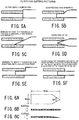
- the volume of the blood separation member for 100 ⁇ L of blood is 16 mm (length) ⁇ 8 mm (width) ⁇ 0.37 mm (height) (see Fig. 4B ), it is about 47.36 mm 3 in volume when converted.
- the object of the experiment is to consider "cutting angle of the end in the thickness direction" (hereinafter, also referred to as “end thickness cutting angle”) required for a quick separation of 100 ⁇ L of blood and collection of plasma, by decreasing the "thickness" of the end of the blood separation member, in other word, by decreasing the "thickness” of the end of the blood separation member through the end cutting at various acute angles (angles tapering the end in a shape of a triangle), Note that the above-mentioned cutting in the thickness direction at an angle tapering in the shape of a triangle is hereinafter also referred to as "(end thickness cutting in a triangle” or simply “(end thickness cutting).”
- the thickness of the blood separation member used in experiment 2 is greater than the height of the gap (space) between the two collecting members of the plasma collection part (here, 0.15 mm, hereinafter also referred to as a "gap of the collection part"), in order to improve a contact between the gap of the collection part and the end of the blood separation member, the end of the blood separation member is cut at different acute angles, in other word, the end is subject to the end thickness cutting, so that the "thickness" of the end of the blood separation member is decreased.
- angles totaled in seven: 5°, 6.7°, 7°, 10°, 20°, 60°, 80°, and 90° (without cutting).
- the plasma collection rates were: 12% at 5°, 30% at 6.7°, 30% at 7°, 12% at 10°, 6% at 20°, 0% at 60°, 80°, and 90° of end thickness cutting angles (see Table 1).
- the plasma collection rates were particularly excellent when the end thickness cutting angles of the blood separation member were 6.7°-7°.
- the end thickness cutting angle was preferably not less than 5° and not more than 20°, more preferably not less than 5° and not more than 10°, even more preferably not less than 6.7° and not more than 7°.
- an optimal plasma collection rate can be obtained by the blood separation member having the dimensions of the blood separation member of 16 mm (length) ⁇ 8 mm (width) ⁇ 0.37 mm (height (thickness)), and by applying the work to the end at "the end cutting angle" of not less than 6.7° and not more than 7°, so that the thickness of the end is gradually decreased toward the tip end
- the blood separation member having dimensions of 16 mm (length) ⁇ 8 mm (width) ⁇ 0.37 mm (thickness) and with the end cut at the thickness cutting angle of 7° (hereinafter, may be abbreviated as "the thickness of 0.37 mm, the end thickness cutting angle of 7°") was used, unless otherwise mentioned (see Fig. 4C ).
- the object is to consider means for preventing the slipping of blood on the surface of the blood separation member.
- the blood reserving member (made of hydrophobically treated glass, this time) having a shape as shown in Fig. 4D for example, is placed on the upper surface of a blood separation member, the blood is dropped on an upstream side of the blood reserving member (opposite side to the plasma collection part), and results of the plasma collection is compared.
- the blood reserving part 62 which is a rectangular protrusion at a lower part of the blood inlet 61 of the blood inlet part 6 in order to prevent the above-mentioned leaking phenomenon over the surface of the blood separation member.
- the blood reserving part may be any other shape such as a cylindrical shape, when it is effective as a temporal blood reservoir forming part (guiding part for forming temporal blood reservoir) as mentioned above.
- the collection rates are compared by dropping 100 ⁇ L of blood on the blood separation members each having a thickness of 0.25 mm, 0.37 mm, or 0.78 mm and length ⁇ width ⁇ thickness (in short, the volume) of approximately 47 mm 3 .
- the thickness of 0.37 mm was preferable when the amount of blood was 100 ⁇ L.
- the volume of the blood separation member is related to the collection rate, to collect plasma from 100 ⁇ L of blood, it is proven that, considering in terms of volume, the volume of 32 mm 3 (where the thickness is 0.25 mm; 16 mm (length) ⁇ 8 mm (width) ⁇ 0.25 mm (thickness)) or less is small, the volume of 99.84 mm 3 (when the thickness was 0.78 mm; 16 mm (length) ⁇ 8 mm (width) ⁇ 0.78 mm (thickness)) or more was too large; but the volume of 47.36 mm 3 (when the thickness was 0.37 mm; 16 mm (length) ⁇ 8 mm (width) ⁇ 0.37 mm (thickness)) is the most effective, a large effect being 30%of the collection rate can be obtained.
- the volume of the blood separation member was not the volume after applying the end thickness cutting at angle 7°, but the volume before applying the end thickness cutting at angle 7°. The same is true for the following experiments too. (Incidentally, the volume after cutting at 7° is 42.9 mm 3 .) [Table 3] Thickness of blood separation member 0.25 mm 0.37 mm 0.78 mm Plasma collection rate 0 30% 0
- the blood dropping amount in the blood separation member to which the end thickness cutting at 7°was applied, when its volume was set to be 47.36 mm 3 , it is important and preferable to set the blood dropping amount to 75 ⁇ L - 100 ⁇ L, and more preferably to set to 100 ⁇ L. In other words, when the blood dropping amount is 100 ⁇ L, it is important that the volume of the blood separation member is preferably set to near at 47.36 mm 3 .
- the volume of the blood separation member is preferably 74 mm 3 - 99.84 mm 3 , and more preferably, 74 mm 3 .
- the regular blood separation member one having the thickness of 0.37 mm and with the end thickness cutting angle of 7° is used, and conditions of members other than the collecting member are the same.
- the collecting member was made of material other than glass, its result was that the plasma collection rates were 10% for PS (polystyrene), 6.3% for PET (polyethylene terephthalate), 4.5% for PC (polycarbonate), 0.9% for PP (polypropylene), and 0% for PVC (polyvinyl chloride) (see Table 6).
- Object To consider an influence of presence/absence of an opening (vent) in the plasma collection part due to differences in end thickness cutting angles of the blood separation member on the plasma collection rate.
- the plasma collection rates from 100 ⁇ L of blood is examined by combining presence/absence of an opening (vent) in the plasma collection part and blood separation members having various end thickness cutting angles (angles tapering toward the tip end in a shape of a triangle).
- an absence of a vent means a mode in which the opening 45 is sealed with some means such as a film or the like.
- the opening 45 can be sealed by a same adhesive as an adhesive 43 for the plasma collection members or sealed by the same material as the collecting members. However, it is needed to secure an air passage. In the experiment, the opening 45 is sealed with the adhesive, but the width of the plasma collecting area 44 is made greater than that of the blood separation member and partially made hydrophobic in order that an air passage is secured.
- a plasma collection rate of the blood for 100 ⁇ L of blood using separation member having a dimensions of 16 mm (length) ⁇ 8 mm (width) is examined, wherein the end of the separation member is cut so that it is narrowed toward the tip end (in a shape of triangle) (when seen from above, the end of the blood separation member is formed in a shape of a triangle with a tip end angle of 60°; see Fig. 6A )
- the plasma separation apparatus of the embodiment of the invention is effective as a sampling apparatus for the biochemical examination of blood.
- Examination items HDL LDL T-CHO TG ALP T-BIL CRE UA Units mg/dL mg/dL mg/dL mg/dL U/L mg/dL mg/dL mg/dL Stand ards Lower limit 30 60 128 42 130 0.2 0.47 2.9 Upper limit 85 119 250 168 350 1.2 1.09 7.7 Blood A Centrifuge separation 50 101 171 256 309 1.28 0.74 4.88 Embodiment 1 49 98 168 275 313 1.29 0.80 4.91 % to centrifuge 98.3% 97.4% 98.6% 107.7% 101.2% 101.0% 108.9% 100.5% Blood B Centrifuge separation 53 86 146 99 132 0.44 0.69 4.43 Embodiment 1 53 86 145 103 141 0.44 0.72 4.50 % to centrifuge 99.4% 99.5% 99.4% 104
- Method the plasma collection rate by using a blood separation member made of polycarbonate (to which hydrophilic resin sputtering or plasma hydrophilizing treatment were applied) and subjected to the end thickness cutting at 7°, are examined, and further the plasma collection rate are examined when the end of the blood separation member was perpendicularly notched. Note that ten notches were provided.
- the blood separation member provided with ten notches was subjected to two experiments. Surprisingly, the collection rates were increased and their rates of increase were 1.3-times or 1.5-times, respectively. Especially in the experiment 13-1, the collection rate is 28.7% which was excellent.
- One of other embodiment of the invention is an improved type of the embodiment 1 and is a plasma separation apparatus 10 comprises at least a core part 20 and a housing part 50 ( Fig. 7 to Fig.10 ).
- Fig. 7 shows an external view of the plasma separation apparatus 10 of the invention
- Fig. 8 shows a sectional view
- Fig. 9 shows an explosive view
- Fig. 10 shows a perspective view of the outer of a core part 30 after it is assembled (a support member 801 for separation not shown).
- the housing part 50 containing the core part 20 is provided with at least a blood inlet part 60 and a collecting body part 70.
- the blood inlet part 60 is provided at an upper part of a blood separation part 30 contained in the housing, and is provided with a blood inlet 601, a blood reserving part 602, and optionally, a blood deployment observation window 603 and other parts as needed.
- the blood reserving part 602 has the effect of temporarily forming a blood reservoir, as mentioned above. With this, after blood is dropped, a part of it is prevented from slipping over the upper surface of the blood separation member, leaking therefrom (in this state, the blood cannot be separated by the blood separation member) and flowing into the plasma collection part (the blood is mixed into the plasma) . (Note that, the blood reserving part also has a function to exhibit the blood separating effectiveness of the blood separation member more effectively.)
- a part of the dropped blood usually flows while forming the passage by the capillary phenomenon in the blood separation member, but the remaining blood would flood over the surface of the separation member which phenomenon can be caused not a few, and as a result, a part of the blood would flow into the collection part without separating. Therefore, to address this problem, such blood reserving part is disposed, so that the somewhat flooding blood on the member surface is temporarily reserved as is by the surface tension, and thereafter gradually flows into the separation member, so that a leaking phenomenon as mentioned above can be prevented.
- the blood reserving part 602 is placed to be in contact with the upper surface of the blood separation member 301, a close contact with the blood separation member 301 is not necessary. Some gaps are allowed to be unless the blood reserving part loses its effectiveness as the blood reserving part (temporal blood reservoir) by surface tension and, unless the blood slips over the upper surface of the blood separation member, leaks therefrom, and flows into the collection part through the gaps.
- Such the blood reserving part can be of any shape, can be made of any material, and can be placed anywhere, when its effect as the above-mentioned “temporal blood reservoir forming part” (or “guiding part for forming temporal blood reservoir”) is maintained.
- the blood reserving part 602 is formed in a convex part extending along the shape of the blood inlet 601 and perpendicularly extending downward therefrom, but it may be, for example, circular, comb-shape, U-shape, or channel-shape, and may be bar-shaped like 33 shown in Fig. 4D . Furthermore, like the previous embodiment, it may be provided on the lower surface of the blood inlet 601 by being integral molded with the housing 50, or, for example, the bar-shaped like a member mentioned above may be integrally molded with a pedestal for a separating part 302 in a bridge shape. Note that the blood reserving part also has a function to exhibit the effectiveness of blood separation of the blood separation member to the maximum.
- a collecting body part 70 it is provided with a plasma deployment observation window 701, an opening 702 or the like, as needed.
- the opening 702 may include a film that allows air to pass there-through but not liquid, a valve, a connector to an examination system or the like, or a liquid (plasma) reserving member.
- the opening 702 is not necessarily required.
- the structure of a core part 20 of the plasma separation apparatus 10 of the invention generally includes a blood separation part 30 and a plasma collection part 40 ( Fig. 9 ).
- the blood separation part 30 includes at least, a blood separation member 301, a pedestal 302 for blood separation part, and a receptor 303.
- the blood separation member 301 is mounted on the pedestal 302 for blood separation part ( Fig. 9 ) and an end thereof is inserted into a gap between two plasma collection members ( Fig. 3 , Fig. 8 ).
- the plasma collection part 40 is provided with at least two sheets of the plasma collection members 401, 402, both ends of those plasma collection members 401, 402 are sealed by such means as an adhesive or the like, so that a plasma collecting area 404 surrounded by the plasma collection members 401, 402 and the adhesive part is formed ( Fig. 8 to Fig. 10 ).
- an adhesive tape As adhesive member, an adhesive tape, an adhesive, and the like may be considered. Integral molding without using the adhesive may be carried out, when the adhesive member is made of the same material as that of the correcting member.
- the plasma collection part 40 may be provided with an accessory part 90 at a distal end.
- One mode of the accessory part 90 may be provided with a connecting part (connector) for connecting to the examination system, an outer container or the like, the liquid (plasma) reservoir, valve or the like.
- the receptors 303 and 403 respectively receive members of a supporting part 80 for separation to interconnect the pedestal 302 for blood separation and the plasma collection member 402, and integrate core part 20 (the blood separation part 30 and the plasma collection part 40).
- the supporting part 80 for separation is removed to disassemble the core part 20, so that the plasma collection part 40 can be separated.
- the structure of the supporting part 80 for separation can be any form when the plasma collection part and the blood separation part can be safely separated.
- the core part may be configured that the plasma collection part and the blood separation part can be cut off.
- Materials for the blood separation member 301 are not limited to those in the above-mentioned embodiment 1, for example, fiber composed of glass or synthetic polymers having a small fiber diameter, laminated porous polymeric sheet or thin nonwoven fabric and the like can be used when they have a function and effectiveness as a blood separation member.
- the same materials as in embodiment 1 may be used, but from viewpoints of cost and manufacture, it is preferable to design to make it by using a material such as resin and the like which may be easily molded.
- a method for separating plasma from blood using a plasma separation apparatus of the invention comprises at least the following steps:
- this method does not require any special apparatus such as a centrifuge separator, a suctioning or pressurizing apparatus (tool), or the like and can be performed by an ordinary parson without training who is not a medical worker, it can deal with needs of a person at home, a resident in a remote place or in developing countries, or a minority or a majority of people, plasma separation can be performed easily and quickly and separated plasma can be send to the examination facilities as it is. Thus, the apparatus is very useful.
- a plasma separation apparatus of the invention has been particularly described with reference to the separation of plasma, it can be also used for an examination of blood cells trapped in a blood separation member, in particular, an examination of HbA1c and the like using red blood cells, an examination of presence/absence of HIV-B using white blood cells and an examination regarding to immune cells and the like.
- a plasma separation apparatus of the invention may be formed as a blood examination kit, together with a minutia amount blood collecting device (blood sampling device).
- One embodiment of the invention is a separation apparatus for blood. It is a plasma separation apparatus when the blood sampling device includes an anticoagulant, or it is a serum separation apparatus when the blood sampling device does not include an anticoagulant.
- a plasma separation apparatus of the invention does not require a special apparatus such as a centrifuge separator, a suctioning or pressurizing apparatus (tool), or the like, and is easy to handle even the minute amount of blood and available for an examination for medical care at home or in any remoted area or in developing countries at a low cost.
- a plasma separation apparatus comprising, a blood separation part having a blood separation member, and a plasma collection part having a plasma collection member, wherein the blood separation member is mounted on a hydrophobic pedestal and includes a blood receiving area and a plasma separation area that is connected to the plasma collection part, and the plasma separation part has the cross-sectional area thereof gradually decreasing toward the plasma collection part.
- the plasma separation apparatus according to claim A or B, wherein the blood separation part comprises a blood reserving part on the upper surface side of the blood separation member for temporarily reserving blood.
- a blood examination kit comprising the plasma separation apparatus according to any one of claims A to E and a blood collection tool.
- a plasma separation method for separating plasma using a plasma separation apparatus comprising a blood separation part having a blood separation member and a plasma collection part having a plasma collection member, wherein the blood separation member arranged on a hydrophobic pedestal has a blood receiving area and a plasma separation area connected to the plasma collection part, a cross-sectional area of the plasma separation area is gradually decreased toward the plasma collection part; the plasma separation method comprising steps of ; separating the plasma from the blood received in the blood receiving area, in the plasma separation area, and collecting the separated plasma in the plasma collection part.
- the blood separation part comprises a blood reserving part on the upper-surface side of the blood separation member so that blood is received in the blood receiving area after temporarily being reserved in the blood reserving part.
- a plasma separation apparatus comprising a blood separation part and a plasma collection part, wherein the blood separation part has a blood separation member, a blood reserving part for temporarily reserving blood on the upper surface of the blood separation member, and a hydrophobic pedestal for supporting the blood separation member, the plasma collection part is formed with a plasma collecting area which is a gap between collecting members; and an end of the blood separation member on the plasma collection part side is inserted into the gap in the plasma collection part, a cross-sectional area of the end being gradually decreased toward the plasma collection part.
- the plasma separation apparatus according to claim a or b, further comprising a support member for separation, for separating the blood separation part and the plasma collection part.
- a plasma separation method comprising steps of: providing a plasma separation apparatus in which an end of a blood separation member on a plasma collection part side is inserted into a gap in the plasma collection part; introducing blood to the blood separation member through a blood reserving part serving as a temporal blood reservoir from a blood inlet of a blood inlet part; separating the blood introduced into the blood separation part into cellular and plasma components, as the blood is developed while forming a passage in the blood separation part owing to an wicking effect of the blood separation member; and collecting the separated plasma component in the plasma collection part as a liquid component, the separated plasma component forming the passage in the gap in the plasma collection part through the communication/corporation between the wicking effect of the blood separation member and a capillary phenomenon of the plasma collection part.
- the plasma separation method according to claim d comprising; a step of separating the plasma separation apparatus into the blood separation part and the plasma collection part after the completion of plasma collection.
- the invention is useful in separating blood components to prepare a sample for blood examination easily, conveniently, and safely at a low cost even in the absence of a medical worker.
Landscapes
- Health & Medical Sciences (AREA)
- Life Sciences & Earth Sciences (AREA)
- Chemical & Material Sciences (AREA)
- Engineering & Computer Science (AREA)
- Biomedical Technology (AREA)
- Physics & Mathematics (AREA)
- Hematology (AREA)
- General Health & Medical Sciences (AREA)
- Pathology (AREA)
- Analytical Chemistry (AREA)
- Immunology (AREA)
- General Physics & Mathematics (AREA)
- Biochemistry (AREA)
- Molecular Biology (AREA)
- Food Science & Technology (AREA)
- Medicinal Chemistry (AREA)
- Urology & Nephrology (AREA)
- Biophysics (AREA)
- Ecology (AREA)
- Hydrology & Water Resources (AREA)
- Veterinary Medicine (AREA)
- Animal Behavior & Ethology (AREA)
- Public Health (AREA)
- Surgery (AREA)
- Medical Informatics (AREA)
- Dispersion Chemistry (AREA)
- Clinical Laboratory Science (AREA)
- Chemical Kinetics & Catalysis (AREA)
- Heart & Thoracic Surgery (AREA)
- Investigating Or Analysing Biological Materials (AREA)
- External Artificial Organs (AREA)
- Sampling And Sample Adjustment (AREA)
Applications Claiming Priority (2)
| Application Number | Priority Date | Filing Date | Title |
|---|---|---|---|
| JP2016196059A JP6366025B2 (ja) | 2016-10-03 | 2016-10-03 | 血漿分離装置及び血漿分離方法 |
| PCT/JP2017/019507 WO2018066167A1 (fr) | 2016-10-03 | 2017-05-25 | Dispositif de séparation de plasma et procédé de séparation de plasma |
Publications (2)
| Publication Number | Publication Date |
|---|---|
| EP3524977A1 true EP3524977A1 (fr) | 2019-08-14 |
| EP3524977A4 EP3524977A4 (fr) | 2020-06-24 |
Family
ID=61831426
Family Applications (1)
| Application Number | Title | Priority Date | Filing Date |
|---|---|---|---|
| EP17858007.2A Withdrawn EP3524977A4 (fr) | 2016-10-03 | 2017-05-25 | Dispositif de séparation de plasma et procédé de séparation de plasma |
Country Status (10)
| Country | Link |
|---|---|
| US (1) | US20190242870A1 (fr) |
| EP (1) | EP3524977A4 (fr) |
| JP (1) | JP6366025B2 (fr) |
| CN (1) | CN109804243B (fr) |
| AU (1) | AU2017340091A1 (fr) |
| BR (1) | BR112019006752A2 (fr) |
| CA (1) | CA3040001A1 (fr) |
| RU (1) | RU2019112804A (fr) |
| SG (1) | SG11201902975TA (fr) |
| WO (1) | WO2018066167A1 (fr) |
Families Citing this family (9)
| Publication number | Priority date | Publication date | Assignee | Title |
|---|---|---|---|---|
| WO2017210199A1 (fr) | 2016-05-31 | 2017-12-07 | Oregon State University | Dispositifs fluidiques pour séparation chromatographique et leurs procédés de fabrication et d'utilisation |
| US11311874B2 (en) | 2017-06-07 | 2022-04-26 | Oregon Slate University | Polymer-based well plate devices and fluidic systems and methods of making and using the same |
| US11207455B2 (en) * | 2018-05-14 | 2021-12-28 | Oregon State University | Membrane device for blood separation and methods of making and using the same |
| CN112512689B (zh) * | 2018-06-12 | 2023-09-01 | 那乌达耶歌诺斯蒂克有限责任公司 | 采集血浆的装置和方法 |
| US12053779B2 (en) | 2019-10-30 | 2024-08-06 | Zoetis Services Llc | System and method for separation of blood components |
| WO2021117757A1 (fr) * | 2019-12-10 | 2021-06-17 | 株式会社堀場製作所 | Outil de collecte d'échantillon, procédé de fabrication d'outil de collecte d'échantillon et système de mesure |
| JP7624827B2 (ja) * | 2019-12-10 | 2025-01-31 | 株式会社堀場製作所 | 検体採取具、検体採取具の製造方法、及び測定システム |
| JPWO2022114031A1 (fr) * | 2020-11-25 | 2022-06-02 | ||
| EP4659670A1 (fr) * | 2024-05-24 | 2025-12-10 | Satio, Inc. | Timbre dermique pour collecter un échantillon physiologique |
Family Cites Families (22)
| Publication number | Priority date | Publication date | Assignee | Title |
|---|---|---|---|---|
| NL8800796A (nl) * | 1988-03-29 | 1989-10-16 | X Flow Bv | Werkwijze voor de chemische analyse van bestanddelen van een lichaamsvloeistof, alsmede een testinrichting en testpakket voor een dergelijke analyse. |
| CA1325175C (fr) * | 1989-05-25 | 1993-12-14 | Asahi Medical Co., Ltd. | Separateur compact de plasma; l'appareil correspondant |
| DK0832430T3 (da) * | 1995-05-09 | 2006-11-20 | Beckman Coulter Inc | Anordninger og metoder til at separere cellulære blodkomponenter fra den flydende del af blodet |
| DE60043049D1 (de) * | 1999-12-28 | 2009-11-12 | Arkray Inc | Bluttestvorrichtung |
| US7531362B2 (en) * | 2001-06-07 | 2009-05-12 | Medmira Inc. | Rapid diagnostic assay |
| JP2003075434A (ja) * | 2001-08-31 | 2003-03-12 | Asahi Kasei Corp | 血漿分離方法及び血漿分離装置 |
| US6830685B2 (en) * | 2001-12-05 | 2004-12-14 | Fresenius Usa, Inc. | Filtering device with associated sealing design and method |
| CN100492006C (zh) * | 2002-11-19 | 2009-05-27 | 积水医疗株式会社 | 过滤仪及血液检测容器 |
| JP4387166B2 (ja) * | 2002-11-19 | 2009-12-16 | 積水メディカル株式会社 | 血漿もしくは血清分離膜を用いたフィルタ装置及び血漿もしくは血清分離方法 |
| JP2004294388A (ja) * | 2003-03-10 | 2004-10-21 | Arkray Inc | 成分分析装置 |
| CN1456892A (zh) * | 2003-06-06 | 2003-11-19 | 浙江大学 | 全血尿酸浓度检测试纸条 |
| CN102698332B (zh) * | 2006-10-30 | 2015-08-05 | 甘布罗伦迪亚股份公司 | 用于体外流体处理套件的空气分离器 |
| CN100503019C (zh) * | 2007-01-12 | 2009-06-24 | 中国科学院上海有机化学研究所 | 一种血浆脂质成份吸附分离聚合物多孔膜材料、制备及其应用 |
| KR101032691B1 (ko) * | 2009-04-17 | 2011-05-06 | (주)디지탈옵틱 | 신속한 혈구분리가 가능한 질병진단용 바이오센서 |
| KR101046156B1 (ko) * | 2010-03-12 | 2011-07-04 | 주식회사 나노엔텍 | 혈구 분리 칩 |
| DE102011078961B4 (de) * | 2011-07-11 | 2021-02-18 | Robert Bosch Gmbh | System zum Separieren von Körperflüssigkeitsbestandteilen und Verfahren zum Herstellen eines derartigen Systems |
| CN102757610B (zh) * | 2012-07-24 | 2013-10-30 | 武汉德晟化工科技有限公司 | 一种抗辐照血清分离胶 |
| CN102773122A (zh) * | 2012-08-06 | 2012-11-14 | 苏州汶颢芯片科技有限公司 | 一种离心式微流控血清分离芯片及其制备方法 |
| EP2972184A4 (fr) * | 2013-03-15 | 2016-11-30 | Theranos Inc | Procédés et dispositifs pour collecte d'échantillons et séparation d'échantillons |
| CN103816816B (zh) * | 2014-02-28 | 2016-02-03 | 中国科学院长春应用化学研究所 | 一种聚合物膜材料及其制备方法 |
| CN105879936B (zh) * | 2016-03-31 | 2017-10-13 | 张鹏 | 全血过滤及定量移取微流控芯片 |
| CN205517817U (zh) * | 2016-03-31 | 2016-08-31 | 苏州市博纳泰科生物技术有限公司 | 防倒流微阀 |
-
2016
- 2016-10-03 JP JP2016196059A patent/JP6366025B2/ja active Active
-
2017
- 2017-05-25 SG SG11201902975TA patent/SG11201902975TA/en unknown
- 2017-05-25 BR BR112019006752A patent/BR112019006752A2/pt not_active IP Right Cessation
- 2017-05-25 US US16/339,031 patent/US20190242870A1/en not_active Abandoned
- 2017-05-25 CN CN201780061587.9A patent/CN109804243B/zh active Active
- 2017-05-25 RU RU2019112804A patent/RU2019112804A/ru not_active Application Discontinuation
- 2017-05-25 CA CA3040001A patent/CA3040001A1/fr not_active Abandoned
- 2017-05-25 EP EP17858007.2A patent/EP3524977A4/fr not_active Withdrawn
- 2017-05-25 WO PCT/JP2017/019507 patent/WO2018066167A1/fr not_active Ceased
- 2017-05-25 AU AU2017340091A patent/AU2017340091A1/en not_active Abandoned
Also Published As
| Publication number | Publication date |
|---|---|
| RU2019112804A (ru) | 2020-11-06 |
| US20190242870A1 (en) | 2019-08-08 |
| CA3040001A1 (fr) | 2018-04-12 |
| JP2018059756A (ja) | 2018-04-12 |
| RU2019112804A3 (fr) | 2020-11-06 |
| AU2017340091A1 (en) | 2019-05-02 |
| EP3524977A4 (fr) | 2020-06-24 |
| BR112019006752A2 (pt) | 2019-09-03 |
| JP6366025B2 (ja) | 2018-08-01 |
| CN109804243A (zh) | 2019-05-24 |
| SG11201902975TA (en) | 2019-05-30 |
| WO2018066167A1 (fr) | 2018-04-12 |
| CN109804243B (zh) | 2020-11-10 |
Similar Documents
| Publication | Publication Date | Title |
|---|---|---|
| EP3524977A1 (fr) | Dispositif de séparation de plasma et procédé de séparation de plasma | |
| JP7502486B2 (ja) | 生物体液の極微標本管理装置 | |
| EP2264453B1 (fr) | Procédé de filtrage de sang | |
| Sethu et al. | Microfluidic diffusive filter for apheresis (leukapheresis) | |
| US8889071B2 (en) | Apparatus and method for separating plasma | |
| JP6193474B2 (ja) | 生体液採取移送装置ならびに生体液分離および検査システム | |
| US20200359952A1 (en) | Device for Cross Flow Filtration | |
| AU2012203289B2 (en) | Plasma separation | |
| JP2000083649A (ja) | 細胞分離・回収装置および細胞の分離・回収方法 | |
| CN104111324B (zh) | 采血传输设备、血液分离和测试系统和采血传输系统 | |
| US20050214927A1 (en) | Sample preparation device and method | |
| JP2007518978A (ja) | 血漿用オンデマンドチューブ | |
| JP6240308B2 (ja) | 生体液分離装置並びに生体液の分離および検査システム | |
| JP2017522142A (ja) | 圧力補助血漿分離 | |
| WO2014159197A1 (fr) | Séparation de plasma du sang en utilisant un dispositif de filtration et ses procédés | |
| JP6707031B2 (ja) | 細胞分離材および細胞分離方法 | |
| WO2019025914A1 (fr) | Dispositif de séparation de plasma | |
| WO2009042522A2 (fr) | Lyse microfluidique | |
| JP4078460B2 (ja) | 血漿分離フィルター、それを用いる血漿分離方法および血漿分離装置 | |
| JP6588602B2 (ja) | 血漿分離装置及び血漿分離方法 | |
| JP6877745B2 (ja) | 血漿分離装置及び血漿分離方法 | |
| JP2003075434A (ja) | 血漿分離方法及び血漿分離装置 | |
| Guevara-Pantoja et al. | A Microfluidic Device for Passive Separation of Platelet-Rich Plasma from Whole Blood | |
| JP2002508698A (ja) | 流体サンプルを濾過するためのフィルタを組み込んだ装置 |
Legal Events
| Date | Code | Title | Description |
|---|---|---|---|
| STAA | Information on the status of an ep patent application or granted ep patent |
Free format text: STATUS: THE INTERNATIONAL PUBLICATION HAS BEEN MADE |
|
| PUAI | Public reference made under article 153(3) epc to a published international application that has entered the european phase |
Free format text: ORIGINAL CODE: 0009012 |
|
| STAA | Information on the status of an ep patent application or granted ep patent |
Free format text: STATUS: REQUEST FOR EXAMINATION WAS MADE |
|
| 17P | Request for examination filed |
Effective date: 20190430 |
|
| AK | Designated contracting states |
Kind code of ref document: A1 Designated state(s): AL AT BE BG CH CY CZ DE DK EE ES FI FR GB GR HR HU IE IS IT LI LT LU LV MC MK MT NL NO PL PT RO RS SE SI SK SM TR |
|
| AX | Request for extension of the european patent |
Extension state: BA ME |
|
| DAV | Request for validation of the european patent (deleted) | ||
| DAX | Request for extension of the european patent (deleted) | ||
| A4 | Supplementary search report drawn up and despatched |
Effective date: 20200525 |
|
| RIC1 | Information provided on ipc code assigned before grant |
Ipc: G01N 1/10 20060101ALI20200516BHEP Ipc: G01N 33/48 20060101AFI20200516BHEP |
|
| STAA | Information on the status of an ep patent application or granted ep patent |
Free format text: STATUS: THE APPLICATION IS DEEMED TO BE WITHDRAWN |
|
| 18D | Application deemed to be withdrawn |
Effective date: 20211201 |