EP3525014B1 - Laminierter lichtabschirmender film und lichtabschirmender ring für optische vorrichtung damit, linseneinheit und kameramodul - Google Patents
Laminierter lichtabschirmender film und lichtabschirmender ring für optische vorrichtung damit, linseneinheit und kameramodul Download PDFInfo
- Publication number
- EP3525014B1 EP3525014B1 EP17858240.9A EP17858240A EP3525014B1 EP 3525014 B1 EP3525014 B1 EP 3525014B1 EP 17858240 A EP17858240 A EP 17858240A EP 3525014 B1 EP3525014 B1 EP 3525014B1
- Authority
- EP
- European Patent Office
- Prior art keywords
- light
- blocking
- blocking layer
- black
- film
- Prior art date
- Legal status (The legal status is an assumption and is not a legal conclusion. Google has not performed a legal analysis and makes no representation as to the accuracy of the status listed.)
- Active
Links
Images

Classifications
-
- G—PHYSICS
- G02—OPTICS
- G02B—OPTICAL ELEMENTS, SYSTEMS OR APPARATUS
- G02B5/00—Optical elements other than lenses
- G02B5/003—Light absorbing elements
-
- G—PHYSICS
- G02—OPTICS
- G02B—OPTICAL ELEMENTS, SYSTEMS OR APPARATUS
- G02B5/00—Optical elements other than lenses
- G02B5/005—Diaphragms
-
- C—CHEMISTRY; METALLURGY
- C08—ORGANIC MACROMOLECULAR COMPOUNDS; THEIR PREPARATION OR CHEMICAL WORKING-UP; COMPOSITIONS BASED THEREON
- C08J—WORKING-UP; GENERAL PROCESSES OF COMPOUNDING; AFTER-TREATMENT NOT COVERED BY SUBCLASSES C08B, C08C, C08F, C08G or C08H
- C08J7/00—Chemical treatment or coating of shaped articles made of macromolecular substances
- C08J7/04—Coating
- C08J7/0427—Coating with only one layer of a composition containing a polymer binder
-
- G—PHYSICS
- G02—OPTICS
- G02B—OPTICAL ELEMENTS, SYSTEMS OR APPARATUS
- G02B13/00—Optical objectives specially designed for the purposes specified below
- G02B13/001—Miniaturised objectives for electronic devices, e.g. portable telephones, webcams, PDAs, small digital cameras
-
- G—PHYSICS
- G02—OPTICS
- G02B—OPTICAL ELEMENTS, SYSTEMS OR APPARATUS
- G02B27/00—Optical systems or apparatus not provided for by any of the groups G02B1/00 - G02B26/00, G02B30/00
- G02B27/0018—Optical systems or apparatus not provided for by any of the groups G02B1/00 - G02B26/00, G02B30/00 with means for preventing ghost images
-
- G—PHYSICS
- G02—OPTICS
- G02B—OPTICAL ELEMENTS, SYSTEMS OR APPARATUS
- G02B5/00—Optical elements other than lenses
-
- G—PHYSICS
- G02—OPTICS
- G02B—OPTICAL ELEMENTS, SYSTEMS OR APPARATUS
- G02B7/00—Mountings, adjusting means, or light-tight connections, for optical elements
- G02B7/02—Mountings, adjusting means, or light-tight connections, for optical elements for lenses
-
- G—PHYSICS
- G02—OPTICS
- G02B—OPTICAL ELEMENTS, SYSTEMS OR APPARATUS
- G02B7/00—Mountings, adjusting means, or light-tight connections, for optical elements
- G02B7/02—Mountings, adjusting means, or light-tight connections, for optical elements for lenses
- G02B7/021—Mountings, adjusting means, or light-tight connections, for optical elements for lenses for more than one lens
-
- G—PHYSICS
- G03—PHOTOGRAPHY; CINEMATOGRAPHY; ANALOGOUS TECHNIQUES USING WAVES OTHER THAN OPTICAL WAVES; ELECTROGRAPHY; HOLOGRAPHY
- G03B—APPARATUS OR ARRANGEMENTS FOR TAKING PHOTOGRAPHS OR FOR PROJECTING OR VIEWING THEM; APPARATUS OR ARRANGEMENTS EMPLOYING ANALOGOUS TECHNIQUES USING WAVES OTHER THAN OPTICAL WAVES; ACCESSORIES THEREFOR
- G03B11/00—Filters or other obturators specially adapted for photographic purposes
-
- G—PHYSICS
- G03—PHOTOGRAPHY; CINEMATOGRAPHY; ANALOGOUS TECHNIQUES USING WAVES OTHER THAN OPTICAL WAVES; ELECTROGRAPHY; HOLOGRAPHY
- G03B—APPARATUS OR ARRANGEMENTS FOR TAKING PHOTOGRAPHS OR FOR PROJECTING OR VIEWING THEM; APPARATUS OR ARRANGEMENTS EMPLOYING ANALOGOUS TECHNIQUES USING WAVES OTHER THAN OPTICAL WAVES; ACCESSORIES THEREFOR
- G03B17/00—Details of cameras or camera bodies; Accessories therefor
- G03B17/02—Bodies
-
- G—PHYSICS
- G03—PHOTOGRAPHY; CINEMATOGRAPHY; ANALOGOUS TECHNIQUES USING WAVES OTHER THAN OPTICAL WAVES; ELECTROGRAPHY; HOLOGRAPHY
- G03B—APPARATUS OR ARRANGEMENTS FOR TAKING PHOTOGRAPHS OR FOR PROJECTING OR VIEWING THEM; APPARATUS OR ARRANGEMENTS EMPLOYING ANALOGOUS TECHNIQUES USING WAVES OTHER THAN OPTICAL WAVES; ACCESSORIES THEREFOR
- G03B30/00—Camera modules comprising integrated lens units and imaging units, specially adapted for being embedded in other devices, e.g. mobile phones or vehicles
-
- C—CHEMISTRY; METALLURGY
- C08—ORGANIC MACROMOLECULAR COMPOUNDS; THEIR PREPARATION OR CHEMICAL WORKING-UP; COMPOSITIONS BASED THEREON
- C08J—WORKING-UP; GENERAL PROCESSES OF COMPOUNDING; AFTER-TREATMENT NOT COVERED BY SUBCLASSES C08B, C08C, C08F, C08G or C08H
- C08J2300/00—Characterised by the use of unspecified polymers
-
- C—CHEMISTRY; METALLURGY
- C08—ORGANIC MACROMOLECULAR COMPOUNDS; THEIR PREPARATION OR CHEMICAL WORKING-UP; COMPOSITIONS BASED THEREON
- C08J—WORKING-UP; GENERAL PROCESSES OF COMPOUNDING; AFTER-TREATMENT NOT COVERED BY SUBCLASSES C08B, C08C, C08F, C08G or C08H
- C08J2400/00—Characterised by the use of unspecified polymers
-
- G—PHYSICS
- G03—PHOTOGRAPHY; CINEMATOGRAPHY; ANALOGOUS TECHNIQUES USING WAVES OTHER THAN OPTICAL WAVES; ELECTROGRAPHY; HOLOGRAPHY
- G03B—APPARATUS OR ARRANGEMENTS FOR TAKING PHOTOGRAPHS OR FOR PROJECTING OR VIEWING THEM; APPARATUS OR ARRANGEMENTS EMPLOYING ANALOGOUS TECHNIQUES USING WAVES OTHER THAN OPTICAL WAVES; ACCESSORIES THEREFOR
- G03B11/00—Filters or other obturators specially adapted for photographic purposes
- G03B11/04—Hoods or caps for eliminating unwanted light from lenses, viewfinders or focusing aids
- G03B11/045—Lens hoods or shields
-
- G—PHYSICS
- G03—PHOTOGRAPHY; CINEMATOGRAPHY; ANALOGOUS TECHNIQUES USING WAVES OTHER THAN OPTICAL WAVES; ELECTROGRAPHY; HOLOGRAPHY
- G03B—APPARATUS OR ARRANGEMENTS FOR TAKING PHOTOGRAPHS OR FOR PROJECTING OR VIEWING THEM; APPARATUS OR ARRANGEMENTS EMPLOYING ANALOGOUS TECHNIQUES USING WAVES OTHER THAN OPTICAL WAVES; ACCESSORIES THEREFOR
- G03B9/00—Exposure-making shutters; Diaphragms
- G03B9/02—Diaphragms
Definitions
- the present invention relates to a multilayer light-blocking film, and a light-blocking ring for optical equipment, a lens unit, and a camera module using the same.
- a camera module for taking an image of an object and converting it into an image signal is built into electronic equipment, for example, an information communication terminal such as a cellular phone or a smartphone, or a digital camera.
- This camera module comprises an image pickup device for picking up an image of an object, and a lens unit for forming the image of the object on this image pickup device.
- the lens unit is usually composed of a combination of a plurality of lenses.
- Light-blocking films with black light-blocking layers and low 60-degree glossiness values are discloses in WO 2016/006324 A1 , WO 2009(014264 and US 2015/022896 A .
- the distinction of back and front layer by using different colours or materials for the outer layers is disclosed in JP 2010-069760 A and JP H11-30117 A .
- Further related films are disclosed in JP 2006-0850256 A and US 2016/011415 A .
- modules have been manufactured and controlled in manufacturing plants in the countries of the world in the form of a lens unit including a plurality of lenses and light-blocking plates stacked in the optical axis direction, a camera module in which an image pickup device is further incorporated into this lens unit, or the like.
- a light-blocking film or a light-blocking member that is one part of each module is also conveyed, and manufactured and controlled, in each place.
- the present invention has been made in view of the above problems. Specifically, it is an object of the present invention to provide a multilayer light-blocking film whose front and back surfaces are easy to discriminate while it has black light-blocking layers, and a light-blocking ring for optical equipment, a lens unit, a camera module, and the like using the same.
- the present inventors have studied diligently from a human engineering approach in order to solve the above problems. As a result, the present inventors have found that the above problems can be solved by differentiating the 60-degree glossinesses of black light-blocking layers, and by further allowing the end surfaces to function as marks as needed, and completed the present invention.
- a multilayer light-blocking film and a light-blocking ring for optical equipment whose front and back are easy to discriminate while they have black light-blocking layers.
- handling properties at a module manufacturing site are improved, and the burden of parts control can be reduced. Therefore, the occurrence of manufacturing failure such as poor incorporation can be suppressed, and the yield can be improved. Therefore, a lens unit, a camera module, and the like using these have excellent productivity and economy.
- the description of the numerical value range “1 to 100” includes both the upper limit value “1” and the lower limit value “100”. The same applies to the description of other numerical value ranges.
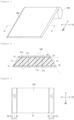
- Figure 1 is a cross-sectional view schematically showing a multilayer light-blocking film 100 and its web roll 200 in a first embodiment of the present invention
- Figure 2 is a cross-sectional view showing the main part of the multilayer light-blocking film 100 (the II-II cross section in Figure 1).
- Figure 3 is a plan view of the multilayer light-blocking film 100.
- This multilayer light-blocking film 100 comprises at least a substrate film 11, a first black light-blocking layer 21 provided on one major surface 11a side of this substrate film 11, and a second black light-blocking layer 31 provided on the other major surface 11b side.
- the multilayer light-blocking film 100 has a multilayer structure (three-layer structure) in which the black light-blocking layer 21, the substrate film 11, and the black light-blocking layer 31 are at least arranged in this order.
- this multilayer light-blocking film 100 By winding this multilayer light-blocking film 100 in the form of a cored or coreless roll, the rolled web 200 that is a wound body is formed.
- the black light-blocking layer 21 or 31 is directly placed on a surface (for example, the major surface 11a or the major surface 11b) of the substrate film 11 as in this embodiment, but a mode in which an optional layer (for example, a primer layer or an adhesive layer) is interposed between a surface of the substrate film 11 and the black light-blocking layer 21 or 31.
- an optional layer for example, a primer layer or an adhesive layer
- a multilayer structure comprising at least the first black light-blocking layer 21 and the second black light-blocking layer 31 means including not only a structure in which only the first black light-blocking layer 21 and the second black light-blocking layer 31 are directly layered, but the above-described three-layer structure and a multilayer structure of four or more layers in which an optional layer or optional layers are further provided in a three-layer structure.
- the type of the substrate film 11 is not particularly limited as long as it can support the black light-blocking layers 21 and 31.
- synthetic resin films are preferably used.
- Specific examples of the synthetic resin films include polyester films, ABS (acrylonitrile-butadiene-styrene) films, polyimide films, polystyrene films, and polycarbonate films.
- Acrylic, polyolefin-based, cellulosic, polysulfone-based, polyphenylene sulfide-based, polyethersulfone-based, and polyetheretherketone-based films can also be used.
- polyester films are preferably used as the substrate film 11.
- uniaxially or biaxially stretched films particularly biaxially stretched polyester films
- uniaxially or biaxially stretched polyimide films are particularly preferred.
- One of these can be used alone, and two or more of these can also be used in combination.
- the thickness of the substrate film 11 can be appropriately set according to the required performance and the application and is not particularly limited. From the viewpoint of weight reduction and film thinning, the thickness of the substrate film 11 is preferably 0.5 ⁇ m or more and 50 ⁇ m or less, more preferably 1 ⁇ m or more and 25 ⁇ m or less, further preferably 4 ⁇ m or more and 10 ⁇ m or less, and particularly preferably 5 ⁇ m or more and 7 ⁇ m or less. From the viewpoint of improving adhesiveness to the black light-blocking layers 21 and 31, the surfaces of the substrate film 11 can also be subjected to various known surface treatments such as anchor treatment and corona treatment as needed.
- Inclined end surfaces 12 are provided on the outer peripheral side surfaces (outer peripheral end surfaces) of the substrate film 11. Due to these inclined end surfaces 12, the cross-sectional structure of the substrate film 11 has a trapezoidal shape in which the lower base is longer than the upper base, so that the film width of the substrate film 11 increases from the black light-blocking layer 21 toward the black light-blocking layer 31 (see Figure 2 ).
- These inclined end surfaces 12 are provided so as to be exposed in a planar view from the normal direction of the major surface 11a of the substrate film 11 so as to be visible from the major surface 11a side of the substrate film 11 when the substrate film 11 is brought into a flat state as shown in Figure 2 (see Figure 3 ).
- the inclination angle ⁇ (depression angle ⁇ ) between the major surface 11a and the inclined end surface 12 of the substrate film 11 is set to be 10 to 87°.
- the inclination angle ⁇ is preferably 30 to 85°, more preferably 40 to 83°, and further preferably 45 to 80°.
- transparent or semitransparent protective layers or the like may be provided on the inclined end surfaces 12 for film end surface strengthening.
- the appearance of the substrate film 11 may be any of transparent, semitransparent, and opaque appearance and is not particularly limited.
- foamed synthetic resin films such as foamed polyester films, and synthetic resin films in which black pigments such as carbon black or other pigments are contained can also be used.
- the substrate film 11 preferably has a total light transmittance of 80.0 to 99.9%, more preferably 83.0 to 99.0%, and further preferably 85.0 to 99.0%.
- the black light-blocking layers 21 and 31 are light-blocking films having an optical density (OD) of 2.5 or more and a 60-degree glossiness (G60) of 5.0% or less.
- the optical density (OD) is a value obtained by measuring in accordance with JIS-K7651: 1988 using an optical densitometer (TD-904: GretagMacbeth) and a UV filter.
- the black light-blocking layers 21 and 31 each preferably have an optical density (OD) of 2.7 or more for a single layer.
- the optical density (OD) of the layered body is preferably 4.5 to 6.0, more preferably 5.0 to 6.0.
- the 60-degree glossiness is a value obtained by measuring the glossiness (specular glossiness) (%) of the surface of the black light-blocking layer 21 or 31 at incidence and acceptance angles of 60° in accordance with JIS-Z8741: 1997 using a digital variable angle glossmeter (UGV-5K: manufactured by Suga Test Instruments Co., Ltd.). From the viewpoint of suppressing the reflection of incident light and increasing light absorption properties, the black light-blocking layers 21 and 31 preferably have a 60-degree glossiness of 3.0% or less, more preferably 1.0% or less.
- the light-blocking film having an optical density of 2.5 or more and a 60-degree glossiness of 5.0% or less those known in the industry can be used, and the type of the light-blocking film is not particularly limited.
- a black light-blocking film containing at least a binder resin and a black pigment is preferably used as the black-based light-blocking film. This black light-blocking film will be described in detail below as an example.
- binder resin examples include, but are not particularly limited to, thermoplastic resins or thermosetting resins such as poly(meth)acrylic acid-based resins, polyester-based resins, polyvinyl acetate-based resins, polyvinyl chloride-based resins, polyvinyl butyral-based resins, cellulosic resins, polystyrene/polybutadiene resins, polyurethane-based resins, alkyd resins, acrylic resins, unsaturated polyester-based resins, epoxy ester-based resins, epoxy-based resins, epoxy acrylate-based resins, urethane acrylate-based resins, polyester acrylate-based resins, polyether acrylate-based resins, phenolic resins, melamine-based resins, urea-based resins, and diallyl phthalate-based resins.
- thermoplastic resins or thermosetting resins such as poly(meth)acrylic acid-based resins, polyester-based resins, polyvinyl
- thermosetting elastomers ultraviolet curable resins, electron beam curable resins, and the like can also be used. One of these can be used alone, and two or more of these can also be used in combination.
- the binder resin can be appropriately selected and used according to the required performance and the application. For example, in applications where heat resistance is required, thermosetting resins are preferred.
- the content (total amount) of the binder resin in the black light-blocking layer 21 or 31 is not particularly limited but is preferably 40 to 90% by mass, more preferably 50 to 85% by mass, and further preferably 60 to 80% by mass from the viewpoint of adhesiveness, light-blocking properties, scratch resistance, sliding properties, flatting properties, and the like.
- the black pigment colors the binder resin black to provide light-blocking properties.
- the black pigment include, but are not particularly limited to, black resin particles, titanium black, magnetite-based black, copper-iron-manganese-based black, titanium black, and carbon black.
- black resin particles, titanium black, and carbon black are preferred because of excellent concealing properties, and carbon black is more preferred.
- One of these can be used alone, and two or more of these can also be used in combination.
- the carbon black those made by various known manufacturing methods, such as oil furnace black, lamp black, channel black, gas furnace black, acetylene black, thermal black, and ketjen black, are known, but the type of the carbon black is not particularly limited. From the viewpoint of providing conductivity to the black light-blocking layer 21 or 31 to prevent electrostatic charging, conductive carbon black is particularly preferably used.
- the history of carbon black is old, and various grades of carbon black simple substances and carbon black dispersions are commercially available from, for example, Mitsubishi Chemical Corporation, Asahi Carbon Co., Ltd., MIKUNI COLOR LTD., RESINO COLOR INDUSTRY CO., LTD., Cabot, and DEGUSSA.
- the carbon black should be appropriately selected from among these according to the required performance and the application.
- the particle size of the carbon black can be appropriately set according to the required performance and the like and is not particularly limited.
- the average particle diameter D 50 of the carbon black is preferably 0.01 to 2.0 ⁇ m, more preferably 0.05 to 0.1 ⁇ m, and further preferably 0.08 to 0.5 ⁇ m.
- the average particle diameter herein means a volume-based median diameter (D 50 ) measured by a laser diffraction particle size distribution measuring apparatus (for example, SHIMADZU CORPORATION: SALD-7000).
- the content (total amount) of the black pigment in the black light-blocking layer 21 or 31 is not particularly limited but is preferably 10 to 60% by mass, more preferably 15 to 50% by mass, and further preferably 20 to 40% by mass in terms of solids based on all resin components contained in the black light-blocking layer 21 or 31 (phr) from the viewpoint of dispersibility, film-forming properties, handling properties, adhesiveness, slip properties, flatting properties, abrasion resistance, and the like.
- the thicknesses of the black light-blocking layers 21 and 31 can be appropriately set according to the required performance and the application and are not particularly limited. From the viewpoint of high optical density, weight reduction, and film thinning, the thicknesses of the black light-blocking layers 21 and 31 are each preferably 0.1 ⁇ m or more, more preferably 0.2 ⁇ m or more, further preferably 0.5 ⁇ m or more, and particularly preferably 1 ⁇ m or more and preferably 15 ⁇ m or less, more preferably 12 ⁇ m or less, further preferably 9 ⁇ m or less, and particularly preferably 6 ⁇ m or less on the upper limit side.
- One feature of the multilayer light-blocking film 100 in this embodiment is that from a human engineering approach, it is configured so that the black light-blocking layer 21 and the black light-blocking layer 31 have different 60-degree glossinesses (G60). By differentiating the 60-degree glossiness in this manner, the front and back of the multilayer light-blocking film 100 can be discriminated in a noncontact manner, that is, visually, based on the difference in glossy feeling, or luster between the black light-blocking layer 21 and the black light-blocking layer 31.
- G60 60-degree glossinesses
- the difference between the 60-degree glossiness of the black light-blocking layer 21 and the 60-degree glossiness of the black light-blocking layer 31 should be appropriately set considering the balance of discriminability and the blackness (light-blocking properties) and is 1.0 to 4.5%, more preferably 1.5 to 4.0%, and further preferably 2.0 to 3.0%.
- the 60-degree glossiness of the black light-blocking layer 21 should be 1.0 to 5.0, and the 60-degree glossiness of the black light-blocking layer 21 should be 0.1 to 0.9.
- the difference in lightness can be represented by the lightness L* in the CIE 1976 L*a*b* color system, and the difference in lightness L* is preferably 1 to 20, more preferably 2 to 15, and further preferably 3 to 10.
- the method for adjusting the 60-degree glossinesses and/or lightness indices L* of the black light-blocking layer 21 and the black light-blocking layer 31 includes, but is not particularly limited to, a method of differentiating the content of the black pigment between the black light-blocking layer 21 and the black light-blocking layer 31, a method of using black pigments having different blacknesses for the black light-blocking layer 21 and the black light-blocking layer 31, a method of using black pigments of different sizes for the black light-blocking layer 21 and the black light-blocking layer 31, a method of differentiating surface roughness between the black light-blocking layer 21 and the black light-blocking layer 31, and a method of using binder resins having different hues for the black light-blocking layer 21 and the black light-blocking layer 31. It is also possible to adjust lightness, hue, and/or saturation by blending various known additives used in light-blocking films. For these adjustment methods, the various methods can each be performed alone or can be performed in appropriate combination.
- inclined end surfaces 22 or 32 (outer peripheral end surfaces 22 or 32) having an inclination angle ⁇ corresponding to that of the above-described inclined end surfaces 12 are provided on both side surfaces (two places). These inclined end surfaces 22 and 32 are provided so as to be exposed in a planar view from the normal direction of the major surface 21a of the black light-blocking layer 21 so as to be visible from the major surface 21a side of the black light-blocking layer 21 when the black light-blocking layers 21 and 31 are brought into a flat state as shown in Figure 2 (see Figure 3 ).
- the inclination angle ⁇ between the major surface 21a of the black light-blocking layer 21 and the inclined end surface 22 or 32 is set to be 10 to 87°.
- transparent or semitransparent protective layers or the like may be provided on the inclined end surfaces 22 and 32 for film end surface strengthening.
- the inclination angle ⁇ of the inclined end surface 22 or 32 is not particularly limited but is preferably 10 to 87°, more preferably 35 to 85°, further preferably 40 to 83°, and particularly preferably 45 to 80° like the inclined end surface 12.
- the end surface strength tends to be easily maintained high, and the productivity tends to be easily improved.
- the black light-blocking layers 21 and 31 may contain various additives known in the industry. Specific examples thereof include, but are not particularly limited to, matting agents (flatting agents), lubricants, conductive agents, flame retardants, antimicrobial agents, fungicides, antioxidants, plasticizers, leveling agents, flow-adjusting agents, antifoaming agents, and dispersing agents.
- matting agents include, but are not particularly limited to, organic fine particles such as crosslinked polymethyl methacrylate particles and crosslinked polystyrene particles, and inorganic fine particles such as silica, magnesium aluminometasilicate, and titanium oxide.
- lubricants include, but are not particularly limited to, hydrocarbon-based lubricants such as polyethylene, paraffins, and waxes; fatty acid-based lubricants such as stearic acid and 12-hydroxystearic acid; amide-based lubricants such as stearic acid amide, oleic acid amide, and erucic acid amide; ester-based lubricants such as butyl stearate and stearic acid monoglyceride; alcohol-based lubricants; solid lubricants such as metallic soaps, talc, and molybdenum disulfide; silicone resin particles, and particles of fluororesins such as polytetrafluoroethylene waxes and polyvinylidene fluoride.
- hydrocarbon-based lubricants such as polyethylene, paraffins, and waxes
- fatty acid-based lubricants such as stearic acid and 12-hydroxystearic acid
- amide-based lubricants such as
- organic lubricants are preferably used.
- a sensitizer such as n-butylamine, triethylamine, or tri-n-butylphosphine
- an ultraviolet absorbing agent may be used.
- One of these can be used alone, and two or more of these can also be used in combination.
- the content of these is not particularly limited, but the content of each is generally preferably 0.01 to 5% by mass in terms of solids based on all resin components contained in the black light-blocking layer 21 or 31.
- the black light-blocking layers 21 and 31 preferably have a visible light reflectance of 10.0% or less.
- the visible light reflectance means relative total light reflectance when light is allowed to enter at an incidence angle of 8° to the black light-blocking layer 21 or 31 using a spectrophotometer (spectrophotometer SolidSpec-3700 manufactured by SHIMADZU CORPORATION, or the like) and barium sulfate as a standard plate.
- the visible light reflectances of the black light-blocking layers 21 and 31 are more preferably 8% or less, further preferably 6% or less, and particularly preferably 4% or less.
- the difference in visible light reflectance between the black light-blocking layer 21 and the black light-blocking layer 31 is preferably 1% or more.
- the diffuse reflectance in the range of infrared light (800 to 1000 nm) other than visible light is preferably 10% or less, more preferably 8% or less, further preferably 6% or less, and particularly preferably 4% or less.
- the black light-blocking layers 21 and 31 preferably have a surface resistivity of less than 1.0 ⁇ 10 8 ⁇ , more preferably less than 1.0 ⁇ 10 5 ⁇ , and further preferably less than 5.0 ⁇ 10 4 ⁇ from the viewpoint of having sufficient antistatic performance.
- the surface resistivity is a value measured in accordance with JIS-K6911: 1995.
- the method for manufacturing the multilayer light-blocking film 100 is not particularly limited as long as one having the above-described configuration is obtained. From the viewpoint of manufacturing the black light-blocking layers 21 and 31 on the substrate film 11 with good reproducibility, simply, and at low cost, conventionally known application methods such as doctor coating, dip coating, roll coating, bar coating, die coating, blade coating, air knife coating, kiss coating, spray coating, and spin coating are preferably used.
- the black light-blocking layer 21 or 31 can be formed on the substrate film 11 by applying onto a major surface of the substrate film 11 an application liquid containing in a solvent the binder resin and the black pigment described above and additives as optional components blended as needed, drying the application liquid, and then performing heat treatment, pressurization treatment, and the like as needed.
- ketone-based solvents such as methyl ethyl ketone, methyl isobutyl ketone, and cyclohexanone
- ester-based solvents such as methyl acetate, ethyl acetate, and butyl acetate
- ether-based solvents such as methyl cellosolve and ethyl cellosolve
- alcohol-based solvents such as methyl alcohol, ethyl alcohol, and isopropyl alcohol, and mixed solvents thereof, and the like
- anchor treatment, corona treatment, or the like can also be performed as needed.
- an intermediate layer such as a primer layer or an adhesive layer can also be provided between the substrate film 11 and the black light-blocking layer 21 or 31 as needed.
- the multilayer light-blocking film 100 having the desired shape can also be simply obtained by various known forming methods such as compression molding, injection molding, blow molding, transfer molding, and extrusion. Once a sheet shape is formed, then vacuum forming, pressure forming, or the like can also be performed.
- the method for forming the inclined end surfaces 12, 22, and 32 is not particularly limited either.
- the inclined end surfaces 12, 22, and 32 having any inclination angle ⁇ can be made by appropriately applying various known methods.
- the inclined end surfaces 12, 22, and 32 can be simply provided by providing a multilayer light-blocking film in which the black light-blocking layer 21 and the black light-blocking layer 31 are provided on the substrate film 11, and cutting off (cutting out) its outer peripheral side surfaces at the above-described inclination angle.
- the inclined end surfaces 22 and 32 are unnecessary, it is recommended to provide the substrate film 11 previously provided with the inclined end surfaces 12 having any inclination angle ⁇ and provide the black light-blocking layer 21 and the black light-blocking layer 31 on this substrate film 11.
- the first black light-blocking layer 21 and the second black light-blocking layer 31 having an optical density of 2.5 or more and a 60-degree glossiness of 5.0% or less are adopted. Therefore, by using these as a light-blocking member for optical equipment such as a lens unit or a camera module, unnecessary incident light and reflected light can be removed, the occurrence of halation, lens flare, a ghost, and the like can be prevented, and the image quality of a picked-up image can be improved.
- the first black light-blocking layer 21 and the second black light-blocking layer 31 have different 60-degree glossinesses and therefore the discrimination of the front and back surfaces can be easily performed in a noncontact manner, that is, visually, based on the difference in glossy feeling or luster between the first black light-blocking layer 21 and the second black light-blocking layer 31.
- the inclined end surfaces 12 visibly exposed in a planar view are recognizable as bright portions having a glossy feeling at the outer peripheral edges of the film, and therefore the discrimination of the front and back surfaces of the multilayer light-blocking film 100 can be especially easily performed in a noncontact manner, that is, visually. This is due to the difference 60-degree glossiness between the first black light-blocking layer 21 or the second black light-blocking layer 31 and the inclined end surfaces 12 (the substrate film 11).
- the inclined end surfaces 12 function effectively.
- the inclined end surfaces 12 (the substrate film 11) are clearly recognizable as bright portions having a glossy feeling, even with a little light, due to the difference from the first black light-blocking layer 21 and the second black light-blocking layer 31.
- the discrimination of the front and back surfaces can also be performed by directly touching the inclined end surface 12 with fingers or the like to confirm its inclination direction.
- the present invention can be carried out by making changes.
- the inclined end surfaces 12 may be provided without providing the inclined end surfaces 22 and 32.
- the inclined end surface 12 should be provided on at least part of the outer peripheral side surfaces of the substrate film 11.
- the inclined end surface 12 may be provided on both side surfaces (two places) of the substrate film 11 so as to extend in the MD direction of the multilayer light-blocking film 100 as in this embodiment, or provided on one side surface (one place) or both side surfaces (two places) of the substrate film 11 so as to extend in the TD direction of the substrate film 11.
- the inclined end surfaces 12 may be provided over all of the outer peripheral side surfaces (entire periphery) of the substrate film 11.
- the inclined end surfaces 12 extending in the MD direction and/or the TD direction may be continuously formed as in this embodiment and may be intermittently formed.
- FIG 4 is an exploded perspective view schematically showing a lens unit 41 and a camera module 51 in a second embodiment of the present invention.
- the lens unit 41 is composed of a lens group 42 (lenses 42A, 42B, 42C, 42D, and 42E), a multistage cylindrical holder 43, and light-blocking rings 100A, 100B, and 100C for optical equipment (the multilayer light-blocking films 100) as light-blocking spacers.
- a plurality of height difference portions 43a, 43b, and 43c are provided in the inner peripheral portion of the holder 43.
- the lens group 42 and the light-blocking rings 100A, 100B, and 100C for optical equipment are housed and disposed at predetermined positions in the holder 43 in a state of being coaxially (on the same optical axis) disposed and stacked.
- the lenses 42A, 42B, 42C, 42D, and 42E various lenses such as convex lenses and concave lenses can be used, and their curved surfaces may be spherical or aspherical.
- the camera module 51 is composed of the above-described lens unit 41 and an image pickup device 44 such as a CCD image sensor or a CMOS image sensor that is disposed on the optical axis of this lens unit 41 and picks up an image of an object through the lens unit 41.
- an image pickup device 44 such as a CCD image sensor or a CMOS image sensor that is disposed on the optical axis of this lens unit 41 and picks up an image of an object through the lens unit 41.
- Figure 5 is a cross-sectional view schematically showing the light-blocking ring 100A for optical equipment.
- the light-blocking ring 100A for optical equipment is obtained by stamping the multilayer light-blocking film 100 in the first embodiment described above into a ring shape (hollow tubular shape). Therefore, the light-blocking ring 100A for optical equipment has the same multilayer structure as the multilayer light-blocking film 100 in the first embodiment described above.
- the light-blocking ring 100A for optical equipment is a light-blocking plate whose outer shape is a ring shape (hollow tubular shape) in which a cylindrical hollow portion S is provided at a generally central position in a planar view.
- the above-described inclined end surfaces 12, 22, and 32 are not provided on the outer peripheral side surface of the light-blocking ring 100A for optical equipment, and these outer peripheral side surfaces are formed in a rectangular shape in a cross-sectional view.
- the inclination angle ⁇ of the outer peripheral end surface is 90°.
- the light-blocking ring 100A for optical equipment in this embodiment inclined end surfaces 13, 23, and 33 corresponding to the above-described inclined end surfaces 12, 22, and 32 are provided on the inner peripheral end surface.
- the light-blocking rings 100B and 100C for optical equipment have the same configuration as the light-blocking ring 100A for optical equipment except that the size of the outer diameter and the size of the outer diameter of the hollow portion S are each different, and redundant description is omitted here.
- the first black light-blocking layer 21 and the second black light-blocking layer 31 having an optical density of 2.5 or more and a 60-degree glossiness of 5.0% or less are adopted. Therefore, by using these as light-blocking members for optical equipment such as a lens unit or a camera module, unnecessary incident light and reflected light can be removed, the occurrence of halation, lens flare, a ghost, and the like can be prevented, and the image quality of a picked-up image can be improved.
- the first black light-blocking layer 21 and the second black light-blocking layer 31 have different 60-degree glossinesses and therefore the discrimination of the front and back surfaces of the light-blocking rings 100A, 100B, and 100C for optical equipment can be easily performed in a noncontact manner, that is, visually, based on the difference in glossy feeling or luster between the first black light-blocking layer 21 and the second black light-blocking layer 31. Therefore, for the lens unit 41 and the camera module 51 using these light-blocking rings 100A, 100B, and 100C for optical equipment, also during their storage and incorporation, manufacturing failure such as poor incorporation based on the false recognition of the front and back surfaces is inhibited.
- the inclined end surfaces 13, 23, and 33 are provided, and the discriminability of the black light-blocking layers 21 and 31 is further increased.
- the inclined end surfaces 13, 23, and 33 are provided on the end surface on the optical axis side (inner peripheral end surface) in this manner, unnecessary reflected light can be removed, the occurrence of halation, lens flare, a ghost, and the like can be prevented, and the image quality of a picked-up image can be improved.
- the present invention can be carried out by making changes.
- the outer shape of the multilayer light-blocking film 100 for example, any shape such as a polygonal shape such as a rectangular shape, a square shape, or a hexagonal shape, an elliptical shape, or an irregular shape in a planar view can be adopted.
- the hollow portion S of the light-blocking ring 100A, 100B, or 100C for optical equipment is formed in a circular shape in a planar view in this embodiment, but its outer shape is not particularly limited.
- any shape such as a polygonal shape such as a rectangular shape, a square shape, or a hexagonal shape, an elliptical shape, or an irregular shape in a planar view can be adopted.
- the above-described inclined end surfaces 12, 22, and 32 are not provided, but either one or both of the inclined end surface 12 and the inclined end surfaces 22 and 32 can be appropriately provided as needed.
- the present invention can be widely and effectively used as a high-performance light-blocking member in the precision machine field, the semiconductor field, the optical equipment field, electronic equipment, and the like.
- the present invention can be particularly effectively used as a light-blocking member used in a lens unit, a camera module, or the like mounted in a high-performance single-lens reflex camera, a compact camera, a video camera, a cellular phone, a projector, or the like.
Landscapes
- Physics & Mathematics (AREA)
- General Physics & Mathematics (AREA)
- Optics & Photonics (AREA)
- Chemical & Material Sciences (AREA)
- Medicinal Chemistry (AREA)
- Chemical Kinetics & Catalysis (AREA)
- Health & Medical Sciences (AREA)
- Polymers & Plastics (AREA)
- Organic Chemistry (AREA)
- Optical Elements Other Than Lenses (AREA)
- Lens Barrels (AREA)
- Blocking Light For Cameras (AREA)
- Diaphragms For Cameras (AREA)
Claims (10)
- Mehrschichtiger lichtblockierender Film (100) für optische Geräte, umfassend:eine Mehrschichtstruktur, die mindestens eine erste schwarze lichtblockierende Schicht (21), die auf der Vorderseite der Mehrschichtstruktur angeordnet ist, und eine zweite schwarze lichtblockierende Schicht (31), die auf der Rückseite der Mehrschichtstruktur angeordnet ist, umfasst, wobeidie erste schwarze lichtblockierende Schicht und die zweite schwarze lichtblockierende Schicht jeweils eine optische Dichte von 2,5 oder mehr und einen 60-Grad-Glanz von 5,0 % oder weniger aufweisen,wobei der mehrschichtige lichtblockierende Film dadurch gekennzeichnet ist, dassdie erste schwarze lichtblockierende Schicht einen 60-Grad-Glanz aufweist, der von einem 60-Grad-Glanz der zweiten schwarzen lichtblockierenden Schicht verschieden ist, wobei eine Differenz zwischen dem 60-Grad-Glanz der ersten schwarzen lichtblockierenden Schicht und dem 60-Grad-Glanz der zweiten schwarzen lichtblockierenden Schicht 1,0 bis 4,5% beträgt.
- Mehrschichtiger lichtblockierender Film (100) für optische Geräte nach Anspruch 1, wobeidie erste schwarze lichtblockierende Schicht (21) und/oder die zweite schwarze lichtblockierende Schicht (31) geneigte Endflächen (22, 32) aufweisen, so dass eine Filmbreite in von der ersten schwarzen lichtblockierenden Schicht zur zweiten schwarzen lichtblockierenden Schicht hin ansteigt, unddie geneigte Endfläche in einer aus einer normalen Richtung einer Hauptoberfläche (21a) der ersten schwarzen lichtblockierenden Schicht gesehenen ebenen Ansicht freiliegt.
- Mehrschichtiger lichtblockierender Film (100) für optische Geräte nach Anspruch 2, wobei
ein Neigungswinkel (θ) zwischen der Hauptoberfläche (21a) der ersten schwarzen lichtblockierenden Schicht (21) und der geneigten Endfläche (22) 10 bis 87° beträgt. - Mehrschichtiger lichtblockierender Film (100) für optische Geräte nach einem der Ansprüche 1 bis 3, wobei
die erste schwarze lichtblockierende Schicht (21) und die zweite schwarze lichtblockierende Schicht (31) einen hohlen Abschnitt (S) und geneigte Endflächen (21, 31), die auf der inneren peripheren Endfläche des hohlen Abschnitts vorgesehen sind, aufweisen. - Mehrschichtiger lichtblockierender Film (100) für optische Geräte nach einem der Ansprüche 1 bis 4, umfassend:
eine mehrschichtige Struktur, die mindestens einen Substratfilm (11) umfasst, wobei die erste schwarze lichtblockierende Schicht (21) auf einer Hauptoberflächenseite des Substratfilms vorgesehen ist und die zweite schwarze lichtblockierende Schicht (31) auf der anderen Hauptoberflächenseite des Substratfilms vorgesehen ist. - Mehrschichtiger lichtblockierender Film (100) für optische Geräte nach Anspruch 5, wobei
der Substratfilm (11) eine Gesamtlichtdurchlässigkeit von 80,0 bis 99,9 % aufweist. - Mehrschichtiger lichtblockierender Film (100) für optische Geräte nach Anspruch 5 oder 6, wobei
der Substratfilm (11) eine Dicke von 0,5 µm oder mehr und 50 µm oder weniger aufweist. - Lichtblockierender Ring (100A) für optische Geräte, der eine ringförmige Außenform aufweist und den mehrschichtigen lichtblockierenden Film (100) für optische Geräte nach einem der Ansprüche 1, 2, 4 oder 5 umfasst.
- Linseneinheit, umfassend mehrere Linsen und mindestens eine oder mehrere lichtblockierende Platten, die in Richtung der optischen Achse der Linsen übereinander angeordnet sind, wobei
mindestens eine oder mehrere der lichtblockierenden Platten den mehrschichtigen lichtblockierenden Film (100) für optische Geräte nach einem der Ansprüche 1 bis 7 und/oder den lichtblockierenden Ring (100A) für optische Geräte nach Anspruch 8 umfassen. - Kameramodul, umfassend mindestens: eine Linseneinheit, die mehrere Linsen und mindestens eine oder mehrere lichtblockierende Platten, die in einer optischen Achsenrichtung der Linsen übereinander angeordnet sind, umfasst; und eine Bildaufnahmevorrichtung zum Aufnehmen eines Bildes eines Objekts durch die Linseneinheit, wobei
mindestens eine oder mehrere der lichtblockierenden Platten den mehrschichtigen lichtblockierenden Film (100) für optische Geräte nach einem der Ansprüche 1 bis 7 und/oder den lichtblockierenden Ring (100A) für optische Geräte nach Anspruch 8 umfassen.
Priority Applications (1)
| Application Number | Priority Date | Filing Date | Title |
|---|---|---|---|
| EP23211925.5A EP4307044B1 (de) | 2016-10-06 | 2017-09-25 | Laminierter lichtabschirmender film und lichtabschirmender ring für optische vorrichtung damit, linseneinheit und kameramodul |
Applications Claiming Priority (2)
| Application Number | Priority Date | Filing Date | Title |
|---|---|---|---|
| JP2016198372A JP6314194B2 (ja) | 2016-10-06 | 2016-10-06 | 光学機器用積層遮光フィルム、並びに、これを用いた光学機器用遮光リング、レンズユニット及びカメラモジュール |
| PCT/JP2017/034535 WO2018066401A1 (ja) | 2016-10-06 | 2017-09-25 | 積層遮光フィルム、並びに、これを用いた光学機器用遮光リング、レンズユニット及びカメラモジュール |
Related Child Applications (2)
| Application Number | Title | Priority Date | Filing Date |
|---|---|---|---|
| EP23211925.5A Division-Into EP4307044B1 (de) | 2016-10-06 | 2017-09-25 | Laminierter lichtabschirmender film und lichtabschirmender ring für optische vorrichtung damit, linseneinheit und kameramodul |
| EP23211925.5A Division EP4307044B1 (de) | 2016-10-06 | 2017-09-25 | Laminierter lichtabschirmender film und lichtabschirmender ring für optische vorrichtung damit, linseneinheit und kameramodul |
Publications (3)
| Publication Number | Publication Date |
|---|---|
| EP3525014A1 EP3525014A1 (de) | 2019-08-14 |
| EP3525014A4 EP3525014A4 (de) | 2020-06-17 |
| EP3525014B1 true EP3525014B1 (de) | 2024-01-03 |
Family
ID=61830843
Family Applications (2)
| Application Number | Title | Priority Date | Filing Date |
|---|---|---|---|
| EP17858240.9A Active EP3525014B1 (de) | 2016-10-06 | 2017-09-25 | Laminierter lichtabschirmender film und lichtabschirmender ring für optische vorrichtung damit, linseneinheit und kameramodul |
| EP23211925.5A Active EP4307044B1 (de) | 2016-10-06 | 2017-09-25 | Laminierter lichtabschirmender film und lichtabschirmender ring für optische vorrichtung damit, linseneinheit und kameramodul |
Family Applications After (1)
| Application Number | Title | Priority Date | Filing Date |
|---|---|---|---|
| EP23211925.5A Active EP4307044B1 (de) | 2016-10-06 | 2017-09-25 | Laminierter lichtabschirmender film und lichtabschirmender ring für optische vorrichtung damit, linseneinheit und kameramodul |
Country Status (7)
| Country | Link |
|---|---|
| US (1) | US20190227202A1 (de) |
| EP (2) | EP3525014B1 (de) |
| JP (1) | JP6314194B2 (de) |
| KR (2) | KR102525968B1 (de) |
| CN (1) | CN109791231B (de) |
| TW (1) | TWI736685B (de) |
| WO (1) | WO2018066401A1 (de) |
Cited By (1)
| Publication number | Priority date | Publication date | Assignee | Title |
|---|---|---|---|---|
| EP3779524A4 (de) * | 2018-04-11 | 2022-04-13 | Kimoto Co., Ltd. | Lichtabschirmender film für optische ausrüstung und lichtabschirmender laminierter film für optische ausrüstung, lichtabschirmender ring für optische ausrüstung mit verwendung davon, blendenelement für optische ausrüstung, verschlusselement für optische ausrüstung, objektiveinheit und kameramodul |
Families Citing this family (11)
| Publication number | Priority date | Publication date | Assignee | Title |
|---|---|---|---|---|
| US10668693B2 (en) * | 2016-11-15 | 2020-06-02 | Largan Precision Co., Ltd. | Composite light blocking sheet, imaging lens assembly and electronic device |
| JP6368445B1 (ja) * | 2017-03-27 | 2018-08-01 | 株式会社きもと | 積層遮光フィルム、並びに、これを用いた光学機器用遮光リング、レンズユニット及びカメラモジュール |
| TWI676852B (zh) * | 2018-10-31 | 2019-11-11 | 白金科技股份有限公司 | 遮光片 |
| JP2020106725A (ja) * | 2018-12-28 | 2020-07-09 | マクセル株式会社 | 遮光板、レンズユニットおよびカメラモジュール |
| CN118011710A (zh) * | 2019-07-19 | 2024-05-10 | 凸版印刷株式会社 | 遮光板、照相机单元以及电子仪器 |
| JP7232918B2 (ja) * | 2019-08-09 | 2023-03-03 | 株式会社ダイセル | 遮光性フィルム及び遮光性フィルムの製造方法 |
| WO2021060004A1 (ja) * | 2019-09-24 | 2021-04-01 | 三菱ケミカル株式会社 | ポリエステルフィルム |
| DE102020100972B4 (de) | 2020-01-16 | 2024-06-13 | Sick Ag | Optoelektronischer Sensor und Verfahren zur Herstellung eines optoelektronischen Sensors |
| TWI812062B (zh) | 2021-11-05 | 2023-08-11 | 大立光電股份有限公司 | 光學鏡頭及電子裝置 |
| TWI821864B (zh) | 2021-12-29 | 2023-11-11 | 大立光電股份有限公司 | 成像鏡頭、遮光片及電子裝置 |
| JP7564600B1 (ja) | 2024-07-18 | 2024-10-09 | 株式会社ニチベイパーツ | 遮光リング製造方法 |
Citations (2)
| Publication number | Priority date | Publication date | Assignee | Title |
|---|---|---|---|---|
| US20070236627A1 (en) * | 2006-04-06 | 2007-10-11 | Samsung Electronics Co., Ltd., | Diffusion plate, backlight assembly, liquid crystal display having the same and method of forming thereof |
| EP2573595A1 (de) * | 2010-05-20 | 2013-03-27 | Toyobo Co., Ltd. | Lichtabschirmender film |
Family Cites Families (22)
| Publication number | Priority date | Publication date | Assignee | Title |
|---|---|---|---|---|
| JPH042780A (ja) * | 1990-04-18 | 1992-01-07 | Sumitomo Metal Ind Ltd | 高耐食性着色表面処理鋼板 |
| JPH09274218A (ja) | 1996-04-05 | 1997-10-21 | Dainippon Printing Co Ltd | 遮光性フィルム |
| JP3929546B2 (ja) * | 1996-09-20 | 2007-06-13 | ソマール株式会社 | 反射防止性カメラ及びそれに用いられる反射防止用フィルム |
| JP3456408B2 (ja) * | 1997-05-12 | 2003-10-14 | トヨタ自動車株式会社 | 内燃機関の排気浄化装置 |
| JPH11301117A (ja) * | 1997-09-29 | 1999-11-02 | Konica Corp | 転写箔及びそれを用いた画像形成材料 |
| JP3143608B2 (ja) * | 1998-07-13 | 2001-03-07 | セイコーエプソン株式会社 | 投射型表示装置 |
| JP2005007864A (ja) * | 2003-05-23 | 2005-01-13 | Seiko Epson Corp | 画像保護フィルム並びにこれを用いた画像保護方法及びオーバーコート記録物 |
| CN100498381C (zh) | 2004-08-10 | 2009-06-10 | 木本股份有限公司 | 光学设备用遮光部件 |
| JP4292130B2 (ja) * | 2004-09-17 | 2009-07-08 | ソニー株式会社 | 遮光部材、撮像装置および遮光部材の製造方法 |
| JP2008176188A (ja) * | 2007-01-22 | 2008-07-31 | Kyocera Mita Corp | 画像形成装置 |
| JP4918380B2 (ja) * | 2007-03-13 | 2012-04-18 | ソマール株式会社 | 遮光フィルム及びその製造方法 |
| JP5228397B2 (ja) * | 2007-04-10 | 2013-07-03 | 住友金属鉱山株式会社 | 耐熱遮光フィルムとその製造方法、及びそれを用いた絞り又は光量調整装置 |
| JP2009003315A (ja) * | 2007-06-25 | 2009-01-08 | Toray Ind Inc | 遮光シート |
| US20100226016A1 (en) * | 2007-07-25 | 2010-09-09 | Nippon Shokubai Co., Ltd. | Light-shielding film |
| US7857450B1 (en) * | 2008-02-04 | 2010-12-28 | Albert John Hofeldt | Hand-held device for contrast and multifunction vision testing |
| JP2010069760A (ja) * | 2008-09-19 | 2010-04-02 | Kyocera Chemical Corp | フレキシブル基板材料用離型シート、カバーレイ及びボンディングシート |
| JP5725842B2 (ja) * | 2010-12-21 | 2015-05-27 | 株式会社きもと | 光学機器用遮光部材 |
| US9383484B2 (en) * | 2011-03-28 | 2016-07-05 | Kimoto Co. Ltd. | Light-shielding material for optical instrument |
| JP2012208391A (ja) * | 2011-03-30 | 2012-10-25 | Fujifilm Corp | 遮光材料付き光学レンズの製造方法、遮光材料形成用インク |
| CN105190390B (zh) * | 2013-03-26 | 2018-07-06 | 富士胶片株式会社 | 光学透镜及其制造方法及透镜单元、摄像模块、电子设备 |
| CN104297887A (zh) * | 2013-07-17 | 2015-01-21 | 玉晶光电(厦门)有限公司 | 摄影镜头及用于摄影镜头的垫圈 |
| WO2016006324A1 (ja) * | 2014-07-09 | 2016-01-14 | 株式会社きもと | 光学機器用遮光材及びその製造方法 |
-
2016
- 2016-10-06 JP JP2016198372A patent/JP6314194B2/ja active Active
-
2017
- 2017-09-25 EP EP17858240.9A patent/EP3525014B1/de active Active
- 2017-09-25 EP EP23211925.5A patent/EP4307044B1/de active Active
- 2017-09-25 KR KR1020197010498A patent/KR102525968B1/ko active Active
- 2017-09-25 WO PCT/JP2017/034535 patent/WO2018066401A1/ja not_active Ceased
- 2017-09-25 KR KR1020227045097A patent/KR20230003446A/ko not_active Ceased
- 2017-09-25 CN CN201780061378.4A patent/CN109791231B/zh active Active
- 2017-09-25 US US16/339,994 patent/US20190227202A1/en not_active Abandoned
- 2017-10-03 TW TW106134137A patent/TWI736685B/zh active
Patent Citations (2)
| Publication number | Priority date | Publication date | Assignee | Title |
|---|---|---|---|---|
| US20070236627A1 (en) * | 2006-04-06 | 2007-10-11 | Samsung Electronics Co., Ltd., | Diffusion plate, backlight assembly, liquid crystal display having the same and method of forming thereof |
| EP2573595A1 (de) * | 2010-05-20 | 2013-03-27 | Toyobo Co., Ltd. | Lichtabschirmender film |
Cited By (1)
| Publication number | Priority date | Publication date | Assignee | Title |
|---|---|---|---|---|
| EP3779524A4 (de) * | 2018-04-11 | 2022-04-13 | Kimoto Co., Ltd. | Lichtabschirmender film für optische ausrüstung und lichtabschirmender laminierter film für optische ausrüstung, lichtabschirmender ring für optische ausrüstung mit verwendung davon, blendenelement für optische ausrüstung, verschlusselement für optische ausrüstung, objektiveinheit und kameramodul |
Also Published As
| Publication number | Publication date |
|---|---|
| US20190227202A1 (en) | 2019-07-25 |
| EP3525014A4 (de) | 2020-06-17 |
| KR20190057329A (ko) | 2019-05-28 |
| TWI736685B (zh) | 2021-08-21 |
| CN109791231B (zh) | 2021-06-29 |
| JP6314194B2 (ja) | 2018-04-18 |
| WO2018066401A1 (ja) | 2018-04-12 |
| KR102525968B1 (ko) | 2023-04-25 |
| EP4307044B1 (de) | 2026-04-08 |
| TW201833650A (zh) | 2018-09-16 |
| CN109791231A (zh) | 2019-05-21 |
| EP3525014A1 (de) | 2019-08-14 |
| EP4307044A2 (de) | 2024-01-17 |
| JP2018060098A (ja) | 2018-04-12 |
| EP4307044A3 (de) | 2024-03-20 |
| KR20230003446A (ko) | 2023-01-05 |
Similar Documents
| Publication | Publication Date | Title |
|---|---|---|
| EP4307044B1 (de) | Laminierter lichtabschirmender film und lichtabschirmender ring für optische vorrichtung damit, linseneinheit und kameramodul | |
| EP3637156B1 (de) | Mehrfachschicht lichtabschirmfolie und lichtabschirmring für optische ausrüstung, linseneinheit und kameramodul mit verwendung davon | |
| JP7685468B2 (ja) | 光学機器用遮光フィルム及び光学機器用積層遮光フィルム、並びに、これを用いた光学機器用遮光リング、光学機器用絞り部材、光学機器用シャッター部材、レンズユニット及びカメラモジュール | |
| EP3605156B1 (de) | Laminierte abschirmfolie und abschirmring für optische vorrichtung, linseneinheit und kameramodul damit | |
| JP2018088013A (ja) | 光学機器用積層遮光フィルム、並びに、これを用いた光学機器用遮光リング、レンズユニット及びカメラモジュール |
Legal Events
| Date | Code | Title | Description |
|---|---|---|---|
| STAA | Information on the status of an ep patent application or granted ep patent |
Free format text: STATUS: THE INTERNATIONAL PUBLICATION HAS BEEN MADE |
|
| PUAI | Public reference made under article 153(3) epc to a published international application that has entered the european phase |
Free format text: ORIGINAL CODE: 0009012 |
|
| STAA | Information on the status of an ep patent application or granted ep patent |
Free format text: STATUS: REQUEST FOR EXAMINATION WAS MADE |
|
| 17P | Request for examination filed |
Effective date: 20190408 |
|
| AK | Designated contracting states |
Kind code of ref document: A1 Designated state(s): AL AT BE BG CH CY CZ DE DK EE ES FI FR GB GR HR HU IE IS IT LI LT LU LV MC MK MT NL NO PL PT RO RS SE SI SK SM TR |
|
| AX | Request for extension of the european patent |
Extension state: BA ME |
|
| DAV | Request for validation of the european patent (deleted) | ||
| DAX | Request for extension of the european patent (deleted) | ||
| A4 | Supplementary search report drawn up and despatched |
Effective date: 20200515 |
|
| RIC1 | Information provided on ipc code assigned before grant |
Ipc: G03B 9/02 20060101ALI20200511BHEP Ipc: G02B 5/00 20060101AFI20200511BHEP Ipc: G02B 7/02 20060101ALI20200511BHEP Ipc: G03B 11/00 20060101ALI20200511BHEP |
|
| STAA | Information on the status of an ep patent application or granted ep patent |
Free format text: STATUS: EXAMINATION IS IN PROGRESS |
|
| 17Q | First examination report despatched |
Effective date: 20220211 |
|
| GRAP | Despatch of communication of intention to grant a patent |
Free format text: ORIGINAL CODE: EPIDOSNIGR1 |
|
| STAA | Information on the status of an ep patent application or granted ep patent |
Free format text: STATUS: GRANT OF PATENT IS INTENDED |
|
| INTG | Intention to grant announced |
Effective date: 20230829 |
|
| GRAS | Grant fee paid |
Free format text: ORIGINAL CODE: EPIDOSNIGR3 |
|
| GRAA | (expected) grant |
Free format text: ORIGINAL CODE: 0009210 |
|
| STAA | Information on the status of an ep patent application or granted ep patent |
Free format text: STATUS: THE PATENT HAS BEEN GRANTED |
|
| AK | Designated contracting states |
Kind code of ref document: B1 Designated state(s): AL AT BE BG CH CY CZ DE DK EE ES FI FR GB GR HR HU IE IS IT LI LT LU LV MC MK MT NL NO PL PT RO RS SE SI SK SM TR |
|
| P01 | Opt-out of the competence of the unified patent court (upc) registered |
Effective date: 20231123 |
|
| REG | Reference to a national code |
Ref country code: GB Ref legal event code: FG4D |
|
| REG | Reference to a national code |
Ref country code: DE Ref legal event code: R096 Ref document number: 602017078193 Country of ref document: DE |
|
| REG | Reference to a national code |
Ref country code: CH Ref legal event code: EP |
|
| REG | Reference to a national code |
Ref country code: IE Ref legal event code: FG4D |
|
| REG | Reference to a national code |
Ref country code: LT Ref legal event code: MG9D |
|
| PG25 | Lapsed in a contracting state [announced via postgrant information from national office to epo] |
Ref country code: ES Free format text: LAPSE BECAUSE OF FAILURE TO SUBMIT A TRANSLATION OF THE DESCRIPTION OR TO PAY THE FEE WITHIN THE PRESCRIBED TIME-LIMIT Effective date: 20240103 |
|
| PG25 | Lapsed in a contracting state [announced via postgrant information from national office to epo] |
Ref country code: ES Free format text: LAPSE BECAUSE OF FAILURE TO SUBMIT A TRANSLATION OF THE DESCRIPTION OR TO PAY THE FEE WITHIN THE PRESCRIBED TIME-LIMIT Effective date: 20240103 |
|
| REG | Reference to a national code |
Ref country code: NL Ref legal event code: MP Effective date: 20240103 |
|
| REG | Reference to a national code |
Ref country code: AT Ref legal event code: MK05 Ref document number: 1647370 Country of ref document: AT Kind code of ref document: T Effective date: 20240103 |
|
| PG25 | Lapsed in a contracting state [announced via postgrant information from national office to epo] |
Ref country code: NL Free format text: LAPSE BECAUSE OF FAILURE TO SUBMIT A TRANSLATION OF THE DESCRIPTION OR TO PAY THE FEE WITHIN THE PRESCRIBED TIME-LIMIT Effective date: 20240103 |
|
| PG25 | Lapsed in a contracting state [announced via postgrant information from national office to epo] |
Ref country code: NL Free format text: LAPSE BECAUSE OF FAILURE TO SUBMIT A TRANSLATION OF THE DESCRIPTION OR TO PAY THE FEE WITHIN THE PRESCRIBED TIME-LIMIT Effective date: 20240103 |
|
| PG25 | Lapsed in a contracting state [announced via postgrant information from national office to epo] |
Ref country code: IS Free format text: LAPSE BECAUSE OF FAILURE TO SUBMIT A TRANSLATION OF THE DESCRIPTION OR TO PAY THE FEE WITHIN THE PRESCRIBED TIME-LIMIT Effective date: 20240503 |
|
| PG25 | Lapsed in a contracting state [announced via postgrant information from national office to epo] |
Ref country code: LT Free format text: LAPSE BECAUSE OF FAILURE TO SUBMIT A TRANSLATION OF THE DESCRIPTION OR TO PAY THE FEE WITHIN THE PRESCRIBED TIME-LIMIT Effective date: 20240103 |
|
| PG25 | Lapsed in a contracting state [announced via postgrant information from national office to epo] |
Ref country code: GR Free format text: LAPSE BECAUSE OF FAILURE TO SUBMIT A TRANSLATION OF THE DESCRIPTION OR TO PAY THE FEE WITHIN THE PRESCRIBED TIME-LIMIT Effective date: 20240404 |
|
| PG25 | Lapsed in a contracting state [announced via postgrant information from national office to epo] |
Ref country code: HR Free format text: LAPSE BECAUSE OF FAILURE TO SUBMIT A TRANSLATION OF THE DESCRIPTION OR TO PAY THE FEE WITHIN THE PRESCRIBED TIME-LIMIT Effective date: 20240103 Ref country code: RS Free format text: LAPSE BECAUSE OF FAILURE TO SUBMIT A TRANSLATION OF THE DESCRIPTION OR TO PAY THE FEE WITHIN THE PRESCRIBED TIME-LIMIT Effective date: 20240403 |
|
| PG25 | Lapsed in a contracting state [announced via postgrant information from national office to epo] |
Ref country code: AT Free format text: LAPSE BECAUSE OF FAILURE TO SUBMIT A TRANSLATION OF THE DESCRIPTION OR TO PAY THE FEE WITHIN THE PRESCRIBED TIME-LIMIT Effective date: 20240103 Ref country code: CZ Free format text: LAPSE BECAUSE OF FAILURE TO SUBMIT A TRANSLATION OF THE DESCRIPTION OR TO PAY THE FEE WITHIN THE PRESCRIBED TIME-LIMIT Effective date: 20240103 |
|
| PG25 | Lapsed in a contracting state [announced via postgrant information from national office to epo] |
Ref country code: RS Free format text: LAPSE BECAUSE OF FAILURE TO SUBMIT A TRANSLATION OF THE DESCRIPTION OR TO PAY THE FEE WITHIN THE PRESCRIBED TIME-LIMIT Effective date: 20240403 Ref country code: NO Free format text: LAPSE BECAUSE OF FAILURE TO SUBMIT A TRANSLATION OF THE DESCRIPTION OR TO PAY THE FEE WITHIN THE PRESCRIBED TIME-LIMIT Effective date: 20240403 Ref country code: LT Free format text: LAPSE BECAUSE OF FAILURE TO SUBMIT A TRANSLATION OF THE DESCRIPTION OR TO PAY THE FEE WITHIN THE PRESCRIBED TIME-LIMIT Effective date: 20240103 Ref country code: IS Free format text: LAPSE BECAUSE OF FAILURE TO SUBMIT A TRANSLATION OF THE DESCRIPTION OR TO PAY THE FEE WITHIN THE PRESCRIBED TIME-LIMIT Effective date: 20240503 Ref country code: HR Free format text: LAPSE BECAUSE OF FAILURE TO SUBMIT A TRANSLATION OF THE DESCRIPTION OR TO PAY THE FEE WITHIN THE PRESCRIBED TIME-LIMIT Effective date: 20240103 Ref country code: GR Free format text: LAPSE BECAUSE OF FAILURE TO SUBMIT A TRANSLATION OF THE DESCRIPTION OR TO PAY THE FEE WITHIN THE PRESCRIBED TIME-LIMIT Effective date: 20240404 Ref country code: CZ Free format text: LAPSE BECAUSE OF FAILURE TO SUBMIT A TRANSLATION OF THE DESCRIPTION OR TO PAY THE FEE WITHIN THE PRESCRIBED TIME-LIMIT Effective date: 20240103 Ref country code: BG Free format text: LAPSE BECAUSE OF FAILURE TO SUBMIT A TRANSLATION OF THE DESCRIPTION OR TO PAY THE FEE WITHIN THE PRESCRIBED TIME-LIMIT Effective date: 20240103 Ref country code: AT Free format text: LAPSE BECAUSE OF FAILURE TO SUBMIT A TRANSLATION OF THE DESCRIPTION OR TO PAY THE FEE WITHIN THE PRESCRIBED TIME-LIMIT Effective date: 20240103 |
|
| PG25 | Lapsed in a contracting state [announced via postgrant information from national office to epo] |
Ref country code: PL Free format text: LAPSE BECAUSE OF FAILURE TO SUBMIT A TRANSLATION OF THE DESCRIPTION OR TO PAY THE FEE WITHIN THE PRESCRIBED TIME-LIMIT Effective date: 20240103 Ref country code: PT Free format text: LAPSE BECAUSE OF FAILURE TO SUBMIT A TRANSLATION OF THE DESCRIPTION OR TO PAY THE FEE WITHIN THE PRESCRIBED TIME-LIMIT Effective date: 20240503 |
|
| PG25 | Lapsed in a contracting state [announced via postgrant information from national office to epo] |
Ref country code: SE Free format text: LAPSE BECAUSE OF FAILURE TO SUBMIT A TRANSLATION OF THE DESCRIPTION OR TO PAY THE FEE WITHIN THE PRESCRIBED TIME-LIMIT Effective date: 20240103 Ref country code: PT Free format text: LAPSE BECAUSE OF FAILURE TO SUBMIT A TRANSLATION OF THE DESCRIPTION OR TO PAY THE FEE WITHIN THE PRESCRIBED TIME-LIMIT Effective date: 20240503 Ref country code: PL Free format text: LAPSE BECAUSE OF FAILURE TO SUBMIT A TRANSLATION OF THE DESCRIPTION OR TO PAY THE FEE WITHIN THE PRESCRIBED TIME-LIMIT Effective date: 20240103 Ref country code: LV Free format text: LAPSE BECAUSE OF FAILURE TO SUBMIT A TRANSLATION OF THE DESCRIPTION OR TO PAY THE FEE WITHIN THE PRESCRIBED TIME-LIMIT Effective date: 20240103 |
|
| REG | Reference to a national code |
Ref country code: DE Ref legal event code: R097 Ref document number: 602017078193 Country of ref document: DE |
|
| PG25 | Lapsed in a contracting state [announced via postgrant information from national office to epo] |
Ref country code: DK Free format text: LAPSE BECAUSE OF FAILURE TO SUBMIT A TRANSLATION OF THE DESCRIPTION OR TO PAY THE FEE WITHIN THE PRESCRIBED TIME-LIMIT Effective date: 20240103 |
|
| PG25 | Lapsed in a contracting state [announced via postgrant information from national office to epo] |
Ref country code: SM Free format text: LAPSE BECAUSE OF FAILURE TO SUBMIT A TRANSLATION OF THE DESCRIPTION OR TO PAY THE FEE WITHIN THE PRESCRIBED TIME-LIMIT Effective date: 20240103 |
|
| PG25 | Lapsed in a contracting state [announced via postgrant information from national office to epo] |
Ref country code: EE Free format text: LAPSE BECAUSE OF FAILURE TO SUBMIT A TRANSLATION OF THE DESCRIPTION OR TO PAY THE FEE WITHIN THE PRESCRIBED TIME-LIMIT Effective date: 20240103 |
|
| PG25 | Lapsed in a contracting state [announced via postgrant information from national office to epo] |
Ref country code: SK Free format text: LAPSE BECAUSE OF FAILURE TO SUBMIT A TRANSLATION OF THE DESCRIPTION OR TO PAY THE FEE WITHIN THE PRESCRIBED TIME-LIMIT Effective date: 20240103 |
|
| PG25 | Lapsed in a contracting state [announced via postgrant information from national office to epo] |
Ref country code: SM Free format text: LAPSE BECAUSE OF FAILURE TO SUBMIT A TRANSLATION OF THE DESCRIPTION OR TO PAY THE FEE WITHIN THE PRESCRIBED TIME-LIMIT Effective date: 20240103 Ref country code: SK Free format text: LAPSE BECAUSE OF FAILURE TO SUBMIT A TRANSLATION OF THE DESCRIPTION OR TO PAY THE FEE WITHIN THE PRESCRIBED TIME-LIMIT Effective date: 20240103 Ref country code: RO Free format text: LAPSE BECAUSE OF FAILURE TO SUBMIT A TRANSLATION OF THE DESCRIPTION OR TO PAY THE FEE WITHIN THE PRESCRIBED TIME-LIMIT Effective date: 20240103 Ref country code: EE Free format text: LAPSE BECAUSE OF FAILURE TO SUBMIT A TRANSLATION OF THE DESCRIPTION OR TO PAY THE FEE WITHIN THE PRESCRIBED TIME-LIMIT Effective date: 20240103 Ref country code: DK Free format text: LAPSE BECAUSE OF FAILURE TO SUBMIT A TRANSLATION OF THE DESCRIPTION OR TO PAY THE FEE WITHIN THE PRESCRIBED TIME-LIMIT Effective date: 20240103 |
|
| PLBE | No opposition filed within time limit |
Free format text: ORIGINAL CODE: 0009261 |
|
| STAA | Information on the status of an ep patent application or granted ep patent |
Free format text: STATUS: NO OPPOSITION FILED WITHIN TIME LIMIT |
|
| PG25 | Lapsed in a contracting state [announced via postgrant information from national office to epo] |
Ref country code: IT Free format text: LAPSE BECAUSE OF FAILURE TO SUBMIT A TRANSLATION OF THE DESCRIPTION OR TO PAY THE FEE WITHIN THE PRESCRIBED TIME-LIMIT Effective date: 20240103 |
|
| 26N | No opposition filed |
Effective date: 20241007 |
|
| PG25 | Lapsed in a contracting state [announced via postgrant information from national office to epo] |
Ref country code: IT Free format text: LAPSE BECAUSE OF FAILURE TO SUBMIT A TRANSLATION OF THE DESCRIPTION OR TO PAY THE FEE WITHIN THE PRESCRIBED TIME-LIMIT Effective date: 20240103 |
|
| PG25 | Lapsed in a contracting state [announced via postgrant information from national office to epo] |
Ref country code: SI Free format text: LAPSE BECAUSE OF FAILURE TO SUBMIT A TRANSLATION OF THE DESCRIPTION OR TO PAY THE FEE WITHIN THE PRESCRIBED TIME-LIMIT Effective date: 20240103 Ref country code: MC Free format text: LAPSE BECAUSE OF FAILURE TO SUBMIT A TRANSLATION OF THE DESCRIPTION OR TO PAY THE FEE WITHIN THE PRESCRIBED TIME-LIMIT Effective date: 20240103 |
|
| PG25 | Lapsed in a contracting state [announced via postgrant information from national office to epo] |
Ref country code: LU Free format text: LAPSE BECAUSE OF NON-PAYMENT OF DUE FEES Effective date: 20240925 |
|
| GBPC | Gb: european patent ceased through non-payment of renewal fee |
Effective date: 20240925 |
|
| PG25 | Lapsed in a contracting state [announced via postgrant information from national office to epo] |
Ref country code: GB Free format text: LAPSE BECAUSE OF NON-PAYMENT OF DUE FEES Effective date: 20240925 |
|
| REG | Reference to a national code |
Ref country code: BE Ref legal event code: MM Effective date: 20240930 |
|
| PG25 | Lapsed in a contracting state [announced via postgrant information from national office to epo] |
Ref country code: BE Free format text: LAPSE BECAUSE OF NON-PAYMENT OF DUE FEES Effective date: 20240930 |
|
| PG25 | Lapsed in a contracting state [announced via postgrant information from national office to epo] |
Ref country code: FR Free format text: LAPSE BECAUSE OF NON-PAYMENT OF DUE FEES Effective date: 20240930 |
|
| PG25 | Lapsed in a contracting state [announced via postgrant information from national office to epo] |
Ref country code: IE Free format text: LAPSE BECAUSE OF NON-PAYMENT OF DUE FEES Effective date: 20240925 |
|
| REG | Reference to a national code |
Ref country code: CH Ref legal event code: U11 Free format text: ST27 STATUS EVENT CODE: U-0-0-U10-U11 (AS PROVIDED BY THE NATIONAL OFFICE) Effective date: 20251001 |
|
| PG25 | Lapsed in a contracting state [announced via postgrant information from national office to epo] |
Ref country code: FI Free format text: LAPSE BECAUSE OF FAILURE TO SUBMIT A TRANSLATION OF THE DESCRIPTION OR TO PAY THE FEE WITHIN THE PRESCRIBED TIME-LIMIT Effective date: 20240103 |
|
| PGFP | Annual fee paid to national office [announced via postgrant information from national office to epo] |
Ref country code: DE Payment date: 20250919 Year of fee payment: 9 |
|
| PGFP | Annual fee paid to national office [announced via postgrant information from national office to epo] |
Ref country code: CH Payment date: 20251001 Year of fee payment: 9 |
|
| PG25 | Lapsed in a contracting state [announced via postgrant information from national office to epo] |
Ref country code: CY Free format text: LAPSE BECAUSE OF FAILURE TO SUBMIT A TRANSLATION OF THE DESCRIPTION OR TO PAY THE FEE WITHIN THE PRESCRIBED TIME-LIMIT; INVALID AB INITIO Effective date: 20170925 |
|
| PG25 | Lapsed in a contracting state [announced via postgrant information from national office to epo] |
Ref country code: HU Free format text: LAPSE BECAUSE OF FAILURE TO SUBMIT A TRANSLATION OF THE DESCRIPTION OR TO PAY THE FEE WITHIN THE PRESCRIBED TIME-LIMIT; INVALID AB INITIO Effective date: 20170925 |