EP3525058B1 - Autopilot-wiederankopplung für drehflügler - Google Patents
Autopilot-wiederankopplung für drehflügler Download PDFInfo
- Publication number
- EP3525058B1 EP3525058B1 EP19150119.6A EP19150119A EP3525058B1 EP 3525058 B1 EP3525058 B1 EP 3525058B1 EP 19150119 A EP19150119 A EP 19150119A EP 3525058 B1 EP3525058 B1 EP 3525058B1
- Authority
- EP
- European Patent Office
- Prior art keywords
- autopilot
- recoupling
- control system
- systems layer
- flight control
- Prior art date
- Legal status (The legal status is an assumption and is not a legal conclusion. Google has not performed a legal analysis and makes no representation as to the accuracy of the status listed.)
- Active
Links
Images

Classifications
-
- G—PHYSICS
- G05—CONTROLLING; REGULATING
- G05D—SYSTEMS FOR CONTROLLING OR REGULATING NON-ELECTRIC VARIABLES
- G05D1/00—Control of position, course, altitude or attitude of land, water, air or space vehicles, e.g. using automatic pilots
- G05D1/80—Arrangements for reacting to or preventing system or operator failure
- G05D1/81—Handing over between on-board automatic and on-board manual control
-
- B—PERFORMING OPERATIONS; TRANSPORTING
- B64—AIRCRAFT; AVIATION; COSMONAUTICS
- B64C—AEROPLANES; HELICOPTERS
- B64C27/00—Rotorcraft; Rotors peculiar thereto
- B64C27/04—Helicopters
-
- G—PHYSICS
- G05—CONTROLLING; REGULATING
- G05D—SYSTEMS FOR CONTROLLING OR REGULATING NON-ELECTRIC VARIABLES
- G05D1/00—Control of position, course, altitude or attitude of land, water, air or space vehicles, e.g. using automatic pilots
- G05D1/08—Control of attitude, i.e. control of roll, pitch, or yaw
- G05D1/0808—Control of attitude, i.e. control of roll, pitch, or yaw specially adapted for aircraft
- G05D1/0858—Control of attitude, i.e. control of roll, pitch, or yaw specially adapted for aircraft specially adapted for vertical take-off of aircraft
Definitions
- the present disclosure relates, in general, to rotorcraft having automatic flight control systems used during instrument flight rules operations and, in particular, to an autopilot recoupling system for automatically increasing the level of flight augmentation to enable the autopilot systems to stabilize the rotorcraft in an emergency situation.
- rotorcraft For rotorcraft to be certified to conduct operations in instrument meteorological conditions (IMC) under instrument flight rules (IFR), they must meet certain design and installation requirements, which are in addition to the visual flight rules (VFR) requirements. To meet IFR stability requirements, rotorcraft typically include automatic flight control systems (AFCS) that provide multiple levels or layers of flight augmentation.
- AFCS automatic flight control systems
- AFCS may include a first layer such as stability augmentation systems (SAS) that provide short-term attitude and attitude rate stabilization typically used during manual flight, a second layer such as trim systems that provide for a neutral spring position of the cyclic pitch control stick, a third layer such as attitude retention systems (ATT) that maintain the pitch and roll attitude of the rotorcraft in a fixed position against transient short-term disturbances and a fourth layer such as autopilot systems (AP) that provide control over the rotorcraft's flight path, including heading, altitude, vertical speed, navigation tracking, approach and the like.
- the autopilot systems also provide pitch, roll and yaw axis stabilization relative to the desired attitude and heading reference.
- the AFCS may also include flight director systems (FD) used to provide lateral and vertical steering commands to maintain the rotorcraft along a desired lateral and vertical flight path.
- FD flight director systems
- the flight director systems may be used during manual flight or may be coupled to the autopilot systems. It has been found, however, that the complexity of modern automatic flight control systems requires a high degree of understanding by the pilot to safely and efficiently control the rotorcraft during emergency situations when a transition from a manual flight mode to a particular augmented flight mode may be desired.
- US4577275A describes a go around mode for a flight director actuated by a switch to cause the rotorcraft to discontinue a landing approach, select a climb speed and climb angle and perform a climbout to a suitable altitude.
- US3801049A describes a system utilizing an exponential control law for glide slope capture and flare.
- the system automatically controls the pitch axis of an aircraft during an automatic approach and landing sequence.
- the system provides switchless signal processing during glide slope capture, tracking and flare, and in addition, provides automatic go-around control from any altitude during the approach.
- US4500967A describes an automatic flight control system, for an aircraft and is operable to provide a roll error signal indicative of the deviation in roll attitude from a desired roll attitude.
- a roll attitude retention outer loop actuator is controlled by a proportional and integral function of the roll error when force is not applied to the stick, but only as a proportional function when force is applied to the stick.
- the present disclosure is directed to an autopilot recoupling system according to claim 1.
- the present disclosure is directed to a method of autopilot recoupling for a rotorcraft according to claim 2.
- the present disclosure is directed to a rotorcraft according to claim 9.
- Helicopter 10 has a main rotor 12 with a plurality of rotor blades 14.
- the pitch of rotor blades 14 can be collectively manipulated using collective pitch control lever 16 and cyclically manipulated using cyclic pitch control stick 18 to selectively control direction, thrust and lift of helicopter 10.
- Helicopter 10 includes a body depicted as fuselage 20 and tailboom 22.
- Helicopter 10 also includes an anti-torque system depicted as tail rotor 24 that is controlled by anti-torque pedals 26.
- Helicopter 10 has a landing gear system 28 to provide ground support for the aircraft.
- Main rotor 12 is supported atop helicopter 10 by a mast 30, which connects main rotor 12 to a main gearbox 32.
- Main gearbox 32 includes a plurality of gears that are mechanically coupled to a pair of engines 34a, 34b that provide torque and rotational energy to main gearbox 32 via respective driveshafts, only driveshaft 36a being visible in the figure.
- engines 34a, 34b are depicted as power turbine engines.
- Main gearbox 32 includes a transmission that is used to adjust the engine output to a suitable rotational speed so that engines 34a, 34b and main rotor 12 may rotate at optimum speeds during flight.
- Helicopter 10 has a flight control computer 36 that includes automatic flight control systems (AFCS) having multiple pilot selectable levels or layers of flight augmentation.
- AFCS included four systems layers; namely, a stability augmentation system (SAS), a trim system, an attitude retention system (ATT) and an autopilot system (AP).
- SAS stability augmentation system
- ATT attitude retention system
- AP autopilot system
- AFCS also includes a flight director system (FD) that may be used in during manual flight or may be coupled to the autopilot system.
- helicopter 10 includes an autopilot recoupling signal processor 38 that may be independent of or a part of flight control computer 36.
- Autopilot recoupling signal processor 38 is designed to execute instructions in order to perform the operations and functionality described herein including determining the states of other systems and generating commands to automatically change the states of other systems.
- Helicopter 10 includes an instrument panel 40 having a plurality of analog gauges and/or digital displays that provide the pilot with information about the flight situation of helicopter 10.
- instrument panel 40 may include an altimeter, an airspeed indicator, a vertical speed indicator, a directional gyro, a dual tachometer, a magnetic compass, an attitude indicator, a heading indicator and the like.
- Instrument panel 40 also includes inputs such as buttons, dials and hard switches as well as soft switches in embodiments of helicopter 10 having touch screen displays.
- helicopter 10 includes an autopilot recoupling input in the form of a button, a hard switch or a soft switch on instrument panel 40.
- the autopilot recoupling input of helicopter 10 may be an input on collective pitch control lever 16 such as the go-around input on collective pitch control lever 16.
- the go-around input on the collective pitch control lever in a conventional rotorcraft has functionality only when the trim system is in an activated state, the attitude retention system is in an engaged state and the autopilot system is in a coupled state. More specifically, execution of a go-around maneuver responsive to actuation of the go-around input is only possible when the rotorcraft is flying in a fully augmented state. If any one of these systems is not in the required state, actuation of the go-around input yields no results.
- actuation of the go-around input causes the rotorcraft to discontinue the landing approach including leveling the rotorcraft in pitch and roll, selecting a best climb speed and climb angle and performing the selected climbout to provide suitable attitude for safety.
- the go-around input on conventional rotorcraft is only useful during instrument approaches but has no function during manual flight operations.
- the trim system In this manual flight mode of the rotorcraft, the trim system is in a deactivated state, the attitude retention system is in a disengaged state and the autopilot system is in a decoupled state.
- an emergency situation such as the pilot becoming disoriented upon entering instrument meteorological conditions, it may be desirable to transition from the manual flight mode to the fully augmented flight mode or coupled state.
- this process requires a high degree of understanding and coordination by the pilot to safely and efficiently control the rotorcraft.
- the pilot To transition from the manual flight mode to the coupled state, the pilot must perform several actions in the proper sequence and with proper timing delays. First, the pilot must activate the trim systems layer of the automatic flight control system using the trim systems input that may be located on cyclic pitch control stick 18.
- the pilot must engage the attitude retention systems layer and disengage the stability augmentation system layer of the automatic flight control system using one or more inputs that may be located on instrument panel 40. Once the attitude retention systems layer is engaged and active, the pilot must recouple the autopilot systems layer to the desired mode using one or more inputs that may be located on instrument panel 40. If the pilot is in a disoriented condition, however, performing these multiple actions in the proper sequence with the proper timing delays while still safely controlling the rotorcraft may be difficult.
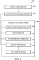
- autopilot recoupling system 100 includes an autopilot recoupling input 102 that is operable to generate an autopilot recoupling signal responsive to a single actuation of autopilot recoupling input 102 by the pilot.
- autopilot recoupling input 102 may be located on instrument panel 40 in the form of a button, hard switch, soft switch or other suitable input means.
- autopilot recoupling input 102 is located on collective pitch control lever 16 such that the pilot does not have to release collective pitch control lever 16 to actuate autopilot recoupling input 102.
- autopilot recoupling input 102 is an existing control on collective pitch control lever 16 known as the go-around input.
- autopilot recoupling input 102 is specifically used during manual flight mode to automatically increase the level of augmentation to the coupled state.
- Autopilot recoupling system 100 also includes an autopilot recoupling signal processor 104 that may be independent of or a part of the flight control computer of the rotorcraft.
- Autopilot recoupling signal processor 104 is designed to execute instructions in order to receive the autopilot recoupling signal generated by autopilot recoupling input 102 and, responsive thereto, determine the states of other systems and generate commands to automatically change the states of other systems as required.
- autopilot recoupling signal processor 104 may be a general purpose processor, a processor core, a multiprocessor, a reconfigurable processor, a microcontroller, a digital signal processor (DSP), an application specific integrated circuit (ASIC), a controller, a state machine, gated logic, discrete hardware components, any other processing unit, or any combination or multiplicity thereof.
- the operations of autopilot recoupling signal processor 104 may take place in a single processing unit, multiple processing units, a single processing core, multiple processing cores, special purpose processing cores, co-processors or any combination thereof.
- autopilot recoupling signal processor 104 may be a software based or hardware based virtualized computing machine executing within one or more other computing machines such as the flight control computer of the rotorcraft.
- Autopilot recoupling system 100 further includes an automatic flight control system 106 that has multiple layers of flight augmentation.
- automatic flight control system 106 include a stability augmentation systems (SAS) layer 108 that provides short-term attitude and attitude rate stabilization typically used during manual flight, a trim systems layer 110 that provides for a neutral spring position of the cyclic pitch control stick, an attitude retention systems (ATT) layer 112 that maintains the pitch and roll attitude of the rotorcraft in a fixed position against transient short-term disturbances and a autopilot systems (AP) layer 114 that provide control over the rotorcraft's flight path, including heading, altitude, vertical speed, navigation tracking, approach and the like.
- autopilot systems layer 114 provides pitch, roll and yaw axis stabilization relative to the desired attitude and heading reference.
- autopilot systems layer 114 is coupled flight director systems (FD) 116 that provide lateral and vertical steering commands to maintain the rotorcraft along a desired lateral and vertical flight path.
- FD flight director systems
- autopilot recoupling signal processor 104 is in communication with stability augmentation systems layer 108, trim systems layer 110, attitude retention systems layer 112 and autopilot systems layer 114. In this manner, when autopilot recoupling signal processor 104 receives the autopilot recoupling signal generated by autopilot recoupling input 102, autopilot recoupling signal processor 104 is operable to determine the state of each of stability augmentation systems layer 108, trim systems layer 110, attitude retention systems layer 112 and autopilot systems layer 114.
- autopilot recoupling signal processor 104 is operable send signals to each of stability augmentation systems layer 108, trim systems layer 110, attitude retention systems layer 112 and autopilot systems layer 114, as required, to achieve the desired recoupling of autopilot systems layer 114 thereby automatically increasing the level of augmentation from the manual flight mode to the coupled flight mode.
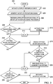
- an algorithm for autopilot recoupling will now be discussed with reference to a logic diagram that is generally designated 200. The process starts with the pilot of the rotorcraft actuating the autopilot recoupling input at operation 202. This results in the generation of the autopilot recoupling signal at operation 204.
- the autopilot recoupling signal is received by the autopilot recoupling signal processor in block 206.
- the autopilot recoupling signal processor determines the state of the trim systems layer in decision 208. If the trim systems layer is not active, the autopilot recoupling signal processor sends commands to activate the trim systems layer in block 210. While the trim systems layer is activating, the autopilot recoupling signal processor waits at delay block 212. Once the trim systems layer is activating or if it was determined at decision 208 that the trim systems layer was already activated, the autopilot recoupling signal processor determines the state of the attitude retention systems layer in decision 214. If the attitude retention systems layer is not engaged, the autopilot recoupling signal processor sends commands to engage the attitude retention systems layer in block 216.
- the autopilot recoupling signal processor now determines the state of the stability augmentation systems layer in decision 218. If the stability augmentation systems layer is engaged, the autopilot recoupling signal processor sends commands to disengage the stability augmentation systems layer in block 220. While the attitude retention systems layer is engaging and the stability augmentation systems layer is disengaging, the autopilot recoupling signal processor waits at delay block 22. Once the attitude retention systems layer is engaged and the stability augmentation systems layer is disengaged or if it was determined at decision 214 that the attitude retention systems layer was already engaged, the autopilot recoupling signal processor determines the state of the autopilot system layer in decision 224.
- the autopilot recoupling signal processor sends commands to recouple the autopilot system layer in block 226.
- a single actuation of the autopilot recoupling input by the pilot during an emergency situation while operating in a manual flight mode results in execution of the multiple actions, in the proper sequence and with the proper timing delays, by the autopilot recoupling signal processor that are required to increase the level of flight augmentation to the desired coupled state.
- This automatic emergency recoupling of the autopilot systems layer alleviates the requirement for the pilot to perform these multiple actions with the proper sequencing and timing delays, which could be difficult for the pilot to perform in certain situations. Accordingly, the autopilot recoupling system of the present disclosure provides important safety enhancements for rotorcraft operations.
- Embodiments of autopilot recoupling system disclosed herein may comprise a computer program that embodies the functions described and illustrated herein, wherein the computer program is implemented in a computer system, such as the autopilot recoupling signal processor disclosed herein that comprises instructions stored in a machine-readable medium and a processor that executes the instructions.
- the computer program is implemented in a computer system, such as the autopilot recoupling signal processor disclosed herein that comprises instructions stored in a machine-readable medium and a processor that executes the instructions.
- the embodiments should not be construed as limited to any one set of computer program instructions.
- a skilled programmer would be able to write such a computer program to implement the disclosed embodiments based on the appended flow charts, algorithms and associated description herein.
- the example embodiments described herein may be used with computer hardware and software that perform the methods and processing functions described previously.
- the systems, methods and procedures described herein may be embodied in a programmable computer, computer-executable software or digital circuitry.
- the software may be stored on computer-readable media such as one or more of a floppy disk, RAM, ROM, hard disk, removable media, flash memory, memory stick, optical media, magnetooptical media, CD-ROM and the like.
- Digital circuitry may include integrated circuits, gate arrays, building block logic, field programmable gate arrays (FPGA) and the like.
- the term "hardware" may include a combination of discrete components, an integrated circuit, an application-specific integrated circuit, a field programmable gate array or other suitable hardware.
- the term "software” may include one or more objects, agents, threads, lines of code, subroutines, separate software applications, two or more lines of code or other suitable software structures operating in one or more software applications, on one or more processors, wherein a processor may include one or more microcomputers or other suitable data processing units, memory devices, input-output devices, displays, data input devices, peripherals, associated drivers, control cards, power sources, network devices or other suitable devices operating under control of software systems in conjunction with the processor or other devices.
- a software system is a system that operates on a processor to perform predetermined functions in response to predetermined data fields.
- any suitable algorithm that would be known to one of skill in the art for performing the function using the associated data fields is contemplated as falling within the scope of the disclosure.
- One of ordinary skill in the art would be able to provide the specific coding for a specific application based on the foregoing disclosure, which is intended to set forth exemplary embodiments of the present disclosure, and not to provide a tutorial for someone having less than ordinary skill in the art, such as someone who is unfamiliar with programming or processors in a suitable programming language.
- a specific algorithm for performing a function can be provided in a flow chart form or in other suitable formats, where the data fields and associated functions can be set forth in an exemplary order of operations, where the order can be rearranged as suitable and is not intended to be limiting unless explicitly stated to be limiting.
Landscapes
- Engineering & Computer Science (AREA)
- Aviation & Aerospace Engineering (AREA)
- Radar, Positioning & Navigation (AREA)
- Remote Sensing (AREA)
- Physics & Mathematics (AREA)
- General Physics & Mathematics (AREA)
- Automation & Control Theory (AREA)
- Mechanical Engineering (AREA)
- Control Of Position, Course, Altitude, Or Attitude Of Moving Bodies (AREA)
Claims (9)
- Autopilot-Wiederankopplungssystem (100) für einen Drehflügler (10), wobei der Drehflügler (10) ein automatisches Flugsteuersystem (106) mit mehreren Ebenen von Flugassistenz (Flight Augmentation), einem manuellen Flugmodus und einem gekoppelten Flugmodus aufweist, wobei das Autopilot-Wiederankopplungssystem (100) umfasst:einen Durchstarteingang (102) auf einem kollektiven Blattverstellungssteuerhebel (16), der gestaltet ist, ein Durchstartmanöver einzuleiten, um einen Landeanflug zu unterbrechen, und ein Autopilot-Wiederankopplungssignal in Antwort auf eine einzelne Betätigung im manuellen Flugmodus zu erzeugen;wobei das Autopilot-Wiederankopplungssystem (100) gekennzeichnet ist durch einen Autopilot-Wiederankopplungssignalprozessor (104), der kommunikationsfähig an den Durchstarteingang (102) gekoppelt ist, wobei der Autopilot-Wiederankopplungssignalprozessor (104) gestaltet ist zum:Empfangen des Autopilot-Wiederankopplungssignals von dem Durchstarteingang (102) und in Antwort auf dieses;Bestimmen eines Zustands des automatischen Flugsteuersystems (106);Aktivieren einer Trimmsystemebene (110) des automatischen Flugsteuersystems (106), wenn die Trimmsystemebene (110) nicht aktiv ist, wobei die Trimmsystemebene (110) zur zyklischen Blattverstellungssteuerung dient;Einrasten einer Lagebeibehaltungssystemebene (112) des automatischen Flugsteuersystems (106), wenn die Lagebeibehaltungssystemebene (112) gelöst ist; undWiederankoppeln einer Autopilotsystemebene (114) des automatischen Flugsteuersystems (106), wodurch der Assistenzgrad von dem manuellen Flugmodus automatisch auf den gekoppelten Flugmodus erhöht wird.
- Verfahren zur Autopilot-Wiederankopplung für einen Drehflügler (10), wobei der Drehflügler (10) ein automatisches Flugsteuersystem (106) mit mehreren Ebenen von Flugassistenz, einem manuellen Flugmodus und einem gekoppelten Flugmodus aufweist, wobei der Drehflügler (10) einen kollektiven Blattverstellungssteuerhebel (16) mit einem Durchstarteingang (102) beinhaltet, der ein Durchstartmanöver einleitet, um einen Landeanflug zu unterbrechen, das Verfahren umfassend:Erzeugen eines Autopilot-Wiederankopplungssignals in Antwort auf eine einzelne Betätigung des Durchstarteingangs (102) im manuellen Flugmodus;wobei das Verfahren gekennzeichnet ist durchEmpfangen des Autopilot-Wiederankopplungssignals bei einem Autopilot-Wiederankopplungssignalprozessor (104) und in Antwort darauf;Bestimmen eines Zustands des automatischen Flugsteuersystems (106);Aktivieren einer Trimmsystemebene (110) des automatischen Flugsteuersystems (106), wenn die Trimmsystemebene (110) nicht aktiv ist, wobei die Trimmsystemebene (110) zur zyklischen Blattverstellungssteuerung dient;Einrasten einer Lagebeibehaltungssystemebene (112) des automatischen Flugsteuersystems (106), wenn die Lagebeibehaltungssystemebene (112) gelöst ist; undWiederankoppeln einer Autopilotsystemebene (114) des automatischen Flugsteuersystems (106), wodurch der Assistenzgrad von dem manuellen Flugmodus automatisch auf den gekoppelten Flugmodus erhöht wird.
- Autopilot-Wiederankopplungssystem (100) nach Anspruch 1, wobei der Autopilot-Wiederankopplungssignalprozessor (104) weiter gestaltet ist, Einrasten der Lagebeibehaltungssystemebene (112) des automatischen Flugsteuersystems (106) zu verzögern, bis die Trimmsystemebene (110) des automatischen Flugsteuersystems (106) aktiv ist.
- Autopilot-Wiederankopplungssystem (100) nach Anspruch 1 oder Anspruch 3, wobei der Autopilot-Wiederankopplungssignalprozessor (104) weiter gestaltet ist, Wiederankopplung der Autopilotsystemebene (114) des automatischen Flugsteuersystems (106) zu verzögern, bis die Lagebeibehaltungssystemebene (112) des automatischen Flugsteuersystems (106) eingerastet ist.
- Autopilot-Wiederankopplungssystem (100) nach Anspruch 1 oder einem der Ansprüche 3 bis 4, wobei der Autopilot-Wiederankopplungssignalprozessor (104) weiter gestaltet ist, die Ebenen des automatischen Flugsteuersystems (106) zu sequenzieren durch:erstens Aktivieren der Trimmsystemebene (110) des automatischen Flugsteuersystems (106), wenn die Trimmsystemebene (110) nicht aktiv ist;zweitens Einrasten der Lagebeibehaltungssystemebene (112) des automatischen Flugsteuersystems (106), wenn die Lagebeibehaltungssystemebene (112) gelöst ist; unddrittens Wiederankoppeln der Autopilotsystemebene (114) des automatischen Flugsteuersystems (106).
- Verfahren nach Anspruch 2, weiter umfassend Verzögern eines Einrastens der Lagebeibehaltungssystemebene (112) des automatischen Flugsteuersystems (106) bis die Trimmsystemebene (110) des automatischen Flugsteuersystems (106) aktiv ist.
- Verfahren nach Anspruch 2 oder Anspruch 6, weiter umfassend Verzögern einer Wiederankopplung der Autopilotsystemebene (114) des automatischen Flugsteuersystems (106), bis die Lagebeibehaltungssystemebene (112) des automatischen Flugsteuersystems (106) eingerastet ist.
- Verfahren nach einem der Ansprüche 2, 6 oder 7, weiter umfassend Sequenzieren der Ebenen des automatischen Flugsteuersystems (106) durch:erstens Aktivieren der Trimmsystemebene (110) des automatischen Flugsteuersystems (106), wenn die Trimmsystemebene (110) nicht aktiv ist;zweitens Einrasten der Lagebeibehaltungssystemebene (112) des automatischen Flugsteuersystems (106), wenn die Lagebeibehaltungssystemebene (112) gelöst ist; unddrittens Wiederankoppeln der Autopilotsystemebene (114) des automatischen Flugsteuersystems (106).
- Drehflügler (10), der einen manuellen Flugmodus und einen gekoppelten Flugmodus aufweist, wobei der Drehflügler (10) umfasst:ein automatisches Flugsteuersystem (106) mit mehreren Ebenen von Flugassistenz;einen kollektiven Blattverstellungssteuerhebel (16); und das Autopilot-Wiederankopplungssystem (100) nach Anspruch 1.
Applications Claiming Priority (1)
| Application Number | Priority Date | Filing Date | Title |
|---|---|---|---|
| US15/894,876 US10816971B2 (en) | 2018-02-12 | 2018-02-12 | Autopilot recoupling for rotorcraft |
Publications (2)
| Publication Number | Publication Date |
|---|---|
| EP3525058A1 EP3525058A1 (de) | 2019-08-14 |
| EP3525058B1 true EP3525058B1 (de) | 2021-08-25 |
Family
ID=65138804
Family Applications (1)
| Application Number | Title | Priority Date | Filing Date |
|---|---|---|---|
| EP19150119.6A Active EP3525058B1 (de) | 2018-02-12 | 2019-01-02 | Autopilot-wiederankopplung für drehflügler |
Country Status (3)
| Country | Link |
|---|---|
| US (2) | US10816971B2 (de) |
| EP (1) | EP3525058B1 (de) |
| CA (1) | CA3030266C (de) |
Families Citing this family (1)
| Publication number | Priority date | Publication date | Assignee | Title |
|---|---|---|---|---|
| US11001376B2 (en) * | 2018-08-07 | 2021-05-11 | Sikorsky Aircraft Corporation | Precision pointing mode of an aircraft |
Family Cites Families (14)
| Publication number | Priority date | Publication date | Assignee | Title |
|---|---|---|---|---|
| US3801049A (en) | 1972-01-31 | 1974-04-02 | Boeing Co | Automatic approach landing and go-around pitch axis control system for aircraft |
| US3848833A (en) * | 1972-07-14 | 1974-11-19 | Sperry Rand Corp | Aircraft automatic flight control system |
| US4382283A (en) * | 1980-08-08 | 1983-05-03 | United Technologies Corporation | Helicopter attitude and airspeed acquisition and retention system |
| US4376979A (en) * | 1980-10-10 | 1983-03-15 | United Technologies Corporation | Updated lock-positioning of foldable helicopter blades |
| US4500967A (en) | 1981-11-27 | 1985-02-19 | United Technologies Corporation | Aircraft short-term roll attitude retention system |
| US4603389A (en) * | 1983-02-16 | 1986-07-29 | Sperry Corporation | Three cue flight director system for helicopters |
| US4577275A (en) * | 1983-05-31 | 1986-03-18 | United Technologies Corporation | Flight director go-around mode |
| US5195039A (en) * | 1990-05-03 | 1993-03-16 | United Technologies Corporation | Hover position hold system for rotary winged aircraft |
| US5714948A (en) * | 1993-05-14 | 1998-02-03 | Worldwide Notifications Systems, Inc. | Satellite based aircraft traffic control system |
| US6460810B2 (en) | 1996-09-06 | 2002-10-08 | Terry Jack James | Semiautonomous flight director |
| FR2900385B1 (fr) * | 2006-04-28 | 2008-12-26 | Eurocopter France | Procede et dispositif d'aide au pilotage d'un giravion au decollage. |
| US8271151B2 (en) * | 2008-03-31 | 2012-09-18 | Sikorsky Aircraft Corporation | Flight control system for rotary wing aircraft |
| US9132913B1 (en) * | 2013-09-26 | 2015-09-15 | Rockwell Collins, Inc. | Simplified auto-flight system coupled with a touchscreen flight control panel |
| RU2623792C2 (ru) * | 2012-02-10 | 2017-06-29 | Мерлин Технолоджи, Инк. | Система и способы управления с помощью автопилота |
-
2018
- 2018-02-12 US US15/894,876 patent/US10816971B2/en active Active
-
2019
- 2019-01-02 EP EP19150119.6A patent/EP3525058B1/de active Active
- 2019-01-15 CA CA3030266A patent/CA3030266C/en active Active
-
2020
- 2020-10-08 US US17/065,872 patent/US11487285B2/en active Active
Non-Patent Citations (1)
| Title |
|---|
| PHILIP ANDREW CROUCHER: "Professional Helicopter Pilot Studies", 31 January 2007 (2007-01-31), XP055688750, ISBN: 978-0-9780269-0-5, Retrieved from the Internet <URL:https://books.google.de/books?id=AovdKRWSqJAC&pg=SA1-PA45&hl=de&source=gbs_selected_pages&cad=2#v=onepage&q&f=false> [retrieved on 20200423] * |
Also Published As
| Publication number | Publication date |
|---|---|
| US20210026352A1 (en) | 2021-01-28 |
| US11487285B2 (en) | 2022-11-01 |
| US10816971B2 (en) | 2020-10-27 |
| CA3030266C (en) | 2021-11-16 |
| EP3525058A1 (de) | 2019-08-14 |
| US20190250606A1 (en) | 2019-08-15 |
| CA3030266A1 (en) | 2019-08-12 |
Similar Documents
| Publication | Publication Date | Title |
|---|---|---|
| EP2620362B1 (de) | Flugsteuerungssystemmodus und Verfahren zur Bereitstellung von Flugzeuggeschwindigkeitssteuerung durch Verwendung von aktueller Ein-Aus-Steuerung | |
| EP3379365B1 (de) | System und verfahren zur drehflüglerkurssteuerung | |
| US6460810B2 (en) | Semiautonomous flight director | |
| EP3357809B1 (de) | Systeme und verfahren zur stabilisierung von längsbeschleunigung eines drehflüglers | |
| CN110498054B (zh) | 用于使用可变摩擦和力梯度进行触觉提示的系统和方法 | |
| US20130060406A1 (en) | Flight Control Laws for Vertical Flight Path | |
| EP3366574B1 (de) | Umgekehrter taktiler hinweis zum überdrehzahlschutz für drehflüglerrotor | |
| EP2812763B1 (de) | Autopilotsteueranordnung und verfahren | |
| EP3560824B1 (de) | System und verfahren für automatischen heckschlagschutz eines drehflügelflugzeuges | |
| EP3620373A1 (de) | Stuck-in-detent-monitore für kollektive und zyklische sticks | |
| US9944384B2 (en) | Method and a device for controlling at least two subsystems of an aircraft | |
| US11447272B2 (en) | Interactive electronic checklists for autonomous aircraft | |
| US11312480B2 (en) | System and method for controlling rotorcraft | |
| EP3599160B1 (de) | System und verfahren zur flugsteuerung eines drehflüglers | |
| CN109515708B (zh) | 用于尾旋翼裕度识别的系统和方法 | |
| EP3569497B1 (de) | System und verfahren zur taktilen signalisierung durch drehflügler-pilotensteuerungen mit einem variablen reibungs- und kraftgradienten | |
| EP3677505B1 (de) | System und verfahren zur steuerung eines drehflüglers | |
| EP3492373B1 (de) | System und verfahren zur flugmodusanzeige | |
| EP3627271B1 (de) | System und verfahren zur steuerung eines drehflüglers | |
| US11487285B2 (en) | Autopilot recoupling for rotorcraft | |
| CN111392036A (zh) | 用于控制旋翼飞行器的系统及方法 |
Legal Events
| Date | Code | Title | Description |
|---|---|---|---|
| STAA | Information on the status of an ep patent application or granted ep patent |
Free format text: STATUS: EXAMINATION IS IN PROGRESS |
|
| PUAI | Public reference made under article 153(3) epc to a published international application that has entered the european phase |
Free format text: ORIGINAL CODE: 0009012 |
|
| 17P | Request for examination filed |
Effective date: 20190102 |
|
| AK | Designated contracting states |
Kind code of ref document: A1 Designated state(s): AL AT BE BG CH CY CZ DE DK EE ES FI FR GB GR HR HU IE IS IT LI LT LU LV MC MK MT NL NO PL PT RO RS SE SI SK SM TR |
|
| AX | Request for extension of the european patent |
Extension state: BA ME |
|
| GRAP | Despatch of communication of intention to grant a patent |
Free format text: ORIGINAL CODE: EPIDOSNIGR1 |
|
| STAA | Information on the status of an ep patent application or granted ep patent |
Free format text: STATUS: GRANT OF PATENT IS INTENDED |
|
| INTG | Intention to grant announced |
Effective date: 20201130 |
|
| GRAJ | Information related to disapproval of communication of intention to grant by the applicant or resumption of examination proceedings by the epo deleted |
Free format text: ORIGINAL CODE: EPIDOSDIGR1 |
|
| RAP1 | Party data changed (applicant data changed or rights of an application transferred) |
Owner name: TEXTRON INNOVATIONS INC. |
|
| STAA | Information on the status of an ep patent application or granted ep patent |
Free format text: STATUS: EXAMINATION IS IN PROGRESS |
|
| GRAP | Despatch of communication of intention to grant a patent |
Free format text: ORIGINAL CODE: EPIDOSNIGR1 |
|
| STAA | Information on the status of an ep patent application or granted ep patent |
Free format text: STATUS: GRANT OF PATENT IS INTENDED |
|
| INTC | Intention to grant announced (deleted) | ||
| INTG | Intention to grant announced |
Effective date: 20210203 |
|
| GRAJ | Information related to disapproval of communication of intention to grant by the applicant or resumption of examination proceedings by the epo deleted |
Free format text: ORIGINAL CODE: EPIDOSDIGR1 |
|
| STAA | Information on the status of an ep patent application or granted ep patent |
Free format text: STATUS: EXAMINATION IS IN PROGRESS |
|
| GRAP | Despatch of communication of intention to grant a patent |
Free format text: ORIGINAL CODE: EPIDOSNIGR1 |
|
| STAA | Information on the status of an ep patent application or granted ep patent |
Free format text: STATUS: GRANT OF PATENT IS INTENDED |
|
| GRAS | Grant fee paid |
Free format text: ORIGINAL CODE: EPIDOSNIGR3 |
|
| INTC | Intention to grant announced (deleted) | ||
| GRAA | (expected) grant |
Free format text: ORIGINAL CODE: 0009210 |
|
| STAA | Information on the status of an ep patent application or granted ep patent |
Free format text: STATUS: THE PATENT HAS BEEN GRANTED |
|
| INTG | Intention to grant announced |
Effective date: 20210701 |
|
| AK | Designated contracting states |
Kind code of ref document: B1 Designated state(s): AL AT BE BG CH CY CZ DE DK EE ES FI FR GB GR HR HU IE IS IT LI LT LU LV MC MK MT NL NO PL PT RO RS SE SI SK SM TR |
|
| REG | Reference to a national code |
Ref country code: CH Ref legal event code: EP |
|
| REG | Reference to a national code |
Ref country code: DE Ref legal event code: R096 Ref document number: 602019007026 Country of ref document: DE |
|
| REG | Reference to a national code |
Ref country code: IE Ref legal event code: FG4D Ref country code: AT Ref legal event code: REF Ref document number: 1424452 Country of ref document: AT Kind code of ref document: T Effective date: 20210915 |
|
| REG | Reference to a national code |
Ref country code: LT Ref legal event code: MG9D |
|
| REG | Reference to a national code |
Ref country code: NL Ref legal event code: MP Effective date: 20210825 |
|
| REG | Reference to a national code |
Ref country code: AT Ref legal event code: MK05 Ref document number: 1424452 Country of ref document: AT Kind code of ref document: T Effective date: 20210825 |
|
| PG25 | Lapsed in a contracting state [announced via postgrant information from national office to epo] |
Ref country code: RS Free format text: LAPSE BECAUSE OF FAILURE TO SUBMIT A TRANSLATION OF THE DESCRIPTION OR TO PAY THE FEE WITHIN THE PRESCRIBED TIME-LIMIT Effective date: 20210825 Ref country code: SE Free format text: LAPSE BECAUSE OF FAILURE TO SUBMIT A TRANSLATION OF THE DESCRIPTION OR TO PAY THE FEE WITHIN THE PRESCRIBED TIME-LIMIT Effective date: 20210825 Ref country code: ES Free format text: LAPSE BECAUSE OF FAILURE TO SUBMIT A TRANSLATION OF THE DESCRIPTION OR TO PAY THE FEE WITHIN THE PRESCRIBED TIME-LIMIT Effective date: 20210825 Ref country code: FI Free format text: LAPSE BECAUSE OF FAILURE TO SUBMIT A TRANSLATION OF THE DESCRIPTION OR TO PAY THE FEE WITHIN THE PRESCRIBED TIME-LIMIT Effective date: 20210825 Ref country code: HR Free format text: LAPSE BECAUSE OF FAILURE TO SUBMIT A TRANSLATION OF THE DESCRIPTION OR TO PAY THE FEE WITHIN THE PRESCRIBED TIME-LIMIT Effective date: 20210825 Ref country code: PT Free format text: LAPSE BECAUSE OF FAILURE TO SUBMIT A TRANSLATION OF THE DESCRIPTION OR TO PAY THE FEE WITHIN THE PRESCRIBED TIME-LIMIT Effective date: 20211227 Ref country code: NO Free format text: LAPSE BECAUSE OF FAILURE TO SUBMIT A TRANSLATION OF THE DESCRIPTION OR TO PAY THE FEE WITHIN THE PRESCRIBED TIME-LIMIT Effective date: 20211125 Ref country code: AT Free format text: LAPSE BECAUSE OF FAILURE TO SUBMIT A TRANSLATION OF THE DESCRIPTION OR TO PAY THE FEE WITHIN THE PRESCRIBED TIME-LIMIT Effective date: 20210825 Ref country code: BG Free format text: LAPSE BECAUSE OF FAILURE TO SUBMIT A TRANSLATION OF THE DESCRIPTION OR TO PAY THE FEE WITHIN THE PRESCRIBED TIME-LIMIT Effective date: 20211125 Ref country code: LT Free format text: LAPSE BECAUSE OF FAILURE TO SUBMIT A TRANSLATION OF THE DESCRIPTION OR TO PAY THE FEE WITHIN THE PRESCRIBED TIME-LIMIT Effective date: 20210825 |
|
| PG25 | Lapsed in a contracting state [announced via postgrant information from national office to epo] |
Ref country code: PL Free format text: LAPSE BECAUSE OF FAILURE TO SUBMIT A TRANSLATION OF THE DESCRIPTION OR TO PAY THE FEE WITHIN THE PRESCRIBED TIME-LIMIT Effective date: 20210825 Ref country code: LV Free format text: LAPSE BECAUSE OF FAILURE TO SUBMIT A TRANSLATION OF THE DESCRIPTION OR TO PAY THE FEE WITHIN THE PRESCRIBED TIME-LIMIT Effective date: 20210825 Ref country code: GR Free format text: LAPSE BECAUSE OF FAILURE TO SUBMIT A TRANSLATION OF THE DESCRIPTION OR TO PAY THE FEE WITHIN THE PRESCRIBED TIME-LIMIT Effective date: 20211126 |
|
| PG25 | Lapsed in a contracting state [announced via postgrant information from national office to epo] |
Ref country code: NL Free format text: LAPSE BECAUSE OF FAILURE TO SUBMIT A TRANSLATION OF THE DESCRIPTION OR TO PAY THE FEE WITHIN THE PRESCRIBED TIME-LIMIT Effective date: 20210825 |
|
| PG25 | Lapsed in a contracting state [announced via postgrant information from national office to epo] |
Ref country code: DK Free format text: LAPSE BECAUSE OF FAILURE TO SUBMIT A TRANSLATION OF THE DESCRIPTION OR TO PAY THE FEE WITHIN THE PRESCRIBED TIME-LIMIT Effective date: 20210825 |
|
| REG | Reference to a national code |
Ref country code: DE Ref legal event code: R097 Ref document number: 602019007026 Country of ref document: DE |
|
| PG25 | Lapsed in a contracting state [announced via postgrant information from national office to epo] |
Ref country code: SM Free format text: LAPSE BECAUSE OF FAILURE TO SUBMIT A TRANSLATION OF THE DESCRIPTION OR TO PAY THE FEE WITHIN THE PRESCRIBED TIME-LIMIT Effective date: 20210825 Ref country code: SK Free format text: LAPSE BECAUSE OF FAILURE TO SUBMIT A TRANSLATION OF THE DESCRIPTION OR TO PAY THE FEE WITHIN THE PRESCRIBED TIME-LIMIT Effective date: 20210825 Ref country code: RO Free format text: LAPSE BECAUSE OF FAILURE TO SUBMIT A TRANSLATION OF THE DESCRIPTION OR TO PAY THE FEE WITHIN THE PRESCRIBED TIME-LIMIT Effective date: 20210825 Ref country code: EE Free format text: LAPSE BECAUSE OF FAILURE TO SUBMIT A TRANSLATION OF THE DESCRIPTION OR TO PAY THE FEE WITHIN THE PRESCRIBED TIME-LIMIT Effective date: 20210825 Ref country code: CZ Free format text: LAPSE BECAUSE OF FAILURE TO SUBMIT A TRANSLATION OF THE DESCRIPTION OR TO PAY THE FEE WITHIN THE PRESCRIBED TIME-LIMIT Effective date: 20210825 Ref country code: AL Free format text: LAPSE BECAUSE OF FAILURE TO SUBMIT A TRANSLATION OF THE DESCRIPTION OR TO PAY THE FEE WITHIN THE PRESCRIBED TIME-LIMIT Effective date: 20210825 |
|
| PLBE | No opposition filed within time limit |
Free format text: ORIGINAL CODE: 0009261 |
|
| STAA | Information on the status of an ep patent application or granted ep patent |
Free format text: STATUS: NO OPPOSITION FILED WITHIN TIME LIMIT |
|
| 26N | No opposition filed |
Effective date: 20220527 |
|
| PG25 | Lapsed in a contracting state [announced via postgrant information from national office to epo] |
Ref country code: SI Free format text: LAPSE BECAUSE OF FAILURE TO SUBMIT A TRANSLATION OF THE DESCRIPTION OR TO PAY THE FEE WITHIN THE PRESCRIBED TIME-LIMIT Effective date: 20210825 Ref country code: MC Free format text: LAPSE BECAUSE OF FAILURE TO SUBMIT A TRANSLATION OF THE DESCRIPTION OR TO PAY THE FEE WITHIN THE PRESCRIBED TIME-LIMIT Effective date: 20210825 |
|
| REG | Reference to a national code |
Ref country code: CH Ref legal event code: PL |
|
| REG | Reference to a national code |
Ref country code: BE Ref legal event code: MM Effective date: 20220131 |
|
| PG25 | Lapsed in a contracting state [announced via postgrant information from national office to epo] |
Ref country code: LU Free format text: LAPSE BECAUSE OF NON-PAYMENT OF DUE FEES Effective date: 20220102 |
|
| PG25 | Lapsed in a contracting state [announced via postgrant information from national office to epo] |
Ref country code: BE Free format text: LAPSE BECAUSE OF NON-PAYMENT OF DUE FEES Effective date: 20220131 |
|
| PG25 | Lapsed in a contracting state [announced via postgrant information from national office to epo] |
Ref country code: LI Free format text: LAPSE BECAUSE OF NON-PAYMENT OF DUE FEES Effective date: 20220131 Ref country code: CH Free format text: LAPSE BECAUSE OF NON-PAYMENT OF DUE FEES Effective date: 20220131 |
|
| PG25 | Lapsed in a contracting state [announced via postgrant information from national office to epo] |
Ref country code: IE Free format text: LAPSE BECAUSE OF NON-PAYMENT OF DUE FEES Effective date: 20220102 |
|
| P01 | Opt-out of the competence of the unified patent court (upc) registered |
Effective date: 20230602 |
|
| REG | Reference to a national code |
Ref country code: DE Ref legal event code: R079 Ref document number: 602019007026 Country of ref document: DE Free format text: PREVIOUS MAIN CLASS: G05D0001080000 Ipc: G05D0001490000 |
|
| PG25 | Lapsed in a contracting state [announced via postgrant information from national office to epo] |
Ref country code: MK Free format text: LAPSE BECAUSE OF FAILURE TO SUBMIT A TRANSLATION OF THE DESCRIPTION OR TO PAY THE FEE WITHIN THE PRESCRIBED TIME-LIMIT Effective date: 20210825 Ref country code: CY Free format text: LAPSE BECAUSE OF FAILURE TO SUBMIT A TRANSLATION OF THE DESCRIPTION OR TO PAY THE FEE WITHIN THE PRESCRIBED TIME-LIMIT Effective date: 20210825 |
|
| PG25 | Lapsed in a contracting state [announced via postgrant information from national office to epo] |
Ref country code: HU Free format text: LAPSE BECAUSE OF FAILURE TO SUBMIT A TRANSLATION OF THE DESCRIPTION OR TO PAY THE FEE WITHIN THE PRESCRIBED TIME-LIMIT; INVALID AB INITIO Effective date: 20190102 |
|
| PG25 | Lapsed in a contracting state [announced via postgrant information from national office to epo] |
Ref country code: MT Free format text: LAPSE BECAUSE OF FAILURE TO SUBMIT A TRANSLATION OF THE DESCRIPTION OR TO PAY THE FEE WITHIN THE PRESCRIBED TIME-LIMIT Effective date: 20210825 |
|
| PG25 | Lapsed in a contracting state [announced via postgrant information from national office to epo] |
Ref country code: TR Free format text: LAPSE BECAUSE OF FAILURE TO SUBMIT A TRANSLATION OF THE DESCRIPTION OR TO PAY THE FEE WITHIN THE PRESCRIBED TIME-LIMIT Effective date: 20210825 |
|
| PGFP | Annual fee paid to national office [announced via postgrant information from national office to epo] |
Ref country code: GB Payment date: 20260127 Year of fee payment: 8 |
|
| PGFP | Annual fee paid to national office [announced via postgrant information from national office to epo] |
Ref country code: DE Payment date: 20260128 Year of fee payment: 8 |
|
| PGFP | Annual fee paid to national office [announced via postgrant information from national office to epo] |
Ref country code: IT Payment date: 20260121 Year of fee payment: 8 |
|
| PGFP | Annual fee paid to national office [announced via postgrant information from national office to epo] |
Ref country code: FR Payment date: 20260126 Year of fee payment: 8 |