EP3525103A1 - Automatisierungsverwaltungssystem und -verfahren - Google Patents
Automatisierungsverwaltungssystem und -verfahren Download PDFInfo
- Publication number
- EP3525103A1 EP3525103A1 EP19166532.2A EP19166532A EP3525103A1 EP 3525103 A1 EP3525103 A1 EP 3525103A1 EP 19166532 A EP19166532 A EP 19166532A EP 3525103 A1 EP3525103 A1 EP 3525103A1
- Authority
- EP
- European Patent Office
- Prior art keywords
- task
- value
- time
- timing
- generating
- Prior art date
- Legal status (The legal status is an assumption and is not a legal conclusion. Google has not performed a legal analysis and makes no representation as to the accuracy of the status listed.)
- Granted
Links
Images


Classifications
-
- G—PHYSICS
- G05—CONTROLLING; REGULATING
- G05B—CONTROL OR REGULATING SYSTEMS IN GENERAL; FUNCTIONAL ELEMENTS OF SUCH SYSTEMS; MONITORING OR TESTING ARRANGEMENTS FOR SUCH SYSTEMS OR ELEMENTS
- G05B9/00—Safety arrangements
- G05B9/02—Safety arrangements electric
-
- G—PHYSICS
- G05—CONTROLLING; REGULATING
- G05B—CONTROL OR REGULATING SYSTEMS IN GENERAL; FUNCTIONAL ELEMENTS OF SUCH SYSTEMS; MONITORING OR TESTING ARRANGEMENTS FOR SUCH SYSTEMS OR ELEMENTS
- G05B23/00—Testing or monitoring of control systems or parts thereof
- G05B23/02—Electric testing or monitoring
- G05B23/0205—Electric testing or monitoring by means of a monitoring system capable of detecting and responding to faults
- G05B23/0218—Electric testing or monitoring by means of a monitoring system capable of detecting and responding to faults characterised by the fault detection method dealing with either existing or incipient faults
- G05B23/0224—Process history based detection method, e.g. whereby history implies the availability of large amounts of data
- G05B23/0227—Qualitative history assessment, whereby the type of data acted upon, e.g. waveforms, images or patterns, is not relevant, e.g. rule based assessment; if-then decisions
- G05B23/0232—Qualitative history assessment, whereby the type of data acted upon, e.g. waveforms, images or patterns, is not relevant, e.g. rule based assessment; if-then decisions based on qualitative trend analysis, e.g. system evolution
-
- G—PHYSICS
- G06—COMPUTING OR CALCULATING; COUNTING
- G06N—COMPUTING ARRANGEMENTS BASED ON SPECIFIC COMPUTATIONAL MODELS
- G06N5/00—Computing arrangements using knowledge-based models
- G06N5/04—Inference or reasoning models
-
- G—PHYSICS
- G05—CONTROLLING; REGULATING
- G05B—CONTROL OR REGULATING SYSTEMS IN GENERAL; FUNCTIONAL ELEMENTS OF SUCH SYSTEMS; MONITORING OR TESTING ARRANGEMENTS FOR SUCH SYSTEMS OR ELEMENTS
- G05B2219/00—Program-control systems
- G05B2219/20—Pc systems
- G05B2219/24—Pc safety
- G05B2219/24075—Predict control element state changes, event changes
Definitions
- Equipment monitoring systems can collect data from, for example, computational devices (programmable logic controllers, programmable automation controller, etc.) in equipment located throughout the facility. The collected data can assist in, for example, monitoring equipment health, predicting when equipment failure will occur and/or informing operators when equipment failure has occurred.
- a computer interface such as a human-machine interface (HMI) may be interconnected with the computational devices to facilitate programming or control thereof, to monitor the computational device, or to provide other such functionality.
- HMI human-machine interface
- CIP common industrial protocol
- Embodiments of a method for monitoring performance of at least one task in controlled equipment are disclosed herein.
- the method includes collecting a series of signals associated with the at least one task. At least some of the signals in the series define timing values for the at least one task.
- the method also includes comparing each of at least some of the timing values to a reference value and generating an accumulated variance value based on the comparisons. Further, the method includes selectively generating a predictive failure indication based on the generated accumulated variance value.
- the method includes collecting a series of signals associated with the at least one task. At least some of the signals in the series define at least a first timing value for the at least one task. The method also includes comparing the first timing value to a reference value. The reference value is based on data other than the series of signals. Further, the method includes generating an indication based on the comparison.
- Embodiments of an apparatus for monitoring data from a computational device configured to control at least one task in equipment are also disclosed herein.
- the apparatus includes a memory a processor configured to execute instructions stored in the memory to collect a series of signals associated with the at least one task. At least some of the signals in the series define timing values for the at least one task.
- the processor is also configured to execute instructions stored in the memory to compare each of at least some of the timing values to a reference value and generate an accumulated variance value based on the comparisons. Further, the processor is configured to execute instructions stored in the memory to selectively generate a predictive failure indication based on the generated accumulated variance value.
- an automation management system 10 includes a PLC 12 and a PC 14.
- the data that is collected from the PLC 12 can be based on, for example, the programming of the PLC 12, as will be discussed in more detail below.
- PC 14 can include a data access server, such as an OPC (OLE, Object Linking and Embedding, for Process Control) server, to retrieve data from PLC 12 and to convert the hardware communication protocol used by PLC 12 into the server protocol (e.g. OPC protocol).
- OPC OPC
- the data access server is, by way of example, an OPC server other suitable data access servers are available having custom and/or standardized data formats/protocols.
- the data retrieved by the OPC server can optionally be stored in a database (not shown).
- Both PLC 12 and PC 14 can have suitable components such as a processor, memory, input/output modules, and programming instructions loaded thereon as desired or required.
- PLC 12 and PC 14 can be in transmit/receive data through a wired or wireless communication protocol such as RS232, Ethernet, SCADA (Supervisory Control and Data Acquisition). Other suitable communication protocols are available.
- PLC 12 may be in communication with PC 14, or other PCs.
- PLC 12 can be connected to and control any equipment including machines such as clamps or drills. To ease the reader's understanding of the embodiments, the description will refer to machines although the embodiments can be used with equipment other than the machines.
- the machines can be part of any system including but non-limited to machining, packaging, automated assembly or material handling.
- PLC 12 is not limited to being connected to a machine and/or can be connected to any other suitable device.
- Other devices may be used in lieu or in addition to PLC 12 such as PACs (Process Automation Controllers) or DCS (Distributed Control Systems) or any other suitable computational device.
- PACs Process Automation Controllers
- DCS Distributed Control Systems
- the PC 14 can also include a client application to obtain the data from or send commands to PLC 12 through the OPC server.
- the client application can be connected to several OPC servers or two or more OPC servers can be connected to share data.
- PC 14 can include a graphical display representing information such as the status of the machines on the plant floor.
- the HMI can also be located as a separate device from the PC 14.
- PCs Personal Digital Assistants
- PDAs Personal Digital Assistants
- palm top computers palm top computers
- smart phones smart phones
- game consoles any other information processing devices.
- modules e.g. OPC server, client application, etc.
- modules can be distributed across one or more hardware components as desired or required.
- PLC 12 One use of PLC 12 is to take a machine through a repetitive sequence of one or more operations or tasks.
- the completion of the repetitive sequence of tasks can be denoted as a cycle.
- Each task can have, for example, an optimal design start time and design end time in the sequence and resulting duration time ("reference values").
- These optimal design times can be based on, for example, the manufacturer's specification or an equipment user's study of when and how long a certain tasks should be executed.
- the design times can be determined by any other method.
- an exemplary design cycle 30 is illustrated from time t1-t20.
- the design cycle includes nine tasks 32a-i (collectively referred to as tasks 32).
- each task 32 is designed to begin operation at a specific start time and designed to end operation at a specific end time.
- PLC 12 can be programmed to collect this start time and end time information and made available to PC 14.
- the start time and end time information can be sent to PC 14 or PC 14 can periodically poll PLC 12.
- PLC 12 can collect and transmit information that can be used to appropriately monitor and determine a reactive, preventive and/or predictive plan for the machine(s) being controlled.
- advance pin 1 task 32a starts at t0 and ends at t1 and has a duration of t1-t0
- advance pin 2 task 32b starts at t0 and ends at t1 and has a duration of t1-t0
- close clamp 1 task 32c starts at t1 and ends at t2 and has a duration of t2-tl
- close clamp 2 task 32d starts at t1 and ends at t2 and has a duration of t2-t1
- weld task 32e starts at t2 and ends at t18 and has a duration of t18-t2
- open clamp 1 task 32f starts at t18 and ends at t19 and has a duration of t19-t18
- open clamp 2 task 32g starts at t18 and ends at t19 and has a duration of t19-t18
- return pin I task 32h starts at t
- PLC 12 generally receives input data, output data and/or other data ("series of signals") from the machines they control.
- Each task 32 can be defined as a series of one or more input and/or output states.
- the tasks 32 can be defined, for example, by a programmer during software development for the PLC 12.
- PLC 12 can determine whether advance pin 1 task 32a has been complete by examining whether certain inputs and/or outputs or any other condition (e.g. timer) are set to their correct states or values.
- states does not limit embodiments of the invention to digital input and/or signals.
- analog inputs or outputs, or a combination of digital and analog inputs or outputs can be collected from the machines and can be used to define each task 32.
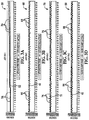
- FIGS. 3A-3D exemplary performance graphs 50, 60, 70 and 80 of task 32a, task 32b, task 32c and tasks 32d are shown, respectively, over one hundred cycles.
- advance pin 1 task 32a is designed to complete its operation within, for example, one second, as indicated by base line 52.
- the actual operation advance pin 1 task 32a is indicated by a series of plot points 54.
- Each plot point 54 can represent the actual completion time or duration ("timing value") for task 32a during that particular cycle.
- the completion time of task 32a is gradually increasing. This can, for example, provide notice to a user that an input and/or an output associated with task 32a is or may in the future experiencing a failure. Accordingly, if desired or required, appropriate maintenance procedures can be undertaken.
- other timing values are available in lieu of or in addition to duration.
- other timing values include a start time or end time for the task.
- advance pin 2 task 32b is designed to complete its operation within one second, as indicated by base line 62 and the actual operation of task 32b is indicated by a series of plot points 64.
- Close clamp 1 task 32c is designed to complete its operation within one second, as indicated by base line 72 and the actual operation of task 32c is indicated by a series of plot points 74.
- Close clamp 2 task 32d is designed to complete its operation within one second, as indicated by base line 82 and the actual operation of task 32d is indicated by a series of plot points 84. Since the series of plots points 64, 74 and 84 do not, for example, consistently deviate from the base lines 62, 72 and 82, the user(s) can, for example, ascertain that the tasks are 32b-d are operating normally.
- performance graphs 50, 60, 70 and 80 are merely exemplary. Other performance graphs may contain other data, depicted using another graph type, or combined into one graph. Further, although 100 cycles are shown, performance graphs can contain any number of cycles.
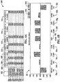
- the performance data diagram 100 includes information for a first cycle 102
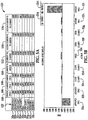
- the performance data diagram 120 includes information for a twentieth cycle 122
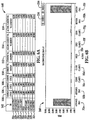
- performance data diagram 140 includes information for a hundredth cycle 142. It is to be understood that these cycles are selected from the 100 cycles previously shown but are in no way intended to limit the scope of the embodiments disclosed herein. Rather, selection of these cycles is intended to assist the reader's understanding of embodiments. Other cycles can contain different data.
- the cycles 102, 122 and 142 can include tasks 32.
- performance data can include design cycle data 104, learned cycle data 106, current cycle data 108 ("timing value"), current versus design cycle data 110, current versus learned cycle data 112, accumulated current versus design cycle data 114 and accumulated current versus learned cycle data 114.
- Design cycle data 104 can include data pertaining to design times for the certain machine performing the tasks and is not based on the series of signals collected from the particular machine being monitored. Thus, as discussed previously, each task may have an expected start time, end time and duration based on for example, a manufacturer's specification or as set by a user. For example, if a manufacturer's specification indicates that the weld task 32e should be performed in 16 seconds, the design cycle time can be 16 seconds. Design cycle times 104 can be determined by other methods. The design cycle times 104 are preferably the same throughout the execution of the tasks 32, although in some embodiments the design cycle can change.
- Learned cycle time 106 can include data pertaining to a reference time for a certain machine.
- learned cycle time 106 is a reference value based on the series of signals collected from the machine.
- a user can cause the machine to execute a cycle of tasks 32a-i, in order to teach the system the reference data for that particular machine.
- These learned cycle times can be recorded, for example, during setup of the machine, maintenance of the machine or at any other suitable time.
- the machine can begin operation and can begin collecting current cycle times for each task 32.
- Current cycle time 108 can be the duration of the time needed to complete each task (i.e. difference between start time and end time). Thus, for example, as shown in FIG.
- the welding process lasted 16.073 seconds.
- the welding process lasted 15.987 seconds.
- the welding process lasted 15.937 seconds.
- the start time and end time and/or the duration for each task 32 can be collected and sent to the PC 14.
- the current versus design time can be calculated for each task 32.
- Current versus design time 110 can be the difference between the design cycle times 104 and the current cycle times 108.
- current versus learned time 112 can be the difference between the learned cycle times 106 and the current cycle times 108.
- the current versus design time 110 and current versus learned time 112 calculations can be made by PC 14 or by any other module. For example, if the HMI is a separate module than the PC 14, the HMI can perform the calculations.
- a threshold value can indicate that the task is operating normally and a normal operation indicator can be generated (e.g. at PC 14) as will be discussed in more detail below.
- a normal operation indicator can be generated (e.g. at PC 14) as will be discussed in more detail below.
- the current versus design time 110 is between 10% and 25% of the design cycle time 104, then the current cycle has been executed within a cautionary threshold.
- the cautionary threshold can indicate that an action may be needed on some input or output associated with that certain task.
- a cautionary indicator can be generated that indicates that the current cycle is within the cautionary threshold. If the current versus design time 110 is greater than 25% of the design cycle time 104, then the current cycle has been executed within a warning threshold.
- the warning threshold can indicate that an action may be needed on some input or output associated with that certain task and a warning indicator can be generated as will be discussed in more detail below.
- any number of threshold ranges can be used with different range values.
- the current versus learned time 112 instead of the current versus design time 110 can be used to determine whether the task 32 is operating within a predetermined threshold. Other embodiments may contain different calculations to ascertain whether the execution time of the tasks is acceptable. For example, rather than using the design cycle time 104, the learned cycle time can be used to ascertain whether the task has been executed within an acceptable threshold.
- this information can be displayed to the user(s). For example, if the tasks 32 have been executed in the acceptable threshold, that particular task can be highlighted, for example, in green ("normal operation indicator”). Similarly, for example, if the tasks 32 have been executed within the cautionary threshold, that particular task can be highlighted in yellow (“cautionary indicator”) and if the tasks 32 have been executed within the warning threshold, that particular task can be highlighted in red (“warning indicator”). In other embodiment, the indicators are audible rather than visually displayed to the user. Other techniques for generating indicators are also available.
- tasks 32a-i have been executed in the acceptable threshold.
- tasks 32a-h have been executed in the acceptable threshold and task 32i has been executed within the cautionary threshold.
- tasks 32b-h have been executed within the acceptable threshold and tasks 32a and 32i have been executed within the warning threshold.
- the accumulated current versus design time 114 (“accumulated variance value") can be calculated for each task 32.
- the accumulated current versus design time 114 can be the running total or the sum of the current versus design time 110 across some or all cycles (e.g. 100 cycles) for a particular machine run. The machine run may be terminated based on, for example, user(s) intervention, machine breakdown etc.
- the accumulated current versus learned time 116 (“accumulated variance value") can be calculated for each task 32.
- the accumulated current versus design time 116 can be the running total or sum of the current versus learned time 116 across all cycles (e.g. 100 cycles) for a particular machine run.
- the accumulated current versus learned time 114 and the accumulated current versus design time 116 can be calculated at PC 14, or on any other computational device (e.g. PLC 12).
- Both the accumulated current versus design times 114 and the accumulated current versus learned times 116 can be graphed on a machine level performance diagram for each cycle and for each task 32 as shown in FIGS. 4B , 5B and 6B .
- Series1 214 represents the accumulated current versus design time 114 for each task 32
- Series2 216 represents the accumulated current versus learned time 116 for each task.
- the machine level performance can be displayed, for example, a HMI.
- the accumulated current versus design time 114 and/or the accumulated current versus learned time 116 increase, it can alert the user(s) that the particular task may be experiencing a problem that may require an action. For example, as can be seen from FIG.
- task 32a has an accumulated current versus design time 114 of 24.356 seconds and an accumulated current versus learned time of 24.656 seconds, which may indicate that advance pin2 task 32a is experiencing a problem.
- a similar observation can be made in regard to return pin2 task 32i.
- FIG. 7 is a prediction routine 300 that can be used in automation management system 10.
- a user enters one or more threshold values for at least one task.
- a user enters one or more reference values (e.g. design cycle time 104) at block 304.
- Control then moves to block 306 to collect data or a series of signals from, for example, a machine being controlled PLC 12.
- PLC 12 can, in turn, send timing values to PC 14 related to the performance of one or more tasks (e.g. tasks 32a-i).
- the series of signals can be collected directly from the machine being controlled.
- control moves to determine the variances or differences (e.g. current versus design time 110) between the reference value and one or more of the timing values collected from PLC 12 over a period of time.
- Design cycle data and/or learned cycle data can be used to determine the differences.
- the period of time may be any suitable value. As one example, the period of time is 2 seconds.
- control moves to sum the variance to generate an accumulated variance value (e.g. accumulated current versus design time 114).
- control moves to block 312 to perform trend pattern detection to predict a potential failure of the machine.
- trend pattern detection determines a slope of the accumulated variance value.
- Control then moves to decision block 314 to determine if a pattern has been detected.
- a pattern can be detected if the slope of the accumulated variance value is either generally increasing or generally decreasing over the period of time rather than being generally constant. When the slope is generally constant, the accumulated variance value does not deviate significantly from zero. In other words, the value of the differences (determined at block 308) are at or close to zero.
- FIG. 3A One example of a detected pattern, is shown in FIG. 3A where the slope of the accumulated variance value is illustrated as generally increasing. In contrast, FIGS. 3B-D show the slopes of their respective accumulated variance values as generally constant. Other suitable techniques of pattern detection are also available that do not include calculation of slope for the accumulated variance value
- control can move to step 316 to report the prediction of the potential failure.
- the prediction can be reported by generating the predictive failure indicator. Otherwise, if no pattern is detected (i.e. the slope is generally constant) the predictive failure indicator is not generated.
- the predictive failure indicator can be audible or visually displayed to the user at PC 14. Other suitable techniques for generating the predictive failure are also available.
- the information collected from PLC 12 can be used in all aspects of reactive, predictive and preventive maintenance.
- the operation of the tasks 32 can be monitored using any other statistical process control method or any other suitable method.
- the information related to the executed tasks can be displayed in any other manner using control charts or any other suitable graphical display such as a Gantt chart.
- embodiments of the present invention are not limited to use in industrial factories, packaging plants etc.
- embodiments of the present invention can be suitably incorporated into a monitoring and maintenance system of a rollercoaster or any other system that contains a computational device.
Landscapes
- Engineering & Computer Science (AREA)
- General Physics & Mathematics (AREA)
- Physics & Mathematics (AREA)
- Automation & Control Theory (AREA)
- Theoretical Computer Science (AREA)
- Artificial Intelligence (AREA)
- Data Mining & Analysis (AREA)
- Evolutionary Computation (AREA)
- Computing Systems (AREA)
- General Engineering & Computer Science (AREA)
- Mathematical Physics (AREA)
- Software Systems (AREA)
- Computational Linguistics (AREA)
- Testing And Monitoring For Control Systems (AREA)
- Programmable Controllers (AREA)
- Emergency Protection Circuit Devices (AREA)
Applications Claiming Priority (4)
| Application Number | Priority Date | Filing Date | Title |
|---|---|---|---|
| US26794009P | 2009-12-09 | 2009-12-09 | |
| US12/954,747 US8843221B2 (en) | 2009-12-09 | 2010-11-26 | Automation management system and method |
| PCT/US2010/058200 WO2011071709A2 (en) | 2009-12-09 | 2010-11-29 | Automation management system and method |
| EP10836427.4A EP2510443B1 (de) | 2009-12-09 | 2010-11-29 | Automatisierungsverwaltungssystem und -verfahren |
Related Parent Applications (1)
| Application Number | Title | Priority Date | Filing Date |
|---|---|---|---|
| EP10836427.4A Division EP2510443B1 (de) | 2009-12-09 | 2010-11-29 | Automatisierungsverwaltungssystem und -verfahren |
Publications (2)
| Publication Number | Publication Date |
|---|---|
| EP3525103A1 true EP3525103A1 (de) | 2019-08-14 |
| EP3525103B1 EP3525103B1 (de) | 2023-09-06 |
Family
ID=44082781
Family Applications (2)
| Application Number | Title | Priority Date | Filing Date |
|---|---|---|---|
| EP19166532.2A Active EP3525103B1 (de) | 2009-12-09 | 2010-11-29 | Automatisierungsverwaltungssystem und -verfahren |
| EP10836427.4A Not-in-force EP2510443B1 (de) | 2009-12-09 | 2010-11-29 | Automatisierungsverwaltungssystem und -verfahren |
Family Applications After (1)
| Application Number | Title | Priority Date | Filing Date |
|---|---|---|---|
| EP10836427.4A Not-in-force EP2510443B1 (de) | 2009-12-09 | 2010-11-29 | Automatisierungsverwaltungssystem und -verfahren |
Country Status (5)
| Country | Link |
|---|---|
| US (2) | US8843221B2 (de) |
| EP (2) | EP3525103B1 (de) |
| CN (2) | CN102652310B (de) |
| CA (1) | CA2783130C (de) |
| WO (1) | WO2011071709A2 (de) |
Cited By (1)
| Publication number | Priority date | Publication date | Assignee | Title |
|---|---|---|---|---|
| US20210278819A1 (en) * | 2020-03-03 | 2021-09-09 | Atlas Copco Ias Uk Limited | Riveting machine |
Families Citing this family (17)
| Publication number | Priority date | Publication date | Assignee | Title |
|---|---|---|---|---|
| JP4383476B2 (ja) * | 2007-10-05 | 2009-12-16 | 新日本製鐵株式会社 | プラント制御システム及び方法 |
| US8843221B2 (en) * | 2009-12-09 | 2014-09-23 | Comau Spa | Automation management system and method |
| US8560106B2 (en) * | 2010-11-30 | 2013-10-15 | Applied Materials, Inc. | Predictive maintenance for third party support equipment |
| US9218628B2 (en) * | 2011-01-24 | 2015-12-22 | Beet, Llc | Method and system for generating behavior profiles for device members of a network |
| US9778652B2 (en) * | 2011-12-06 | 2017-10-03 | Beet, Llc | Method and system for capturing automation data |
| JP5868784B2 (ja) * | 2012-05-31 | 2016-02-24 | 横河電機株式会社 | プロセス監視システム及び方法 |
| US11625147B2 (en) | 2014-05-08 | 2023-04-11 | Beet, Inc. | Automation management interface with multiple asset display |
| US10048670B2 (en) * | 2014-05-08 | 2018-08-14 | Beet, Llc | Automation operating and management system |
| ES2654335T3 (es) | 2014-10-23 | 2018-02-13 | Comau S.P.A. | Sistema para monitorizar y controlar una instalación industrial |
| WO2017106263A1 (en) | 2015-12-16 | 2017-06-22 | Comau Llc | Adaptable end effector and method |
| DE102017215341A1 (de) * | 2017-09-01 | 2019-03-07 | Siemens Mobility GmbH | Verfahren zur Untersuchung eines Funktionsverhaltens einer Komponente einer technischen Anlage, Computerprogramm und computerlesbares Speichermedium |
| IT201800005091A1 (it) | 2018-05-04 | 2019-11-04 | "Procedimento per monitorare lo stato di funzionamento di una stazione di lavorazione, relativo sistema di monitoraggio e prodotto informatico" | |
| US10466220B1 (en) | 2018-09-21 | 2019-11-05 | Pace Analytical Services, LLC | Alerting for instruments that transfer physical samples |
| KR102086005B1 (ko) * | 2018-10-08 | 2020-04-23 | 최상수 | 공장을 분석하는 컴퓨팅 시스템 및 공장을 관리하기 위해 그 컴퓨팅 시스템을 이용하는 방법 |
| US20210122062A1 (en) | 2019-10-27 | 2021-04-29 | Comau Llc | Glass Decking System, Adaptable End Effector and Methods |
| CN112612636B (zh) * | 2020-12-22 | 2023-05-05 | 浙江中控技术股份有限公司 | 硬件看门狗的控制方法、看门狗系统 |
| CN114781661A (zh) * | 2022-03-28 | 2022-07-22 | 广州明珞装备股份有限公司 | 自动化生产线的故障管理方法、系统、设备以及存储介质 |
Citations (2)
| Publication number | Priority date | Publication date | Assignee | Title |
|---|---|---|---|---|
| US5148363A (en) * | 1989-03-25 | 1992-09-15 | Mazda Motor Corporation | Breakdown diagnosing method of production line |
| US5949676A (en) * | 1997-07-30 | 1999-09-07 | Allen-Bradley Company Llc | Method and system for diagnosing the behavior of a machine controlled by a discrete event control system |
Family Cites Families (35)
| Publication number | Priority date | Publication date | Assignee | Title |
|---|---|---|---|---|
| US3882305A (en) | 1974-01-15 | 1975-05-06 | Kearney & Trecker Corp | Diagnostic communication system for computer controlled machine tools |
| US4851985A (en) | 1985-04-15 | 1989-07-25 | Logitek, Inc. | Fault diagnosis system for comparing counts of commanded operating state changes to counts of actual resultant changes |
| US5097470A (en) | 1990-02-13 | 1992-03-17 | Total Control Products, Inc. | Diagnostic system for programmable controller with serial data link |
| US5559710A (en) * | 1993-02-05 | 1996-09-24 | Siemens Corporate Research, Inc. | Apparatus for control and evaluation of pending jobs in a factory |
| US5822212A (en) | 1993-08-06 | 1998-10-13 | Fanuc Ltd | Machining load monitoring system |
| US5870693A (en) | 1996-03-01 | 1999-02-09 | Sony Display Device (Singapore) Pte. Ltd. | Apparatus and method for diagnosis of abnormality in processing equipment |
| US6138056A (en) | 1998-03-02 | 2000-10-24 | Therwood Corporation | System and method for maintenance and repair of CNC machines |
| US6023667A (en) | 1998-03-12 | 2000-02-08 | Johnson; Edward | Oil burner motor and refrigeration and air conditioning motor diagnostic apparatus |
| US7069185B1 (en) | 1999-08-30 | 2006-06-27 | Wilson Diagnostic Systems, Llc | Computerized machine controller diagnostic system |
| JP3410426B2 (ja) * | 2000-04-07 | 2003-05-26 | 新東工業株式会社 | 設備のメンテナンス支援方法およびそのシステム |
| GB0115952D0 (en) * | 2001-06-29 | 2001-08-22 | Ibm | A scheduling method and system for controlling execution of processes |
| US7120832B2 (en) | 2001-09-27 | 2006-10-10 | Hewlett-Packard Development Company, L.P. | Storage device performance monitor |
| DE10250285A1 (de) * | 2002-10-29 | 2004-05-13 | Daimlerchrysler Ag | Vorhersage des Termintreuegrads in der Serienfertigung |
| CA2515159A1 (en) * | 2003-02-07 | 2004-08-19 | Power Measurement Ltd. | A method and system for calculating and distributing utility costs |
| JP2005049922A (ja) * | 2003-07-29 | 2005-02-24 | Hitachi Ltd | ジョブ実行計画の評価システム |
| US20050119863A1 (en) | 2003-08-07 | 2005-06-02 | Buikema John T. | Manufacturing monitoring system and methods for determining efficiency |
| US7751325B2 (en) | 2003-08-14 | 2010-07-06 | At&T Intellectual Property Ii, L.P. | Method and apparatus for sketch-based detection of changes in network traffic |
| US20050240592A1 (en) * | 2003-08-27 | 2005-10-27 | Ascential Software Corporation | Real time data integration for supply chain management |
| US7676390B2 (en) | 2003-09-04 | 2010-03-09 | General Electric Company | Techniques for performing business analysis based on incomplete and/or stage-based data |
| CN1926489B (zh) * | 2004-03-03 | 2012-02-15 | 费舍-柔斯芒特系统股份有限公司 | 用于在加工厂中预防异常状况的数据呈现系统 |
| US7079984B2 (en) * | 2004-03-03 | 2006-07-18 | Fisher-Rosemount Systems, Inc. | Abnormal situation prevention in a process plant |
| JP4583218B2 (ja) * | 2004-07-05 | 2010-11-17 | インターナショナル・ビジネス・マシーンズ・コーポレーション | 対象コンテンツを評価する方法、コンピュータ・プログラム、システム |
| EP1724651A1 (de) | 2005-05-13 | 2006-11-22 | Siemens Aktiengesellschaft | Präventive Diagnostik von Automatisierungskomponenten |
| WO2007020144A2 (de) * | 2005-08-19 | 2007-02-22 | Siemens Aktiengesellschaft | Verfahren zur zuordnung von ressourcen zu aufgaben mittels netzwerkflussalgorithmen |
| US7739099B2 (en) * | 2005-12-22 | 2010-06-15 | International Business Machines Corporation | Method and system for on-line performance modeling using inference for real production IT systems |
| JP4349408B2 (ja) | 2005-12-28 | 2009-10-21 | 日本電気株式会社 | 寿命予測監視装置、寿命予測監視方法及び寿命予測監視プログラム |
| US8032234B2 (en) | 2006-05-16 | 2011-10-04 | Rosemount Inc. | Diagnostics in process control and monitoring systems |
| US7971181B2 (en) * | 2006-07-14 | 2011-06-28 | Accenture Global Services Limited | Enhanced statistical measurement analysis and reporting |
| EP1967333A1 (de) | 2007-03-09 | 2008-09-10 | Abb Research Ltd. | Erkennung von Statusänderungen in einem industriellen Robotersystem |
| US7379782B1 (en) * | 2007-03-26 | 2008-05-27 | Activplant Corporation | System and method of monitoring and quantifying performance of an automated manufacturing facility |
| CA2687037A1 (en) * | 2007-05-09 | 2008-11-20 | Gridpoint, Inc. | Method and system for scheduling the discharge of distributed power storage devices and for levelizing dispatch participation |
| US8271141B2 (en) | 2008-06-09 | 2012-09-18 | Ross Operating Valve Company | Control valve system with cycle monitoring, diagnostics and degradation prediction |
| EP2151727B1 (de) | 2008-08-08 | 2013-05-01 | Siemens Aktiengesellschaft | Verfahren zur Anzeige zeitbasierter Signale |
| US8036847B2 (en) | 2008-09-25 | 2011-10-11 | Rockwell Automation Technologies, Inc. | Maximum information capture from energy constrained sensor nodes |
| US8843221B2 (en) * | 2009-12-09 | 2014-09-23 | Comau Spa | Automation management system and method |
-
2010
- 2010-11-26 US US12/954,747 patent/US8843221B2/en active Active
- 2010-11-29 WO PCT/US2010/058200 patent/WO2011071709A2/en not_active Ceased
- 2010-11-29 EP EP19166532.2A patent/EP3525103B1/de active Active
- 2010-11-29 CN CN201080055618.8A patent/CN102652310B/zh not_active Expired - Fee Related
- 2010-11-29 EP EP10836427.4A patent/EP2510443B1/de not_active Not-in-force
- 2010-11-29 CA CA2783130A patent/CA2783130C/en active Active
- 2010-11-29 CN CN201610089915.3A patent/CN105652854B/zh not_active Expired - Fee Related
-
2014
- 2014-09-22 US US14/492,275 patent/US9261862B2/en active Active
Patent Citations (2)
| Publication number | Priority date | Publication date | Assignee | Title |
|---|---|---|---|---|
| US5148363A (en) * | 1989-03-25 | 1992-09-15 | Mazda Motor Corporation | Breakdown diagnosing method of production line |
| US5949676A (en) * | 1997-07-30 | 1999-09-07 | Allen-Bradley Company Llc | Method and system for diagnosing the behavior of a machine controlled by a discrete event control system |
Cited By (1)
| Publication number | Priority date | Publication date | Assignee | Title |
|---|---|---|---|---|
| US20210278819A1 (en) * | 2020-03-03 | 2021-09-09 | Atlas Copco Ias Uk Limited | Riveting machine |
Also Published As
| Publication number | Publication date |
|---|---|
| US9261862B2 (en) | 2016-02-16 |
| CA2783130C (en) | 2018-03-27 |
| US20150012121A1 (en) | 2015-01-08 |
| EP3525103B1 (de) | 2023-09-06 |
| CN105652854B (zh) | 2019-06-04 |
| EP2510443A4 (de) | 2017-10-04 |
| CA2783130A1 (en) | 2011-06-16 |
| CN105652854A (zh) | 2016-06-08 |
| CN102652310A (zh) | 2012-08-29 |
| US8843221B2 (en) | 2014-09-23 |
| EP2510443A2 (de) | 2012-10-17 |
| EP2510443B1 (de) | 2019-05-01 |
| WO2011071709A3 (en) | 2011-09-29 |
| WO2011071709A2 (en) | 2011-06-16 |
| CN102652310B (zh) | 2016-03-16 |
| US20110137432A1 (en) | 2011-06-09 |
Similar Documents
| Publication | Publication Date | Title |
|---|---|---|
| US9261862B2 (en) | Automation management system and method | |
| EP3270243B1 (de) | Verfahren und systeme zur kontextbasierten bedienerunterstützung für steuerungssysteme | |
| US10809704B2 (en) | Process performance issues and alarm notification using data analytics | |
| EP2345015B1 (de) | System und verfahren zur verbesserten koordination zwischen kontroll- und sicherheitssystemen | |
| US6295478B1 (en) | Manufacturing process change control apparatus and manufacturing process change control method | |
| JP5778087B2 (ja) | プロセス監視システム及び方法 | |
| EP3500896B1 (de) | Verfahren zur überwachung und steuerung eines industriellen prozesses und prozesssteuerungssystem | |
| US10402246B2 (en) | Method for generating a machine heartbeat | |
| EP2345942A2 (de) | Anlageanalysesystem | |
| EP3452878B1 (de) | System und verfahren zur handhabung von alarme in anlagen der prozessautomatierung | |
| KR101178186B1 (ko) | Pc 기반 시스템에서 피엘씨 신호 패턴을 이용하여 다수의 설비로 구성된 자동화 라인의 비정상 상태 알람 방법. | |
| JP4957406B2 (ja) | バッチプロセス解析システムおよびバッチプロセス解析方法 | |
| US10139788B2 (en) | Remote data analytics to predict system components or device failure | |
| JP5234321B2 (ja) | プロセス関連データ表示装置およびプロセス関連データ表示方法 | |
| JP2019125252A (ja) | 情報処理装置、データ管理システム、データ管理方法及びプログラム | |
| US11809175B2 (en) | Alarm management apparatus, alarm management method, and computer-readable recording medium | |
| CN117574302A (zh) | 一种海洋渔船电力系统异常监测方法及监测系统 | |
| JP2007213194A (ja) | 状況解析システムおよび状況解析方法 | |
| CN116629523A (zh) | 一种刀具管理方法及其相关设备 | |
| Hoyt et al. | Analysis of a Full-Stack Data Analytics Solution Delivering Predictive Maintenance | |
| JP4940182B2 (ja) | 操作器ポジションチェック装置 | |
| CN118859887B (zh) | 兼容多个dcs系统的自动化监控平台和方法 | |
| JP2008140109A (ja) | プロセス操作支援装置およびプロセス操作支援方法 | |
| CN112288116A (zh) | 一种生产制造流程优化管理的工业大数据系统及方法 | |
| Wilch et al. | Modeling Operator Involvement in Automated Production: A Case Study of the Functional Resonance Analysis Method |
Legal Events
| Date | Code | Title | Description |
|---|---|---|---|
| PUAI | Public reference made under article 153(3) epc to a published international application that has entered the european phase |
Free format text: ORIGINAL CODE: 0009012 |
|
| STAA | Information on the status of an ep patent application or granted ep patent |
Free format text: STATUS: REQUEST FOR EXAMINATION WAS MADE |
|
| 17P | Request for examination filed |
Effective date: 20190401 |
|
| AC | Divisional application: reference to earlier application |
Ref document number: 2510443 Country of ref document: EP Kind code of ref document: P |
|
| AK | Designated contracting states |
Kind code of ref document: A1 Designated state(s): AL AT BE BG CH CY CZ DE DK EE ES FI FR GB GR HR HU IE IS IT LI LT LU LV MC MK MT NL NO PL PT RO RS SE SI SK SM TR |
|
| RAP1 | Party data changed (applicant data changed or rights of an application transferred) |
Owner name: BEET, INC. |
|
| RAP1 | Party data changed (applicant data changed or rights of an application transferred) |
Owner name: BEET, INC. |
|
| STAA | Information on the status of an ep patent application or granted ep patent |
Free format text: STATUS: EXAMINATION IS IN PROGRESS |
|
| 17Q | First examination report despatched |
Effective date: 20210726 |
|
| GRAP | Despatch of communication of intention to grant a patent |
Free format text: ORIGINAL CODE: EPIDOSNIGR1 |
|
| STAA | Information on the status of an ep patent application or granted ep patent |
Free format text: STATUS: GRANT OF PATENT IS INTENDED |
|
| INTG | Intention to grant announced |
Effective date: 20230405 |
|
| GRAS | Grant fee paid |
Free format text: ORIGINAL CODE: EPIDOSNIGR3 |
|
| GRAA | (expected) grant |
Free format text: ORIGINAL CODE: 0009210 |
|
| STAA | Information on the status of an ep patent application or granted ep patent |
Free format text: STATUS: THE PATENT HAS BEEN GRANTED |
|
| AC | Divisional application: reference to earlier application |
Ref document number: 2510443 Country of ref document: EP Kind code of ref document: P |
|
| AK | Designated contracting states |
Kind code of ref document: B1 Designated state(s): AL AT BE BG CH CY CZ DE DK EE ES FI FR GB GR HR HU IE IS IT LI LT LU LV MC MK MT NL NO PL PT RO RS SE SI SK SM TR |
|
| REG | Reference to a national code |
Ref country code: GB Ref legal event code: FG4D |
|
| REG | Reference to a national code |
Ref country code: CH Ref legal event code: EP |
|
| REG | Reference to a national code |
Ref country code: DE Ref legal event code: R096 Ref document number: 602010069021 Country of ref document: DE |
|
| REG | Reference to a national code |
Ref country code: IE Ref legal event code: FG4D |
|
| REG | Reference to a national code |
Ref country code: LT Ref legal event code: MG9D |
|
| REG | Reference to a national code |
Ref country code: NL Ref legal event code: MP Effective date: 20230906 |
|
| PG25 | Lapsed in a contracting state [announced via postgrant information from national office to epo] |
Ref country code: GR Free format text: LAPSE BECAUSE OF FAILURE TO SUBMIT A TRANSLATION OF THE DESCRIPTION OR TO PAY THE FEE WITHIN THE PRESCRIBED TIME-LIMIT Effective date: 20231207 |
|
| PG25 | Lapsed in a contracting state [announced via postgrant information from national office to epo] |
Ref country code: SE Free format text: LAPSE BECAUSE OF FAILURE TO SUBMIT A TRANSLATION OF THE DESCRIPTION OR TO PAY THE FEE WITHIN THE PRESCRIBED TIME-LIMIT Effective date: 20230906 Ref country code: RS Free format text: LAPSE BECAUSE OF FAILURE TO SUBMIT A TRANSLATION OF THE DESCRIPTION OR TO PAY THE FEE WITHIN THE PRESCRIBED TIME-LIMIT Effective date: 20230906 Ref country code: NO Free format text: LAPSE BECAUSE OF FAILURE TO SUBMIT A TRANSLATION OF THE DESCRIPTION OR TO PAY THE FEE WITHIN THE PRESCRIBED TIME-LIMIT Effective date: 20231206 Ref country code: LV Free format text: LAPSE BECAUSE OF FAILURE TO SUBMIT A TRANSLATION OF THE DESCRIPTION OR TO PAY THE FEE WITHIN THE PRESCRIBED TIME-LIMIT Effective date: 20230906 Ref country code: LT Free format text: LAPSE BECAUSE OF FAILURE TO SUBMIT A TRANSLATION OF THE DESCRIPTION OR TO PAY THE FEE WITHIN THE PRESCRIBED TIME-LIMIT Effective date: 20230906 Ref country code: HR Free format text: LAPSE BECAUSE OF FAILURE TO SUBMIT A TRANSLATION OF THE DESCRIPTION OR TO PAY THE FEE WITHIN THE PRESCRIBED TIME-LIMIT Effective date: 20230906 Ref country code: GR Free format text: LAPSE BECAUSE OF FAILURE TO SUBMIT A TRANSLATION OF THE DESCRIPTION OR TO PAY THE FEE WITHIN THE PRESCRIBED TIME-LIMIT Effective date: 20231207 Ref country code: FI Free format text: LAPSE BECAUSE OF FAILURE TO SUBMIT A TRANSLATION OF THE DESCRIPTION OR TO PAY THE FEE WITHIN THE PRESCRIBED TIME-LIMIT Effective date: 20230906 |
|
| REG | Reference to a national code |
Ref country code: AT Ref legal event code: MK05 Ref document number: 1609443 Country of ref document: AT Kind code of ref document: T Effective date: 20230906 |
|
| PG25 | Lapsed in a contracting state [announced via postgrant information from national office to epo] |
Ref country code: NL Free format text: LAPSE BECAUSE OF FAILURE TO SUBMIT A TRANSLATION OF THE DESCRIPTION OR TO PAY THE FEE WITHIN THE PRESCRIBED TIME-LIMIT Effective date: 20230906 |
|
| PG25 | Lapsed in a contracting state [announced via postgrant information from national office to epo] |
Ref country code: IS Free format text: LAPSE BECAUSE OF FAILURE TO SUBMIT A TRANSLATION OF THE DESCRIPTION OR TO PAY THE FEE WITHIN THE PRESCRIBED TIME-LIMIT Effective date: 20240106 |
|
| PG25 | Lapsed in a contracting state [announced via postgrant information from national office to epo] |
Ref country code: AT Free format text: LAPSE BECAUSE OF FAILURE TO SUBMIT A TRANSLATION OF THE DESCRIPTION OR TO PAY THE FEE WITHIN THE PRESCRIBED TIME-LIMIT Effective date: 20230906 |
|
| PG25 | Lapsed in a contracting state [announced via postgrant information from national office to epo] |
Ref country code: ES Free format text: LAPSE BECAUSE OF FAILURE TO SUBMIT A TRANSLATION OF THE DESCRIPTION OR TO PAY THE FEE WITHIN THE PRESCRIBED TIME-LIMIT Effective date: 20230906 |
|
| PG25 | Lapsed in a contracting state [announced via postgrant information from national office to epo] |
Ref country code: SM Free format text: LAPSE BECAUSE OF FAILURE TO SUBMIT A TRANSLATION OF THE DESCRIPTION OR TO PAY THE FEE WITHIN THE PRESCRIBED TIME-LIMIT Effective date: 20230906 Ref country code: RO Free format text: LAPSE BECAUSE OF FAILURE TO SUBMIT A TRANSLATION OF THE DESCRIPTION OR TO PAY THE FEE WITHIN THE PRESCRIBED TIME-LIMIT Effective date: 20230906 Ref country code: IS Free format text: LAPSE BECAUSE OF FAILURE TO SUBMIT A TRANSLATION OF THE DESCRIPTION OR TO PAY THE FEE WITHIN THE PRESCRIBED TIME-LIMIT Effective date: 20240106 Ref country code: ES Free format text: LAPSE BECAUSE OF FAILURE TO SUBMIT A TRANSLATION OF THE DESCRIPTION OR TO PAY THE FEE WITHIN THE PRESCRIBED TIME-LIMIT Effective date: 20230906 Ref country code: EE Free format text: LAPSE BECAUSE OF FAILURE TO SUBMIT A TRANSLATION OF THE DESCRIPTION OR TO PAY THE FEE WITHIN THE PRESCRIBED TIME-LIMIT Effective date: 20230906 Ref country code: CZ Free format text: LAPSE BECAUSE OF FAILURE TO SUBMIT A TRANSLATION OF THE DESCRIPTION OR TO PAY THE FEE WITHIN THE PRESCRIBED TIME-LIMIT Effective date: 20230906 Ref country code: AT Free format text: LAPSE BECAUSE OF FAILURE TO SUBMIT A TRANSLATION OF THE DESCRIPTION OR TO PAY THE FEE WITHIN THE PRESCRIBED TIME-LIMIT Effective date: 20230906 Ref country code: SK Free format text: LAPSE BECAUSE OF FAILURE TO SUBMIT A TRANSLATION OF THE DESCRIPTION OR TO PAY THE FEE WITHIN THE PRESCRIBED TIME-LIMIT Effective date: 20230906 Ref country code: PT Free format text: LAPSE BECAUSE OF FAILURE TO SUBMIT A TRANSLATION OF THE DESCRIPTION OR TO PAY THE FEE WITHIN THE PRESCRIBED TIME-LIMIT Effective date: 20240108 |
|
| PG25 | Lapsed in a contracting state [announced via postgrant information from national office to epo] |
Ref country code: PL Free format text: LAPSE BECAUSE OF FAILURE TO SUBMIT A TRANSLATION OF THE DESCRIPTION OR TO PAY THE FEE WITHIN THE PRESCRIBED TIME-LIMIT Effective date: 20230906 Ref country code: IT Free format text: LAPSE BECAUSE OF FAILURE TO SUBMIT A TRANSLATION OF THE DESCRIPTION OR TO PAY THE FEE WITHIN THE PRESCRIBED TIME-LIMIT Effective date: 20230906 |
|
| REG | Reference to a national code |
Ref country code: DE Ref legal event code: R119 Ref document number: 602010069021 Country of ref document: DE |
|
| REG | Reference to a national code |
Ref country code: CH Ref legal event code: PL |
|
| PG25 | Lapsed in a contracting state [announced via postgrant information from national office to epo] |
Ref country code: MC Free format text: LAPSE BECAUSE OF FAILURE TO SUBMIT A TRANSLATION OF THE DESCRIPTION OR TO PAY THE FEE WITHIN THE PRESCRIBED TIME-LIMIT Effective date: 20230906 |
|
| PG25 | Lapsed in a contracting state [announced via postgrant information from national office to epo] |
Ref country code: DK Free format text: LAPSE BECAUSE OF FAILURE TO SUBMIT A TRANSLATION OF THE DESCRIPTION OR TO PAY THE FEE WITHIN THE PRESCRIBED TIME-LIMIT Effective date: 20230906 |
|
| PLBE | No opposition filed within time limit |
Free format text: ORIGINAL CODE: 0009261 |
|
| STAA | Information on the status of an ep patent application or granted ep patent |
Free format text: STATUS: NO OPPOSITION FILED WITHIN TIME LIMIT |
|
| PG25 | Lapsed in a contracting state [announced via postgrant information from national office to epo] |
Ref country code: LU Free format text: LAPSE BECAUSE OF NON-PAYMENT OF DUE FEES Effective date: 20231129 |
|
| PG25 | Lapsed in a contracting state [announced via postgrant information from national office to epo] |
Ref country code: CH Free format text: LAPSE BECAUSE OF NON-PAYMENT OF DUE FEES Effective date: 20231130 |
|
| PG25 | Lapsed in a contracting state [announced via postgrant information from national office to epo] |
Ref country code: MC Free format text: LAPSE BECAUSE OF FAILURE TO SUBMIT A TRANSLATION OF THE DESCRIPTION OR TO PAY THE FEE WITHIN THE PRESCRIBED TIME-LIMIT Effective date: 20230906 Ref country code: LU Free format text: LAPSE BECAUSE OF NON-PAYMENT OF DUE FEES Effective date: 20231129 Ref country code: DK Free format text: LAPSE BECAUSE OF FAILURE TO SUBMIT A TRANSLATION OF THE DESCRIPTION OR TO PAY THE FEE WITHIN THE PRESCRIBED TIME-LIMIT Effective date: 20230906 Ref country code: CH Free format text: LAPSE BECAUSE OF NON-PAYMENT OF DUE FEES Effective date: 20231130 Ref country code: SI Free format text: LAPSE BECAUSE OF FAILURE TO SUBMIT A TRANSLATION OF THE DESCRIPTION OR TO PAY THE FEE WITHIN THE PRESCRIBED TIME-LIMIT Effective date: 20230906 |
|
| REG | Reference to a national code |
Ref country code: BE Ref legal event code: MM Effective date: 20231130 |
|
| 26N | No opposition filed |
Effective date: 20240607 |
|
| GBPC | Gb: european patent ceased through non-payment of renewal fee |
Effective date: 20231206 |
|
| REG | Reference to a national code |
Ref country code: IE Ref legal event code: MM4A |
|
| PG25 | Lapsed in a contracting state [announced via postgrant information from national office to epo] |
Ref country code: DE Free format text: LAPSE BECAUSE OF NON-PAYMENT OF DUE FEES Effective date: 20240601 Ref country code: IE Free format text: LAPSE BECAUSE OF NON-PAYMENT OF DUE FEES Effective date: 20231129 |
|
| PG25 | Lapsed in a contracting state [announced via postgrant information from national office to epo] |
Ref country code: GB Free format text: LAPSE BECAUSE OF NON-PAYMENT OF DUE FEES Effective date: 20231206 |
|
| PG25 | Lapsed in a contracting state [announced via postgrant information from national office to epo] |
Ref country code: BE Free format text: LAPSE BECAUSE OF NON-PAYMENT OF DUE FEES Effective date: 20231130 |
|
| PG25 | Lapsed in a contracting state [announced via postgrant information from national office to epo] |
Ref country code: FR Free format text: LAPSE BECAUSE OF NON-PAYMENT OF DUE FEES Effective date: 20231130 |
|
| PG25 | Lapsed in a contracting state [announced via postgrant information from national office to epo] |
Ref country code: IE Free format text: LAPSE BECAUSE OF NON-PAYMENT OF DUE FEES Effective date: 20231129 Ref country code: GB Free format text: LAPSE BECAUSE OF NON-PAYMENT OF DUE FEES Effective date: 20231206 Ref country code: FR Free format text: LAPSE BECAUSE OF NON-PAYMENT OF DUE FEES Effective date: 20231130 Ref country code: DE Free format text: LAPSE BECAUSE OF NON-PAYMENT OF DUE FEES Effective date: 20240601 Ref country code: BE Free format text: LAPSE BECAUSE OF NON-PAYMENT OF DUE FEES Effective date: 20231130 |
|
| PG25 | Lapsed in a contracting state [announced via postgrant information from national office to epo] |
Ref country code: BG Free format text: LAPSE BECAUSE OF FAILURE TO SUBMIT A TRANSLATION OF THE DESCRIPTION OR TO PAY THE FEE WITHIN THE PRESCRIBED TIME-LIMIT Effective date: 20230906 |
|
| PG25 | Lapsed in a contracting state [announced via postgrant information from national office to epo] |
Ref country code: BG Free format text: LAPSE BECAUSE OF FAILURE TO SUBMIT A TRANSLATION OF THE DESCRIPTION OR TO PAY THE FEE WITHIN THE PRESCRIBED TIME-LIMIT Effective date: 20230906 |
|
| PG25 | Lapsed in a contracting state [announced via postgrant information from national office to epo] |
Ref country code: CY Free format text: LAPSE BECAUSE OF FAILURE TO SUBMIT A TRANSLATION OF THE DESCRIPTION OR TO PAY THE FEE WITHIN THE PRESCRIBED TIME-LIMIT; INVALID AB INITIO Effective date: 20101129 |
|
| PG25 | Lapsed in a contracting state [announced via postgrant information from national office to epo] |
Ref country code: HU Free format text: LAPSE BECAUSE OF FAILURE TO SUBMIT A TRANSLATION OF THE DESCRIPTION OR TO PAY THE FEE WITHIN THE PRESCRIBED TIME-LIMIT; INVALID AB INITIO Effective date: 20101129 |
|
| PG25 | Lapsed in a contracting state [announced via postgrant information from national office to epo] |
Ref country code: TR Free format text: LAPSE BECAUSE OF FAILURE TO SUBMIT A TRANSLATION OF THE DESCRIPTION OR TO PAY THE FEE WITHIN THE PRESCRIBED TIME-LIMIT Effective date: 20230906 |