EP3525366A1 - Procédé et dispositif pour la réalisation de diagnostics ou de pronostics commandés par événement d'un comportement de réseau d'un réseau optique hiérarchique - Google Patents
Procédé et dispositif pour la réalisation de diagnostics ou de pronostics commandés par événement d'un comportement de réseau d'un réseau optique hiérarchique Download PDFInfo
- Publication number
- EP3525366A1 EP3525366A1 EP18155570.7A EP18155570A EP3525366A1 EP 3525366 A1 EP3525366 A1 EP 3525366A1 EP 18155570 A EP18155570 A EP 18155570A EP 3525366 A1 EP3525366 A1 EP 3525366A1
- Authority
- EP
- European Patent Office
- Prior art keywords
- event
- network
- events
- optical network
- level
- Prior art date
- Legal status (The legal status is an assumption and is not a legal conclusion. Google has not performed a legal analysis and makes no representation as to the accuracy of the status listed.)
- Granted
Links
Images



Classifications
-
- H—ELECTRICITY
- H04—ELECTRIC COMMUNICATION TECHNIQUE
- H04B—TRANSMISSION
- H04B10/00—Transmission systems employing electromagnetic waves other than radio-waves, e.g. infrared, visible or ultraviolet light, or employing corpuscular radiation, e.g. quantum communication
- H04B10/27—Arrangements for networking
-
- G—PHYSICS
- G06—COMPUTING OR CALCULATING; COUNTING
- G06N—COMPUTING ARRANGEMENTS BASED ON SPECIFIC COMPUTATIONAL MODELS
- G06N20/00—Machine learning
-
- H—ELECTRICITY
- H04—ELECTRIC COMMUNICATION TECHNIQUE
- H04B—TRANSMISSION
- H04B10/00—Transmission systems employing electromagnetic waves other than radio-waves, e.g. infrared, visible or ultraviolet light, or employing corpuscular radiation, e.g. quantum communication
- H04B10/07—Arrangements for monitoring or testing transmission systems; Arrangements for fault measurement of transmission systems
-
- H—ELECTRICITY
- H04—ELECTRIC COMMUNICATION TECHNIQUE
- H04J—MULTIPLEX COMMUNICATION
- H04J2203/00—Aspects of optical multiplex systems other than those covered by H04J14/05 and H04J14/07
- H04J2203/0001—Provisions for broadband connections in integrated services digital network using frames of the Optical Transport Network [OTN] or using synchronous transfer mode [STM], e.g. SONET, SDH
- H04J2203/0057—Operations, administration and maintenance [OAM]
- H04J2203/0058—Network management, e.g. Intelligent nets
Definitions
- the invention relates to a method and apparatus for performing event-driven diagnostics and/or prognostics of a network behaviour of a hierarchical optical network comprising one or more network segments.
- Optical networks are increasingly complex and comprise a plurality of network components at different hierarchy levels.
- the components and equipment of the optical network have to be monitored against failures and outages.
- the increasing data traffic in the optical network requires a short reaction time and, if possible, a proactive exchange and/or repair of network equipment and/or network lines.
- optical time domain reflectometry is employed to perform a diagnosis of transmission line failures within the optical network including fiber cuts, signal losses, and/or failure locations. Detected failures in transmission equipment lead to trouble reports when handled by support staff actions.
- warnings and alarms can be issued as events when parameters of the network's equipment exceed predetermined threshold levels.
- a network management system can be used for processing fault alarms and maintenance events following a predefined workflow event procedure. Multiple events, resulting e.g. from a single fault, can be combined or correlated by such a network management system to avoid a larger number of alarm messages or alarm events.
- This object is achieved according to a first aspect of the present invention by a method for performing event-driven diagnostics and/or prognostics of a network behaviour of a hierarchical optical network comprising the features of claim 1.
- the invention provides according to a first aspect a method for performing event-driven diagnostics and/or prognostics of a network behaviour of a hierarchical optical network comprising the steps of:
- lower-level events are aggregated according to the hierarchy levels of said optical network and the matching is performed on the basis of aggregated high-level events.
- the unified cause and effect analysis includes a backtracking reactive analysis of observed target events and a forward-looking proactive analysis of future events occurring within the optical network.
- the recorded multi-level events and/or event patterns are filtered, aggregated and/or sorted.
- the recorded multi-level events comprise different event types including information events, warning events and/or failure events.
- the recorded multi-level events comprise events concerning components of the optical network and/or environmental events concerning the environment of said optical network.
- the recorded multi-level events comprise events from different hierarchy levels of said optical network including system level events, subsystem level events, device level events, component level events and/or events from different protocol layers of a data protocol stack implemented in said optical network.
- one or more independent sets of historical multi-level events are recorded for different network segments of said optical network.
- one or more independent sets of historical multi-level events are recorded for the same network segment of said optical network representing different operation time periods of the respective network segment.
- event patterns for different network segments of said optical network are determined and shared for recognized matching event patterns within the same or other network segments of said optical network belonging to the same or different customers.
- matching at least one previously determined mined event pattern with the observed real-time multi-level target events of the optical network and the unified cause and effect analysis of the recognized matching event pattern are performed non-intrusively by an event analyzer.
- the event patterns are mined within the recorded multi-level events according to predefined pattern mining parameter boundaries.
- reactive and/or proactive notifications are issued if within the sequence of observed real-time multi-level target events of the optical network at least one of the plurality of previously determined mined event patterns is fully or partially recognized as a matching event pattern.
- event patterns with temporal dependencies are scaled in time based on a geographical system size.
- a metric is assigned with respect to the existing previously determined event pattern.
- This metric can be a calculated similarity assigned iteratively with respect to the existing previously determined event patterns.
- a further metric can be calculated that a recognized matching event pattern represents a root cause.
- This further metric can comprise a probability that a recognized matching event pattern represents a root cause.
- an event database comprising recorded multi-level events is updated with observed real-time multi-level target events.
- the invention further provides according to a second aspect an event analyzer for an optical network comprising the features of claim 16.
- the invention provides according to the second aspect an event analyzer for an optical network, wherein the event analyzer is adapted to mine machine learned event patterns within recorded sets of multi-level events representing different hierarchy levels and/or protocol layers of said optical network and is adapted to map determined event patterns to a multi-level network topology of said optical network and/or to a channel connectivity of channels provided via said optical network, wherein the event analyzer is further adapted to match within a sequence of observed real-time multi-level target events of said optical network supplied to said event analyzer at least one of the previously determined mined event patterns and to perform a unified cause and effect analysis of network states and/or network components of said optical network for the recognized matching event pattern using the network topology and/or channel connectivity associated with the matching event pattern.
- the invention further provides according to a further aspect an optical network comprising the features of claim 17.
- the invention provides according to the third aspect an optical network having at least one network segment, wherein each network segment comprises an associated event analyzer according to the second aspect of the present invention adapted to share event patterns determined by the respective event analyzer with other event analyzers to recognize matching event patterns in the same or different network segments and adapted to report event patterns determined by the respective event analyzer to a central event analyzer of said optical network to recognize a matching event pattern in the optical network.
- an optical network 1 can comprise a plurality of different network components including subsystems and network nodes.
- an event analyzer 2 is connected to different components of the optical network.
- an end-to-end connection is provided between a transmitting endpoint implemented on a first network node 3A and a receiving endpoint implemented on a second network node 3B.
- the first network node 3A is connected via an amplifier site 4 and a fiber site 5 by means of optical fibers to the second network node 3B.
- the event analyzer 2 of the optical network 1 is connected to components of the network nodes 3A, 3B to components of the amplifier site 4 and to components of the fiber site 5.
- the event analyzer 2 is adapted to perform an event-driven diagnostics and/or prognostics of a network behaviour of the optical network illustrated in Fig. 1 .
- the event analyzer 2 forms a centralized framework for event-based real time diagnosis and prognosis.
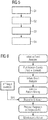
- the event analyzer 2 of the optical network 1 is adapted to perform a method as illustrated in the flowchart of Fig. 5 .
- the illustrated method comprises several main steps S1, S2, S3, S4.
- a first step S1 at least one set of historical multi-level events E representing different hierarchy levels of the respective optical network 1 can be recorded.
- the recorded multi-level events E can comprise different event types including information events, warning events and/or failure events.
- the multi-level events E can comprise events concerning components of the optical network 1 as illustrated in Fig. 1 and/or environmental events concerning the environment of the optical network.
- the multi-level events E recorded in step S1 can comprise events E from different hierarchy levels HL of the optical network 1 including system level events, subsystem level events, device level events, component level events and/or events E from different protocol layers PL of a data protocol stack implemented in the optical network 1.
- the recorded multi-level events E can comprise three different types of events including information events E inf , warning events E w and failure events E f .
- the information events E inf can indicate whether a temperature T of a component is within a predefined temperature range.
- An information event E inf can also indicate an optical power level or can indicate whether a device or component is reachable.
- the information event E inf can also for instance indicate whether a device or component responds to SNMP.
- a further example for an information event E inf is an event indicating that a new device or component within the optical network 1 has been found or detected.
- a further example for an information event E inf is an event indicating that an equalization operation has been performed successfully.
- warning events E w are for instance an event indicating a high temperature or a high power.
- a further example for a potentially warning event E w is that a DSP has been disabled for the respective device or component.
- a further example of a warning event E w is that a network scan has been started or that a maintenance of a component is demanded.
- a further example of a warning event E w is that an interruption has been detected.
- a third type of recorded multi-level events are failure events E F .
- failure events E F are for instance that an ROADM equalization error has occurred.
- Another example for a failure event E F is that a receiver I/P power is too low.
- a failure event E F may indicate that a LAN interface is inactive or that a laser of a component is shutdown.
- a further example of a failure event E F is that the received error rate becomes critical.
- multi-level events E received from different components of the optical network 1 including information events E inf , warning events E w and/or failure events E F .
- These multi-level events E including information, warning and/or failure events can come from different hierarchy levels HL of the optical network 1 and/or from different protocol layers PL of a data protocol stack.
- the event analyzer 2 of the optical network 1 comprises a centralized framework for event-based real-time event-driven diagnostics and/or prognostics of a network behaviour of the hierarchical optical network 1.
- the network nodes 3A, 3B forming the endpoints of a signal channel can provide system level events applied to the event analyzer 2.
- the amplifier site 4 may provide subsystem level events to the event analyzer 2 and the fiber site 5 including for instance a water sensor and an intrusion sensor may provide further subsystem level events and/or operational events to the event analyzer 2.
- the optical network 1 may comprise one or several network segments.
- One or more independent sets of historical multi-level events E can be recorded in a possible embodiment for different network segments of the optical network 1. Further, it is possible that one or more independent sets of historical multi-level events E are recorded for the same network segment of said optical network 1 representing different operation time periods of the respective network segment.
- the event patterns for different network segments of the optical network 1 can be determined and shared for recognized matching event patterns within the same or other network segments of the optical network 1 belonging to the same or different customers.
- the event analyzer 2 illustrated in Fig. 1 is adapted to mine in a step S2 machine learned event patterns within recorded sequences of multi-level events E.
- the event patterns can be mined in step S2 within recorded sequences of multi-level events according to predefined pattern mining boundaries. For instance, only event patterns that occur more frequently than a given threshold value are considered.
- a mining parameter boundary can comprise a minimum event pattern length, i.e. a minimum number of events E in an event pattern is required.
- a further possible predefined pattern mining parameter boundary can comprise specific target events, i.e. event messages to be mined by the event analyzer 2.
- a further exemplary predefined pattern mining parameter boundary used by the event analyzer 2 can comprise a desired event pattern number, i.e.
- a further example of a predefined pattern mining parameter boundary used by the event analyzer 2 may comprise a maximum sequence duration, i.e. a maximum admissible time duration of the event pattern.
- a further possible predefined pattern mining parameter boundary can be a minimum time interval between similar back-to-back events, i.e. all duplicate events within a clean-up window are purged automatically.
- a further predefined pattern mining parameter boundary can be that only events E are considered that occur within a predefined time period as simultaneous, i.e. simultaneous events E are aggregated.
- a further possible pattern mining parameter boundary can be the extraction of pattern instances and temporal dependencies, i.e. information about temporal dependencies between different event patterns are gathered.
- the event analyzer 2 of the optical network 1 is further adapted to map the determined mined event patterns in a step S3 to a multi-level network topology of the optical network 1 and/or to a channel connectivity of channels through the optical network 1.
- Event patterns are learned and used for diagnostics and prognostics purposes.
- the events E can be mapped to a multi-level network topology indicative of system, subsystem or device level associations related to data traffic. For instance, system level bit error rates BER, subsystem level amplifier gains and/or device level laser currents can be mapped in step S3 according to the network hierarchy of the optical network 1.
- the event analyzer 2 of the optical network 1 can perform a reasoning to draw conclusions for diagnostic and/or prognostic purposes from observed real-time multi-level target events.
- the event analyzer 2 can match in a step S4 observed real-time multi-level target events E received from the optical network 1 with at least one of the previously determined mined event patterns and can perform a unified cause and effect analysis of network states and/or network components of the respective optical network 1 for a recognized matching event pattern using the network topology and/or channel connectivity associated with the matching event pattern.
- the matching of at least one previously determined mined event pattern with the observed real time multi-level target events occurring in the optical network 1 and the unified cause and effect analysis of the recognized matching event pattern can be performed non-intrusively by the event analyzer 2.
- a calculated similarity can be assigned iteratively with respect to the existing previously determined event patterns and a probability that a recognized matching event pattern represents a root cause RC can be calculated in a reasoning session by a reasoning entity of the event analyzer 2.
- multi-level events and/or event patterns can be filtered, aggregated and/or sorted. For instance, lower-level events can be aggregated according to the hierarchy levels HL of the optical network 1 and the matching is performed by the event analyzer 2 on the basis of aggregated high-level events. Lower-level events can be aggregated in the hierarchy to the next hierarchy level so that only high-level reasoning is performed by the event analyzer 2. A lower-level reasoning can be triggered, if needed.
- the event analyzer 2 of the optical network 1 illustrated in Fig. 1 can have access to an event database EDB of the system.
- the event database EDB can comprise recorded multi-level events E that can be updated with observed real-time multi-level target events E.
- the event database EDB comprises the recorded set of historical multi-level events E representing different hierarchy levels HL and/or protocol layers PL of the optical network 1 and is updated continuously in a possible embodiment with observed real-time multi-level target events E of the optical network 1 included in the target event stream TES.
- the event analyzer 2 is adapted to mine machine learned event patterns within the recorded and updated sets of multi-level events representing different hierarchy levels HL and/or protocol layers PL of the optical network 1.
- the event analyzer 2 can be further adapted to map determined event patterns to a multi-level network topology of the optical network 1 and/or to a channel connectivity of channels provided via the optical network 1.
- the event analyzer 2 is further adapted to match in a reasoning session a sequence of observed real-time multi-level target events of the optical network 1 received by the event analyzer 2 in a target event stream TES with at least one of the previously determined mined event patterns adapted to perform a unified cause and effect analysis of network states and/or network components of the optical network 1 for the recognized matching event pattern using the network topology and/or channel connectivity associated with the matching event pattern.
- event patterns determined by the event analyzer 2 illustrated in Fig. 1 can be shared with other event analyzers 2 to recognize matching event patterns in the same or different network segments of the optical network 1. Further, it is possible to report event patterns determined by the event analyzer 2 to a central event analyzer of the optical network 1 to recognize a matching event pattern in the complete optical network 1. Event patterns with temporal dependencies can be scaled in time based on a geographical system size.
- optical fiber line and transmission equipment events E can be fed to the event analyzer 2 which may be located at an SDN controller or orchestrator unit of the network 1. It is also possible to deploy several event analyzers 2 based on different network segments and to share information to a common global or central event analyzer 2 of the network.
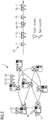
- Fig. 2 illustrates a typical meshed network topology of an optical network 1.
- a single unified failure may lead to a series of highly complex events E with an event stream ES which may impose an offline and time-consuming troubleshooting to identify and rectify the occurred fault within the optical network 1.
- a single failure or fault can trigger an event stream ES comprising a plurality of different events E including alarm events as illustrated in Fig. 2 .
- Fig. 3 illustrates a possible structure of an event analyzer framework according to a possible exemplary embodiment of the present invention.
- the event analyzer 2 of the optical network 1 may comprise in the illustrated implementation an event viewer entity 2A which is adapted to pull historical event streams ES together with network maps of the optical network 1 indicating the topology of the optical network 1 from a database.
- the historical event streams ES can comprise recorded sets of historical multi-level events E representing different hierarchy levels HL of the optical network 1. Historical event streams ES may or may not belong to the optical network 1 under analysis.
- a pattern mining entity 2B of the event analyzer 2 performs pattern mining. Machine learned event patterns are mined within the recorded historical multi-level events E. In the pattern mining step, hidden event patterns and their temporal relationships can be identified.
- the real-time target event data is input in a target event stream TES to a reasoning entity 2C adapted to perform a reasoning session.
- the observed received real-time multi-level target events E received from the optical network 1 are matched by the reasoning session entity 2C of the event analyzer 2 with at least one of the previously determined mined event patterns.
- the unified cause and effect analysis of the network states and/or network components of the optical network 1 can be performed for a recognized matching event pattern using the network topology and/or channel connectivity associated with the matching event pattern.
- the results may be displayed on a reporting dashboard entity 2D and predictive notifications on upcoming future events E can be issued in notifications.
- the event analyzer 2 can perform event-driven diagnostics and/or prognostics of the network behaviour of the investigated optical network 1.
- the event analyzer 2 may provide a reasoner diagnosis that event E1 and E3 are potential root causes RC of observed fault event E4.
- the reasoner prognosis issued by the event analyzer 2 can be for instance that in case of occurrences of event E1 and E3 fault event E4 is expected to happen after a predetermined time period.
- Fig. 4 illustrates an exemplary EDFA subsystem topology of an optical network 1 together with the event analyzer 2 according to an aspect of the present invention.
- the event analyzer framework 2 illustrated in Fig. 4 can be adapted to visualize identified event patterns for service loss due to various potential EDFA events E in the respective subsystem.
- the EDFA amplifier comprises in the illustrated example a control unit CU, a temperature sensor TS that measures the temperature T on the chip and a pump unit PU for optical amplifiers.
- the different components of the EDFA amplifier can supply event streams ES to the event analyzer 2 as illustrated in Fig. 4 .
- the transmitters (Tx) and receivers (Rx) can for instance notify failure events E1 to the event analyzer 2.
- Integrated amplifiers Amps can for instance provide EDFA power warning events E2 to the event analyzer 2. Further, they can provide EDFA gain control warning events E3.
- the VOA of the EDFA amplifier unit can provide for instance a failure EDFA VOA Power event E4 as illustrated in Fig. 4 .
- the pump unit PU can provide a warning event E5 and the temperature sensor TS can provide a warning event E6 as shown in Fig. 4 .
- the pump unit PU may provide an EDFA pump loss warning event E7 and the event analyzer 2 may further receive an EDFA power I/P failure event E8.
- Fig. 4 shows four exemplary target event patterns which the event analyzer 2 may receive from the optical network segment or optical subsystem also illustrated in Fig. 4 .
- the event analyzer 2 can apply a pattern mining algorithm to determine machine learned event patterns within recorded multi-level events.
- the observed real time multi-level target events received from the EDFA subsystem in Fig. 4 can be matched by the event analyzer 2 with at least one of the previously determined mined event patterns.
- a SPAM search procedure can be performed to explore a search space of event patterns. This can be done by appending single patterns recursively to each frequent event pattern to generate larger event patterns.
- the event analyzer 2 can be further adapted to define a calculated similarity with respect to existing previously determined event patterns.
- a probability that a recognized matching event pattern represents the root cause RC can be calculated by the event analyzer 2.
- a similarity index for a given event pattern X with respect to event pattern Y can be defined as the proportion of similar events in event pattern X which contains the event pattern Y.
- Fig. 6 illustrates a possible exemplary embodiment of a method for performing event-driven diagnostics and/or prognostics of a network behaviour of an optical hierarchical network 1 according to an aspect of the present invention.
- the event analyzer 2 of the optical network 1 can be initialized.
- historic network events can be pulled from the event database of the system.
- the event analyzer 2 is then initiated and executes in a further step a pattern mining of machine learned event patterns within the recorded multi-level events.
- observed real-time multi-level target events E received in an input livestream TES by the event analyzer 2 are matched with at least one of the previously determined mined event patterns.
- a unified root cause and effect analysis of network states and/or network components of the optical network 1 are performed by the event analyzer 2 for a recognized matching event pattern using the network topology and/or channel connectivity associated with the matching event pattern.
- a maintenance action can then be triggered by the event analyzer 2 as illustrated in the workflow of Fig. 6 .
- the event analyzer 2 can perform a network infrastructure diagnosis and prognosis in real time.
- the optical network 1 can comprise several components to provide an end-to-end connection between a transmitting node Tx and a receiving node Rx.
- a signal channel can be initiated at a transmitting node Tx-1 and transmitted through the EDFA amplifier to end at the receiving node Rx-1.
- each event E can comprise an event type and an information indicating its hierarchy level HL.
- the first event E1 error rate (Rx-n)
- the second event E2 can for instance indicate an EDFA power O/P of the event type "warning" belonging to the system hierarchy level "subsystem”.
- the third event E3 "internal gain control" can also be of the event type "warning" belonging to the further hierarchy level “device”.
- the fourth event E4 "EDFA VOA power" may be of the event type "failure" and may comprise the hierarchy level "device". Accordingly event E1 belongs to hierarchy level "system", event E2 belongs to the hierarchy level "subsystem” and the events E3, E4 belong to the hierarchy level "device". For the precedence of E1, E2, E3, E4 in the pathway the signal channel has traversed, the equipment is mapped. In this example, the mapping is quite simple since the first event E1 having the highest hierarchy level HL (system) is followed by event E2 (having the hierarchy level subsystem) and event E3 (gain) and E4 (EDFA VOA power) both belonging to the hierarchy level "device".
- a system level event of general error rate deterioration can be localized at a subsystem level event of the inline amplifier induced power excursions and further diagnosed down to its device level events including local gain control failure or EDFA VOA power for e.g. pump laser power loss.
- the general connectivity is a secondary outcome as the mapped topology is dependent on the signal channel at hand. For instance, for another channel, there can be events before or after event E1 and event E4, respectively.
- a matching of the observed real-time multi-level target events E of the optical network 1 with at least one of the previously determined mined event patterns is performed in a reasoning session followed by a unified cause and effect analysis of network states and/or network components of the optical network 1 for a recognized matching event pattern using the network topology and/or channel connectivity associated with the matching event pattern.
- the following sequence of events E for the illustrated amplifier subsystem may occur: a temperature high event, a fan speed high event, a laser power low event, a gain low event and a transmit power low event. If such an event pattern has been previously mined in case that the first three events appear in the received real time event data (temperature high event, fan speed high event and laser power low event) the likely cause for the third event (laser power low) would be the first event (temperature high event). Likewise, a likely effect of the third event (laser power low) would be the fifth event (transmit power low).
- the method can be performed for an optical network 1 where traffic is carried over physical or virtual connections between a plurality of network nodes.
- at least one set of events which can represent a system, a subsystem or device level network hierarchical levels can be received and recorded. It is possible to autonomously cluster concurrent events wherein both known and unknown event patterns are determined and updated in operation in a pattern mining step using in a possible implementation an event analyzer 2.
- the events E can comprise information, warning or failure events or physical or operational parameters together with their time of occurrence in the system.
- events E are mapped to the multi-level network topology, indicative of system, subsystem or device level associations related to the traffic. For instance, a system level BER, a subsystem level amplifier gain and/or a device level current can be mapped according to the network hierarchy of the optical network 1. From the detection of partial or full occurrence of an established event pattern, it is possible to identify in real time a reaction on multiple levels for the unified diagnosis and prognosis of network traffic deterioration. Unified refers to both backtracking for reactive root cause search for a current event E and forward looking for proactive root cause prognosis for future events E or actions in a single event pattern. It is possible to provide means for multi-level association aggregation obtaining network segments for cause and effect identification at a given network layer.
- multiple component level events can be aggregated to a subsystem event or multiple subsystem events to a system event. It is possible to use event patterns from one network segment for at least one or more unrelated network segments wherein a time scaling of event data based on geographical system size can be performed.
- the event stream ES can include configuration data, quality data and environmental data.
- the event analyzer 2 can comprise in a possible implementation an event viewer entity 2A, a pattern mining entity, a reasoning session entity 2C as well as a report building entity 2D.
- the determination of concurrent events can include autonomous data mining approaches. The method allows for a transfer and/or a sharing of learned knowledge among a plurality of unrelated network segments for initiating optimizations and in-operation training.
- a shared central database can be used for identified event pattern updates across a plurality of network environments and/or network segments.
- the event analyzer 2 and its constituents can comprise hardware components and/or software components or a combination of hardware and software components.
- the event analyzer 2 can be used to modify network maintenance cycles and/or perform improvements on a network design of the optical network 1.
- the method provides for global diagnostics and/or prognostics of the network behaviour of the hierarchical optical network 1 and incorporates both line and equipment failures including physical and operational system, subsystem and device faults.
- the method and system 1 according to the present invention have low memory requirements due to the event-based diagnostics rather than performing a continuous manifold physical parameters monitoring.
- the method employs an event-driven fault learning architecture and provides a self-regulated method operation. An online learning can be performed of both known and unknown network faults.
- the fault information can be shared in real time with other network resources.
- the method and system according to the present invention provides a framework where optical system, subsystem and optical line alarms can continuously be shared with a centralized controller wherein an event analyzer 2 can be implemented.
- the method and system 1 allows to autonomously learn and respond to vulnerable event patterns including information events, warning events and failure events and is even able to predict failures or faults before they occur in the optical network 1.
- a system level event of traffic deterioration can be localized or mapped to a subsystem level event of an inline EDFA amplifier used for power excursion and further diagnosed down to its device level events of local gain control failure, pump laser power loss, passive insertion loss or temperature variations.
- the events occurring in levels below the system level i.e.
- the method and system according to the present invention reduce significantly service downtimes due to its active approach.
- the method performs diagnostics and/or prognostics not only locally on a single device or node but in a global manner.
- the method and system according to the present invention consolidates both diagnosis and prognosis in a unified real-time framework allowing for a multi-layered proactive fault identification and to provide recommended actions.
- the method according to the present invention can be performed non-intrusively on observed real-time multi-level target events derived from the optical network 1.
- the optical network 1 may comprise several network segments connected to each other e.g. by ROADMs.
- an associated network segment event analyzer 2 can be provided for each network segment.
- the different network segment event analyzers 2 can further be connected to a central event analyzer 2 of the whole optical network system 1.
- the different event analyzers 2 can share a common event database EDB.
- the method and system 1 according to the present invention provides for a very short reaction time in case that failures or faults occur within the optical network 1.
- the method and system 1 further allows for a proactive exchange and/or repair of network equipment and network lines.
Landscapes
- Engineering & Computer Science (AREA)
- Physics & Mathematics (AREA)
- Electromagnetism (AREA)
- Computer Networks & Wireless Communication (AREA)
- Signal Processing (AREA)
- Computing Systems (AREA)
- Theoretical Computer Science (AREA)
- Software Systems (AREA)
- Data Mining & Analysis (AREA)
- Evolutionary Computation (AREA)
- Medical Informatics (AREA)
- Computer Vision & Pattern Recognition (AREA)
- General Engineering & Computer Science (AREA)
- General Physics & Mathematics (AREA)
- Mathematical Physics (AREA)
- Artificial Intelligence (AREA)
- Data Exchanges In Wide-Area Networks (AREA)
Priority Applications (2)
| Application Number | Priority Date | Filing Date | Title |
|---|---|---|---|
| EP18155570.7A EP3525366B1 (fr) | 2018-02-07 | 2018-02-07 | Procédé et dispositif pour la réalisation de diagnostics ou de pronostics commandés par événement d'un comportement de réseau d'un réseau optique hiérarchique |
| US16/267,011 US10735099B2 (en) | 2018-02-07 | 2019-02-04 | Method and apparatus for performing event-driven diagnostics or prognostics of a network behaviour of a hierarchical optical network |
Applications Claiming Priority (1)
| Application Number | Priority Date | Filing Date | Title |
|---|---|---|---|
| EP18155570.7A EP3525366B1 (fr) | 2018-02-07 | 2018-02-07 | Procédé et dispositif pour la réalisation de diagnostics ou de pronostics commandés par événement d'un comportement de réseau d'un réseau optique hiérarchique |
Publications (2)
| Publication Number | Publication Date |
|---|---|
| EP3525366A1 true EP3525366A1 (fr) | 2019-08-14 |
| EP3525366B1 EP3525366B1 (fr) | 2021-07-28 |
Family
ID=61188625
Family Applications (1)
| Application Number | Title | Priority Date | Filing Date |
|---|---|---|---|
| EP18155570.7A Active EP3525366B1 (fr) | 2018-02-07 | 2018-02-07 | Procédé et dispositif pour la réalisation de diagnostics ou de pronostics commandés par événement d'un comportement de réseau d'un réseau optique hiérarchique |
Country Status (2)
| Country | Link |
|---|---|
| US (1) | US10735099B2 (fr) |
| EP (1) | EP3525366B1 (fr) |
Families Citing this family (6)
| Publication number | Priority date | Publication date | Assignee | Title |
|---|---|---|---|---|
| JP6978687B2 (ja) * | 2018-03-08 | 2021-12-08 | 日本電信電話株式会社 | 監視装置及び監視方法 |
| JP7059903B2 (ja) * | 2018-11-14 | 2022-04-26 | 富士通株式会社 | 通信装置、及び通信方法 |
| JP7737111B2 (ja) * | 2021-11-16 | 2025-09-10 | Ntt株式会社 | 異常発生箇所判定装置、異常発生箇所判定方法及びプログラム |
| US12368507B2 (en) * | 2022-08-15 | 2025-07-22 | At&T Intellectual Property I, L.P. | DWDM path outage prediction and alternative path recommendation |
| US12332737B2 (en) * | 2023-03-08 | 2025-06-17 | Nxp B.V. | Method and apparatus for fault indication propagation and fault masking in a hierarchical arrangement of systems |
| US12334974B1 (en) * | 2023-10-03 | 2025-06-17 | Citibank, N.A. | Optic power monitoring system |
Citations (4)
| Publication number | Priority date | Publication date | Assignee | Title |
|---|---|---|---|---|
| EP0810807A2 (fr) * | 1996-05-31 | 1997-12-03 | Nortel Networks Corporation | Méthode et dispositif pour analyser les données de réseau |
| US5771274A (en) * | 1996-06-21 | 1998-06-23 | Mci Communications Corporation | Topology-based fault analysis in telecommunications networks |
| US20130190095A1 (en) * | 2008-11-18 | 2013-07-25 | Spielo International ULC | Faults and Performance Issue Prediction |
| US20150254969A1 (en) * | 2014-03-10 | 2015-09-10 | Verizon Patent And Licensing Inc. | Method and system for providing aggregated network alarms |
Family Cites Families (7)
| Publication number | Priority date | Publication date | Assignee | Title |
|---|---|---|---|---|
| GB9303640D0 (en) | 1993-02-23 | 1993-04-07 | British Telecomm | Object-oriented correlation |
| US6690274B1 (en) * | 1998-05-01 | 2004-02-10 | Invensys Systems, Inc. | Alarm analysis tools method and apparatus |
| US8676945B2 (en) | 2005-04-14 | 2014-03-18 | Verizon Business Global Llc | Method and system for processing fault alarms and maintenance events in a managed network services system |
| US10483003B1 (en) * | 2013-08-12 | 2019-11-19 | Cerner Innovation, Inc. | Dynamically determining risk of clinical condition |
| US20170223034A1 (en) * | 2016-01-29 | 2017-08-03 | Acalvio Technologies, Inc. | Classifying an email as malicious |
| US10326796B1 (en) * | 2016-04-26 | 2019-06-18 | Acalvio Technologies, Inc. | Dynamic security mechanisms for mixed networks |
| US20190228085A1 (en) * | 2018-01-19 | 2019-07-25 | Ca, Inc. | Log file pattern identifier |
-
2018
- 2018-02-07 EP EP18155570.7A patent/EP3525366B1/fr active Active
-
2019
- 2019-02-04 US US16/267,011 patent/US10735099B2/en active Active
Patent Citations (4)
| Publication number | Priority date | Publication date | Assignee | Title |
|---|---|---|---|---|
| EP0810807A2 (fr) * | 1996-05-31 | 1997-12-03 | Nortel Networks Corporation | Méthode et dispositif pour analyser les données de réseau |
| US5771274A (en) * | 1996-06-21 | 1998-06-23 | Mci Communications Corporation | Topology-based fault analysis in telecommunications networks |
| US20130190095A1 (en) * | 2008-11-18 | 2013-07-25 | Spielo International ULC | Faults and Performance Issue Prediction |
| US20150254969A1 (en) * | 2014-03-10 | 2015-09-10 | Verizon Patent And Licensing Inc. | Method and system for providing aggregated network alarms |
Also Published As
| Publication number | Publication date |
|---|---|
| US20190245620A1 (en) | 2019-08-08 |
| EP3525366B1 (fr) | 2021-07-28 |
| US10735099B2 (en) | 2020-08-04 |
Similar Documents
| Publication | Publication Date | Title |
|---|---|---|
| US10735099B2 (en) | Method and apparatus for performing event-driven diagnostics or prognostics of a network behaviour of a hierarchical optical network | |
| US11894969B2 (en) | Identifying root causes of network service degradation | |
| CA2564724C (fr) | Systeme automatique de telesurveillance et de diagnostic et methode de communication entre un controleur logique programmable et une unite centrale | |
| US9571334B2 (en) | Systems and methods for correlating alarms in a network | |
| US11348023B2 (en) | Identifying locations and causes of network faults | |
| US7257744B2 (en) | System and method for fault diagnosis using distributed alarm correlation | |
| CN106130761B (zh) | 数据中心的故障网络设备的识别方法和装置 | |
| US6907549B2 (en) | Error detection in communication systems | |
| EP1279211A4 (fr) | Appareil de raisonnement fonde sur la topologie permettant d'analyser la cause fondamentale des defauts d'un reseau | |
| Rafique et al. | Analytics-driven fault discovery and diagnosis for cognitive root cause analysis | |
| CN101753382A (zh) | 一种自适应网络故障监控定位安全模型的构建方法 | |
| CN116346656B (zh) | 物联网设备的链路状态检测方法及系统 | |
| CN105005644B (zh) | 一种检测三相异步电动机故障的方法 | |
| KR102680066B1 (ko) | 네트워크 케이블 품질 모니터링이 가능한 지능형 통합배선반 | |
| KR20190132223A (ko) | 네트워크 장애 원인 분석 장치 및 방법 | |
| CN114726708A (zh) | 一种基于人工智能的网元设备故障预测方法及系统 | |
| Pinzón et al. | Real-time health condition monitoring of SCADA infrastructure of power transmission systems control centers | |
| WO2017050621A1 (fr) | Diagnostic de défaillances | |
| JP5292929B2 (ja) | 監視装置 | |
| US11477070B1 (en) | Identifying root causes of network service degradation | |
| CN115348146A (zh) | 业务异常的根因确定方法、装置及系统 | |
| Rafique et al. | TSDN-enabled network assurance: a cognitive fault detection architecture | |
| KR102779650B1 (ko) | 네트워크 케이블 품질 모니터링이 가능한 지능형 통합배선반을 이용한 모니터링 방법 | |
| Bennacer et al. | Scalable and fast root cause analysis using inter cluster inference | |
| US12335053B2 (en) | Systems and methods for managing PRP networks |
Legal Events
| Date | Code | Title | Description |
|---|---|---|---|
| PUAI | Public reference made under article 153(3) epc to a published international application that has entered the european phase |
Free format text: ORIGINAL CODE: 0009012 |
|
| STAA | Information on the status of an ep patent application or granted ep patent |
Free format text: STATUS: THE APPLICATION HAS BEEN PUBLISHED |
|
| AK | Designated contracting states |
Kind code of ref document: A1 Designated state(s): AL AT BE BG CH CY CZ DE DK EE ES FI FR GB GR HR HU IE IS IT LI LT LU LV MC MK MT NL NO PL PT RO RS SE SI SK SM TR |
|
| AX | Request for extension of the european patent |
Extension state: BA ME |
|
| STAA | Information on the status of an ep patent application or granted ep patent |
Free format text: STATUS: REQUEST FOR EXAMINATION WAS MADE |
|
| 17P | Request for examination filed |
Effective date: 20190910 |
|
| RBV | Designated contracting states (corrected) |
Designated state(s): AL AT BE BG CH CY CZ DE DK EE ES FI FR GB GR HR HU IE IS IT LI LT LU LV MC MK MT NL NO PL PT RO RS SE SI SK SM TR |
|
| GRAP | Despatch of communication of intention to grant a patent |
Free format text: ORIGINAL CODE: EPIDOSNIGR1 |
|
| STAA | Information on the status of an ep patent application or granted ep patent |
Free format text: STATUS: GRANT OF PATENT IS INTENDED |
|
| INTG | Intention to grant announced |
Effective date: 20210317 |
|
| GRAS | Grant fee paid |
Free format text: ORIGINAL CODE: EPIDOSNIGR3 |
|
| GRAA | (expected) grant |
Free format text: ORIGINAL CODE: 0009210 |
|
| STAA | Information on the status of an ep patent application or granted ep patent |
Free format text: STATUS: THE PATENT HAS BEEN GRANTED |
|
| AK | Designated contracting states |
Kind code of ref document: B1 Designated state(s): AL AT BE BG CH CY CZ DE DK EE ES FI FR GB GR HR HU IE IS IT LI LT LU LV MC MK MT NL NO PL PT RO RS SE SI SK SM TR |
|
| REG | Reference to a national code |
Ref country code: GB Ref legal event code: FG4D |
|
| REG | Reference to a national code |
Ref country code: CH Ref legal event code: EP |
|
| REG | Reference to a national code |
Ref country code: DE Ref legal event code: R096 Ref document number: 602018020639 Country of ref document: DE |
|
| REG | Reference to a national code |
Ref country code: AT Ref legal event code: REF Ref document number: 1415663 Country of ref document: AT Kind code of ref document: T Effective date: 20210815 |
|
| REG | Reference to a national code |
Ref country code: IE Ref legal event code: FG4D |
|
| REG | Reference to a national code |
Ref country code: LT Ref legal event code: MG9D |
|
| REG | Reference to a national code |
Ref country code: NL Ref legal event code: MP Effective date: 20210728 |
|
| REG | Reference to a national code |
Ref country code: AT Ref legal event code: MK05 Ref document number: 1415663 Country of ref document: AT Kind code of ref document: T Effective date: 20210728 |
|
| PG25 | Lapsed in a contracting state [announced via postgrant information from national office to epo] |
Ref country code: SE Free format text: LAPSE BECAUSE OF FAILURE TO SUBMIT A TRANSLATION OF THE DESCRIPTION OR TO PAY THE FEE WITHIN THE PRESCRIBED TIME-LIMIT Effective date: 20210728 Ref country code: RS Free format text: LAPSE BECAUSE OF FAILURE TO SUBMIT A TRANSLATION OF THE DESCRIPTION OR TO PAY THE FEE WITHIN THE PRESCRIBED TIME-LIMIT Effective date: 20210728 Ref country code: HR Free format text: LAPSE BECAUSE OF FAILURE TO SUBMIT A TRANSLATION OF THE DESCRIPTION OR TO PAY THE FEE WITHIN THE PRESCRIBED TIME-LIMIT Effective date: 20210728 Ref country code: FI Free format text: LAPSE BECAUSE OF FAILURE TO SUBMIT A TRANSLATION OF THE DESCRIPTION OR TO PAY THE FEE WITHIN THE PRESCRIBED TIME-LIMIT Effective date: 20210728 Ref country code: ES Free format text: LAPSE BECAUSE OF FAILURE TO SUBMIT A TRANSLATION OF THE DESCRIPTION OR TO PAY THE FEE WITHIN THE PRESCRIBED TIME-LIMIT Effective date: 20210728 Ref country code: PT Free format text: LAPSE BECAUSE OF FAILURE TO SUBMIT A TRANSLATION OF THE DESCRIPTION OR TO PAY THE FEE WITHIN THE PRESCRIBED TIME-LIMIT Effective date: 20211129 Ref country code: NL Free format text: LAPSE BECAUSE OF FAILURE TO SUBMIT A TRANSLATION OF THE DESCRIPTION OR TO PAY THE FEE WITHIN THE PRESCRIBED TIME-LIMIT Effective date: 20210728 Ref country code: NO Free format text: LAPSE BECAUSE OF FAILURE TO SUBMIT A TRANSLATION OF THE DESCRIPTION OR TO PAY THE FEE WITHIN THE PRESCRIBED TIME-LIMIT Effective date: 20211028 Ref country code: BG Free format text: LAPSE BECAUSE OF FAILURE TO SUBMIT A TRANSLATION OF THE DESCRIPTION OR TO PAY THE FEE WITHIN THE PRESCRIBED TIME-LIMIT Effective date: 20211028 Ref country code: AT Free format text: LAPSE BECAUSE OF FAILURE TO SUBMIT A TRANSLATION OF THE DESCRIPTION OR TO PAY THE FEE WITHIN THE PRESCRIBED TIME-LIMIT Effective date: 20210728 Ref country code: LT Free format text: LAPSE BECAUSE OF FAILURE TO SUBMIT A TRANSLATION OF THE DESCRIPTION OR TO PAY THE FEE WITHIN THE PRESCRIBED TIME-LIMIT Effective date: 20210728 |
|
| PG25 | Lapsed in a contracting state [announced via postgrant information from national office to epo] |
Ref country code: PL Free format text: LAPSE BECAUSE OF FAILURE TO SUBMIT A TRANSLATION OF THE DESCRIPTION OR TO PAY THE FEE WITHIN THE PRESCRIBED TIME-LIMIT Effective date: 20210728 Ref country code: LV Free format text: LAPSE BECAUSE OF FAILURE TO SUBMIT A TRANSLATION OF THE DESCRIPTION OR TO PAY THE FEE WITHIN THE PRESCRIBED TIME-LIMIT Effective date: 20210728 Ref country code: GR Free format text: LAPSE BECAUSE OF FAILURE TO SUBMIT A TRANSLATION OF THE DESCRIPTION OR TO PAY THE FEE WITHIN THE PRESCRIBED TIME-LIMIT Effective date: 20211029 |
|
| PG25 | Lapsed in a contracting state [announced via postgrant information from national office to epo] |
Ref country code: DK Free format text: LAPSE BECAUSE OF FAILURE TO SUBMIT A TRANSLATION OF THE DESCRIPTION OR TO PAY THE FEE WITHIN THE PRESCRIBED TIME-LIMIT Effective date: 20210728 |
|
| REG | Reference to a national code |
Ref country code: DE Ref legal event code: R097 Ref document number: 602018020639 Country of ref document: DE |
|
| PG25 | Lapsed in a contracting state [announced via postgrant information from national office to epo] |
Ref country code: SM Free format text: LAPSE BECAUSE OF FAILURE TO SUBMIT A TRANSLATION OF THE DESCRIPTION OR TO PAY THE FEE WITHIN THE PRESCRIBED TIME-LIMIT Effective date: 20210728 Ref country code: SK Free format text: LAPSE BECAUSE OF FAILURE TO SUBMIT A TRANSLATION OF THE DESCRIPTION OR TO PAY THE FEE WITHIN THE PRESCRIBED TIME-LIMIT Effective date: 20210728 Ref country code: RO Free format text: LAPSE BECAUSE OF FAILURE TO SUBMIT A TRANSLATION OF THE DESCRIPTION OR TO PAY THE FEE WITHIN THE PRESCRIBED TIME-LIMIT Effective date: 20210728 Ref country code: EE Free format text: LAPSE BECAUSE OF FAILURE TO SUBMIT A TRANSLATION OF THE DESCRIPTION OR TO PAY THE FEE WITHIN THE PRESCRIBED TIME-LIMIT Effective date: 20210728 Ref country code: CZ Free format text: LAPSE BECAUSE OF FAILURE TO SUBMIT A TRANSLATION OF THE DESCRIPTION OR TO PAY THE FEE WITHIN THE PRESCRIBED TIME-LIMIT Effective date: 20210728 Ref country code: AL Free format text: LAPSE BECAUSE OF FAILURE TO SUBMIT A TRANSLATION OF THE DESCRIPTION OR TO PAY THE FEE WITHIN THE PRESCRIBED TIME-LIMIT Effective date: 20210728 |
|
| PLBE | No opposition filed within time limit |
Free format text: ORIGINAL CODE: 0009261 |
|
| STAA | Information on the status of an ep patent application or granted ep patent |
Free format text: STATUS: NO OPPOSITION FILED WITHIN TIME LIMIT |
|
| 26N | No opposition filed |
Effective date: 20220429 |
|
| PG25 | Lapsed in a contracting state [announced via postgrant information from national office to epo] |
Ref country code: IT Free format text: LAPSE BECAUSE OF FAILURE TO SUBMIT A TRANSLATION OF THE DESCRIPTION OR TO PAY THE FEE WITHIN THE PRESCRIBED TIME-LIMIT Effective date: 20210728 |
|
| PG25 | Lapsed in a contracting state [announced via postgrant information from national office to epo] |
Ref country code: MC Free format text: LAPSE BECAUSE OF FAILURE TO SUBMIT A TRANSLATION OF THE DESCRIPTION OR TO PAY THE FEE WITHIN THE PRESCRIBED TIME-LIMIT Effective date: 20210728 |
|
| REG | Reference to a national code |
Ref country code: CH Ref legal event code: PL |
|
| REG | Reference to a national code |
Ref country code: BE Ref legal event code: MM Effective date: 20220228 |
|
| PG25 | Lapsed in a contracting state [announced via postgrant information from national office to epo] |
Ref country code: LU Free format text: LAPSE BECAUSE OF NON-PAYMENT OF DUE FEES Effective date: 20220207 |
|
| PG25 | Lapsed in a contracting state [announced via postgrant information from national office to epo] |
Ref country code: FR Free format text: LAPSE BECAUSE OF NON-PAYMENT OF DUE FEES Effective date: 20220228 |
|
| PG25 | Lapsed in a contracting state [announced via postgrant information from national office to epo] |
Ref country code: LI Free format text: LAPSE BECAUSE OF NON-PAYMENT OF DUE FEES Effective date: 20220228 Ref country code: IE Free format text: LAPSE BECAUSE OF NON-PAYMENT OF DUE FEES Effective date: 20220207 Ref country code: CH Free format text: LAPSE BECAUSE OF NON-PAYMENT OF DUE FEES Effective date: 20220228 |
|
| PG25 | Lapsed in a contracting state [announced via postgrant information from national office to epo] |
Ref country code: BE Free format text: LAPSE BECAUSE OF NON-PAYMENT OF DUE FEES Effective date: 20220228 |
|
| P01 | Opt-out of the competence of the unified patent court (upc) registered |
Effective date: 20230630 |
|
| REG | Reference to a national code |
Ref country code: DE Ref legal event code: R081 Ref document number: 602018020639 Country of ref document: DE Owner name: ADTRAN NETWORKS SE, DE Free format text: FORMER OWNER: ADVA OPTICAL NETWORKING SE, 98617 MEININGEN, DE |
|
| PG25 | Lapsed in a contracting state [announced via postgrant information from national office to epo] |
Ref country code: MK Free format text: LAPSE BECAUSE OF FAILURE TO SUBMIT A TRANSLATION OF THE DESCRIPTION OR TO PAY THE FEE WITHIN THE PRESCRIBED TIME-LIMIT Effective date: 20210728 Ref country code: CY Free format text: LAPSE BECAUSE OF FAILURE TO SUBMIT A TRANSLATION OF THE DESCRIPTION OR TO PAY THE FEE WITHIN THE PRESCRIBED TIME-LIMIT Effective date: 20210728 |
|
| PG25 | Lapsed in a contracting state [announced via postgrant information from national office to epo] |
Ref country code: HU Free format text: LAPSE BECAUSE OF FAILURE TO SUBMIT A TRANSLATION OF THE DESCRIPTION OR TO PAY THE FEE WITHIN THE PRESCRIBED TIME-LIMIT; INVALID AB INITIO Effective date: 20180207 |
|
| PG25 | Lapsed in a contracting state [announced via postgrant information from national office to epo] |
Ref country code: TR Free format text: LAPSE BECAUSE OF FAILURE TO SUBMIT A TRANSLATION OF THE DESCRIPTION OR TO PAY THE FEE WITHIN THE PRESCRIBED TIME-LIMIT Effective date: 20210728 |
|
| PG25 | Lapsed in a contracting state [announced via postgrant information from national office to epo] |
Ref country code: MT Free format text: LAPSE BECAUSE OF FAILURE TO SUBMIT A TRANSLATION OF THE DESCRIPTION OR TO PAY THE FEE WITHIN THE PRESCRIBED TIME-LIMIT Effective date: 20210728 |
|
| PGFP | Annual fee paid to national office [announced via postgrant information from national office to epo] |
Ref country code: GB Payment date: 20260219 Year of fee payment: 9 |
|
| PGFP | Annual fee paid to national office [announced via postgrant information from national office to epo] |
Ref country code: DE Payment date: 20260217 Year of fee payment: 9 |