EP3525549A1 - Dispositif de génération de chaleur par induction magnétique - Google Patents
Dispositif de génération de chaleur par induction magnétique Download PDFInfo
- Publication number
- EP3525549A1 EP3525549A1 EP17857886.0A EP17857886A EP3525549A1 EP 3525549 A1 EP3525549 A1 EP 3525549A1 EP 17857886 A EP17857886 A EP 17857886A EP 3525549 A1 EP3525549 A1 EP 3525549A1
- Authority
- EP
- European Patent Office
- Prior art keywords
- discs
- generating heat
- magnetic induction
- disc
- induction according
- Prior art date
- Legal status (The legal status is an assumption and is not a legal conclusion. Google has not performed a legal analysis and makes no representation as to the accuracy of the status listed.)
- Withdrawn
Links
- 230000006698 induction Effects 0.000 title claims abstract description 20
- 239000000463 material Substances 0.000 claims abstract description 40
- 239000012530 fluid Substances 0.000 claims abstract description 23
- 230000005540 biological transmission Effects 0.000 claims description 7
- 229910052782 aluminium Inorganic materials 0.000 claims description 3
- XAGFODPZIPBFFR-UHFFFAOYSA-N aluminium Chemical compound [Al] XAGFODPZIPBFFR-UHFFFAOYSA-N 0.000 claims description 3
- 230000002093 peripheral effect Effects 0.000 claims description 3
- 238000007789 sealing Methods 0.000 claims description 3
- 238000010438 heat treatment Methods 0.000 description 8
- 238000005265 energy consumption Methods 0.000 description 4
- 239000004020 conductor Substances 0.000 description 2
- RYGMFSIKBFXOCR-UHFFFAOYSA-N Copper Chemical compound [Cu] RYGMFSIKBFXOCR-UHFFFAOYSA-N 0.000 description 1
- 238000013459 approach Methods 0.000 description 1
- 229910052802 copper Inorganic materials 0.000 description 1
- 239000010949 copper Substances 0.000 description 1
- 230000020169 heat generation Effects 0.000 description 1
- 238000004519 manufacturing process Methods 0.000 description 1
- 229910052751 metal Inorganic materials 0.000 description 1
- 239000002184 metal Substances 0.000 description 1
- 230000000717 retained effect Effects 0.000 description 1
Images



Classifications
-
- H—ELECTRICITY
- H05—ELECTRIC TECHNIQUES NOT OTHERWISE PROVIDED FOR
- H05B—ELECTRIC HEATING; ELECTRIC LIGHT SOURCES NOT OTHERWISE PROVIDED FOR; CIRCUIT ARRANGEMENTS FOR ELECTRIC LIGHT SOURCES, IN GENERAL
- H05B6/00—Heating by electric, magnetic or electromagnetic fields
- H05B6/02—Induction heating
- H05B6/10—Induction heating apparatus, other than furnaces, for specific applications
- H05B6/105—Induction heating apparatus, other than furnaces, for specific applications using a susceptor
- H05B6/109—Induction heating apparatus, other than furnaces, for specific applications using a susceptor using magnets rotating with respect to a susceptor
Definitions
- the present invention relates to heat generation for heating applications, proposing a device that allows heat to be produced by means of magnetic induction under cost-effective conditions for heating of fluids or similar applications.
- a device for generating heat by magnetic induction is proposed, based on magnet movement, which achieves an efficiency that improves the performance of known solutions in that regard and, consequently, the application capacity.
- the device for generating heat by magnetic induction comprises an element of thermoconductive material with a channel for circulating a fluid to be heated, and a set of discs with permanent magnets facing the element of thermoconductive material and which are designed to exert a variable magnetic field on the element of thermoconductive material.
- the set of discs comprises first motorised discs and at least one free-rotating second disc, wherein the first discs are arranged around the second disc, such that the second disc is rotated by the magnetic influence exerted by the permanent magnets of the first discs.
- the heat generated on the element of thermoconductive material is a function of the number of magnetic field changes and, therefore, of the number of permanent magnets incorporated in the discs and their rotational speed.
- the device and the invention propose to use at least one second disc that rotates due to the magnetic influence exerted by the first discs that are arranged around the second disc, which allows reducing the energy consumption necessary to rotate the set of discs, thus increasing the functional performance of the device.
- the channel for circulating a fluid is a groove that is directly made on a face of the element of thermoconductive material, such that the fluid is in direct contact with the element to be heated.
- the channel has a rough surface for increasing the fluid contact area, and thus creating a turbulent fluid flow that optimises thermal transfer.
- the closure cap On the face of the element of thermoconductive material that has the channel there is a closure cap with a sealing gasket that establishes a tight seal between the element and the closure cap and, therefore, prevents possible leaks that may occur in the channel through which the fluid to be heated circulates.
- the closure cap may be of a thermoconductive material, such as aluminum.
- the element of thermoconductive material has a slotted distribution on the face opposite to where the channel is, such that the surface exposed to the variable magnetic field generated by the permanent magnets is increased, while said slotted zone is heated faster than the rest of the element material.
- the slotted distribution has a circular shape reciprocal to the shape of the set of discs that facilitates rotation of the discs.
- the set of discs comprises four first discs arranged according to a quadrangular peripheral distribution and a second disc that is arranged in the centre of the distribution formed by the first discs.
- the discs comprise a disc body with housings for the permanent magnets, a rotation shaft and a first and a second support that retain the permanent magnets in the housings.
- the first support has a first inner threaded surface threading onto a reciprocal outer threaded surface of a first end of the rotation shaft, while the second support has a second inner threaded surface threading onto a reciprocal outer threaded surface of the disc body.
- the rotation shaft of the first discs has a second end with a grooved zone for receiving a transmission means connecting the first discs in rotation, while the rotation shaft of one of the first discs is coupled to a drive motor, such that one of the first discs is driven directly by the motor while the rest of the first discs are driven through the transmission means, the second disc being rotated by the magnetic influence exerted by the permanent magnets of the first discs.
- the device for generating heat object of the invention results from constructive and functional features that make it advantageous for the function for which it is intended, its embodiment taking on a life of its own and preferential character over conventional devices for the same application.
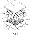
- the object of the invention relates to a device for generating heat by means of magnetic induction, comprising an element (1) of thermoconductive material such as aluminum and a set of discs (2) with permanent magnets (3) that are arranged facing the element (1) of thermoconductive material, wherein the discs (2) with permanent magnets (3) are rotatably driven causing a variable magnetic field that expands over the element (1) of thermoconductive material heating it.
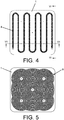
- the element (1) of thermoconductive material has a coil-shaped channel (4) through which a fluid to be heated circulates.
- each disc (2) The permanent magnets (3) of each disc (2) are arranged radially according to an alternating polarity distribution, so that they exert a variable magnetic field that causes successive magnetisations and demagnetisations of the thermoconductive material of the element (1), which results in an electromagnetic loss that produces a heat that by thermal transmission heats the fluid of the channel (4).
- Said element (1) of thermoconductive material is a block preferably of flat configuration that, on one of its larger faces, has the channel (4) for the circulation of fluid.
- the channel (4) is, for example, a groove that is directly made on the element (1) of thermoconductive material, such that the fluid to be heated circulating in the channel (4) is in direct contact with the thermoconductive material, maximising thermal transfer.
- a fluid inlet (5) and outlet (6) to the channel (4) are arranged on one of the smaller faces of the element (1) of thermoconductive material.
- the closure cap (7) On the larger face of the element (1) of thermoconductive material having the channel (4) there is a closure cap (7) with a sealing gasket (8) that establishes a tight seal between the element (1) of thermoconductive material and the closure cap (7) to prevent fluid leaks from the channel (4).
- the closure cap (7) is of a thermoconductive material, for example of the same material as the element (1), such that heat transfer to the channel fluid (4) is optimised.
- the channel (4) has a rough surface that allows increasing the contact area with the fluid circulating through the channel (4), thereby improving the transmission of heat to the fluid.
- the rough surface of the channel (4) may be protrusions, fins, or any other shape that causes turbulent flow of the fluid circulating through the interior of the channel 4, thereby increasing heating efficiency.
- the element (1) of thermoconductive material has a slotted distribution (9) on the larger face opposite the other larger face wherein the channel (4) is arranged, said slotted distribution increases the surface and allows faster heating of the element (1).
- the slotted distribution (9) has a circular shape reciprocal to that of the discs (2), which enhances the rotation of the discs (2) thus reducing the energy consumption for their driving.
- the set of discs (2) with permanent magnets (3) comprises first motorised discs (2.1) and at least one free-rotating second disc (2.2).
- the first discs (2.1) are arranged around the second disc (2.2), so that the permanent magnets (3) of the first discs (2.1) generate a magnetic influence on the permanent magnets of the second disc (2.2) causing their rotation, thereby optimising the energy consumption of the device for driving the set of discs (2).
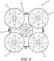
- the device comprises four motorised discs (2.1) and a free-rotating disc (2.2), thus the set of discs (2) is formed by four first discs (2.1) arranged according to a quadrangular peripheral distribution surrounding a second disc (2.2) that is arranged in the centre of said quadrangular distribution close to the first discs (2.1).
- the number of permanent magnets (3) incorporated in each disc (2) is an even number, so that an alternating polarity distribution is obtained in each disc (2).
- the permanent magnets (13) have a polarity on their upper face and an opposite polarity on their lower face, such that the generated magnetic field is directed in a direction perpendicular to the faces of the permanent magnets (3), and therefore the magnetic field is directed towards the element (1) to be heated since the discs (2) are arranged facing and parallel to the element (1) to be heated.
- the first discs (2.1) comprise a disc body (10) with housings (11) for the permanent magnets (3) on its upper face, a rotation shaft (12) extending in the axial direction of the disc (2.1) and supports (13, 14) for the permanent magnets (3) closing the housings (11) of the disc body (10).
- the rotation shaft (12) has a first end (12.1) that is arrangeable in a housing (15) of the element (1) of thermoconductive material (see Figure 5 ) and a second end (12.2) that is arrangeable in a housing (16) of a support plate (17) of the device (see Figure 1 ), such that the discs (2) are arranged with the possibility of rotation between the element (1) of thermoconductive material and the support plate (16).
- the rotation shaft (12) has at its second end (12.2) a grooved zone (18) for receiving a transmission means (19), such as a belt, distribution chain, or the like, which rotationally connects the first discs (2.1).
- a transmission means (19) such as a belt, distribution chain, or the like, which rotationally connects the first discs (2.1).
- the rotation shaft (12) of one of the first discs (2.1) is directly coupled to a drive motor (20) arranged in the support plate (17), such that the rest of the first discs (2.1) are motorised through the transmission means (19) that transmits the rotation of the drive motor (20).
- each first disc (2.1) has an independent drive motor (20), but the rotation of the second disc (2.2) is always caused by the magnetic influence exerted by the permanent magnets (3) of the first discs (2.2) located near their surroundings.
- the first support (13) has a first inner threaded surface threading onto a reciprocal outer threaded surface of the first end (12.1) of the rotation shaft (12), while the second support (14) has a second inner threaded surface threading onto a reciprocal outer threaded surface of the disc body (11), such that the permanent magnets (3) are retained in the housings (11) of the disc body (10) by means of the supports (13, 14) preventing their movement, which is especially relevant to avoid deviations in the magnetic field lines and, therefore, misalignments in the rotation shaft (12) of the discs (2) that may negatively affect the performance of the device.
- the housings (11) have a rectangular shape reciprocal to the shape of the permanent magnets (3) which are arranged in the housings (11). Such a rectangular configuration of the permanent magnets (3) allows to magnetise a larger surface of the element (1), and thus improve the heating efficiency.
- the configuration of the second disc (2.2) is identical to that of the first discs (2.1) except that it does not need to have a grooved zone (18) at the second end (12.2) of the rotation shaft (12), since the rotation of the second disc (2.2) is carried out by the magnetic influence exerted by the permanent magnets (3) of the first discs (2.1).
- the diameter of the second disc (2.2) be less than the diameter of the first discs (2.1) to facilitate its movement due to magnetic influence; however, the second disc diameter (2.2) could be less than or greater than the diameter of the first discs (2.1).
Landscapes
- Physics & Mathematics (AREA)
- Electromagnetism (AREA)
- General Induction Heating (AREA)
Applications Claiming Priority (2)
| Application Number | Priority Date | Filing Date | Title |
|---|---|---|---|
| ES201631300A ES2667407B1 (es) | 2016-10-06 | 2016-10-06 | Dispositivo de generacion de calor mediante induccion magnetica |
| PCT/ES2017/070654 WO2018065654A1 (fr) | 2016-10-06 | 2017-10-05 | Dispositif de génération de chaleur par induction magnétique |
Publications (2)
| Publication Number | Publication Date |
|---|---|
| EP3525549A1 true EP3525549A1 (fr) | 2019-08-14 |
| EP3525549A4 EP3525549A4 (fr) | 2020-06-17 |
Family
ID=61831615
Family Applications (1)
| Application Number | Title | Priority Date | Filing Date |
|---|---|---|---|
| EP17857886.0A Withdrawn EP3525549A4 (fr) | 2016-10-06 | 2017-10-05 | Dispositif de génération de chaleur par induction magnétique |
Country Status (3)
| Country | Link |
|---|---|
| EP (1) | EP3525549A4 (fr) |
| ES (1) | ES2667407B1 (fr) |
| WO (1) | WO2018065654A1 (fr) |
Family Cites Families (11)
| Publication number | Priority date | Publication date | Assignee | Title |
|---|---|---|---|---|
| US2549362A (en) | 1948-11-27 | 1951-04-17 | Silto S A Soc | Heating device of the hot-air type |
| US5012060A (en) | 1989-09-11 | 1991-04-30 | Gerard Frank J | Permanent magnet thermal generator |
| JP4017266B2 (ja) * | 1998-10-19 | 2007-12-05 | 臼井国際産業株式会社 | マグネット式ヒーター |
| US7339144B2 (en) | 2001-07-24 | 2008-03-04 | Magtec Llc | Magnetic heat generation |
| US20090223948A1 (en) | 2008-03-06 | 2009-09-10 | Randy Hess | Magnetic water heater |
| US8283615B1 (en) | 2009-06-05 | 2012-10-09 | Powermag, LLC | Permanent magnet air heater |
| CN201425366Y (zh) * | 2009-06-17 | 2010-03-17 | 张宏权 | 速热式饮水加热器 |
| US8866053B2 (en) | 2010-05-07 | 2014-10-21 | Elberto Berdut-Teruel | Permanent magnet induction heating system |
| ES1077579Y (es) | 2012-07-26 | 2012-11-14 | Energy Panel Sl | Dispositivo generador magnetico de energia calorifica |
| DE112014005294A5 (de) * | 2013-11-20 | 2016-09-08 | Werner Christmann | Vorrichtung zur Wärmeerzeugung |
| ES2569578B1 (es) * | 2014-10-07 | 2017-01-25 | Maxwell & Lorentz, S.L. | Sistema de generación de calor mediante inducción magnética |
-
2016
- 2016-10-06 ES ES201631300A patent/ES2667407B1/es not_active Expired - Fee Related
-
2017
- 2017-10-05 WO PCT/ES2017/070654 patent/WO2018065654A1/fr not_active Ceased
- 2017-10-05 EP EP17857886.0A patent/EP3525549A4/fr not_active Withdrawn
Also Published As
| Publication number | Publication date |
|---|---|
| EP3525549A4 (fr) | 2020-06-17 |
| ES2667407A1 (es) | 2018-05-10 |
| WO2018065654A1 (fr) | 2018-04-12 |
| ES2667407B1 (es) | 2019-02-12 |
Similar Documents
| Publication | Publication Date | Title |
|---|---|---|
| US9970643B2 (en) | Rotatable heat sink with internal convection | |
| US10772163B2 (en) | Apparatus for heating fluids by rotary magnetic induction | |
| CN104409433B (zh) | 一种基于液态金属双电层效应驱动的双流体热扩展器 | |
| CN102778040A (zh) | 磁热加温装置 | |
| US4730137A (en) | Energy conversion system | |
| US3402702A (en) | Friction heat generator | |
| EP3525549A1 (fr) | Dispositif de génération de chaleur par induction magnétique | |
| CN105553204B (zh) | 水冷电机 | |
| CN108702815B (zh) | 热产生器 | |
| CN103347320A (zh) | 一种柱式永磁涡流加热装置 | |
| KR101940145B1 (ko) | 실린더 타입의 회전형 마찰전기시스템과 연계한 가돌리늄 저온도차 발전기 | |
| KR20100098913A (ko) | 마찰식 보일러 장치 | |
| CN205336081U (zh) | 永磁耦合器 | |
| KR101940141B1 (ko) | 하이브리드 타입의 가돌리늄 저온도차 발전기 | |
| CN214382328U (zh) | 一种微通道快速降温水杯 | |
| CN105764307B (zh) | 散热装置及电子设备 | |
| EP3206460A1 (fr) | Système de génération de chaleur par induction magnétique | |
| RU2296276C1 (ru) | Устройство для нагрева жидкости | |
| KR101312842B1 (ko) | 액체가열장치 | |
| WO2013038414A1 (fr) | Appareil, système et procédé pour chauffer un fluide | |
| GB2128310A (en) | Heat pump | |
| KR101493992B1 (ko) | 발열 장치 | |
| UA118923U (uk) | Вітроустановка для виробництва теплоти | |
| CZ27596U1 (cs) | Magnetický ohřívač s chladicím mediem | |
| CN112656183A (zh) | 一种微通道快速降温水杯 |
Legal Events
| Date | Code | Title | Description |
|---|---|---|---|
| STAA | Information on the status of an ep patent application or granted ep patent |
Free format text: STATUS: THE INTERNATIONAL PUBLICATION HAS BEEN MADE |
|
| PUAI | Public reference made under article 153(3) epc to a published international application that has entered the european phase |
Free format text: ORIGINAL CODE: 0009012 |
|
| STAA | Information on the status of an ep patent application or granted ep patent |
Free format text: STATUS: REQUEST FOR EXAMINATION WAS MADE |
|
| 17P | Request for examination filed |
Effective date: 20190503 |
|
| AK | Designated contracting states |
Kind code of ref document: A1 Designated state(s): AL AT BE BG CH CY CZ DE DK EE ES FI FR GB GR HR HU IE IS IT LI LT LU LV MC MK MT NL NO PL PT RO RS SE SI SK SM TR |
|
| AX | Request for extension of the european patent |
Extension state: BA ME |
|
| DAV | Request for validation of the european patent (deleted) | ||
| DAX | Request for extension of the european patent (deleted) | ||
| A4 | Supplementary search report drawn up and despatched |
Effective date: 20200519 |
|
| RIC1 | Information provided on ipc code assigned before grant |
Ipc: H05B 6/10 20060101AFI20200512BHEP |
|
| STAA | Information on the status of an ep patent application or granted ep patent |
Free format text: STATUS: THE APPLICATION IS DEEMED TO BE WITHDRAWN |
|
| 18D | Application deemed to be withdrawn |
Effective date: 20210501 |