EP3525728B1 - Femurinserter und retraktor - Google Patents
Femurinserter und retraktor Download PDFInfo
- Publication number
- EP3525728B1 EP3525728B1 EP17791521.2A EP17791521A EP3525728B1 EP 3525728 B1 EP3525728 B1 EP 3525728B1 EP 17791521 A EP17791521 A EP 17791521A EP 3525728 B1 EP3525728 B1 EP 3525728B1
- Authority
- EP
- European Patent Office
- Prior art keywords
- handle
- plunger
- arms
- femoral component
- knob
- Prior art date
- Legal status (The legal status is an assumption and is not a legal conclusion. Google has not performed a legal analysis and makes no representation as to the accuracy of the status listed.)
- Active
Links
Images




Classifications
-
- A—HUMAN NECESSITIES
- A61—MEDICAL OR VETERINARY SCIENCE; HYGIENE
- A61F—FILTERS IMPLANTABLE INTO BLOOD VESSELS; PROSTHESES; DEVICES PROVIDING PATENCY TO, OR PREVENTING COLLAPSING OF, TUBULAR STRUCTURES OF THE BODY, e.g. STENTS; ORTHOPAEDIC, NURSING OR CONTRACEPTIVE DEVICES; FOMENTATION; TREATMENT OR PROTECTION OF EYES OR EARS; BANDAGES, DRESSINGS OR ABSORBENT PADS; FIRST-AID KITS
- A61F2/00—Filters implantable into blood vessels; Prostheses, i.e. artificial substitutes or replacements for parts of the body; Appliances for connecting them with the body; Devices providing patency to, or preventing collapsing of, tubular structures of the body, e.g. stents
- A61F2/02—Prostheses implantable into the body
- A61F2/30—Joints
- A61F2/46—Special tools for implanting artificial joints
- A61F2/4603—Special tools for implanting artificial joints for insertion or extraction of endoprosthetic joints or of accessories thereof
-
- A—HUMAN NECESSITIES
- A61—MEDICAL OR VETERINARY SCIENCE; HYGIENE
- A61F—FILTERS IMPLANTABLE INTO BLOOD VESSELS; PROSTHESES; DEVICES PROVIDING PATENCY TO, OR PREVENTING COLLAPSING OF, TUBULAR STRUCTURES OF THE BODY, e.g. STENTS; ORTHOPAEDIC, NURSING OR CONTRACEPTIVE DEVICES; FOMENTATION; TREATMENT OR PROTECTION OF EYES OR EARS; BANDAGES, DRESSINGS OR ABSORBENT PADS; FIRST-AID KITS
- A61F2/00—Filters implantable into blood vessels; Prostheses, i.e. artificial substitutes or replacements for parts of the body; Appliances for connecting them with the body; Devices providing patency to, or preventing collapsing of, tubular structures of the body, e.g. stents
- A61F2/02—Prostheses implantable into the body
- A61F2/30—Joints
- A61F2/46—Special tools for implanting artificial joints
- A61F2/4603—Special tools for implanting artificial joints for insertion or extraction of endoprosthetic joints or of accessories thereof
- A61F2/461—Special tools for implanting artificial joints for insertion or extraction of endoprosthetic joints or of accessories thereof of knees
-
- A—HUMAN NECESSITIES
- A61—MEDICAL OR VETERINARY SCIENCE; HYGIENE
- A61B—DIAGNOSIS; SURGERY; IDENTIFICATION
- A61B17/00—Surgical instruments, devices or methods
- A61B17/56—Surgical instruments or methods for treatment of bones or joints; Devices specially adapted therefor
- A61B17/58—Surgical instruments or methods for treatment of bones or joints; Devices specially adapted therefor for osteosynthesis, e.g. bone plates, screws or setting implements
- A61B17/88—Osteosynthesis instruments; Methods or means for implanting or extracting internal or external fixation devices
- A61B17/92—Impactors or extractors, e.g. for removing intramedullary devices
-
- A—HUMAN NECESSITIES
- A61—MEDICAL OR VETERINARY SCIENCE; HYGIENE
- A61B—DIAGNOSIS; SURGERY; IDENTIFICATION
- A61B17/00—Surgical instruments, devices or methods
- A61B17/56—Surgical instruments or methods for treatment of bones or joints; Devices specially adapted therefor
- A61B17/58—Surgical instruments or methods for treatment of bones or joints; Devices specially adapted therefor for osteosynthesis, e.g. bone plates, screws or setting implements
- A61B17/88—Osteosynthesis instruments; Methods or means for implanting or extracting internal or external fixation devices
- A61B17/92—Impactors or extractors, e.g. for removing intramedullary devices
- A61B2017/922—Devices for impaction, impact element
- A61B2017/924—Impact element driving means
- A61B2017/925—Impact element driving means a spring
-
- A—HUMAN NECESSITIES
- A61—MEDICAL OR VETERINARY SCIENCE; HYGIENE
- A61F—FILTERS IMPLANTABLE INTO BLOOD VESSELS; PROSTHESES; DEVICES PROVIDING PATENCY TO, OR PREVENTING COLLAPSING OF, TUBULAR STRUCTURES OF THE BODY, e.g. STENTS; ORTHOPAEDIC, NURSING OR CONTRACEPTIVE DEVICES; FOMENTATION; TREATMENT OR PROTECTION OF EYES OR EARS; BANDAGES, DRESSINGS OR ABSORBENT PADS; FIRST-AID KITS
- A61F2/00—Filters implantable into blood vessels; Prostheses, i.e. artificial substitutes or replacements for parts of the body; Appliances for connecting them with the body; Devices providing patency to, or preventing collapsing of, tubular structures of the body, e.g. stents
- A61F2/02—Prostheses implantable into the body
- A61F2/30—Joints
- A61F2/38—Joints for elbows or knees
- A61F2/3859—Femoral components
-
- A—HUMAN NECESSITIES
- A61—MEDICAL OR VETERINARY SCIENCE; HYGIENE
- A61F—FILTERS IMPLANTABLE INTO BLOOD VESSELS; PROSTHESES; DEVICES PROVIDING PATENCY TO, OR PREVENTING COLLAPSING OF, TUBULAR STRUCTURES OF THE BODY, e.g. STENTS; ORTHOPAEDIC, NURSING OR CONTRACEPTIVE DEVICES; FOMENTATION; TREATMENT OR PROTECTION OF EYES OR EARS; BANDAGES, DRESSINGS OR ABSORBENT PADS; FIRST-AID KITS
- A61F2/00—Filters implantable into blood vessels; Prostheses, i.e. artificial substitutes or replacements for parts of the body; Appliances for connecting them with the body; Devices providing patency to, or preventing collapsing of, tubular structures of the body, e.g. stents
- A61F2/02—Prostheses implantable into the body
- A61F2/30—Joints
- A61F2/38—Joints for elbows or knees
- A61F2002/3895—Joints for elbows or knees unicompartimental
-
- A—HUMAN NECESSITIES
- A61—MEDICAL OR VETERINARY SCIENCE; HYGIENE
- A61F—FILTERS IMPLANTABLE INTO BLOOD VESSELS; PROSTHESES; DEVICES PROVIDING PATENCY TO, OR PREVENTING COLLAPSING OF, TUBULAR STRUCTURES OF THE BODY, e.g. STENTS; ORTHOPAEDIC, NURSING OR CONTRACEPTIVE DEVICES; FOMENTATION; TREATMENT OR PROTECTION OF EYES OR EARS; BANDAGES, DRESSINGS OR ABSORBENT PADS; FIRST-AID KITS
- A61F2/00—Filters implantable into blood vessels; Prostheses, i.e. artificial substitutes or replacements for parts of the body; Appliances for connecting them with the body; Devices providing patency to, or preventing collapsing of, tubular structures of the body, e.g. stents
- A61F2/02—Prostheses implantable into the body
- A61F2/30—Joints
- A61F2/46—Special tools for implanting artificial joints
- A61F2/4603—Special tools for implanting artificial joints for insertion or extraction of endoprosthetic joints or of accessories thereof
- A61F2002/4625—Special tools for implanting artificial joints for insertion or extraction of endoprosthetic joints or of accessories thereof with relative movement between parts of the instrument during use
Definitions
- the present subject matter relates to orthopedic procedures and, more particularly, to instruments used in performing knee arthroplasties.
- a knee arthroplasty can be used to restore natural knee function by repairing damaged or diseased articular surfaces of the femur and/or tibia.
- An incision is made into the knee joint to expose the bones comprising the joint.
- Cut guides are used to guide the removal of the articular surfaces that are to be replaced.
- Prostheses are used to replicate the articular surfaces.
- Knee prostheses can include a femoral component implanted on the distal end of the femur, which articulates with a tibial component implanted on the proximal end of a tibia to replicate the function of a healthy natural knee.
- arthroplasties including a total knee arthroplasty, where all of the articulating compartments of the joint are repaired with prosthetic components, and a unicompartmental knee arthroplasty, where only one damaged compartment of the knee is repaired with prosthetic components.
- a provisional femoral component and a provisional tibial component can be placed on a distal femur and proximal tibia, respectively, after resecting the distal femur and proximal tibia.
- the provisional components assist with confirming the proper size and position of the permanent femoral and tibial components.
- the provisional components typically come in a range of sizes representative of the size and shape of the permanent components of the chosen prosthesis system. Provisional components are typically selected after making a preliminary determination of the proper size of the permanent components. A trial reduction of the knee joint with the provisional components in place may indicate that the preliminary size determination was not ideal.
- the present inventors recognize, among other things, an instrument that facilitates easier more reliable grasping and manipulation of provisional and final prosthesis components. More particularly, the present inventors have recognized an instrument that can facilitate insertion and extraction of femoral components to facilitate placement and/or removal of the same during a surgical procedure.
- the instrument can be configured to utilize grasping arms and a pad to contact the femoral component in conjunction with one another.
- the grasping arms can be biased to grip the femoral component to hold the femoral component to the instrument.
- a plunger can exert a compressive force on the pad (which in turn asserts a compressive force against the femoral component) to force the femoral component into place in a prepared femur.
- the present application relates to devices and systems that can be used in various knee procedures including a total knee replacement procedure (TKA), a cruciate retaining total knee procedure, a unicompartmental knee replacement procedure, a bicompartmental knee replacement procedure comprised of two unicompartmental knee replacements, a procedure that utilizes a single (total) femoral component and two unicompartmental tibial components, and other types of knee replacement procedures.
- TKA total knee replacement procedure
- a cruciate retaining total knee procedure a unicompartmental knee replacement procedure
- a bicompartmental knee replacement procedure comprised of two unicompartmental knee replacements
- a procedure that utilizes a single (total) femoral component and two unicompartmental tibial components and other types of knee replacement procedures.
- femoral components will be generically used in this document to denote either a provisional or a final prosthesis component.
- the disclosed devices include an instrument (sometimes referred to as an inserter or impactor tool herein) for mounting on and/or removing a femoral component from a femur.
- the instrument can include a handle, a plunger, first and second arms and a knob.
- the handle can define a recess.
- the recess can extend along a portion of an elongate length of the handle.
- the plunger can be moveably disposed within the recess and can be configured to extend through an opening in a distal end of the handle to engage a pad to contact the pad against the femoral component.
- the first and second arms can be pivotally coupled to the handle and can be pivotable relative to one another.
- the first and second arms can each have at least one coupling feature configured to engage with a corresponding second coupling feature in the femoral component.
- the knob can be configured to operatively actuate the plunger to move the plunger proximal/distal within the recess to engage the plunger with and disengage the plunger from the pad.
- the instrument can reduce surgical time by providing a secure grasping and manipulation of the femoral component.
- the instruments described herein can utilize a pad to contact the femoral component.
- the pads can be constructed of polyphenylsulfone and other biologically stable polymer such as ultra-high weight polyethylene. Further details regarding construction of the pad can be found in United States Patent No. 9,220,611 .
- FIG. 1 illustrates an instrument 10 configured to engage a pad 12 and a femoral component 14.
- the instrument 10 can include a handle 16, a knob 18, a plunger 20 and first and second arms (only the first arm 22A is shown in FIG. 1 ).
- the handle 16 can be configured to receive the plunger 20 and portions of the knob 18 therein.
- the knob 18 can couple with the plunger 20 as will be described in further detail subsequently.
- the first arm 22A (and second arm not shown) can couple to the handle 16 via a pin.
- the first arm 22A (and the second arm) can be configured to engage with the femoral component 14 along medial and lateral sides (only medial side 24A is shown in FIG. 1 ) thereof.
- the plunger 20 can be moveable relative to the handle 16 and the first arm 22A to engage and disengage with the pad 16.
- the pad 16 can engage with a distal surface 26 of the femoral component 14.
- first and second arms can be biased to grasp the femoral component 14 along the medial and lateral sides (only medial side 24A is shown in FIG. 1 ) to hold the femoral component 14 to the inserter.
- the plunger 20 via turning of the knob 18 can exert a compressive force on the pad 12 (which in turn asserts a compressive force against the femoral component 14) to force the femoral component 14 into place in the prepared femur (now shown).
- the pad 12 can be captured between the plunger 20 and the femoral component 14.
- the femoral component 14 can be use in a unicompartmental knee replacement procedure (sometimes referred to as a "unicondylar" knee replacement procedure or "UKA") where one of the medial and lateral condyles of the femur is resected. Further resection is performed to remove one of the medial articular surface and the lateral articular surface of the tibia can be performed in a UKA.
- Femoral cutting apparatuses can be utilized to remove corresponding articular surfaces of the femur that would otherwise interface with either the medial articular surface or the lateral articular surface of the tibia.
- Prostheses such as the femoral component can be implanted on the femur and the tibia providing for the replaced articular surfaces.
- Other portions of the knee e.g., the intercondylar eminence, tissues (e.g., ACL, PCL, etc.) can be maintained in the UKA.
- tissue e.g., ACL, PCL, etc.
- a bicompartmental knee replacement procedure both the medial and lateral condyles of the femur are resected and the medial articular surface and the lateral articular surface of the tibia are also resected. Similar to a unicompartmental knee replacement procedure, the bicompartmental knee replacement procedure maintains portions of the knee such as the intercondylar eminence.
- a knee replacement procedure that could utilize a total femoral component and two unicompartmental tibial components can seek to maintain portions of the knee such as the intercondylar eminence.
- the femoral component 14 designed for one of these knee procedures e.g., the unicompartmental knee procedure, bicompartmental knee procedure, etc.
- FIG. 1 for exemplary purposes. It is recognized that the instruments described herein can be used with other types of knee procedures including a total knee procedure.
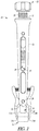
- FIGS. 2 and 2A show the instrument 10 and the pad 12.
- the instrument 10 can include the handle 16, the knob 18, the plunger 20 and the first and second arms 22A and 22B.
- FIG. 2A shows portions of the handle 16 removed to show portions of the knob 18 and the plunger 20 that can be configured to be disposed within a recess 30 that extends along an elongate length of the handle 16 from a proximal end 32 of the handle 16 to a distal end 34 thereof.
- the handle 16 can have openings 36 to view into the recess 30 to visualize the knob 18 and the plunger 20 as well as other components.
- the knob 18 can be configured to couple with the handle 16. More particularly, the knob 18 can be disposed at the proximal end 32 of the handle 16 and can extend into the recess 30.
- the knob 18 can be configured to thread (using threads 36) into the handle 16 (into the recess 30) to move proximal/distal relative to the handle 16.
- the knob 18 can be configured to operatively actuate the plunger 20 to move the plunger 20 proximal/distal within the recess 30 to apply a force on the pad 12.
- FIGS. 2 and 2A show the plunger 20 can be moveably disposed within the recess 30 of the handle 16.
- the plunger 20 can be configured to extend through an opening 38 at the distal end 34 of the handle 16 to engage the pad 12. Such engagement can hold the pad in contact with the femoral component 14 as shown previously in FIG. 1 .
- the first and second arms 22A and 22B can be disposed adjacent the distal end 34 of the handle 16 and can extend further distal of the distal end 34.
- the first and second arms 22A and 22B can be pivotally coupled to the handle 16 via a first pin 39.
- the first and second arms 22A and 22B can be configured as levers to be pivotable relative to one another as well as the handle 16.
- the first and second arms 22A and 22B can each have at least one coupling feature 23A and 23B configured to engage with a corresponding second coupling feature 23AA and 23BB (shown in FIG. 5 ) in the femoral component 14 (refer to FIGS. 5 and 5A ).
- the at least one coupling feature 23A and 23B can comprise a hooked tip 25A and 25B where the first and second arms 22A and 22B can change direction at a distal end portion thereof.
- the change of direction i.e. the hook
- the first and second arms 22A and 22B can each be biased away from the handle 16 by a spring 40A and 40B.
- the spring 40A and 40B can extend between the handle 16 and the first and second arms 22A and 22B, respectively.
- the spring 40A and 40B can be received on a corresponding projection 41A and 41B of the handle 16.
- the spring 40A and 40B can be configured to exert a force on a proximal portion 27A and 27B of the respective first and second arm 22A and 22B. This force can attempt to close the first and second arms 22A and 22B toward one another such that the first and second arms 22A and 22B can act as jaws.
- the force can engage of the first and second arms 22A and 22B with the femoral component 14 (as shown in FIG. 1 ) when the instrument 10 is manipulated and properly placed.
- the force can be overcome by the user pressing on the proximal portion 27A and 27B of the first and second arms 22A and 22B to overcome the force and actuate the first and second arms 22A and 22B away from one another (and out of engagement with the femoral component 14 ( FIG. 1 ).
- the plunger 20 and the knob 18 can include portions internal to the recess 30.
- the knob 18 can include a rod portion 42, a threaded portion 44 (that can include threads 36) and an actuator portion 46.
- the rod portion 42 can include a necked down section 48 and a distal section 50.
- the actuator portion 46 can be configured to extend proximal of the proximal end 32 of the handle 16 and can connect with the threaded portion 44.
- the treaded portion 44 can connect with the rod portion 42.
- the rod portion 42 can be configured to be received within and extend along a longitudinal length of the recess 30.
- the necked down section 48 can be connected to the distal section 50.
- the distal section 50 of the rod portion 42 can have a relatively larger circumference in cross section relative to the necked down section 48.
- a second pin 52 can be disposed within and coupled to the handle 16 (as shown in FIG. 2 ) and can extend inward into the recess 30 to interface with the rod portion 42.
- the second pin 52 can be disposed so as not to make contact with the necked down section 48, thereby allowing for movement of knob 18. However, the second pin 52 can be disposed so as to make contact with the distal section 50. This can keep the knob 18 from being entirely removable from the handle 16 without removal of the second pin 52. Thus, the second pin 52 can be configured to limit at least one of a proximal and distal travel of the knob 18 relative to the handle 16.
- the plunger 20 can include a rod portion 54 and a body portion 56.
- the body portion 56 can include a slot 58 therein.
- the rod portion 54 can include a flange 60.
- the body portion 56 of the plunger 20 can connect with the rod portion 54 and can be disposed distal thereto.
- the rod portion 54 can be received in and can extend along a longitudinal length of the recess 30.
- the body portion 56 can extend from the opening 38 of the recess 30 and can be disposed between the first and second arms 22A and 22B.
- the slot 58 can be disposed in the body portion 56 and can extend longitudinally therealong.
- the slot 58 can be configured to receive the first pin 39 therein.
- the slot 58 can be configured to allow proximal and distal travel of the plunger 20 relative to the handle 16, the first and second arms 22A and 22B and the first pin 39.
- the first flange 60 can extend from the rod portion 54.
- the first flange 60 can be configured to provide a base/stop for one or more springs.
- the one or more springs can comprise a first spring 62 and a second spring 64 according to the example of FIG. 2A .
- the first spring 62 can extend further longitudinally proximal of the second spring 64.
- the first spring 62 can be configured to contact the second pin 52 at a proximal end thereof.
- the first spring 62 can supply a first force to the plunger 20 via the first flange 60.
- the first force can be sufficient to provide for initial engagement between the plunger 20 and the pad 12. However, in some cases the first force may not be sufficiently strong such that the user cannot move the plunger 20 and pad 12 in the proximal direction load the pad 12 between the first and second arm 22A and 22B, for example.
- the second spring 64 can be disposed within the recess 30 between the distal section 50 and the rod portion 54 and can contact the first flange 60 at a distal end thereof.
- the plunger 20 can be coupled to the knob 18 by the second spring 64. More particularly, the second spring 64 can be configured to exert a second force on the plunger 20 when compressed by the knob 18. This second force can be applied when the knob 18 is threaded distally into the handle 16. The second force can be exerted through the plunger 20 to the pad 12 and can provide a further engaging force for rigidly holding the pad 12 to the femoral component.
- the pad 12 can be marked with indicia 70 indicating a posterior and anterior of the pad 12 for engagement against the femoral component.
- the pad 12 can have further indicia such as arrows A ( FIG. 4A ) pointing toward the anterior for reference by the physician.
- the pad 12 can configured to engage a surface of the one or more femoral components along surface 72 and can be engaged by the instrument on an opposing surface 74 (shown in FIG. 4A only).
- the pad 12 can include both a medial notch 76 along a medial side 78 thereof and a lateral notch 80 along a lateral side 82 (both shown in FIG.
- the medial notch 76 and the lateral notch 80 can be configured space a surface 83 of the medial side 78 and a surface 84 of the lateral side 82 of the pad 12 from the first and second arms 22A and 22B as shown in FIG. 4 .
- the medial notch 76 and the lateral notch 80 can provide relief for the pad 12 from engaging the first and second arms 22A and 22B.
- FIGS. 5 and 5A show the femoral component 14 from various perspectives.
- the femoral component 14 can include a bone interfacing surface 90, an articular surface 92, a medial side 94, a lateral side 96, a first notch 98 and a second notch 100.
- the bone interfacing surface 90 can be disposed on an opposing side of the femoral component 14 from the articular surface 92.
- the bone interfacing surface 90 can be configured to seat on and have pegs or other coupling features that can seat in the resected surface of the femur.
- the medial side 94 and the lateral side 96 can separate the bone interfacing surface 90 from the articular surface 92.
- the medial side 94 can be spaced from and opposing the lateral side 96.
- the first notch 98 (shown in both FIGS. 5 and 5A ) can be disposed at the medial side 94 (shown in both FIGS. 5 and 5A ) and the second notch 100 can be spaced therefrom and disposed at the lateral side 96.
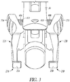
- the first and second notches 98, 100 can be recessed from the articular surface 92 and the bone interfacing surface 90. Each of the first and second notch 98, 100 can define an opening 102, 104 along the respective medial side 94 and lateral side 96. Each of the first and second notch 98, 100 can be configured to receive one of the respective hooked tips 25A, 25B ( FIG. 3 ) therein via the respective opening 102, 104.
Landscapes
- Health & Medical Sciences (AREA)
- Orthopedic Medicine & Surgery (AREA)
- Transplantation (AREA)
- Life Sciences & Earth Sciences (AREA)
- Engineering & Computer Science (AREA)
- General Health & Medical Sciences (AREA)
- Biomedical Technology (AREA)
- Heart & Thoracic Surgery (AREA)
- Veterinary Medicine (AREA)
- Public Health (AREA)
- Animal Behavior & Ethology (AREA)
- Oral & Maxillofacial Surgery (AREA)
- Physical Education & Sports Medicine (AREA)
- Cardiology (AREA)
- Vascular Medicine (AREA)
- Surgery (AREA)
- Molecular Biology (AREA)
- Medical Informatics (AREA)
- Nuclear Medicine, Radiotherapy & Molecular Imaging (AREA)
- Prostheses (AREA)
- Surgical Instruments (AREA)
Claims (7)
- System, das eine Femurkomponente (14) und ein Instrument (10) zum mindesten einen von Anbringen und Entfernen der Femurkomponente (14) an einem Femur umfasst, wobei das Instrument umfasst:einen Griff (16), der eine Aussparung darin definiert, wobei sich die Aussparung entlang eines Abschnitts einer länglichen Länge des Griffs erstreckt;einen Kolben (20), der beweglich in der Aussparung angeordnet ist und konfiguriert ist, um sich durch eine Öffnung in einem distalen Ende des Griffs zu erstrecken, um in eine Auflage (12) einzugreifen, um die Auflage in Kontakt mit der Femurkomponente zu halten;einen ersten und einen zweiten Arm (22A, 22B), die schwenkbar mit dem Griff (16) gekoppelt und relativ zueinander schwenkbar sind, wobei der erste und der zweite Arm jeweils mindestens ein Kopplungsmerkmal aufweisen, das konfiguriert ist, um mit einem entsprechenden zweiten Kopplungsmerkmal in der Femurkomponente (14) in Eingriff zu sein; undeinen Knopf (18), der konfiguriert ist, um den Kolben (20) betriebsmäßig zu betätigen, um den Kolben proximal/distal in der Aussparung zu bewegen, um eine Kraft auf die Auflage (12) auszuüben, dadurch gekennzeichnet, dass das Instrument einen Stift (39) umfasst, der den Griff (16) schwenkbar mit dem ersten und zweiten Arm (22A, 22B) koppelt, wobei der Kolben (20) einen Schlitz (30) umfasst, der konfiguriert ist, um den Stift (39) aufzunehmen,und wobei der Schlitz (30) konfiguriert ist, um eine proximale und distale Bewegung des Kolbens (20) relativ zu dem Griff (16), dem ersten und dem zweiten Arm (22A, 22B) und dem Stift (39) zu ermöglichen,wobei das Instrument ferner einen zweiten Stift (52) umfasst, der mit dem Griff (16) gekoppelt ist, wobei der zweite Stift (52) konfiguriert ist, um mindestens einen von einem proximalen und distalen Weg des Knopfes (18) relativ zum Griff (16) zu begrenzen.
- System nach Anspruch 1, wobei das mindestens eine Kopplungsmerkmal eine hakenförmige Spitze (25A, 25B) umfasst und das zweite Kopplungsmerkmal eine Kerbe (98, 100) umfasst, die konfiguriert ist, um die hakenförmige Spitze darin aufzunehmen.
- System nach einem der Ansprüche 1 oder 2, wobei der erste und der zweite Arm jeweils durch eine Feder (40A, 40B) vom Griff weg vorgespannt sind, wobei die Feder eine Kraft ausübt, die versucht, den ersten und den zweiten Arm zueinander zu schließen.
- System nach einem der Ansprüche 1 bis 3, wobei der Kolben durch eine zweite Feder (64) mit dem Knopf gekoppelt ist, wobei die zweite Feder in der Aussparung angeordnet ist und die zweite Feder konfiguriert ist, um eine Kraft auf den Kolben auszuüben, wenn sie durch den Knopf zusammengedrückt wird.
- System nach einem der Ansprüche 1 bis 4, wobei der Knopf an einem proximalen Ende des Griffs angeordnet ist und konfiguriert ist, um in den Griff zu schrauben, um sich relativ dazu proximal/distal zu bewegen.
- System nach einem der Ansprüche 2 bis 5, ferner umfassend eine oder mehrere Auflagen (12), die konfiguriert sind, um in eine Oberfläche der Femurkomponente (14) einzugreifen und von dem Instrument (10) in Eingriff gebracht zu werden, wobei die eine oder mehreren Auflagen sowohl eine mediale Kerbe (76) entlang einer medialen Seite (78) davon als auch eine laterale Kerbe (80) entlang einer lateralen Seite (82) davon umfassen, wobei die mediale Kerbe und die laterale Kerbe der einen oder mehreren Auflagen konfigurierter Abstand eine erste Oberfläche (83) der medialen Seite (78) und eine zweite Oberfläche (84) der lateralen Seite (82) der einen oder mehreren Auflagen vom ersten bzw. zweiten Arm (22A, 22B) sind.
- System nach einem der Ansprüche 1 bis 6, umfassend eine Familie von Femurkomponenten, die sich jeweils in Größe voneinander unterscheiden.
Applications Claiming Priority (2)
| Application Number | Priority Date | Filing Date | Title |
|---|---|---|---|
| US201662408257P | 2016-10-14 | 2016-10-14 | |
| PCT/US2017/056141 WO2018071543A1 (en) | 2016-10-14 | 2017-10-11 | Femoral inserter and retractor |
Publications (2)
| Publication Number | Publication Date |
|---|---|
| EP3525728A1 EP3525728A1 (de) | 2019-08-21 |
| EP3525728B1 true EP3525728B1 (de) | 2021-04-21 |
Family
ID=60190952
Family Applications (1)
| Application Number | Title | Priority Date | Filing Date |
|---|---|---|---|
| EP17791521.2A Active EP3525728B1 (de) | 2016-10-14 | 2017-10-11 | Femurinserter und retraktor |
Country Status (3)
| Country | Link |
|---|---|
| US (1) | US10842647B2 (de) |
| EP (1) | EP3525728B1 (de) |
| WO (1) | WO2018071543A1 (de) |
Families Citing this family (4)
| Publication number | Priority date | Publication date | Assignee | Title |
|---|---|---|---|---|
| WO2018071543A1 (en) | 2016-10-14 | 2018-04-19 | Zimmer, Inc. | Femoral inserter and retractor |
| US11399961B2 (en) * | 2019-01-15 | 2022-08-02 | Shukla Medical | Implant extractor tool |
| CN113349994A (zh) * | 2021-06-10 | 2021-09-07 | 北京力达康科技有限公司 | 一种股骨髁假体夹持器 |
| CN116549187B (zh) * | 2023-05-04 | 2026-02-17 | 北京市春立正达医疗器械股份有限公司 | 一种单髁股骨髁把持器 |
Family Cites Families (10)
| Publication number | Priority date | Publication date | Assignee | Title |
|---|---|---|---|---|
| JPH07507946A (ja) * | 1992-06-17 | 1995-09-07 | ミネソタ・マイニング・アンド・マニュファクチュアリング・カンパニー | 人工ひざ関節移植片のために大腿骨を準備し,該移植片の大腿骨構成要素を位置決めするための器具使用 |
| US5732992A (en) | 1996-12-26 | 1998-03-31 | Exactech, Incorporated | Medical appliance tool providing one hand actuation |
| DE10013331A1 (de) | 2000-03-09 | 2001-09-20 | Biomet Merck Deutschland Gmbh | Haltevorrichtung |
| US7879042B2 (en) * | 2004-03-05 | 2011-02-01 | Depuy Products, Inc. | Surface replacement extractor device and associated method |
| US20060149284A1 (en) * | 2004-12-15 | 2006-07-06 | Sdgi Holdings, Inc. | Insertion device and method for inserting a member within the body |
| NZ548878A (en) * | 2006-08-01 | 2008-11-28 | Enztec Ltd | Improved impactor |
| US9220611B2 (en) | 2011-07-12 | 2015-12-29 | Zimmer, Inc. | Femoral component instrument |
| US9925066B2 (en) * | 2013-08-13 | 2018-03-27 | Arthrex, Inc. | Surgical impactor/extractor assembly and method of use |
| US9782877B2 (en) * | 2015-03-11 | 2017-10-10 | Robert Paul Marquis | Panel fastener tool for quickly, safely, and easily removing and inserting panel fasteners |
| WO2018071543A1 (en) | 2016-10-14 | 2018-04-19 | Zimmer, Inc. | Femoral inserter and retractor |
-
2017
- 2017-10-11 WO PCT/US2017/056141 patent/WO2018071543A1/en not_active Ceased
- 2017-10-11 US US15/730,276 patent/US10842647B2/en active Active
- 2017-10-11 EP EP17791521.2A patent/EP3525728B1/de active Active
Non-Patent Citations (1)
| Title |
|---|
| None * |
Also Published As
| Publication number | Publication date |
|---|---|
| US20180104070A1 (en) | 2018-04-19 |
| US10842647B2 (en) | 2020-11-24 |
| EP3525728A1 (de) | 2019-08-21 |
| WO2018071543A1 (en) | 2018-04-19 |
Similar Documents
| Publication | Publication Date | Title |
|---|---|---|
| RU2744481C2 (ru) | Система и способ подготовки бедренной кости пациента при проведении ортопедической операции по эндопротезированию сустава | |
| US11413165B2 (en) | Bearing trial system | |
| US20070282451A1 (en) | Prosthesis and implementation system | |
| EP3525692B1 (de) | Multifunktionswerkzeug | |
| EP2777635B1 (de) | Chirurgisches Instrument | |
| EP3525728B1 (de) | Femurinserter und retraktor | |
| CN112220589A (zh) | 股骨试件部件和相关联的矫形外科使用方法 | |
| EP4410222A2 (de) | Tibiaschnittführung | |
| EP3355834A1 (de) | Tibiaprothese für tibia mit varusresektion | |
| US11571224B2 (en) | Tibial cut guide | |
| CN114305813A (zh) | 整形外科器械系统和试验整形外科假体组件的方法 | |
| HK1223812A1 (zh) | 反转膝部假体 | |
| US20170209278A1 (en) | Methods and techniques for tibial implant placement |
Legal Events
| Date | Code | Title | Description |
|---|---|---|---|
| STAA | Information on the status of an ep patent application or granted ep patent |
Free format text: STATUS: UNKNOWN |
|
| STAA | Information on the status of an ep patent application or granted ep patent |
Free format text: STATUS: THE INTERNATIONAL PUBLICATION HAS BEEN MADE |
|
| PUAI | Public reference made under article 153(3) epc to a published international application that has entered the european phase |
Free format text: ORIGINAL CODE: 0009012 |
|
| STAA | Information on the status of an ep patent application or granted ep patent |
Free format text: STATUS: REQUEST FOR EXAMINATION WAS MADE |
|
| 17P | Request for examination filed |
Effective date: 20190514 |
|
| AK | Designated contracting states |
Kind code of ref document: A1 Designated state(s): AL AT BE BG CH CY CZ DE DK EE ES FI FR GB GR HR HU IE IS IT LI LT LU LV MC MK MT NL NO PL PT RO RS SE SI SK SM TR |
|
| AX | Request for extension of the european patent |
Extension state: BA ME |
|
| DAV | Request for validation of the european patent (deleted) | ||
| DAX | Request for extension of the european patent (deleted) | ||
| STAA | Information on the status of an ep patent application or granted ep patent |
Free format text: STATUS: EXAMINATION IS IN PROGRESS |
|
| 17Q | First examination report despatched |
Effective date: 20200423 |
|
| GRAP | Despatch of communication of intention to grant a patent |
Free format text: ORIGINAL CODE: EPIDOSNIGR1 |
|
| STAA | Information on the status of an ep patent application or granted ep patent |
Free format text: STATUS: GRANT OF PATENT IS INTENDED |
|
| INTG | Intention to grant announced |
Effective date: 20201102 |
|
| RIN1 | Information on inventor provided before grant (corrected) |
Inventor name: VANDIEPENBOS, JEFFERY A. Inventor name: JONES, NOLAN C. |
|
| GRAS | Grant fee paid |
Free format text: ORIGINAL CODE: EPIDOSNIGR3 |
|
| GRAA | (expected) grant |
Free format text: ORIGINAL CODE: 0009210 |
|
| STAA | Information on the status of an ep patent application or granted ep patent |
Free format text: STATUS: THE PATENT HAS BEEN GRANTED |
|
| AK | Designated contracting states |
Kind code of ref document: B1 Designated state(s): AL AT BE BG CH CY CZ DE DK EE ES FI FR GB GR HR HU IE IS IT LI LT LU LV MC MK MT NL NO PL PT RO RS SE SI SK SM TR |
|
| REG | Reference to a national code |
Ref country code: GB Ref legal event code: FG4D |
|
| REG | Reference to a national code |
Ref country code: CH Ref legal event code: EP Ref country code: CH Ref legal event code: NV Representative=s name: MICHELI AND CIE SA, CH |
|
| REG | Reference to a national code |
Ref country code: DE Ref legal event code: R096 Ref document number: 602017037209 Country of ref document: DE Ref country code: IE Ref legal event code: FG4D |
|
| REG | Reference to a national code |
Ref country code: AT Ref legal event code: REF Ref document number: 1383849 Country of ref document: AT Kind code of ref document: T Effective date: 20210515 |
|
| REG | Reference to a national code |
Ref country code: LT Ref legal event code: MG9D |
|
| REG | Reference to a national code |
Ref country code: AT Ref legal event code: MK05 Ref document number: 1383849 Country of ref document: AT Kind code of ref document: T Effective date: 20210421 |
|
| REG | Reference to a national code |
Ref country code: NL Ref legal event code: MP Effective date: 20210421 |
|
| PG25 | Lapsed in a contracting state [announced via postgrant information from national office to epo] |
Ref country code: HR Free format text: LAPSE BECAUSE OF FAILURE TO SUBMIT A TRANSLATION OF THE DESCRIPTION OR TO PAY THE FEE WITHIN THE PRESCRIBED TIME-LIMIT Effective date: 20210421 Ref country code: AT Free format text: LAPSE BECAUSE OF FAILURE TO SUBMIT A TRANSLATION OF THE DESCRIPTION OR TO PAY THE FEE WITHIN THE PRESCRIBED TIME-LIMIT Effective date: 20210421 Ref country code: BG Free format text: LAPSE BECAUSE OF FAILURE TO SUBMIT A TRANSLATION OF THE DESCRIPTION OR TO PAY THE FEE WITHIN THE PRESCRIBED TIME-LIMIT Effective date: 20210721 Ref country code: NL Free format text: LAPSE BECAUSE OF FAILURE TO SUBMIT A TRANSLATION OF THE DESCRIPTION OR TO PAY THE FEE WITHIN THE PRESCRIBED TIME-LIMIT Effective date: 20210421 Ref country code: FI Free format text: LAPSE BECAUSE OF FAILURE TO SUBMIT A TRANSLATION OF THE DESCRIPTION OR TO PAY THE FEE WITHIN THE PRESCRIBED TIME-LIMIT Effective date: 20210421 Ref country code: LT Free format text: LAPSE BECAUSE OF FAILURE TO SUBMIT A TRANSLATION OF THE DESCRIPTION OR TO PAY THE FEE WITHIN THE PRESCRIBED TIME-LIMIT Effective date: 20210421 |
|
| PG25 | Lapsed in a contracting state [announced via postgrant information from national office to epo] |
Ref country code: IS Free format text: LAPSE BECAUSE OF FAILURE TO SUBMIT A TRANSLATION OF THE DESCRIPTION OR TO PAY THE FEE WITHIN THE PRESCRIBED TIME-LIMIT Effective date: 20210821 Ref country code: GR Free format text: LAPSE BECAUSE OF FAILURE TO SUBMIT A TRANSLATION OF THE DESCRIPTION OR TO PAY THE FEE WITHIN THE PRESCRIBED TIME-LIMIT Effective date: 20210722 Ref country code: SE Free format text: LAPSE BECAUSE OF FAILURE TO SUBMIT A TRANSLATION OF THE DESCRIPTION OR TO PAY THE FEE WITHIN THE PRESCRIBED TIME-LIMIT Effective date: 20210421 Ref country code: RS Free format text: LAPSE BECAUSE OF FAILURE TO SUBMIT A TRANSLATION OF THE DESCRIPTION OR TO PAY THE FEE WITHIN THE PRESCRIBED TIME-LIMIT Effective date: 20210421 Ref country code: LV Free format text: LAPSE BECAUSE OF FAILURE TO SUBMIT A TRANSLATION OF THE DESCRIPTION OR TO PAY THE FEE WITHIN THE PRESCRIBED TIME-LIMIT Effective date: 20210421 Ref country code: PT Free format text: LAPSE BECAUSE OF FAILURE TO SUBMIT A TRANSLATION OF THE DESCRIPTION OR TO PAY THE FEE WITHIN THE PRESCRIBED TIME-LIMIT Effective date: 20210823 Ref country code: NO Free format text: LAPSE BECAUSE OF FAILURE TO SUBMIT A TRANSLATION OF THE DESCRIPTION OR TO PAY THE FEE WITHIN THE PRESCRIBED TIME-LIMIT Effective date: 20210721 Ref country code: PL Free format text: LAPSE BECAUSE OF FAILURE TO SUBMIT A TRANSLATION OF THE DESCRIPTION OR TO PAY THE FEE WITHIN THE PRESCRIBED TIME-LIMIT Effective date: 20210421 |
|
| REG | Reference to a national code |
Ref country code: DE Ref legal event code: R097 Ref document number: 602017037209 Country of ref document: DE |
|
| PG25 | Lapsed in a contracting state [announced via postgrant information from national office to epo] |
Ref country code: SK Free format text: LAPSE BECAUSE OF FAILURE TO SUBMIT A TRANSLATION OF THE DESCRIPTION OR TO PAY THE FEE WITHIN THE PRESCRIBED TIME-LIMIT Effective date: 20210421 Ref country code: SM Free format text: LAPSE BECAUSE OF FAILURE TO SUBMIT A TRANSLATION OF THE DESCRIPTION OR TO PAY THE FEE WITHIN THE PRESCRIBED TIME-LIMIT Effective date: 20210421 Ref country code: DK Free format text: LAPSE BECAUSE OF FAILURE TO SUBMIT A TRANSLATION OF THE DESCRIPTION OR TO PAY THE FEE WITHIN THE PRESCRIBED TIME-LIMIT Effective date: 20210421 Ref country code: EE Free format text: LAPSE BECAUSE OF FAILURE TO SUBMIT A TRANSLATION OF THE DESCRIPTION OR TO PAY THE FEE WITHIN THE PRESCRIBED TIME-LIMIT Effective date: 20210421 Ref country code: CZ Free format text: LAPSE BECAUSE OF FAILURE TO SUBMIT A TRANSLATION OF THE DESCRIPTION OR TO PAY THE FEE WITHIN THE PRESCRIBED TIME-LIMIT Effective date: 20210421 Ref country code: RO Free format text: LAPSE BECAUSE OF FAILURE TO SUBMIT A TRANSLATION OF THE DESCRIPTION OR TO PAY THE FEE WITHIN THE PRESCRIBED TIME-LIMIT Effective date: 20210421 Ref country code: ES Free format text: LAPSE BECAUSE OF FAILURE TO SUBMIT A TRANSLATION OF THE DESCRIPTION OR TO PAY THE FEE WITHIN THE PRESCRIBED TIME-LIMIT Effective date: 20210421 |
|
| PLBE | No opposition filed within time limit |
Free format text: ORIGINAL CODE: 0009261 |
|
| STAA | Information on the status of an ep patent application or granted ep patent |
Free format text: STATUS: NO OPPOSITION FILED WITHIN TIME LIMIT |
|
| 26N | No opposition filed |
Effective date: 20220124 |
|
| PG25 | Lapsed in a contracting state [announced via postgrant information from national office to epo] |
Ref country code: IS Free format text: LAPSE BECAUSE OF FAILURE TO SUBMIT A TRANSLATION OF THE DESCRIPTION OR TO PAY THE FEE WITHIN THE PRESCRIBED TIME-LIMIT Effective date: 20210821 Ref country code: AL Free format text: LAPSE BECAUSE OF FAILURE TO SUBMIT A TRANSLATION OF THE DESCRIPTION OR TO PAY THE FEE WITHIN THE PRESCRIBED TIME-LIMIT Effective date: 20210421 |
|
| REG | Reference to a national code |
Ref country code: BE Ref legal event code: MM Effective date: 20211031 |
|
| PG25 | Lapsed in a contracting state [announced via postgrant information from national office to epo] |
Ref country code: MC Free format text: LAPSE BECAUSE OF FAILURE TO SUBMIT A TRANSLATION OF THE DESCRIPTION OR TO PAY THE FEE WITHIN THE PRESCRIBED TIME-LIMIT Effective date: 20210421 |
|
| PG25 | Lapsed in a contracting state [announced via postgrant information from national office to epo] |
Ref country code: LU Free format text: LAPSE BECAUSE OF NON-PAYMENT OF DUE FEES Effective date: 20211011 Ref country code: IT Free format text: LAPSE BECAUSE OF FAILURE TO SUBMIT A TRANSLATION OF THE DESCRIPTION OR TO PAY THE FEE WITHIN THE PRESCRIBED TIME-LIMIT Effective date: 20210421 Ref country code: BE Free format text: LAPSE BECAUSE OF NON-PAYMENT OF DUE FEES Effective date: 20211031 |
|
| PG25 | Lapsed in a contracting state [announced via postgrant information from national office to epo] |
Ref country code: IE Free format text: LAPSE BECAUSE OF NON-PAYMENT OF DUE FEES Effective date: 20211011 |
|
| PG25 | Lapsed in a contracting state [announced via postgrant information from national office to epo] |
Ref country code: CY Free format text: LAPSE BECAUSE OF FAILURE TO SUBMIT A TRANSLATION OF THE DESCRIPTION OR TO PAY THE FEE WITHIN THE PRESCRIBED TIME-LIMIT Effective date: 20210421 |
|
| P01 | Opt-out of the competence of the unified patent court (upc) registered |
Effective date: 20230525 |
|
| PG25 | Lapsed in a contracting state [announced via postgrant information from national office to epo] |
Ref country code: HU Free format text: LAPSE BECAUSE OF FAILURE TO SUBMIT A TRANSLATION OF THE DESCRIPTION OR TO PAY THE FEE WITHIN THE PRESCRIBED TIME-LIMIT; INVALID AB INITIO Effective date: 20171011 |
|
| PG25 | Lapsed in a contracting state [announced via postgrant information from national office to epo] |
Ref country code: MK Free format text: LAPSE BECAUSE OF FAILURE TO SUBMIT A TRANSLATION OF THE DESCRIPTION OR TO PAY THE FEE WITHIN THE PRESCRIBED TIME-LIMIT Effective date: 20210421 |
|
| PG25 | Lapsed in a contracting state [announced via postgrant information from national office to epo] |
Ref country code: TR Free format text: LAPSE BECAUSE OF FAILURE TO SUBMIT A TRANSLATION OF THE DESCRIPTION OR TO PAY THE FEE WITHIN THE PRESCRIBED TIME-LIMIT Effective date: 20210421 |
|
| PG25 | Lapsed in a contracting state [announced via postgrant information from national office to epo] |
Ref country code: MT Free format text: LAPSE BECAUSE OF FAILURE TO SUBMIT A TRANSLATION OF THE DESCRIPTION OR TO PAY THE FEE WITHIN THE PRESCRIBED TIME-LIMIT Effective date: 20210421 |
|
| REG | Reference to a national code |
Ref country code: CH Ref legal event code: U11 Free format text: ST27 STATUS EVENT CODE: U-0-0-U10-U11 (AS PROVIDED BY THE NATIONAL OFFICE) Effective date: 20251101 |
|
| PGFP | Annual fee paid to national office [announced via postgrant information from national office to epo] |
Ref country code: DE Payment date: 20251010 Year of fee payment: 9 |
|
| PGFP | Annual fee paid to national office [announced via postgrant information from national office to epo] |
Ref country code: GB Payment date: 20251013 Year of fee payment: 9 |
|
| PGFP | Annual fee paid to national office [announced via postgrant information from national office to epo] |
Ref country code: FR Payment date: 20251014 Year of fee payment: 9 |
|
| PGFP | Annual fee paid to national office [announced via postgrant information from national office to epo] |
Ref country code: CH Payment date: 20251101 Year of fee payment: 9 |