EP3525890B1 - Procédé de commande de l'alimentation en gaz respiratoire - Google Patents
Procédé de commande de l'alimentation en gaz respiratoire Download PDFInfo
- Publication number
- EP3525890B1 EP3525890B1 EP17797746.9A EP17797746A EP3525890B1 EP 3525890 B1 EP3525890 B1 EP 3525890B1 EP 17797746 A EP17797746 A EP 17797746A EP 3525890 B1 EP3525890 B1 EP 3525890B1
- Authority
- EP
- European Patent Office
- Prior art keywords
- mass flow
- valve
- pressure
- flow
- altitude
- Prior art date
- Legal status (The legal status is an assumption and is not a legal conclusion. Google has not performed a legal analysis and makes no representation as to the accuracy of the status listed.)
- Active
Links
Images




Classifications
-
- A—HUMAN NECESSITIES
- A62—LIFE-SAVING; FIRE-FIGHTING
- A62B—DEVICES, APPARATUS OR METHODS FOR LIFE-SAVING
- A62B7/00—Respiratory apparatus
- A62B7/14—Respiratory apparatus for high-altitude aircraft
Definitions
- the present disclosure relates to a method for controlling the breathing gas supply to one or more breathing masks of an emergency oxygen supply device, as well as to a device for the emergency supply of oxygen for carrying out this method.
- a pressurized cabin in which a cabin pressure ensuring the oxygen supply to the passengers amid an adequate supply of fresh air is envisaged with today's common jet aircraft which have a cruising altitude of 10,000 m and more.
- Emergency oxygen supply systems with which the passengers can also be supplied with an adequate quantity of oxygen when a case of decompression arises, thus a drop in the cabin pressure, are provided in order to be able to ensure the supply of oxygen to the passengers given such an unexpected sudden pressure drop at such an altitude.
- Such systems typically include either pressurized oxygen containers or chemical oxygen generators which lead the breathing gas or oxygen via a conduit system to the breathing masks envisaged for the supply of the passengers, in an adequate quantity.
- the emergency oxygen system is to be designed such that an adequate oxygen supply to the passengers is ensured at the maximal flight altitude to be expected.
- the oxygen requirement reduces with a falling altitude, since the oxygen share in the surrounding air increases.
- the quantity of oxygen or breathing gas which is to be carried along as low as possible since it is indeed the carrying-along of oxygen, be it in pressurized containers or in generators, which entails a significant weight which must be borne by the aircraft and reduces the payload capacity.
- the quantity of oxygen or breathing gas which is dispensed to the breathing masks is controlled in a manner dependent on cabin pressure according to pertinent regulations.
- the cabin pressure largely corresponds to the surrounding air pressure which is essentially dependent on the altitude of the aircraft.
- the oxygen quantity which is to be fed to the passengers is a function of the cabin pressure which is a function of the altitude, is stipulated in the pertinent regulations. Thereby, one constantly strives not only to bring the oxygen quantity as close as possible to the minimum-prescribed value, in order to maintain the oxygen consumption as low as possible, but also to design technical devices which are employed as lightweight and inexpensive as possible manner.
- EP 2004294 B1 entitled “A Respiratory Gas Supply Circuit for an Aircraft Carrying Passengers” it is counted as belonging to the state of the art, to control the oxygen supply to the breathing masks and which is dependent on the cabin pressure, which is to say dependent on altitude, by way of an on/off valve.
- the control of the oxygen quantity is effected using pulse width modulation of the on/off valve.
- such a method is characterised by the characterising features of claim 1.
- the at least one valve is a magnetic valve.
- the actuation of the at least one valve includes supplying a triggering voltage to the at least one valve.
- the minimal error is between 10% and 50% of the desired mass flow and the maximal error is between 10% and 100% of the desired mass flow.
- US 2015/0290481 discloses a system according to the preamble of claim 4. According to a second aspect of the present invention, such a system is characterised by the characterising features of claim 4.
- the oxygen source is an oxygen storage device, breathing gas storage device, or an oxygen generator.
- the system further includes a pressure sensor and the desired mass flow is determined based on a signal from the pressure sensor.
- controlling the opening and closing of the valve as a function of the desired mass flow and the actual mass flow includes determining a minimal error value and a maximal error value; causing actuation of the valve to a closed position when a difference between the actual flow and the desired flow exceeds the maximal error value; and causing actuation of the valve to an open position when a difference between the desired flow and the actual flow exceeds the minimal error value.
- an emergency supply of oxygen is provided to crew and passengers of an aircraft, from compressed oxygen storage containers, or as a result of a chemical reaction between two or more reagents.
- the aircraft When the aircraft reaches 10,000 feet the passengers can safely breathe atmospheric air and the emergency supply of oxygen may be stopped. Many land masses extend above 10,000 feet and thus, the aircraft may not descend to 10,000 feet, an alternative yet safe flight profile is possible in which upon decompression the aircraft descends to a safe holding altitude, which would be above, 10,000 feet, and preferably around 25,000 feet, while the passengers and crew are supplied with oxygen enriched gas.
- an emergency oxygen supply device is provided according to one example.
- a pressure-leading conduit 1 for oxygen which is fed by an oxygen stored device, a compressed gas bottle, or an oxygen producer is connected via a valve 2 (e.g., magnetic latching valve such as a bistable magnet on/off valve) to a group of breathing masks 3, of which here two are shown by way of example.
- the valve 2 is configured to block or release a conduit connection.
- the valve provides energy savings since only one switching impulse is produced for switching over the valve. In particular, no further energy is to be supplied, particularly in the opened position, as is otherwise the case with simple magnet valves.
- the valve may include a permanent magnet and a coil.
- the latching valve is stable in either shifted state due to the permanent magnet.
- the valve 2 may stay in either state indefinitely without drawing power.
- a negative pulse e.g., to the coil
- the valve changes from an open to a closed position.
- the valve is energized with a positive pulse
- the valve changes from a closed position to an open position.
- the valve 2 is connected to breathing masks 3 via the conduit.
- the breathing masks 3 are passenger oxygen masks common in civilian air travel as would be understood by one of ordinary skill in the art.
- the breathing masks 3, for example, may be provided with a breathing bag 4 arranged upstream as would be understood by one of ordinary skill in the art.
- the breathing bag 4 represents a buffer for the oxygen supply.
- the breathing mask 4 is provided with an auxiliary air valve.
- the number of the breathing masks is preferably two to six breathing masks connected to the pressure-leading conduit.
- a flow mass meter 5 is provided in the conduit to the breathing masks 3, at the exit side of the valve 2.
- the flow mass meter 5, for example, can include a mass flow sensor, a volume sensor, or in another suitable manner as would be understood by one of ordinary skill in the art.
- the flow mass meter 5, for example, is configured to detect or estimate the actual mass flow of oxygen to the breathing masks 3.
- the actual mass flow measurement is effected continuously or in sufficiently short intervals, for example between one millisecond to 100 ms.
- a control and regulation unit 7 which controls the magnet valve 2 as a function of both cabin pressure and flow mass to the breathing masks 3.
- a signal or measurement from the flow mass meter 5, for example, may be supplied to the control and regulation unit 7.
- the control and regulation unit 7 may adjust setpoints (e.g., desired mass flow, minimal and maximal error values) for maximized mass flow. Thus, a minimum oxygen flow is provided even in a failure case.
- a pressure sensor 6 is provided, which detects the cabin pressure within the aircraft.
- the pressure sensor 6 may be remotely located, such as within a central control system.
- the pressure sensor 6 may be connected to one or more control and regulation units.
- a pressure sensor provided in a main cabin control unit may supply a cabin pressure measurement to the control and regulation unit 7.
- the pressure sensor 6 may be one of the pressure sensors available in the aircraft, its value being available upon connection to the aircraft communications bus.
- a dedicated pressure sensor 6 is provided with the control and regulation unit 7.
- each control and regulation unit 7 may be provided with its own pressure sensor.
- the control and regulation unit 7 may obtain a cabin pressure measurement from a central control system, for example via a central communications bus of the aircraft.
- an altimeter signal or measurement is supplied to the control and regulation unit 7, for example, via an altimeter 25.
- the altimeter measurement for example, may be provided by the central aircraft control via the central communications bus.
- the altimeter signal or measurement may identify a current elevation of travel of the aircraft.
- the control and regulation unit 7 includes a first computation unit 8, a second computation unit 9, and a third computation unit 10.
- the units described herein may be implemented as either software and/or hardware modules and may be stored in any type of computer-readable medium or other computer storage device.
- each of the units described herein may be implemented in circuitry that is programmable (e.g. microprocessor-based circuits) or dedicated circuits such as application specific integrated circuits (ASICS) or field programmable gate arrays (FPGAS).
- a central processing unit (CPU) could execute software to perform the functions attributable to each of the units described herein.
- the CPU may execute software instructions written in a programing language such as Java, C, or assembly.
- One or more software instructions in the modules may be embedded in firmware, such as an erasable programmable read-only memory (EPROM).
- EPROM erasable programmable read-only memory
- the control and regulation unit 7 is formed by a microprocessor.
- the first computation unit 8 determines a desired mass flow based on the cabin pressure.
- the desired mass flow is the flow associated with the cabin pressure, in order to supply the connected breathing masks 3 or the persons connected thereto, with the required quantity of oxygen.
- the desired mass flow in some examples, may be determined using values stored in a tabular form, in a curve, or an algorithm.
- the first computation unit may apply the cabin pressure determined via the pressure sensor 6 to a look-up table to determine the desired mass flow. Since the cabin pressure represents the flight altitude and the oxygen of the surrounding air which results from the flight altitude, in some embodiments, an altimeter reading may be used in addition to or in lieu of the cabin pressure measurement. For example, in the event of failure of the cabin pressure sensor 6, the first computation unit 8 may receive an altimeter reading for determining the desired mass flow.
- the second computation unit 9 determines the desired values (set points) and error values for closed-loop control, as a function of the desired mass flow determined by the first computation unit 8. The mass flow over time is summed in the third computation unit 10 as a function the signal detected by the flow mass meter 5, and the current or actual error value to the desired mass flow is determined.
- the second computation unit 9 receives input from the altimeter 25 for tracking cruising altitude over time to more accurately determine set points and error values.
- the cabin pressure may be fed to the second computation unit 9 from the pressure sensor 6 for use in estimating cruising altitude over time. For example, when a fault is detected in the pressure sensor 6 (e.g., when the measurements are out of range), the second computation unit 9 may determine the desired values based on values received from the altimeter 25.
- a maximal and minimal error value are set, in some embodiments, in the third computation unit 10.
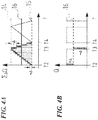
- the third computation unit 10 may send a signal to actuate the valve 2. That is, the valve 2 receives a switching impulse for change-over when either the maximal or minimal error value is reached. Determination of maximal and minimal error values is described in greater detail below in relation to FIGS. 3A-C and FIGS. 4A and 4B .
- control and regulation unit 7 is connected to one valve 2.
- the number of valves in an aircraft for example, is in part a function of the number of breathing masks that may be connected to the valve 2 while maintaining adequate pressure for oxygen delivery to the breathing masks 3.
- the number of masks supplied by each valve for example, is a function of the maximum oxygen flow of the valve 2. For example, in a large aircraft (e.g., 300 passengers) and assuming three masks are connected to each valve, then a total of one hundred control and regulation units may be used. In other embodiments, fewer control and regulation units may be used, with each control and regulation unit controlling a number of valves presented in parallel, each valve supplying oxygen to a particular bank of breathing masks.
- the control and regulation unit 7 may control two or more magnet valves by individually calculating and outputting the desired values to the two or more valves.
- Curve 700 shows the flow as a function of the cabin altitude. Curve 700 may be stored in the second computation unit 9.
- the flow of oxygen per minute is a function of the mask performance.
- the maximum flow rate may be 3.1 L/min at an altitude of 40,000 feet. The flow rate decreases with the altitude.
- the flow rate at the holding altitude may be 1L/min.
- FIG. 2 is a schematic that shows the desired mass flow as a function of the cabin pressure, which is to say in dependence on the flight altitude or the surrounding pressure.
- Curve 11 may be stored in the first computation unit 8.
- a likewise pressure-dependent maximal error is shown by curve 12 and is represented with respect to curve 11.
- a minimal error is shown by curve 13 and is represented below the curve 11.
- the curves 12 and 13, as FIG. 2 clearly shows, in their course follow the curve 11 which represents the desired mass flow in dependence on the cabin pressure, but are shifted by a certain amount to the top (curve 12) or to the bottom (curve 13), thus mark the error band or tolerance band around the curve 11.
- These curves 12 and 13 are stored in the computation unit 10.
- FIGS. 3A-C and FIG. 4A and B The control of the valve 2 is represented in FIGS. 3A-C and FIG. 4A and B .
- a maximal error value 14 is derived from the curve 12 and a minimal error value 15 is derived from the curve 13, in FIGS. 3A and 4A respectively.
- Curve 16 in FIGS. 3B and 4B represents the desired mass flow.
- the maximal error value is preferably set between 10% and 100% above the desired mass flow. The greater the maximal error, the lower is the number of switching cycles.
- the minimal error value preferably lies between 10% and 50% below the desired mass flow. The switching frequency of the valve drops with an increasing minimal error value.
- the error values are selected such that with regard to the temporal average, the actual mass flow corresponds at least to the desired mass flow or is preferably slightly greater, in order to ensure an adequate oxygen supply to the passengers under all circumstances.
- the error values are selected such that after the first cycle, the actual mass flow corresponds to the desired mass flow or is larger than the desired mass flow.
- the valve 2 is activated to open firstly at the point in time t0.
- oxygen flows through the conduit 1 and the opened valve 2 to the breathing masks 3.
- the quantity of the oxygen flowing through is detected via the flow mass sensor 5, and the error value resulting with respect to the desired mass flow is temporally summed in the third computation unit 10.
- the summing is represented in FIGS. 3A and 4A .
- an undersupply is to be ascertained, until, with an opened valve 2, the actual mass flow flowing through the valve has exceeded the desired mass flow and has reached the maximal error value 14.
- the valve 2 is changed-over by way of a switching impulse 17, whereupon it is closed and thus no further oxygen flows to the breathing masks 3.
- FIG. 3B shows the desired values at two altitudes.
- a first desired value (setpoint) 16a is associated with a first altitude.
- a second desired value 16b is associated with a second altitude lower than the first altitude.
- the first desired value 16a represents a higher flow than the second desired value 16b.
- FIG. 3B shows, on one hand the switching procedures per se are comparatively low, since the valve 2 is merely switched over on reaching a maximum or minimum error, but no high-frequency activation of the valve is necessary, as is common with pulse width modulation.
- the activation is moreover significantly better adapted to the actual oxygen requirement, since the method is not limited to a frequency and a sampling degree, as is necessary with pulse width modulation.
- flows 23, 24 of FIG. 3B show example mass flow at a higher input pressure, therefore the oxygen flow is higher.
- the upper error value 14 is reached faster and the valve is switched off faster as shown by switching pulses 21 and 22.
- the previously described closed-loop control method sums the errors of the control variable for the control of the valve 2.
- the error value is summed into a desired value (setpoint) which is determined in a pressure-dependent manner in the first computation unit 8 of FIG. 1 by way of predefined values. If the error sum reaches the upper error value 14 given an opened valve 2, then the valve 2 is reversed. Only when the error sum reaches the lower defined error value 15 ( FIG. 3A ) is the valve again switched over and thus opened. Thus it is always only one energy impulse is required for the switching, not for the holding of the opened valve, as can be clearly recognized by way of FIG. 3C which diagrams both positive and negative voltage impulses actuating the valve 2 to accomplish the flow profile of FIG. 3B .
- FIG. 5 is a flowchart illustrating a method 500 to control breathing gas supply when a decompression arises according to an example.
- the method 500 may be performed by the control and regulation unit 7 described in relation to FIG. 1 .
- the method 500 in a particular example, may be used to effect the flow profile illustrated in FIG. 3B .
- the method 500 begins with determining the desired mass flow to initiate oxygen flow (502).
- the desired mass flow may be based on the cabin pressure.
- a predefined value may be used.
- the predefined value may be the desired mass flow associated with an altitude of 35,000 feet.
- the predefined value may also be determined based on the typical cruising altitude of the aircraft (e.g., based on the flight route) or the aircraft type (e.g., maximum flying altitude of the aircraft).
- an altimeter reading may be used to estimate cabin pressure based upon a current cruising altitude.
- the desired mass flow in one example, is set by the first computation unit 8 of FIG. 1 .
- a first maximal error (e.g., 50% above the desired mass flow) and a first minimal error (e.g., 10 % below the desired mass flow) may be set (504).
- the first maximal error and the second maximal error may be determined based on the desired mass flow.
- the second computation unit 9 of FIG. 1 may set the first maximal error and the first minimal error.
- a valve disposed between an oxygen source and a number of oxygen masks is actuated to an open position to begin oxygen flow to the oxygen masks (506).
- the valve for example, may be a magnetic valve actuated through a voltage impulse.
- the trigger mechanism causing the valve to actuate to the open position for example, may be effected by the third computational unit 10 of FIG. 1 .
- a difference between an actual mass flow measurement and the desired mass flow is determined (508). The determination may be effected by the third computation unit 10 of FIG. 1 .
- the actual mass flow measurement is an average of a series of mass flow measurements taken over time, for example to avoid making decisions based upon anomalous or inaccurate measurements. Further, in some embodiments, one or more inaccurate readings (e.g., outside a reasonable or reliable range of measurements) may be discarded in determining the actual mass flow measurement.
- the difference between the actual mass flow and the desired mass flow may be compared to the maximal error to determine whether the reading is within tolerance.
- the valve if the difference between the actual and desired mass flow exceeds the maximal error (510), the valve is actuated to a closed position to stop oxygen flow to the oxygen masks (512).
- the trigger mechanism causing the valve to actuate to the closed position may be effected by the third computational unit 10 of FIG. 1 .
- a difference between an actual mass flow measurement and the desired mass flow is determined (514).
- the determination for example, may be effected by the third computation unit 10 of FIG. 1 .
- the determination may be effected by the first computation unit 8 of FIG. 1 based on measurement received from the pressure sensor 6 of FIG. 1 .
- the determination may be effected based on the flight altitude.
- the flight altitude may be determined by the altimeter 25 of FIG. 1 .
- a look-up table may be referenced to determine a cabin pressure associated with the flight altitude.
- the method 500 may end. For example, at a cruising altitude of 10,000 feet, oxygen levels within the cabin may be adequate without supply of oxygen through the breathing masks.
- the determination may be effected by the second computation unit 9 based on received altitude measurements.
- the altitude measurement for example, may be provided by the altimeter 25 of FIG. 1 .
- a new desired mass flow is determined (524).
- the new desired mass flow may be effected by the first computation unit 8 of FIG. 1 .
- a look-up table may be referenced to determine the desired mass flow based on a change in the flight altitude.
- the minimal error and maximal error are updated based upon the updated desired mass flow (524).
- the updated maximal error and the updated minimal error may be determined based on the new desired mass flow.
- the second computation unit 9 of FIG. 1 may set the updated maximal error and the updated minimal error.
- the method 500 based upon the minimal error being reached (516), whether or not the cabin pressure has changed (520), as long as the cruising altitude has not yet reached a safe altitude (522), the method 500 returns to actuating the valve to an open position (506) and monitoring the mass flow (508, 510). The mass flow will be monitored, in the circumstance that the cabin pressure and/or altitude changed, based upon the updated desired mass flow (524).
- the method 500 may be performed in a different order.
- the cruising altitude may be monitored for a safe altitude (522) on an ongoing and/or periodic basis not connected with whether or not the cabin pressure has changed and/or the valve has actuated to the closed position.
- the desired mass flow may be updated (524) prior to actuating the valve to the closed position (512), based upon, for example, a change in cabin pressure and/or cruising altitude.
- the first maximal and minimal error values may be determined (504) before determining the desired mass flow (502).
- the first maximal and minimal error values may be determined (504) independently from the desired mass flow (502) and the cabin pressure.
- the first maximal and minimal error values may be predefined values.
- the maximal and minimal error values may not be updated upon the updated desired mass flow (524).
- more or fewer steps may be included in the method 500.
- a predefined holding altitude e.g., 25,000 feet
- the desired mass flow is set to the mass flow associated with the predefined holding altitude. For example, a 6,000 feet/minute rapid descent may be assumed and the predetermined period may be set to 5 minutes.
- the methods and systems according to the present disclosure is thus not to modulate the sampling degree of the rectangular impulse, thus the width of the impulse, at a constant frequency, as with the state of the art, but to firstly activate the valve in an opening manner until the error between the actual mass flow and the pressure-dependently set desired mass flow and which is summed over time exceeds a previously fixed maximum error value. That is, to hold the valve open for so long until more oxygen has been supplied to the breathing mask or breathing masks, than this would be necessary in a manner dependent on cabin pressure.
- the methods and systems may be based on volume values (detected by volumetric flow detection). For example, an actual volume flow and a desired volume flow.
- the methods and systems described herein can also be used without any problem if the desired mass flow changes, if for example the aircraft is in descent, since then the maximal and the minimal error value according to the curves 12 and 13 are adapted, and due to the summing of the error values, it is always ensured that the desired mass flow is also achieved.
- This closed-loop control is largely insensitive to disturbance parameters and avoids the inherent problems of a PID closed loop control as is typically applied with the state of the art.
- valve downstream of the valve 2 ( FIG. 1 ) and to dimension the valve downstream (e.g., nozzle, orifice) in a manner such that a supersonic flow, i.e. overcritical flow, with which the flow quantity is essentially proportional to the pressure prevailing at the nozzle, sets in with the expected operating range.
- a pressure sensor is advantageously arranged between the on/off valve and the nozzle.
- the actual mass flow is determined as a function of the temporal course of the pressure.
- the pressure in front of the nozzle is essentially proportional to the mass flow, i.e. the mass stream through the nozzle, so that the mass flow to the passenger oxygen masks can be determined by way of the pressure.
- the pressure metering run may include a pressure transducer 600 and an orifice 602.
- the pressure metering run is positioned at the exit side of the valve 2.
- the performance of the orifice meter system is a function of the precision of the orifice (or nozzle) and the accuracy of the pressure transducer. At low flow rates, the errors in the pressure transducer measurement can lead to a large error in the actual flow rates. For this reason, two or more pressure metering runs are provided.
- the multiple pressure metering runs are operated in parallel. In this example, when the total flow is great all pressure metering runs are operated and the flow rates are summed to yield a total flow measurement. When the total flow rate decreases, individual pressure metering runs may be disabled, resulting in increased flow rates through the remaining pressure metering runs. Each pressure metering run may be controlled using a switch 604.
- the control and regulation unit 7 may activate/deactivate the pressure metering runs as a function of the altitude.
- the orifices 602a, 602b, 602c in some embodiments, have equal diameter. In other embodiments, each of the orifices may be of different diameter. In one embodiment, the diameter of the first orifice 26a may be associated with a mass flow associated with a first altitude range and the second orifice 26b may be associated with a mass flow associated with a second altitude range.
- the control and regulation may activate switch 604a or 604b based on the current altitude.
- the orifice may be a simple orifice to constrain the oxygen enriched gas to flow, or may include a variable orifice the cross section of which may be varied according to operating conditions, by for example, the control and regulation unit 7.
- two or more differential pressure transducers may be used in parallel for each orifice.
- Each of the two or more differential pressure transducers may be configured for a different flow rate (i.e., one for low flow, another for high flow).
- the method described herein can reduce the switching frequency of the on/off valve in comparison to known methods.
- valves with lower switching reliability can be employed, or with the same switching reliability ensures an increased safety from failure.
Landscapes
- Health & Medical Sciences (AREA)
- Pulmonology (AREA)
- General Health & Medical Sciences (AREA)
- Business, Economics & Management (AREA)
- Emergency Management (AREA)
- Respiratory Apparatuses And Protective Means (AREA)
Claims (7)
- Procédé de commande d'une alimentation en gaz respiratoire d'une pluralité de masques respiratoires (3) dans un aéronef de passagers, le procédé comprenant les étapes consistant à :déterminer, par des circuits de traitement (7), un débit massique souhaité, une erreur maximale, et une erreur minimale ;provoquer, par les circuits de traitement, l'actionnement d'au moins une soupape (2) vers une position ouverte ; etcommander, par les circuits de traitement, le débit massique de l'alimentation en gaz respiratoire de la pluralité de masques respiratoires (3), où la commande comprenda) la surveillance d'un débit massique réel d'alimentation en gaz respiratoire de la pluralité de masques respiratoires par des mesures obtenues à partir d'un appareil de mesure de débit massique (5),b) la détermination du fait que le débit massique réel dépasse le débit massique souhaité d'au moins l'erreur maximale,c) en réponse à la détermination du fait que le débit massique réel dépasse le débit massique souhaité, la provocation de l'actionnement de l'au moins une soupape (2) vers une position fermée,d) la poursuite de la surveillance du débit massique réel,e) la détermination du fait que le débit massique souhaité dépasse le débit massique réel d'au moins l'erreur minimale,f) en réponse à la détermination du fait que le débit massique souhaité dépasse le débit massique réel, le fait de provoquer l'actionnement de l'au moins une soupape (2) vers une position ouverte, et la répétition des étapes (a) à (f) ;dans lequel la commande du débit massique de l'alimentation en gaz respiratoire de la pluralité de masques respiratoires (3) comprend en outre :la surveillance d'au moins l'une d'une pression de cabine et d'une altitude de l'aéronef de passagers ; et la mise à jour, sur la base d'un changement d'au moins l'une de la pression de cabine et de l'altitude, d'un ou de plusieurs de l'erreur minimale, de l'erreur maximale, et du débit massique souhaité ;caractérisé en ce que l'appareil de mesure de débit massique (5) comprend une pluralité de sections de mesure de pression agencées en aval de la soupape, chaque section de mesure de pression comportant une buse, et un transducteur de pression (600), les mesures obtenues à partir de l'appareil de mesure de débit massique comprennent des signaux produits par les transducteurs de pression (600) ;en ce que la commande du débit massique de l'alimentation en gaz respiratoire de la pluralité de masques respiratoires comprend en outre la commande d'un commutateur respectif (604) d'au moins une section de mesure de pression de la pluralité de sections de mesure de pression sur la base d'au moins l'un d'une pression de cabine, d'une altitude de l'aéronef de passagers, et du débit massique souhaité ; eten ce que la commande du commutateur respectif (604) comprend l'activation d'au moins deux sections de mesure de pression de la pluralité de sections de mesure de pression en parallèle.
- Procédé selon la revendication 1, dans lequel l'au moins une soupape (2) est une soupape magnétique, et le fait de provoquer l'actionnement de l'au moins une soupape comprend l'alimentation de l'au moins une soupape en tension de déclenchement.
- Procédé selon la revendication 1, dans lequel l'erreur minimale est comprise entre 10 % et 50 % du débit massique souhaité et l'erreur maximale est comprise entre 10 % et 100 % du débit massique souhaité.
- Système de commande d'une alimentation en oxygène d'urgence dans un aéronef de passagers, le système comprenant :une soupape (2) disposée entre une source d'oxygène et une pluralité de masques respiratoires (3) ;un moyen (5) pour mesurer le débit massique disposé entre la soupape et la pluralité de masques respiratoires ; etdes circuits de traitement (7) configurés pour déterminer un débit massique souhaité, surveiller au fil du temps un débit massique réel sur la base des mesures fournies par le moyen de mesure du débit massique, etcommander l'ouverture et la fermeture de la soupape (2), lors de la surveillance, en fonction du débit massique souhaité et du débit massique réel ;dans lequel les circuits de commande sont configurés pour commander le débit massique de l'alimentation en gaz respiratoire de la pluralité de masques respiratoires (3) en surveillant au moins l'une d'une pression de cabine et d'une altitude de l'aéronef de passagers ; et en mettant à jour, sur la base d'un changement d'au moins l'une de la pression de cabine et de l'altitude, un ou plusieurs de l'erreur minimale, de l'erreur maximale, et du débit massique souhaité ; caractérisé en ce que le moyen de mesure du débit massique comprend un moyen de production d'un écoulement supersonique et un transducteur de pression ;en ce que le moyen de mesure du débit massique comprend une pluralité de sections de mesure de pression agencées en aval de la soupape, chaque section de mesure de pression comportant un moyen de production d'un écoulement supersonique et un transducteur de pression ;en ce que les circuits de traitement sont configurés pour actionner au moins un commutateur (604) pour activer et désactiver au moins une section de mesure de pression de la pluralité de sections de mesure de pression ; eten ce que les circuits de traitement sont configurés pour déterminer, avant d'actionner l'au moins un commutateur, au moins l'un d'un changement de pression de cabine et d'un changement d'altitude, où une position de l'au moins un commutateur est sélectionnée sur la base de l'au moins un changement parmi le changement de pression de cabine et le changement d'altitude.
- Système selon la revendication 4, dans lequel la source d'oxygène est un dispositif de stockage d'oxygène, un dispositif de stockage de gaz respiratoire, ou un générateur d'oxygène.
- Système selon la revendication 4, comprenant en outre :un capteur de pression ; etdans lequel le débit massique souhaité est déterminé sur la base d'un signal provenant du capteur de pression.
- Système selon la revendication 4, dans lequel la commande de l'ouverture et de la fermeture de la soupape en fonction du débit massique souhaité et du débit massique réel comprend :la détermination d'une valeur d'erreur minimale et d'une valeur d'erreur maximale ;le fait de provoquer l'actionnement de la soupape vers une position fermée lorsqu'une différence entre le débit réel et le débit souhaité dépasse la valeur d'erreur maximale ; etle fait de provoquer l'actionnement de la soupape vers une position ouverte lorsqu'une différence entre le débit souhaité et le débit réel dépasse la valeur d'erreur minimale.
Applications Claiming Priority (2)
| Application Number | Priority Date | Filing Date | Title |
|---|---|---|---|
| US15/294,144 US10709910B2 (en) | 2014-04-09 | 2016-10-14 | Method for the control of the breathing gas supply |
| PCT/IB2017/056382 WO2018069895A1 (fr) | 2016-10-14 | 2017-10-13 | Procédé de commande de l'alimentation en gaz respiratoire |
Publications (2)
| Publication Number | Publication Date |
|---|---|
| EP3525890A1 EP3525890A1 (fr) | 2019-08-21 |
| EP3525890B1 true EP3525890B1 (fr) | 2021-09-22 |
Family
ID=60320933
Family Applications (1)
| Application Number | Title | Priority Date | Filing Date |
|---|---|---|---|
| EP17797746.9A Active EP3525890B1 (fr) | 2016-10-14 | 2017-10-13 | Procédé de commande de l'alimentation en gaz respiratoire |
Country Status (2)
| Country | Link |
|---|---|
| EP (1) | EP3525890B1 (fr) |
| WO (1) | WO2018069895A1 (fr) |
Family Cites Families (4)
| Publication number | Priority date | Publication date | Assignee | Title |
|---|---|---|---|---|
| EP2004294B1 (fr) | 2006-04-13 | 2010-07-21 | Intertechnique | Circuit d'alimentation en gaz respiratoire destine a un avion transportant des passagers |
| EP2143469A1 (fr) * | 2008-07-11 | 2010-01-13 | Intertechnique SA | Dispositif respiratoire à oxygène doté d'un mesurage du débit de masse |
| DE102014206878B4 (de) * | 2014-04-09 | 2016-11-10 | B/E Aerospace Systems Gmbh | Verfahren zum Steuern der Atemgaszufuhr |
| CN105999577B (zh) * | 2016-07-22 | 2019-03-08 | 中国航空工业集团公司西安飞机设计研究所 | 一种氧源控制方法 |
-
2017
- 2017-10-13 WO PCT/IB2017/056382 patent/WO2018069895A1/fr not_active Ceased
- 2017-10-13 EP EP17797746.9A patent/EP3525890B1/fr active Active
Also Published As
| Publication number | Publication date |
|---|---|
| WO2018069895A1 (fr) | 2018-04-19 |
| EP3525890A1 (fr) | 2019-08-21 |
Similar Documents
| Publication | Publication Date | Title |
|---|---|---|
| US11738216B2 (en) | Method for the control of the breathing gas supply | |
| US10213630B2 (en) | Method for the control of the breathing gas supply | |
| EP2901227B1 (fr) | Procédé et appareil permettant une vérification automatique de la pression sur la base de dispositifs de régulation du débit massique | |
| US9119977B2 (en) | Oxygen breathing device with mass flow control | |
| AU2009262847B2 (en) | System for regulating the dispensing of commercial aircraft passenger emergency oxygen supply | |
| US20190282839A1 (en) | System and a method for delivering breathing gas to passengers on-board an aircraft | |
| EP3533495B1 (fr) | Systèmes d'oxygène dosés présentant des caractéristiques antiblocage de tubes de distribution et procédé de distribution de gaz respiratoire | |
| EP2004294B1 (fr) | Circuit d'alimentation en gaz respiratoire destine a un avion transportant des passagers | |
| EP2143469A1 (fr) | Dispositif respiratoire à oxygène doté d'un mesurage du débit de masse | |
| CN110244780A (zh) | 用于实时监测穿过质量流量控制器的流量的系统以及方法 | |
| US8463496B2 (en) | Decoupling control architecture for pressure and flow controls in series | |
| EP2703282B1 (fr) | Système et procédé permettant d'égaliser une surpression à l'intérieur d'une cabine d'aéronef | |
| EP3525890B1 (fr) | Procédé de commande de l'alimentation en gaz respiratoire | |
| GB2439839A (en) | Cockpit oxygen mask with magnetic valve | |
| US7950987B2 (en) | Aircraft cabin pressure control system and method that improves cabin pressurization during take-off | |
| US6688308B1 (en) | Method of testing an aircraft oxygen supply system | |
| US11883694B2 (en) | Phase dilution demand oxygen regulator (PDDOR) system for personal breathing | |
| RU2581893C1 (ru) | Способ регулирования давления воздуха в герметической кабине летательного аппарата и устройство для его осуществления | |
| WO2008010015A1 (fr) | Circuit d'alimentation en gaz respiratoire destiné à fournir de l'oxygène aux membres d'équipage et aux passagers | |
| RU89486U1 (ru) | Регулятор параметра среды | |
| FI62954B (fi) | Apparat foer artificiell ventilering av lungor | |
| RU2581892C1 (ru) | Способ регулирования давления воздуха в герметической кабине при ее разгерметизации и устройство для его осуществления | |
| RU46370U1 (ru) | Регулятор давления газа |
Legal Events
| Date | Code | Title | Description |
|---|---|---|---|
| STAA | Information on the status of an ep patent application or granted ep patent |
Free format text: STATUS: UNKNOWN |
|
| STAA | Information on the status of an ep patent application or granted ep patent |
Free format text: STATUS: THE INTERNATIONAL PUBLICATION HAS BEEN MADE |
|
| PUAI | Public reference made under article 153(3) epc to a published international application that has entered the european phase |
Free format text: ORIGINAL CODE: 0009012 |
|
| STAA | Information on the status of an ep patent application or granted ep patent |
Free format text: STATUS: REQUEST FOR EXAMINATION WAS MADE |
|
| 17P | Request for examination filed |
Effective date: 20190513 |
|
| AK | Designated contracting states |
Kind code of ref document: A1 Designated state(s): AL AT BE BG CH CY CZ DE DK EE ES FI FR GB GR HR HU IE IS IT LI LT LU LV MC MK MT NL NO PL PT RO RS SE SI SK SM TR |
|
| AX | Request for extension of the european patent |
Extension state: BA ME |
|
| DAV | Request for validation of the european patent (deleted) | ||
| DAX | Request for extension of the european patent (deleted) | ||
| STAA | Information on the status of an ep patent application or granted ep patent |
Free format text: STATUS: EXAMINATION IS IN PROGRESS |
|
| 17Q | First examination report despatched |
Effective date: 20200806 |
|
| GRAP | Despatch of communication of intention to grant a patent |
Free format text: ORIGINAL CODE: EPIDOSNIGR1 |
|
| STAA | Information on the status of an ep patent application or granted ep patent |
Free format text: STATUS: GRANT OF PATENT IS INTENDED |
|
| INTG | Intention to grant announced |
Effective date: 20210408 |
|
| GRAS | Grant fee paid |
Free format text: ORIGINAL CODE: EPIDOSNIGR3 |
|
| GRAA | (expected) grant |
Free format text: ORIGINAL CODE: 0009210 |
|
| STAA | Information on the status of an ep patent application or granted ep patent |
Free format text: STATUS: THE PATENT HAS BEEN GRANTED |
|
| AK | Designated contracting states |
Kind code of ref document: B1 Designated state(s): AL AT BE BG CH CY CZ DE DK EE ES FI FR GB GR HR HU IE IS IT LI LT LU LV MC MK MT NL NO PL PT RO RS SE SI SK SM TR |
|
| REG | Reference to a national code |
Ref country code: GB Ref legal event code: FG4D |
|
| REG | Reference to a national code |
Ref country code: DE Ref legal event code: R096 Ref document number: 602017046455 Country of ref document: DE |
|
| REG | Reference to a national code |
Ref country code: IE Ref legal event code: FG4D |
|
| REG | Reference to a national code |
Ref country code: CH Ref legal event code: EP Ref country code: AT Ref legal event code: REF Ref document number: 1431846 Country of ref document: AT Kind code of ref document: T Effective date: 20211015 |
|
| REG | Reference to a national code |
Ref country code: LT Ref legal event code: MG9D |
|
| REG | Reference to a national code |
Ref country code: NL Ref legal event code: MP Effective date: 20210922 |
|
| PG25 | Lapsed in a contracting state [announced via postgrant information from national office to epo] |
Ref country code: LT Free format text: LAPSE BECAUSE OF FAILURE TO SUBMIT A TRANSLATION OF THE DESCRIPTION OR TO PAY THE FEE WITHIN THE PRESCRIBED TIME-LIMIT Effective date: 20210922 Ref country code: BG Free format text: LAPSE BECAUSE OF FAILURE TO SUBMIT A TRANSLATION OF THE DESCRIPTION OR TO PAY THE FEE WITHIN THE PRESCRIBED TIME-LIMIT Effective date: 20211222 Ref country code: NO Free format text: LAPSE BECAUSE OF FAILURE TO SUBMIT A TRANSLATION OF THE DESCRIPTION OR TO PAY THE FEE WITHIN THE PRESCRIBED TIME-LIMIT Effective date: 20211222 Ref country code: RS Free format text: LAPSE BECAUSE OF FAILURE TO SUBMIT A TRANSLATION OF THE DESCRIPTION OR TO PAY THE FEE WITHIN THE PRESCRIBED TIME-LIMIT Effective date: 20210922 Ref country code: SE Free format text: LAPSE BECAUSE OF FAILURE TO SUBMIT A TRANSLATION OF THE DESCRIPTION OR TO PAY THE FEE WITHIN THE PRESCRIBED TIME-LIMIT Effective date: 20210922 Ref country code: HR Free format text: LAPSE BECAUSE OF FAILURE TO SUBMIT A TRANSLATION OF THE DESCRIPTION OR TO PAY THE FEE WITHIN THE PRESCRIBED TIME-LIMIT Effective date: 20210922 Ref country code: FI Free format text: LAPSE BECAUSE OF FAILURE TO SUBMIT A TRANSLATION OF THE DESCRIPTION OR TO PAY THE FEE WITHIN THE PRESCRIBED TIME-LIMIT Effective date: 20210922 |
|
| REG | Reference to a national code |
Ref country code: AT Ref legal event code: MK05 Ref document number: 1431846 Country of ref document: AT Kind code of ref document: T Effective date: 20210922 |
|
| PG25 | Lapsed in a contracting state [announced via postgrant information from national office to epo] |
Ref country code: LV Free format text: LAPSE BECAUSE OF FAILURE TO SUBMIT A TRANSLATION OF THE DESCRIPTION OR TO PAY THE FEE WITHIN THE PRESCRIBED TIME-LIMIT Effective date: 20210922 Ref country code: GR Free format text: LAPSE BECAUSE OF FAILURE TO SUBMIT A TRANSLATION OF THE DESCRIPTION OR TO PAY THE FEE WITHIN THE PRESCRIBED TIME-LIMIT Effective date: 20211223 |
|
| PG25 | Lapsed in a contracting state [announced via postgrant information from national office to epo] |
Ref country code: AT Free format text: LAPSE BECAUSE OF FAILURE TO SUBMIT A TRANSLATION OF THE DESCRIPTION OR TO PAY THE FEE WITHIN THE PRESCRIBED TIME-LIMIT Effective date: 20210922 |
|
| REG | Reference to a national code |
Ref country code: CH Ref legal event code: PL |
|
| PG25 | Lapsed in a contracting state [announced via postgrant information from national office to epo] |
Ref country code: IS Free format text: LAPSE BECAUSE OF FAILURE TO SUBMIT A TRANSLATION OF THE DESCRIPTION OR TO PAY THE FEE WITHIN THE PRESCRIBED TIME-LIMIT Effective date: 20220122 Ref country code: SK Free format text: LAPSE BECAUSE OF FAILURE TO SUBMIT A TRANSLATION OF THE DESCRIPTION OR TO PAY THE FEE WITHIN THE PRESCRIBED TIME-LIMIT Effective date: 20210922 Ref country code: RO Free format text: LAPSE BECAUSE OF FAILURE TO SUBMIT A TRANSLATION OF THE DESCRIPTION OR TO PAY THE FEE WITHIN THE PRESCRIBED TIME-LIMIT Effective date: 20210922 Ref country code: PT Free format text: LAPSE BECAUSE OF FAILURE TO SUBMIT A TRANSLATION OF THE DESCRIPTION OR TO PAY THE FEE WITHIN THE PRESCRIBED TIME-LIMIT Effective date: 20220124 Ref country code: PL Free format text: LAPSE BECAUSE OF FAILURE TO SUBMIT A TRANSLATION OF THE DESCRIPTION OR TO PAY THE FEE WITHIN THE PRESCRIBED TIME-LIMIT Effective date: 20210922 Ref country code: NL Free format text: LAPSE BECAUSE OF FAILURE TO SUBMIT A TRANSLATION OF THE DESCRIPTION OR TO PAY THE FEE WITHIN THE PRESCRIBED TIME-LIMIT Effective date: 20210922 Ref country code: ES Free format text: LAPSE BECAUSE OF FAILURE TO SUBMIT A TRANSLATION OF THE DESCRIPTION OR TO PAY THE FEE WITHIN THE PRESCRIBED TIME-LIMIT Effective date: 20210922 Ref country code: EE Free format text: LAPSE BECAUSE OF FAILURE TO SUBMIT A TRANSLATION OF THE DESCRIPTION OR TO PAY THE FEE WITHIN THE PRESCRIBED TIME-LIMIT Effective date: 20210922 Ref country code: CZ Free format text: LAPSE BECAUSE OF FAILURE TO SUBMIT A TRANSLATION OF THE DESCRIPTION OR TO PAY THE FEE WITHIN THE PRESCRIBED TIME-LIMIT Effective date: 20210922 Ref country code: AL Free format text: LAPSE BECAUSE OF FAILURE TO SUBMIT A TRANSLATION OF THE DESCRIPTION OR TO PAY THE FEE WITHIN THE PRESCRIBED TIME-LIMIT Effective date: 20210922 |
|
| REG | Reference to a national code |
Ref country code: DE Ref legal event code: R097 Ref document number: 602017046455 Country of ref document: DE Ref country code: BE Ref legal event code: MM Effective date: 20211031 |
|
| PG25 | Lapsed in a contracting state [announced via postgrant information from national office to epo] |
Ref country code: MC Free format text: LAPSE BECAUSE OF FAILURE TO SUBMIT A TRANSLATION OF THE DESCRIPTION OR TO PAY THE FEE WITHIN THE PRESCRIBED TIME-LIMIT Effective date: 20210922 |
|
| PG25 | Lapsed in a contracting state [announced via postgrant information from national office to epo] |
Ref country code: LU Free format text: LAPSE BECAUSE OF NON-PAYMENT OF DUE FEES Effective date: 20211013 Ref country code: DK Free format text: LAPSE BECAUSE OF FAILURE TO SUBMIT A TRANSLATION OF THE DESCRIPTION OR TO PAY THE FEE WITHIN THE PRESCRIBED TIME-LIMIT Effective date: 20210922 Ref country code: BE Free format text: LAPSE BECAUSE OF NON-PAYMENT OF DUE FEES Effective date: 20211031 |
|
| PLBE | No opposition filed within time limit |
Free format text: ORIGINAL CODE: 0009261 |
|
| STAA | Information on the status of an ep patent application or granted ep patent |
Free format text: STATUS: NO OPPOSITION FILED WITHIN TIME LIMIT |
|
| 26N | No opposition filed |
Effective date: 20220623 |
|
| PG25 | Lapsed in a contracting state [announced via postgrant information from national office to epo] |
Ref country code: LI Free format text: LAPSE BECAUSE OF NON-PAYMENT OF DUE FEES Effective date: 20211031 Ref country code: CH Free format text: LAPSE BECAUSE OF NON-PAYMENT OF DUE FEES Effective date: 20211031 |
|
| PG25 | Lapsed in a contracting state [announced via postgrant information from national office to epo] |
Ref country code: IE Free format text: LAPSE BECAUSE OF NON-PAYMENT OF DUE FEES Effective date: 20211013 |
|
| PG25 | Lapsed in a contracting state [announced via postgrant information from national office to epo] |
Ref country code: SI Free format text: LAPSE BECAUSE OF FAILURE TO SUBMIT A TRANSLATION OF THE DESCRIPTION OR TO PAY THE FEE WITHIN THE PRESCRIBED TIME-LIMIT Effective date: 20210922 |
|
| PG25 | Lapsed in a contracting state [announced via postgrant information from national office to epo] |
Ref country code: IT Free format text: LAPSE BECAUSE OF FAILURE TO SUBMIT A TRANSLATION OF THE DESCRIPTION OR TO PAY THE FEE WITHIN THE PRESCRIBED TIME-LIMIT Effective date: 20210922 |
|
| PG25 | Lapsed in a contracting state [announced via postgrant information from national office to epo] |
Ref country code: CY Free format text: LAPSE BECAUSE OF FAILURE TO SUBMIT A TRANSLATION OF THE DESCRIPTION OR TO PAY THE FEE WITHIN THE PRESCRIBED TIME-LIMIT Effective date: 20210922 |
|
| PG25 | Lapsed in a contracting state [announced via postgrant information from national office to epo] |
Ref country code: SM Free format text: LAPSE BECAUSE OF FAILURE TO SUBMIT A TRANSLATION OF THE DESCRIPTION OR TO PAY THE FEE WITHIN THE PRESCRIBED TIME-LIMIT Effective date: 20210922 Ref country code: HU Free format text: LAPSE BECAUSE OF FAILURE TO SUBMIT A TRANSLATION OF THE DESCRIPTION OR TO PAY THE FEE WITHIN THE PRESCRIBED TIME-LIMIT; INVALID AB INITIO Effective date: 20171013 |
|
| P01 | Opt-out of the competence of the unified patent court (upc) registered |
Effective date: 20230630 |
|
| PG25 | Lapsed in a contracting state [announced via postgrant information from national office to epo] |
Ref country code: MK Free format text: LAPSE BECAUSE OF FAILURE TO SUBMIT A TRANSLATION OF THE DESCRIPTION OR TO PAY THE FEE WITHIN THE PRESCRIBED TIME-LIMIT Effective date: 20210922 |
|
| PG25 | Lapsed in a contracting state [announced via postgrant information from national office to epo] |
Ref country code: TR Free format text: LAPSE BECAUSE OF FAILURE TO SUBMIT A TRANSLATION OF THE DESCRIPTION OR TO PAY THE FEE WITHIN THE PRESCRIBED TIME-LIMIT Effective date: 20210922 |
|
| PG25 | Lapsed in a contracting state [announced via postgrant information from national office to epo] |
Ref country code: MT Free format text: LAPSE BECAUSE OF FAILURE TO SUBMIT A TRANSLATION OF THE DESCRIPTION OR TO PAY THE FEE WITHIN THE PRESCRIBED TIME-LIMIT Effective date: 20210922 |
|
| PGFP | Annual fee paid to national office [announced via postgrant information from national office to epo] |
Ref country code: GB Payment date: 20250923 Year of fee payment: 9 |
|
| PGFP | Annual fee paid to national office [announced via postgrant information from national office to epo] |
Ref country code: FR Payment date: 20250924 Year of fee payment: 9 |
|
| PGFP | Annual fee paid to national office [announced via postgrant information from national office to epo] |
Ref country code: DE Payment date: 20250923 Year of fee payment: 9 |