EP3525985B1 - Agencement de sécurité et procédé pour une machine à surfacer les sols - Google Patents
Agencement de sécurité et procédé pour une machine à surfacer les sols Download PDFInfo
- Publication number
- EP3525985B1 EP3525985B1 EP17862867.3A EP17862867A EP3525985B1 EP 3525985 B1 EP3525985 B1 EP 3525985B1 EP 17862867 A EP17862867 A EP 17862867A EP 3525985 B1 EP3525985 B1 EP 3525985B1
- Authority
- EP
- European Patent Office
- Prior art keywords
- surfacing
- motor
- floor
- machine
- drive wheel
- Prior art date
- Legal status (The legal status is an assumption and is not a legal conclusion. Google has not performed a legal analysis and makes no representation as to the accuracy of the status listed.)
- Active
Links
Images


Classifications
-
- A—HUMAN NECESSITIES
- A47—FURNITURE; DOMESTIC ARTICLES OR APPLIANCES; COFFEE MILLS; SPICE MILLS; SUCTION CLEANERS IN GENERAL
- A47L—DOMESTIC WASHING OR CLEANING; SUCTION CLEANERS IN GENERAL
- A47L11/00—Machines for cleaning floors, carpets, furniture, walls, or wall coverings
- A47L11/40—Parts or details of machines not provided for in groups A47L11/02 - A47L11/38, or not restricted to one of these groups, e.g. handles, arrangements of switches, skirts, buffers, levers
- A47L11/4011—Regulation of the cleaning machine by electric means; Control systems and remote control systems therefor
-
- B—PERFORMING OPERATIONS; TRANSPORTING
- B24—GRINDING; POLISHING
- B24B—MACHINES, DEVICES, OR PROCESSES FOR GRINDING OR POLISHING; DRESSING OR CONDITIONING OF ABRADING SURFACES; FEEDING OF GRINDING, POLISHING, OR LAPPING AGENTS
- B24B55/00—Safety devices for grinding or polishing machines; Accessories fitted to grinding or polishing machines for keeping tools or parts of the machine in good working condition
-
- A—HUMAN NECESSITIES
- A47—FURNITURE; DOMESTIC ARTICLES OR APPLIANCES; COFFEE MILLS; SPICE MILLS; SUCTION CLEANERS IN GENERAL
- A47L—DOMESTIC WASHING OR CLEANING; SUCTION CLEANERS IN GENERAL
- A47L11/00—Machines for cleaning floors, carpets, furniture, walls, or wall coverings
- A47L11/02—Floor surfacing or polishing machines
- A47L11/10—Floor surfacing or polishing machines motor-driven
- A47L11/14—Floor surfacing or polishing machines motor-driven with rotating tools
- A47L11/16—Floor surfacing or polishing machines motor-driven with rotating tools the tools being disc brushes
-
- A—HUMAN NECESSITIES
- A47—FURNITURE; DOMESTIC ARTICLES OR APPLIANCES; COFFEE MILLS; SPICE MILLS; SUCTION CLEANERS IN GENERAL
- A47L—DOMESTIC WASHING OR CLEANING; SUCTION CLEANERS IN GENERAL
- A47L11/00—Machines for cleaning floors, carpets, furniture, walls, or wall coverings
- A47L11/02—Floor surfacing or polishing machines
- A47L11/10—Floor surfacing or polishing machines motor-driven
- A47L11/14—Floor surfacing or polishing machines motor-driven with rotating tools
-
- A—HUMAN NECESSITIES
- A47—FURNITURE; DOMESTIC ARTICLES OR APPLIANCES; COFFEE MILLS; SPICE MILLS; SUCTION CLEANERS IN GENERAL
- A47L—DOMESTIC WASHING OR CLEANING; SUCTION CLEANERS IN GENERAL
- A47L11/00—Machines for cleaning floors, carpets, furniture, walls, or wall coverings
- A47L11/40—Parts or details of machines not provided for in groups A47L11/02 - A47L11/38, or not restricted to one of these groups, e.g. handles, arrangements of switches, skirts, buffers, levers
- A47L11/4063—Driving means; Transmission means therefor
- A47L11/4066—Propulsion of the whole machine
-
- A—HUMAN NECESSITIES
- A47—FURNITURE; DOMESTIC ARTICLES OR APPLIANCES; COFFEE MILLS; SPICE MILLS; SUCTION CLEANERS IN GENERAL
- A47L—DOMESTIC WASHING OR CLEANING; SUCTION CLEANERS IN GENERAL
- A47L11/00—Machines for cleaning floors, carpets, furniture, walls, or wall coverings
- A47L11/40—Parts or details of machines not provided for in groups A47L11/02 - A47L11/38, or not restricted to one of these groups, e.g. handles, arrangements of switches, skirts, buffers, levers
- A47L11/4063—Driving means; Transmission means therefor
- A47L11/4069—Driving or transmission means for the cleaning tools
-
- B—PERFORMING OPERATIONS; TRANSPORTING
- B24—GRINDING; POLISHING
- B24B—MACHINES, DEVICES, OR PROCESSES FOR GRINDING OR POLISHING; DRESSING OR CONDITIONING OF ABRADING SURFACES; FEEDING OF GRINDING, POLISHING, OR LAPPING AGENTS
- B24B23/00—Portable grinding machines, e.g. hand-guided; Accessories therefor
- B24B23/02—Portable grinding machines, e.g. hand-guided; Accessories therefor with rotating grinding tools; Accessories therefor
-
- B—PERFORMING OPERATIONS; TRANSPORTING
- B24—GRINDING; POLISHING
- B24B—MACHINES, DEVICES, OR PROCESSES FOR GRINDING OR POLISHING; DRESSING OR CONDITIONING OF ABRADING SURFACES; FEEDING OF GRINDING, POLISHING, OR LAPPING AGENTS
- B24B7/00—Machines or devices designed for grinding plane surfaces on work, including polishing plane glass surfaces; Accessories therefor
- B24B7/10—Single-purpose machines or devices
- B24B7/18—Single-purpose machines or devices for grinding floorings, walls, ceilings or the like
-
- B—PERFORMING OPERATIONS; TRANSPORTING
- B24—GRINDING; POLISHING
- B24B—MACHINES, DEVICES, OR PROCESSES FOR GRINDING OR POLISHING; DRESSING OR CONDITIONING OF ABRADING SURFACES; FEEDING OF GRINDING, POLISHING, OR LAPPING AGENTS
- B24B7/00—Machines or devices designed for grinding plane surfaces on work, including polishing plane glass surfaces; Accessories therefor
- B24B7/10—Single-purpose machines or devices
- B24B7/18—Single-purpose machines or devices for grinding floorings, walls, ceilings or the like
- B24B7/186—Single-purpose machines or devices for grinding floorings, walls, ceilings or the like with disc-type tools
Definitions
- the present disclosure relates to a safety arrangement for a floor surfacing machine and comprising at least one drive wheel, a motor arrangement for propelling said drive wheel, a surfacing apparatus and a control unit for controlling the operation of said motor arrangement and said surfacing apparatus.
- the present invention also relates to a method for obtaining safety in a floor surfacing machine having at least one drive wheel, a motor arrangement for propelling said drive wheel, and a surfacing apparatus.
- the method comprises controlling the operation of said motor arrangement and said surfacing apparatus by means of a control unit.
- a floor surfacing machine such as a floor grinding machine is commonly used to strip or smooth a rough flooring surface by grinding undesired material. In this manner, a clean, smooth and essentially flat surface to which new coverings or coatings can be applied may be provided. Certain surfaces, including some types of concrete, are particularly suitable for treatment by a floor surfacing machine.
- a floor surfacing machine is used for treating floors in commercial or public environments such as hotels, factories, schools and offices, but it is also used for floors in private homes.
- One common type of floor surfacing machine is the planetary-type machine.
- This type of machine normally comprises a chassis or frame which supports two wheels and also a planetary head having two to four, or even more, satellite grinding heads.
- the satellite grinding heads may be driven in one direction and the planetary head in another direction.
- These two motors are normally electric motors.
- the direction of rotation of the planetary head on the one hand, and the satellite grinding heads on the other hand can be controlled independently in order to obtain suitable floor grinding characteristics.
- a floor grinding machine When a floor grinding machine is used, an operator may advance the machine along a floor surface to be treated. It is also known to implement a floor grinding machine in a manner so that it may be controlled remotely. In such a case, the operator does not have to be positioned so as to manually advance the machine, but can be positioned nearby so as to monitor the machine and to control its movements by means of a remote control.
- a floor grinding machine In order to provide remote control of a floor grinding machine, it comprises a drive motor arrangement which is operably connected with two or more drive wheels in order to move the machine along the floor to be treated. Furthermore, a remote control unit is used by the operator in a wireless manner so as to control the operation of the drive motor arrangement, and also to control the operation of the planetary head motor, the motor of the satellite grinding heads and other required parameters of the machine.
- WO 2016048213 discloses a floor surfacing machine comprising a first motor arranged to propel a planetary head and a second motor arranged to propel satellite surfacing heads.
- the floor surfacing machine comprises a first control unit and remote control panel with a second control unit that is arranged to communicate with the first control unit.
- a floor grinding machine which is arranged to be remotely controlled in this manner is previously known from the patent document EP 1492646 .
- the operator is not required to continuously steer the machine, but can concentrate on monitoring the grinding result and if necessary increase or reduce the rate of advancement, or removing any obstacles or even controlling more than one floor surfacing machine simultaneously.
- a floor grinding machine is very heavy, normally with a weight which is approximately 500 kilos, and also rests heavily on its planetary head when it is not in operation. If the planetary head and its satellite grinding heads are activated without also operating the drive wheels, the entire machine may start moving on its own on the floor. In particular, if one of the two drive wheels is not operated, a situation may occur in which the machine may start to
- a previously known solution for locking the drive wheels is to use a locking pin for each wheel.
- the locking pin may be arranged in the wheel in a manner so as to lock the wheel to an outgoing drive axle of the drive motor.
- this known solution has a disadvantage in that it may be difficult to verify whether the locking pins actually are in their locked position. Also, there may be a risk that an operator forgets to arrange the locking pins in a correct manner in their locked positions. If a locking pin is not arranged in the locking position, the wheels are not fixedly coupled to the outgoing drive motor axle. As a consequence, a situation as explained above, in which the machine may start moving, may then occur.
- Said object is obtained by means of a safety arrangement for a floor surfacing machine and comprising at least one drive wheel, a motor arrangement for propelling said drive wheel, a surfacing apparatus and a control unit for controlling the operation of said motor arrangement and said surfacing apparatus. Furthermore, said arrangement comprises at least one detecting unit connected to said control unit and adapted for determining a torque required for operating each drive wheel. Also said control unit is configured for preventing operation of said surfacing apparatus if said required torque is lower than a predetermined limit value.
- control unit can be used to check if the motor arrangement is operated without resistance or if a high torque is required in order to rotate an outgoing axle of the motor arrangement. If the motor arrangement needs a relatively high torque to be operated, the wheel or wheels are considered to be locked by the locking pin or similar arrangement. This means that the grinding operation can start. On the other hand, if the motor arrangement is operated without any resistance, it can be assumed that the wheel or wheels are not locked. In such as situation, the surfacing apparatus cannot be operated.
- the invention provides a system which protects a user of a grinding machines from a hazardous scenario. Any potential safety risks being caused by an operator who forgets to lock the wheels by means of a locking pin can be avoided.
- said motor arrangement comprises at least one brushless DC motor, which is a motor type suitable for a floor surfacing machine.
- the surfacing apparatus comprises a planetary head which is rotatably mounted to a frame structure, and at least one satellite surfacing head which is rotatably mounted on the planetary head. Also, a second motor arrangement for propelling said planetary head and said satellite surfacing head is provided.
- said second motor arrangement comprises a motor which is arranged to propel the satellite surfacing heads and a further motor which is arranged to propel the planetary head, in a manner so that the planetary head and the satellite surfacing heads are independently operable.
- the detector comprises a current measuring unit being configured for detecting the current supplied to said motor arrangement, said current being indicative of the torque required for operating each corresponding drive wheel.
- the above-mentioned detector comprises a Hall sensor being configured for detecting the speed of at least one output axle of said motor arrangement.
- control unit is at least partly provided in a remote control. This means that the floor surfacing machine can be controlled both manually and by remote control.
- said at least one drive wheel is associated with a locking pin which is configured to lock said at least one drive wheel to said at least one output axle of said motor arrangement. This is an efficient and reliable way of locking said drive wheel.
- the above-mentioned object is also obtained by means of a method for obtaining safety in a floor surfacing machine having at least one drive wheel, a motor arrangement for propelling said drive wheel, and a surfacing apparatus.
- the method comprises controlling the operation of said motor arrangement and said surfacing apparatus by means of a control unit.
- the method further comprises: determining a torque required for operating said at least one drive wheel; determining whether said required torque is lower than a predetermined limit value; and preventing operation of the surfacing apparatus if said required torque is lower than said predetermined limit value.
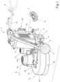
- Figure 1 shows a perspective view of a floor surfacing machine 1, which according to an embodiment is in the form of a floor grinding or polishing machine.
- the floor surfacing machine 1 has a frame 2 which is carried by a first wheel 3 and a second wheel 4.
- the first wheel 3 is operated by means of a first drive motor 5, whereas the second wheel 4 is operated by means of a second drive motor 6.
- the floor surfacing machine 1 can be operated remotely, i.e. it can be operated by an operator who is standing beside the machine 1 and is using a remote control 7 for controlling various operating parameters. More precisely, the remote control 7 is used to control the operation of the two drive motors 5, 6 so as to control the speed of each wheel 3, 4 independently. By varying the speed of the left and right wheel 3, 4, respectively, the floor surfacing machine 1 can be made to turn to the right or left direction.
- the remote control 7 can also be used to control additional parameters required for the floor grinding operation.
- the floor surfacing machine 1 can be moved over a floor surface 8 in order to implement for example a grinding or polishing process.
- the floor surfacing machine 1 can be operated manually, i.e. it can be operated by an operator who will then be moving the machine 1 over the floor surface 8.
- the machine 1 is equipped with a handle 9 which the operator then uses to maneouvre the machine 1 along the floor 8 as required.
- the handle 9 is shown in a condition in which it is folded together, and also in an unfolded condition (which is indicated with broken lines) in which it is suitable for manual operation of the floor surfacing machine 1.
- the handle 9 is suitably configured to assume one or more further positions which are not shown in Fig. 1 .
- the handle 9 can be configured to assume a condition in which it extends in a generally vertical direction. Such a condition is suitable when the floor grinding machine 1 is operated by means of the remote control 7.
- the remote control 7 is provided with a control unit 10 which, during remote operation of the floor grinding machine 1, is configured for communicating wirelessly with a main control unit (not visible in Fig. 1 ) which is arranged inside an electrical cabinet 11. Also, the handle 9 is provided with a handle control panel 12 which is used to operate the machine 1 during a manual mode of operation, and which also supports a panel control unit (not visible in Fig. 1 ) which is configured to communicate with the above-mentioned main control unit, suitably via a wired connection.
- an operator When remotely controlling the floor surfacing machine 1, an operator should be positioned so as to have a clear view of the floor surfacing machine 1 and the floor surface 8 that is to be treated, suitably by being in the immediate vicinity of the floor surfacing machine 1 and the floor surface 8. The operation of the machine 1 is then controlled by means of the remote control 7.
- the first drive motor 5 is mechanically connected to the first wheel 3 whereas the second drive motor 6 is mechanically connected to the second wheel 4.
- the drive motors 5, 6 are in the form of brushless DC motors with suitable transmission units (not shown in Figure 1 and Figure 2 ) which are connected to each drive wheel 3, 4.
- suitable transmission units not shown in Figure 1 and Figure 2
- other types of motor arrangements are possible within the scope of the invention.
- the floor surfacing machine 1 comprises a surfacing apparatus, according to an embodiment in the form of a planetary head 13 which is rotatably mounted to the frame 2 and comprises a cylindrical wall 14 which is closed at its upper end by means of a top plate 15 and at its lower end by means of a bottom plate 16 (not visible in Fig. 1 but shown in Fig. 3 ).
- the floor surfacing machine comprises three satellite surfacing heads 17, 18, 19, including grinding discs, that are rotatably mounted within the circumference of the planetary head 13, where the satellite surfacing heads 17, 18, 19 are adapted for treating the floor surface 8 by means of for example grinding or polishing.
- the invention is not limited to machines having three satellite surfacing heads, i.e. the number of surfacing heads may vary.
- a motor mounting plate 20 is mounted above the planetary head 13.
- a third motor 21, with a gearbox 21a, is provided in order to drive the planetary head 13.
- the floor surfacing machine 1 further comprises a fourth motor 22 which is mounted on the motor mounting plate 20 and which is arranged to drive the satellite surfacing heads 17, 18, 19 in a manner so that the planetary head 13 and the satellite surfacing heads 17, 18, 19 are independently operable.
- the third motor 21 and the fourth motor 22 define a motor arrangement and operate entirely independently, and as a result, the satellite surfacing heads 17, 18, 19 and planetary head 13 are driven independently and can be driven in a mutually opposing direction of rotation or in the same direction of rotation, and can be driven at different speeds independently of one another.
- the arrangement with independently driven satellite surfacing heads 17, 18, 19 and planetary head 13 provides enhanced control, stability and productivity for a remotely controlled floor surfacing machine 1.
- the fourth motor 22 is connected to a first motor axis 23 that extends through the top plate 15, and is connected to a first belt pulley 24 that is arranged to drive an endless belt 25 that further is guided by means of a second belt pulley 26, a third belt pulley 27, a fourth belt pulley 28 and a fifth belt pulley 29.
- Each one of the second belt pulley 26, third belt pulley 27, the fourth belt pulley 28 and the fifth belt pulley 29 is rotatably arranged so as to guide the endless belt 25 around the satellite surfacing heads 19, 20, 21 such that they are propelled when the fourth motor 22 drives the endless belt 25.
- the fifth belt pulley 29 is attached, via a tensioning device 30, to a rotating part 13a of the planetary head 13.
- the tensioning device 30 is arranged to press the fifth belt pulley 29 against the endless belt 25 with a certain force, for example by means of a spring arrangement (not shown).
- the endless belt 25 is tightened around the belt pulleys 24, 26, 27, 28, 29 and the satellite surfacing heads 17, 18, 19 (which are shown without their grinding discs in Figure 4 ) to a certain extent that suitably is adjustable by means of the tensioning device 30 which for this purpose is configured with a pivotable and adjustable arm connected to the top plate 15.
- the tensioning device 30 should also be releasable such that the endless belt 25 is untightened, for example if the endless belt 25 needs to be replaced.
- the third motor 21 is connected to its gear-box 21a from which a motor axis (not shown) extends.
- Two generally identical driving cog-wheels 32, 33 are attached to the second motor axis.
- the planetary head 13 comprises a circumferentially running top rim 34 that is mounted to the top plate 15.
- a driving chain arrangement 35 is attached, suitably by welding.
- the driving chain arrangement 35 is arranged to engage the driving cog-wheels 32, 33 such that when the driving cog-wheels 32, 33 are propelled by means of the third motor 21, these rotate the chain arrangement 35 which in turn rotates the planetary head 13 to which it is attached via the top rim 34.
- the handle control panel 12 is used for controlling, for example, the direction of rotation and the speed of the satellite surfacing heads 17, 18, 19, and the direction of rotation and speed of the planetary head 13.
- the handle control panel 12 can also be used for selecting between manual operation and remote operation.
- the remote control 7 is also used for controlling, for exampe, the direction of rotation and the speed of the satellite surfacing heads 17, 18, 19, the direction of rotation and speed of the planetary head 13, and further relevant parameters.
- the third motor 21 may be arranged to propel the planetary head 13 by means of an endless belt that runs around the outer surface of the top rim, where the endless belt is connected to the third motor 21 by means of a pulley transmission arrangement (not shown).
- the positions of the third motor 21 and the fourth motor 22 may be altered in dependence of how they are arranged to propel the planetary head 13 and the satellite surfacing heads 17, 18, 19.
- Figure 6 shows a perspective view of the first drive wheel 3.
- Figure 7 shows a cross-sectional view of said first drive wheel 3.
- the second driving wheel 4 (not shown in Figures 6 or 7 ) is constructed in a similar manner as the first drive wheel 3.
- the first drive wheel 3 comprises a tyre 36 which is mounted on a rim 37, and furthermore a wheel hub 38 which is configured for carrying a drive axle shaft (not shown in Figure 6 ) of the first drive motor 5.
- the wheel hub 38 is supported by means of a wheel bearing 39 (see Figure 7 ).
- a locking pin 40 is used in order to lock the wheel 3 to the corresponding drive motor 5 during operation.
- the wheel 3 is locked in this manner before grinding operation by means of the planetary head 13 is started.
- this is particularly important during remote operation of the floor surfacing machine 1 by means of the remote control 7.
- the locking pin 40 is arranged as shown in Figure 7 in a manner so that it extends through a bore 41 in the wheel rim 37 and also through a further bore 42 in the wheel hub 38. In this manner, the wheel 3 is locked so that it rotates when the corresponding drive motor axle rotates.
- FIG 8 shows the locking pin 40 in greater detail.
- the locking pin 40 comprises a pin element 43 with a head 44, wherein the pin element 43 extends inside a cylindrical sleeve 45. Furthermore, the pin element 43 can be displaced longitudinally inside the sleeve 45 so that the tip 46 of the locking pin 40 protrudes outside the sleeve 45. Also, the locking pin 40 comprises a spring element 47 which acts so as to force the tip 46 of the locking pin 40 in a direction towards the bore 42 in the wheel hub 38.
- the locking pin arrangement 40 can be mounted in the wheel rim 37 so that it may assume two different positions.
- Figure 7 shows the locking pin 40 in a locked position, i.e. when the first drive wheel 3 is arranged so that the pin tip 46 extends into the corresponding bore 42 in the wheel hub 38, i.e. so that the rim 37 is locked to the wheel hub 38.
- the locking pin 40 is arranged to assume a further position, i.e. a position in which it does not extend through the bore in the wheel hub 38 but instead so that the tip 46 of the locking pin 40 is withdrawn from the bore 42 in the wheel hub 38.
- the locking pin 40 is mounted in the rim 37 during both its active and inactive position.
- the pin element 43 is pulled out in relation to the sleeve 45 (so that the tip 46 is no longer inserted into the hub 38) after which the pin element is turned in relation to the sleeve in order to lock the locking pin 40 in its inactive position.
- the pin element 43 In order to move the locking pin 40 to its active position, the pin element 43 is turned back, so that the tip 46 is forced towards its active position by means of the spring element 47. More precisely, the locking pin 40 can be pushed into a bore of the hub 38 by rotating the hub 38. To this end, the hub 38 is provided with a plurality of bores so that the locking pin 40 easily can be positioned into one of them.
- the locking pin 40 may be in its unlocked condition for example when the floor surfacing machine 1 is to be operated manually, i.e. without assistance from the drive motors 5, 6. However, during remote operation, it is essential that the locking pin 40 is positioned in its locked condition before the planetary head 13 is operated.
- Figure 9 is a schematic view of an embodiment involving a safety arrangement for the floor surfacing machine as described above and disclosing the first wheel 3 which is operated by means of the first drive motor 5 and the second wheel 4 which is operated by means of the second drive motor 6.
- the first drive motor 5 has a first output axle 48 which is connected to a first transmission 49 and the second drive motor 6 has a second output axle 50 which is connected to a second transmission 51.
- the first transmission 49 is connected to the first drive wheel 3 via a first drive axle 52
- the second transmission 51 is connected to the second drive wheel 4 via a second drive axle 53.
- the drive motors 5, 6 are configured so as be operated by means of the remote control 7, which is provided with a control unit 10 as mentioned above.
- the control unit 10 is configured for communicating in a wireless manner with a main control unit 11a arranged inside an electrical cabinet (see also Figure 1 ).
- the main control unit 11a is not visible in Figure 1 but is shown in a schematical manner in Figure 9 .
- the remote control 7 can be connected remotely to the main control unit 11a in order to control the drive motors 5, 6.
- Other parameters involving the operation of the floor surfacing machine 1 can also be controlled by means of the remote control 7, such as the speed and direction of rotation of the planetary head 13 and the satellite surfacing heads 17, 18, 19 by means of the third motor 21 and the fourth motor 22, respectively.
- the embodiment shown in Figure 9 also comprises a power supply 54 for the drive motors 5,6 which is shown in a schematical manner.
- the power supply 54 is controlled by means of the main control unit 11a and is also associated with a current measuring unit 55 which is configured for measuring the current supplied by the power supply 54 to each one of the two drive motors 5, 6. Even though the current measuring unit 55 is arranged for measuring the current supplied to each individual drive motor 5, 6 it is shown schematically as a single unit in Figure 9 .
- Figure 9 also shows a first Hall sensor 56 for sensing the rotational speed n1 of the first output axle 48 and also a second Hall sensor 57 for sensing the rotational speed n2 of the second output axle 50.
- the two Hall sensors 56, 57 are connected to the main control unit 11a.
- each drive motor 5, 6 is measured by means of the current measuring unit 55.
- the current drawn by each motor 5, 6 can be said to correspond to the torque provided by each corresponding wheel 3, 4 during operation.
- the torque which is required for attempting to rotate the wheel 3 via the first drive axle 52 is considered to be relatively high. This is interpreted by the main control unit 11a as an operating condition in which the wheel 3 rotates with a substantial amount of resistance, i.e. a situation in which the wheel 3 is in fact locked by means of its locking pin 40.
- the control unit 11 interprets the control unit 11 as an operating condition in which the drive motor 5 rotates easily, i.e. a situation in which the wheel 3 is not locked by means of its locking pin 40.
- the safety measures mentioned above are carried out through control by means of the main control unit 11a.
- the above-mentioned torque measurements i.e. the tests for determining whether each wheel 3, 4 is locked by its locking pin
- this start-up sequence is executed during a relatively short time period immediately after a start of the floor surfacing machine, i.e. after the two drive motors 3, 4, the third motor 21 and the fourth motor 22 have been started and the grinding operation is about to be initiated by an operator.
- the main control unit 11a is arranged for determining the rotational speed n1, n2 of the two output axles 48, 50 as detected by means of the Hall sensors 56, 57. If the rotational speed n1 of the first output axle 48 is relatively high, this corresponds to a condition in which the torque required for rotating the corresponding wheel 3 is relatively low. This is interpreted by the main control unit 11a as a situation in which the first output axle 48 rotates relatively freely, i.e. a situation in which the wheel 3 is not locked by means of its locking pin 40.
- the rotational speed n1 of the first drive wheel 3 is relatively low, it can be expected that the torque which is required for rotating the first wheel 3 is relatively high. This is interpreted by the main control unit 11a as a situation in which the drive motor 5 rotates with a certain amount of resistance, i.e. a situation in which the wheel 3 is in fact locked by means of its locking pin 40.
- the main control unit 11a is configured for preventing operation of the planetary head 13 and the satellite surfacing heads 17, 18, 19, i.e. preventing operation of the third motor 21 and the fourth motor 22, if said required torque is lower than a predetermined limit value.
- a limit value is adapted so as to correspond to a rotational speed of the axle 48 which clearly is indicative of a condition in which the locking pin 40 is not in place so as to lock the wheel 3.
- measurements related to both the current to the drive motors 5, 6 and also the rotational speed of the drive wheels 3, 4 can be combined in order to determine whether any of the drive wheels 3, 4, can be considered to be unlocked.
- a current measurement can be carried only when any, or each, of the wheels 3, 4 rotates with a speed which is higher than a predetermined threshold speed.
- the main control unit 11a is configured so that when an operator activates the main control unit 11a during a start-up phase of the floor surfacing machine 1, there is a control whether the drive motors 5, 6 can run without essentially any resistance. If this is the case, this means that the drive wheels 3, 4 are not locked by the spring pin 40. As a consequence, operation of the surfacing apparatus in the form of the planetary head 13 is prevented. If, on the other hand, the torque for operating the drive wheels 3, 4 is higher than a certain threshold value, the operation of the planetary head 13 and the satellite surfacing heads 17, 18, 19 can be started.
- the invention is not limited to the above, but may vary freely within the scope of the dependent claims.
- other sensor types can be used instead of the Hall sensors, for example torque sensor devices being associated with each outgoing axle of a corresponding drive motor.
- the remote unit 7 may be arranged to communicate with the main control unit 11a by means of other means than radio signals, for example optical or sonic signals.
- the remote unit 7 can in principle also be connected to the main control unit 11a via an electric wire.
Landscapes
- Engineering & Computer Science (AREA)
- Mechanical Engineering (AREA)
- Grinding Of Cylindrical And Plane Surfaces (AREA)
Claims (12)
- Machine de surfaçage de sol (1) comprenant un système de sécurité, au moins une roue d'entraînement (3, 4), un système de moteur (5, 6) servant à propulser ladite roue d'entraînement (3, 4), un appareil de surfaçage (13) et une unité de commande (10, 11a) servant à commander l'actionnement dudit système de moteur (5, 6) et dudit appareil de surfaçage (13), caractérisée en ce que ledit système de sécurité comprend au moins une unité de détection (55 ; 56, 57) reliée à ladite unité de commande (10, 11a) et propre à déterminer un couple requis pour l'actionnement de chaque roue d'entraînement (3, 4) et en ce que ladite unité de commande (10, 11a) est conçue pour empêcher l'actionnement dudit appareil de surfaçage (13) si ledit couple requis est inférieur à une valeur limite prédéterminée, ladite unité de commande (10, 11a) étant conçue pour empêcher l'actionnement dudit appareil de surfaçage (13) par l'arrêt desdits premier système de moteur (5, 6) et/ou second système de moteur (21, 22).
- Machine de surfaçage de sol (1) selon la revendication 1, caractérisée en ce que ledit système de moteur (5, 6) comprend au moins un moteur à CC sans balai.
- Machine de surfaçage de sol (1) selon la revendication 1 ou 2, caractérisée en ce que ledit appareil de surfaçage (13) comprend une tête planétaire (13) qui est installée de manière rotative sur une structure de châssis (2) et au moins une tête de surfaçage satellite (17, 18, 19) qui est installée de manière rotative sur la tête planétaire (13), et un second système de moteur (21, 22) servant à propulser ladite tête planétaire (13) et ladite au moins une tête de surfaçage satellite (17, 18, 19).
- Machine de surfaçage de sol (1) selon la revendication 3, caractérisée en ce que ledit second système de moteur (18, 22) comprend un moteur (22) qui est conçu pour propulser les têtes de surfaçage satellites (17, 18, 19) et un autre moteur (21) qui est conçu pour propulser la tête planétaire (13), de telle sorte que la tête planétaire (13) et les têtes de surfaçage satellites (17, 18, 19) puissent être actionnées de manière indépendante.
- Machine de surfaçage de sol (1) selon l'une quelconque des revendications précédentes, caractérisée en ce que ledit détecteur (55) comprend une unité de mesure de courant conçue pour détecter le courant fourni audit système de moteur (5, 6), ledit courant indiquant le couple requis pour l'actionnement de chaque roue d'entraînement (3, 4) correspondante.
- Machine de surfaçage de sol (1) selon l'une quelconque des revendications 1 à 4, caractérisée en ce que ledit détecteur (56, 57) comprend un capteur à effet Hall conçu pour détecter la vitesse d'au moins un essieu de sortie (48 ; 50) dudit système de moteur (5, 6).
- Machine de surfaçage de sol (1) selon l'une quelconque des revendications précédentes, caractérisée en ce que ladite unité de commande (10, 11a) est au moins partiellement placée dans un dispositif de commande à distance (7).
- Machine de surfaçage de sol (1) selon l'une quelconque des revendications précédentes, caractérisée en ce que ladite au moins une roue d'entraînement (3, 4) est associée à une goupille d'assujettissement (40) conçue pour assujettir ladite au moins une roue d'entraînement (3, 4) audit au moins un essieu de sortie (48 ; 50) dudit système de moteur (5, 6).
- Système de sécurité faisant partie de la machine de surfaçage de sol (1) selon l'une quelconque des revendications précédentes.
- Procédé d'obtention d'une fonction de sécurité dans une machine de surfaçage de sol (1) comportant au moins une roue d'entraînement (3, 4), un système de moteur (5, 6) servant à propulser ladite roue d'entraînement (3, 4), et un appareil de surfaçage (13), ledit procédé comprenant :- commander l'actionnement dudit système de moteur (5, 6) et dudit appareil de surfaçage (13) au moyen d'une unité de commande (10, 11) ;caractérisé en ce que ledit procédé comprend, en outre :- déterminer un couple requis pour l'actionnement de ladite au moins une roue d'entraînement (3, 4) ;- déterminer si ledit couple requis est inférieur à une valeur limite prédéterminée ; et- empêcher l'actionnement de l'appareil de surfaçage (13) si ledit couple requis est inférieur à ladite valeur limite prédéterminée,ledit appareil de surfaçage (13) comprenant une tête planétaire (13) propulsée par un second système de moteur (21, 22), ledit procédé comprenant, en outre :- empêcher l'actionnement de l'appareil de surfaçage (13) par l'arrêt desdits premier système de moteur (5, 6) et/ou second système de moteur (21, 22).
- Procédé selon la revendication 10, ledit procédé comprenant, en outre :- mesurer le courant fourni audit système de moteur (5, 6), ledit courant indiquant le couple requis pour l'actionnement de chaque roue d'entraînement (3, 4) correspondante ; et- empêcher l'actionnement de l'appareil de surfaçage (13) si le courant mesuré est inférieur à une valeur limite prédéterminée.
- Procédé selon la revendication 10 ou 11, ledit procédé comprenant, en outre :- mesurer la vitesse de rotation (n1, n2) d'un essieu de sortie (48 ; 50) de chaque roue d'entraînement (3, 4), ladite vitesse de rotation (n1, n2) indiquant le couple requis pour l'actionnement de chaque roue d'entraînement (3, 4) ; et- empêcher l'actionnement de l'appareil de surfaçage (13) si la vitesse (n1, n2) mesurée est supérieure à une valeur limite prédéterminée.
Applications Claiming Priority (2)
| Application Number | Priority Date | Filing Date | Title |
|---|---|---|---|
| SE1651353A SE540015C2 (en) | 2016-10-17 | 2016-10-17 | Safety arrangement and method for a floor surfacing machine |
| PCT/SE2017/051006 WO2018074965A1 (fr) | 2016-10-17 | 2017-10-12 | Agencement de sécurité et procédé pour une machine à surfacer les sols |
Publications (3)
| Publication Number | Publication Date |
|---|---|
| EP3525985A1 EP3525985A1 (fr) | 2019-08-21 |
| EP3525985A4 EP3525985A4 (fr) | 2019-10-23 |
| EP3525985B1 true EP3525985B1 (fr) | 2023-06-14 |
Family
ID=61236534
Family Applications (1)
| Application Number | Title | Priority Date | Filing Date |
|---|---|---|---|
| EP17862867.3A Active EP3525985B1 (fr) | 2016-10-17 | 2017-10-12 | Agencement de sécurité et procédé pour une machine à surfacer les sols |
Country Status (6)
| Country | Link |
|---|---|
| US (1) | US10842337B2 (fr) |
| EP (1) | EP3525985B1 (fr) |
| CN (2) | CN112692731B (fr) |
| AU (1) | AU2017347300B2 (fr) |
| SE (1) | SE540015C2 (fr) |
| WO (1) | WO2018074965A1 (fr) |
Families Citing this family (9)
| Publication number | Priority date | Publication date | Assignee | Title |
|---|---|---|---|---|
| USD876501S1 (en) * | 2018-10-05 | 2020-02-25 | Diamond Productions Ltd. | Polishing machine attachment for grinding and polishing concrete |
| SE1950959A1 (en) * | 2019-08-22 | 2020-11-03 | Husqvarna Ab | A drive arrangement for a floor surfacing machine and a floor surfacing machine |
| USD947909S1 (en) | 2019-09-04 | 2022-04-05 | Husqvarna Ab | Power grinder |
| USD947908S1 (en) | 2019-09-04 | 2022-04-05 | Husqvarna Ab | Power grinder |
| USD943226S1 (en) * | 2019-09-04 | 2022-02-08 | Husqvarna Ab | Power grinder |
| SE543845C2 (en) * | 2019-12-05 | 2021-08-10 | Husqvarna Ab | A floor surfacing machine with different drive motors |
| CN111390681A (zh) * | 2020-05-15 | 2020-07-10 | 阿特钚锐秦皇岛科技有限公司 | 模块式地坪研磨机 |
| SE544465C2 (en) | 2021-05-12 | 2022-06-07 | Husqvarna Ab | A tool wear indicator for concrete surface processing equipment |
| EP4353923A1 (fr) * | 2022-10-10 | 2024-04-17 | Milwaukee Electric Tool Corporation | Commutateur de sécurité pour lisseuse alimentée par bloc-batterie |
Citations (2)
| Publication number | Priority date | Publication date | Assignee | Title |
|---|---|---|---|---|
| EP1492646B1 (fr) * | 2002-03-12 | 2010-09-15 | HTC Sweden AB | Système de meuler les surfaces de sol |
| EP2110295B1 (fr) * | 2008-04-18 | 2012-02-29 | Kanzaki Kokyukoki Mfg. Co., Ltd. | Véhicule électrique pour travailler le sol |
Family Cites Families (28)
| Publication number | Priority date | Publication date | Assignee | Title |
|---|---|---|---|---|
| US3212218A (en) * | 1962-07-05 | 1965-10-19 | American Mach & Foundry | Levelling system for bowling lane sanding machine |
| DE1453097A1 (de) * | 1964-06-10 | 1969-01-02 | Rheinische Nadelfab Gmbh | Fussbodenpflege- und -reinigungsmaschine |
| US4232980A (en) * | 1979-01-08 | 1980-11-11 | Stone Construction Equipment, Inc. | Rotary power trowel |
| SE419053B (sv) * | 1979-05-17 | 1981-07-13 | Dynapac Maskin Ab | Slipmaskin for bearbetning av plana ytor sasom golv av sten, betong eller liknande hardnat material |
| US4435870A (en) * | 1980-03-13 | 1984-03-13 | Tucker Jeffery R | Floor machine |
| US4542551A (en) * | 1983-09-30 | 1985-09-24 | Mcgraw-Edison Company | Rotary floor maintenance device |
| US4757566A (en) * | 1987-07-27 | 1988-07-19 | Tennant Company | Control of torque in floor maintenance tools by drive motor load |
| US5543672A (en) * | 1989-10-18 | 1996-08-06 | Yazaki Corporation | Rotation detecting device with magnet brake |
| DE69229670T2 (de) * | 1992-04-01 | 2000-01-27 | Penguin Wax Co. Ltd., Osaka | Bodenbehandlungsmaschine |
| JPH064130A (ja) * | 1992-06-23 | 1994-01-14 | Sanyo Electric Co Ltd | 掃除ロボット |
| US5369236A (en) * | 1992-10-01 | 1994-11-29 | Black & Decker Inc. | Control switch arrangement for orbital polisher |
| US6389875B1 (en) * | 1998-10-02 | 2002-05-21 | Ralph L. Barnett | Zero speed indicating devices and process of testing same |
| DE19857061C2 (de) * | 1998-12-10 | 2000-11-02 | Hilti Ag | Verfahren und Einrichtung zur Vermeidung von Unfällen bei handgeführten Werkzeugmaschinen durch Werkzeugblockieren |
| US6231432B1 (en) | 1999-11-12 | 2001-05-15 | Pearl Abrasive Company | Floor treatment machine with torque limiter |
| US6715178B2 (en) * | 2002-06-05 | 2004-04-06 | Pasquale Graceffo | Floor polisher conversion kit |
| GB2414283A (en) | 2004-05-06 | 2005-11-23 | Dyson Ltd | A slip responsive clutch in a vacuum cleaner |
| US8172649B2 (en) * | 2009-01-28 | 2012-05-08 | Onfloor Technologies, L.L.C. | Floor edger and grinder device |
| EP2359982A1 (fr) * | 2010-02-22 | 2011-08-24 | Katdangil, Private Stichting | Machine de traitement de sol |
| DE102010043188A1 (de) * | 2010-10-29 | 2012-05-03 | Robert Bosch Gmbh | Ablaufsicherungsvorrichtung |
| US20130189908A1 (en) * | 2012-01-23 | 2013-07-25 | Onfloor Technologies, L.L.C. | Edger Resurfacing Machine |
| CN102785169B (zh) * | 2012-08-03 | 2015-06-17 | 东风康明斯发动机有限公司 | 一种数控外圆磨床的双测速安全保护方法及装置 |
| WO2014058051A1 (fr) | 2012-10-12 | 2014-04-17 | 国際計測器株式会社 | Moteur à deux arbres secondaires, unité moteur, simulateur d'alimentation, dispositif de test de torsion, dispositif de test de torsion de rotation, dispositif de test de pneu, actionneur linéaire et dispositif à vibrations |
| SE539542C2 (en) * | 2014-09-25 | 2017-10-10 | Husqvarna Ab | Floor surfacing machine |
| CN104787025B (zh) * | 2015-04-23 | 2017-11-03 | 吉林博承传动系统科技有限公司 | 一种汽车无动力滑行控制装置及其控制系统和控制方法 |
| CN104856614A (zh) * | 2015-06-01 | 2015-08-26 | 周生方 | 一种扫地机器人的万向轮运动状态检测装置 |
| CN108602184B (zh) * | 2016-02-29 | 2021-06-29 | 工机控股株式会社 | 动力工具 |
| CN105946915B (zh) * | 2016-04-29 | 2017-12-05 | 华中农业大学 | 基于轮毂电机和控制器的手扶电动轻型载运小车 |
| CN105982619A (zh) * | 2016-06-29 | 2016-10-05 | 洛阳圣瑞智能机器人有限公司 | 一种带有抹布旋转装置的智能拖地机器人及方法 |
-
2016
- 2016-10-17 SE SE1651353A patent/SE540015C2/en unknown
-
2017
- 2017-10-12 WO PCT/SE2017/051006 patent/WO2018074965A1/fr not_active Ceased
- 2017-10-12 US US16/341,145 patent/US10842337B2/en active Active
- 2017-10-12 AU AU2017347300A patent/AU2017347300B2/en active Active
- 2017-10-12 CN CN202011618441.XA patent/CN112692731B/zh active Active
- 2017-10-12 CN CN201780064121.4A patent/CN109843507A/zh active Pending
- 2017-10-12 EP EP17862867.3A patent/EP3525985B1/fr active Active
Patent Citations (2)
| Publication number | Priority date | Publication date | Assignee | Title |
|---|---|---|---|---|
| EP1492646B1 (fr) * | 2002-03-12 | 2010-09-15 | HTC Sweden AB | Système de meuler les surfaces de sol |
| EP2110295B1 (fr) * | 2008-04-18 | 2012-02-29 | Kanzaki Kokyukoki Mfg. Co., Ltd. | Véhicule électrique pour travailler le sol |
Also Published As
| Publication number | Publication date |
|---|---|
| AU2017347300B2 (en) | 2023-03-02 |
| CA3038524A1 (fr) | 2018-04-26 |
| EP3525985A4 (fr) | 2019-10-23 |
| SE1651353A1 (en) | 2018-02-27 |
| CN112692731B (zh) | 2022-04-12 |
| WO2018074965A1 (fr) | 2018-04-26 |
| US10842337B2 (en) | 2020-11-24 |
| CN109843507A (zh) | 2019-06-04 |
| US20190239712A1 (en) | 2019-08-08 |
| CN112692731A (zh) | 2021-04-23 |
| AU2017347300A1 (en) | 2019-04-11 |
| SE540015C2 (en) | 2018-02-27 |
| EP3525985A1 (fr) | 2019-08-21 |
Similar Documents
| Publication | Publication Date | Title |
|---|---|---|
| EP3525985B1 (fr) | Agencement de sécurité et procédé pour une machine à surfacer les sols | |
| US5177828A (en) | Missing pad detector for a floor polishing tool | |
| JP6634463B2 (ja) | コンクリート仕上げ装置 | |
| US4783872A (en) | Floor and baseboard treating machine | |
| AU2014223616B2 (en) | Cleaning head assemblies having touch-free attachment and alignment technology | |
| JPS62243521A (ja) | 床面保守作業装置用制御及び監視装置 | |
| US6986397B2 (en) | Power riding trailer for an implement | |
| CA3038524C (fr) | Agencement de securite et procede pour une machine a surfacer les sols | |
| KR101579903B1 (ko) | 원격제어형 피칭머신 | |
| JPH114858A (ja) | ベルト式巻上機 | |
| US10222784B2 (en) | Method for controlling a device system, which comprises a tool device and motorized advancing apparatus | |
| KR101219436B1 (ko) | 모빌랙의 주행장치 | |
| US20200398619A1 (en) | Tyre changing apparatus | |
| US20070102204A1 (en) | Guided airplane relocating device | |
| CN220917556U (zh) | 一种数字化电子牵引器 | |
| CN107128802B (zh) | 航车及其驱动分离装置 | |
| CN114179556B (zh) | 一种自控电动研墨机及自动研墨方法 | |
| KR102254228B1 (ko) | 휠체어 리프트장치용 안전장치 및 이를 구비한 휠체어 리프트장치 | |
| CN109946758A (zh) | 一种具有防撞功能的便于移动的金属探测仪 | |
| KR20220032820A (ko) | 근력보조 휠체어 | |
| CN207751615U (zh) | 用于洗衣机的扭矩检测装置 | |
| KR101529712B1 (ko) | 롤러 회전 토크 측정 장치 및 방법 | |
| CN116221288B (zh) | 一种旋转机组轴套锁紧装置及锁紧方法 | |
| CN210293632U (zh) | 一种具有防护功能的钢结构检测机 | |
| WO1986004633A1 (fr) | Machine de finition de plancher en beton |
Legal Events
| Date | Code | Title | Description |
|---|---|---|---|
| STAA | Information on the status of an ep patent application or granted ep patent |
Free format text: STATUS: THE INTERNATIONAL PUBLICATION HAS BEEN MADE |
|
| PUAI | Public reference made under article 153(3) epc to a published international application that has entered the european phase |
Free format text: ORIGINAL CODE: 0009012 |
|
| STAA | Information on the status of an ep patent application or granted ep patent |
Free format text: STATUS: REQUEST FOR EXAMINATION WAS MADE |
|
| 17P | Request for examination filed |
Effective date: 20190502 |
|
| AK | Designated contracting states |
Kind code of ref document: A1 Designated state(s): AL AT BE BG CH CY CZ DE DK EE ES FI FR GB GR HR HU IE IS IT LI LT LU LV MC MK MT NL NO PL PT RO RS SE SI SK SM TR |
|
| AX | Request for extension of the european patent |
Extension state: BA ME |
|
| A4 | Supplementary search report drawn up and despatched |
Effective date: 20190919 |
|
| RIC1 | Information provided on ipc code assigned before grant |
Ipc: B24B 7/18 20060101ALI20190914BHEP Ipc: A47L 11/40 20060101ALI20190914BHEP Ipc: A47L 11/14 20060101ALI20190914BHEP Ipc: B24B 55/00 20060101AFI20190914BHEP |
|
| DAV | Request for validation of the european patent (deleted) | ||
| DAX | Request for extension of the european patent (deleted) | ||
| GRAP | Despatch of communication of intention to grant a patent |
Free format text: ORIGINAL CODE: EPIDOSNIGR1 |
|
| STAA | Information on the status of an ep patent application or granted ep patent |
Free format text: STATUS: GRANT OF PATENT IS INTENDED |
|
| INTG | Intention to grant announced |
Effective date: 20220719 |
|
| GRAJ | Information related to disapproval of communication of intention to grant by the applicant or resumption of examination proceedings by the epo deleted |
Free format text: ORIGINAL CODE: EPIDOSDIGR1 |
|
| STAA | Information on the status of an ep patent application or granted ep patent |
Free format text: STATUS: REQUEST FOR EXAMINATION WAS MADE |
|
| INTC | Intention to grant announced (deleted) | ||
| RAP3 | Party data changed (applicant data changed or rights of an application transferred) |
Owner name: HUSQVARNA AB |
|
| GRAP | Despatch of communication of intention to grant a patent |
Free format text: ORIGINAL CODE: EPIDOSNIGR1 |
|
| STAA | Information on the status of an ep patent application or granted ep patent |
Free format text: STATUS: GRANT OF PATENT IS INTENDED |
|
| INTG | Intention to grant announced |
Effective date: 20230113 |
|
| GRAS | Grant fee paid |
Free format text: ORIGINAL CODE: EPIDOSNIGR3 |
|
| GRAA | (expected) grant |
Free format text: ORIGINAL CODE: 0009210 |
|
| STAA | Information on the status of an ep patent application or granted ep patent |
Free format text: STATUS: THE PATENT HAS BEEN GRANTED |
|
| AK | Designated contracting states |
Kind code of ref document: B1 Designated state(s): AL AT BE BG CH CY CZ DE DK EE ES FI FR GB GR HR HU IE IS IT LI LT LU LV MC MK MT NL NO PL PT RO RS SE SI SK SM TR |
|
| REG | Reference to a national code |
Ref country code: CH Ref legal event code: EP |
|
| REG | Reference to a national code |
Ref country code: DE Ref legal event code: R096 Ref document number: 602017070302 Country of ref document: DE |
|
| REG | Reference to a national code |
Ref country code: AT Ref legal event code: REF Ref document number: 1578881 Country of ref document: AT Kind code of ref document: T Effective date: 20230715 |
|
| P01 | Opt-out of the competence of the unified patent court (upc) registered |
Effective date: 20230609 |
|
| REG | Reference to a national code |
Ref country code: LT Ref legal event code: MG9D |
|
| REG | Reference to a national code |
Ref country code: NL Ref legal event code: MP Effective date: 20230614 |
|
| PG25 | Lapsed in a contracting state [announced via postgrant information from national office to epo] |
Ref country code: SE Free format text: LAPSE BECAUSE OF FAILURE TO SUBMIT A TRANSLATION OF THE DESCRIPTION OR TO PAY THE FEE WITHIN THE PRESCRIBED TIME-LIMIT Effective date: 20230614 Ref country code: NO Free format text: LAPSE BECAUSE OF FAILURE TO SUBMIT A TRANSLATION OF THE DESCRIPTION OR TO PAY THE FEE WITHIN THE PRESCRIBED TIME-LIMIT Effective date: 20230914 Ref country code: ES Free format text: LAPSE BECAUSE OF FAILURE TO SUBMIT A TRANSLATION OF THE DESCRIPTION OR TO PAY THE FEE WITHIN THE PRESCRIBED TIME-LIMIT Effective date: 20230614 |
|
| REG | Reference to a national code |
Ref country code: AT Ref legal event code: MK05 Ref document number: 1578881 Country of ref document: AT Kind code of ref document: T Effective date: 20230614 |
|
| PG25 | Lapsed in a contracting state [announced via postgrant information from national office to epo] |
Ref country code: RS Free format text: LAPSE BECAUSE OF FAILURE TO SUBMIT A TRANSLATION OF THE DESCRIPTION OR TO PAY THE FEE WITHIN THE PRESCRIBED TIME-LIMIT Effective date: 20230614 Ref country code: NL Free format text: LAPSE BECAUSE OF FAILURE TO SUBMIT A TRANSLATION OF THE DESCRIPTION OR TO PAY THE FEE WITHIN THE PRESCRIBED TIME-LIMIT Effective date: 20230614 Ref country code: LV Free format text: LAPSE BECAUSE OF FAILURE TO SUBMIT A TRANSLATION OF THE DESCRIPTION OR TO PAY THE FEE WITHIN THE PRESCRIBED TIME-LIMIT Effective date: 20230614 Ref country code: LT Free format text: LAPSE BECAUSE OF FAILURE TO SUBMIT A TRANSLATION OF THE DESCRIPTION OR TO PAY THE FEE WITHIN THE PRESCRIBED TIME-LIMIT Effective date: 20230614 Ref country code: HR Free format text: LAPSE BECAUSE OF FAILURE TO SUBMIT A TRANSLATION OF THE DESCRIPTION OR TO PAY THE FEE WITHIN THE PRESCRIBED TIME-LIMIT Effective date: 20230614 Ref country code: GR Free format text: LAPSE BECAUSE OF FAILURE TO SUBMIT A TRANSLATION OF THE DESCRIPTION OR TO PAY THE FEE WITHIN THE PRESCRIBED TIME-LIMIT Effective date: 20230915 |
|
| PG25 | Lapsed in a contracting state [announced via postgrant information from national office to epo] |
Ref country code: FI Free format text: LAPSE BECAUSE OF FAILURE TO SUBMIT A TRANSLATION OF THE DESCRIPTION OR TO PAY THE FEE WITHIN THE PRESCRIBED TIME-LIMIT Effective date: 20230614 |
|
| PG25 | Lapsed in a contracting state [announced via postgrant information from national office to epo] |
Ref country code: SK Free format text: LAPSE BECAUSE OF FAILURE TO SUBMIT A TRANSLATION OF THE DESCRIPTION OR TO PAY THE FEE WITHIN THE PRESCRIBED TIME-LIMIT Effective date: 20230614 |
|
| PG25 | Lapsed in a contracting state [announced via postgrant information from national office to epo] |
Ref country code: IS Free format text: LAPSE BECAUSE OF FAILURE TO SUBMIT A TRANSLATION OF THE DESCRIPTION OR TO PAY THE FEE WITHIN THE PRESCRIBED TIME-LIMIT Effective date: 20231014 |
|
| PG25 | Lapsed in a contracting state [announced via postgrant information from national office to epo] |
Ref country code: SM Free format text: LAPSE BECAUSE OF FAILURE TO SUBMIT A TRANSLATION OF THE DESCRIPTION OR TO PAY THE FEE WITHIN THE PRESCRIBED TIME-LIMIT Effective date: 20230614 Ref country code: SK Free format text: LAPSE BECAUSE OF FAILURE TO SUBMIT A TRANSLATION OF THE DESCRIPTION OR TO PAY THE FEE WITHIN THE PRESCRIBED TIME-LIMIT Effective date: 20230614 Ref country code: RO Free format text: LAPSE BECAUSE OF FAILURE TO SUBMIT A TRANSLATION OF THE DESCRIPTION OR TO PAY THE FEE WITHIN THE PRESCRIBED TIME-LIMIT Effective date: 20230614 Ref country code: PT Free format text: LAPSE BECAUSE OF FAILURE TO SUBMIT A TRANSLATION OF THE DESCRIPTION OR TO PAY THE FEE WITHIN THE PRESCRIBED TIME-LIMIT Effective date: 20231016 Ref country code: IS Free format text: LAPSE BECAUSE OF FAILURE TO SUBMIT A TRANSLATION OF THE DESCRIPTION OR TO PAY THE FEE WITHIN THE PRESCRIBED TIME-LIMIT Effective date: 20231014 Ref country code: EE Free format text: LAPSE BECAUSE OF FAILURE TO SUBMIT A TRANSLATION OF THE DESCRIPTION OR TO PAY THE FEE WITHIN THE PRESCRIBED TIME-LIMIT Effective date: 20230614 Ref country code: CZ Free format text: LAPSE BECAUSE OF FAILURE TO SUBMIT A TRANSLATION OF THE DESCRIPTION OR TO PAY THE FEE WITHIN THE PRESCRIBED TIME-LIMIT Effective date: 20230614 Ref country code: AT Free format text: LAPSE BECAUSE OF FAILURE TO SUBMIT A TRANSLATION OF THE DESCRIPTION OR TO PAY THE FEE WITHIN THE PRESCRIBED TIME-LIMIT Effective date: 20230614 |
|
| PG25 | Lapsed in a contracting state [announced via postgrant information from national office to epo] |
Ref country code: PL Free format text: LAPSE BECAUSE OF FAILURE TO SUBMIT A TRANSLATION OF THE DESCRIPTION OR TO PAY THE FEE WITHIN THE PRESCRIBED TIME-LIMIT Effective date: 20230614 |
|
| REG | Reference to a national code |
Ref country code: DE Ref legal event code: R097 Ref document number: 602017070302 Country of ref document: DE |
|
| PLBE | No opposition filed within time limit |
Free format text: ORIGINAL CODE: 0009261 |
|
| STAA | Information on the status of an ep patent application or granted ep patent |
Free format text: STATUS: NO OPPOSITION FILED WITHIN TIME LIMIT |
|
| PG25 | Lapsed in a contracting state [announced via postgrant information from national office to epo] |
Ref country code: DK Free format text: LAPSE BECAUSE OF FAILURE TO SUBMIT A TRANSLATION OF THE DESCRIPTION OR TO PAY THE FEE WITHIN THE PRESCRIBED TIME-LIMIT Effective date: 20230614 |
|
| PG25 | Lapsed in a contracting state [announced via postgrant information from national office to epo] |
Ref country code: SI Free format text: LAPSE BECAUSE OF FAILURE TO SUBMIT A TRANSLATION OF THE DESCRIPTION OR TO PAY THE FEE WITHIN THE PRESCRIBED TIME-LIMIT Effective date: 20230614 |
|
| 26N | No opposition filed |
Effective date: 20240315 |
|
| PG25 | Lapsed in a contracting state [announced via postgrant information from national office to epo] |
Ref country code: SI Free format text: LAPSE BECAUSE OF FAILURE TO SUBMIT A TRANSLATION OF THE DESCRIPTION OR TO PAY THE FEE WITHIN THE PRESCRIBED TIME-LIMIT Effective date: 20230614 Ref country code: IT Free format text: LAPSE BECAUSE OF FAILURE TO SUBMIT A TRANSLATION OF THE DESCRIPTION OR TO PAY THE FEE WITHIN THE PRESCRIBED TIME-LIMIT Effective date: 20230614 Ref country code: MC Free format text: LAPSE BECAUSE OF FAILURE TO SUBMIT A TRANSLATION OF THE DESCRIPTION OR TO PAY THE FEE WITHIN THE PRESCRIBED TIME-LIMIT Effective date: 20230614 |
|
| REG | Reference to a national code |
Ref country code: CH Ref legal event code: PL |
|
| REG | Reference to a national code |
Ref country code: BE Ref legal event code: MM Effective date: 20231031 |
|
| PG25 | Lapsed in a contracting state [announced via postgrant information from national office to epo] |
Ref country code: LU Free format text: LAPSE BECAUSE OF NON-PAYMENT OF DUE FEES Effective date: 20231012 |
|
| PG25 | Lapsed in a contracting state [announced via postgrant information from national office to epo] |
Ref country code: LU Free format text: LAPSE BECAUSE OF NON-PAYMENT OF DUE FEES Effective date: 20231012 |
|
| PG25 | Lapsed in a contracting state [announced via postgrant information from national office to epo] |
Ref country code: CH Free format text: LAPSE BECAUSE OF NON-PAYMENT OF DUE FEES Effective date: 20231031 |
|
| PG25 | Lapsed in a contracting state [announced via postgrant information from national office to epo] |
Ref country code: CH Free format text: LAPSE BECAUSE OF NON-PAYMENT OF DUE FEES Effective date: 20231031 |
|
| PG25 | Lapsed in a contracting state [announced via postgrant information from national office to epo] |
Ref country code: BE Free format text: LAPSE BECAUSE OF NON-PAYMENT OF DUE FEES Effective date: 20231031 |
|
| PG25 | Lapsed in a contracting state [announced via postgrant information from national office to epo] |
Ref country code: IE Free format text: LAPSE BECAUSE OF NON-PAYMENT OF DUE FEES Effective date: 20231012 |
|
| PG25 | Lapsed in a contracting state [announced via postgrant information from national office to epo] |
Ref country code: IE Free format text: LAPSE BECAUSE OF NON-PAYMENT OF DUE FEES Effective date: 20231012 |
|
| PG25 | Lapsed in a contracting state [announced via postgrant information from national office to epo] |
Ref country code: BG Free format text: LAPSE BECAUSE OF FAILURE TO SUBMIT A TRANSLATION OF THE DESCRIPTION OR TO PAY THE FEE WITHIN THE PRESCRIBED TIME-LIMIT Effective date: 20230614 |
|
| PG25 | Lapsed in a contracting state [announced via postgrant information from national office to epo] |
Ref country code: BG Free format text: LAPSE BECAUSE OF FAILURE TO SUBMIT A TRANSLATION OF THE DESCRIPTION OR TO PAY THE FEE WITHIN THE PRESCRIBED TIME-LIMIT Effective date: 20230614 |
|
| PG25 | Lapsed in a contracting state [announced via postgrant information from national office to epo] |
Ref country code: CY Free format text: LAPSE BECAUSE OF FAILURE TO SUBMIT A TRANSLATION OF THE DESCRIPTION OR TO PAY THE FEE WITHIN THE PRESCRIBED TIME-LIMIT; INVALID AB INITIO Effective date: 20171012 |
|
| PG25 | Lapsed in a contracting state [announced via postgrant information from national office to epo] |
Ref country code: HU Free format text: LAPSE BECAUSE OF FAILURE TO SUBMIT A TRANSLATION OF THE DESCRIPTION OR TO PAY THE FEE WITHIN THE PRESCRIBED TIME-LIMIT; INVALID AB INITIO Effective date: 20171012 |
|
| PG25 | Lapsed in a contracting state [announced via postgrant information from national office to epo] |
Ref country code: TR Free format text: LAPSE BECAUSE OF FAILURE TO SUBMIT A TRANSLATION OF THE DESCRIPTION OR TO PAY THE FEE WITHIN THE PRESCRIBED TIME-LIMIT Effective date: 20230614 |
|
| PGFP | Annual fee paid to national office [announced via postgrant information from national office to epo] |
Ref country code: DE Payment date: 20251010 Year of fee payment: 9 |
|
| PGFP | Annual fee paid to national office [announced via postgrant information from national office to epo] |
Ref country code: GB Payment date: 20251013 Year of fee payment: 9 |
|
| PGFP | Annual fee paid to national office [announced via postgrant information from national office to epo] |
Ref country code: FR Payment date: 20251014 Year of fee payment: 9 |