EP3526100B1 - Lenkradanordnung für ein autonomes kraftfahrzeug - Google Patents
Lenkradanordnung für ein autonomes kraftfahrzeug Download PDFInfo
- Publication number
- EP3526100B1 EP3526100B1 EP17792129.3A EP17792129A EP3526100B1 EP 3526100 B1 EP3526100 B1 EP 3526100B1 EP 17792129 A EP17792129 A EP 17792129A EP 3526100 B1 EP3526100 B1 EP 3526100B1
- Authority
- EP
- European Patent Office
- Prior art keywords
- steering wheel
- complementary
- arc
- shaped portion
- main
- Prior art date
- Legal status (The legal status is an assumption and is not a legal conclusion. Google has not performed a legal analysis and makes no representation as to the accuracy of the status listed.)
- Active
Links
Images

Classifications
-
- B—PERFORMING OPERATIONS; TRANSPORTING
- B62—LAND VEHICLES FOR TRAVELLING OTHERWISE THAN ON RAILS
- B62D—MOTOR VEHICLES; TRAILERS
- B62D1/00—Steering controls, i.e. means for initiating a change of direction of the vehicle
- B62D1/02—Steering controls, i.e. means for initiating a change of direction of the vehicle vehicle-mounted
- B62D1/04—Hand wheels
- B62D1/06—Rims, e.g. with heating means; Rim covers
-
- B—PERFORMING OPERATIONS; TRANSPORTING
- B62—LAND VEHICLES FOR TRAVELLING OTHERWISE THAN ON RAILS
- B62D—MOTOR VEHICLES; TRAILERS
- B62D1/00—Steering controls, i.e. means for initiating a change of direction of the vehicle
- B62D1/02—Steering controls, i.e. means for initiating a change of direction of the vehicle vehicle-mounted
- B62D1/16—Steering columns
- B62D1/18—Steering columns yieldable or adjustable, e.g. tiltable
- B62D1/183—Steering columns yieldable or adjustable, e.g. tiltable adjustable between in-use and out-of-use positions, e.g. to improve access
Definitions
- the invention relates to a steering wheel for an autonomous motor vehicle.
- An autonomous motor vehicle is a vehicle that can drive, steer and adapt to road traffic, without the intervention of the driver.
- the driver when he does not wish to control the vehicle, the driver then generally adopts a posture of rest, which differs significantly from his driving posture. In the resting posture, the driver is often more comfortable in the driver's seat. His head is then resting on the headrest and his torso is generally lower than when he is driving.
- the steering wheel can then partially obstruct the driver's field of vision, in particular when he wishes to read information displayed on the display screen installed behind the driving wheel, which is known as the cluster, or close to the lower part of the windshield, in particular with head-up displays, known by the English term of Head-Up Display, more generally abbreviated as HUD.
- a retractable steering wheel is known in particular capable of switching from a driving position, in which the driver can actuate it to steer the vehicle, to a retracted position in which the steering wheel is fully embedded in the dashboard. , so as to free the driver's field of vision.
- this type of steering wheel does not ensure optimum safety for the driver, because when the steering wheel is in the retracted position, the driver cannot regain control of the vehicle instantly, for example during a driving situation. emergency.
- a steering wheel is also known having a main arcuate portion, in particular in the form of a C, defining two free ends and a complementary arcuate portion which is itself separated into two sub-arcs capable of being retracted by inserting in translation at inside the C-shaped portion, respectively by the two free ends.
- the driver can then retract the second arcuate portion, which substantially corresponds to an upper arc of the steering wheel when it is mounted in the passenger compartment, so that he can read the information displayed on the instrument panel behind the steering wheel.
- a steering wheel for a motor vehicle, comprising a hub defining an axis of rotation, a main portion substantially in the form of an arc of a circle secured to the hub and a complementary portion in an arc secured to said main portion.
- Said complementary arcuate portion has two opposite ends each mounted for rotation on said main arcuate portion, in substantially diametrically opposed manner.
- said main portion defines two free ends, said two opposite ends being mounted for rotation respectively at said two free ends so as to be able to pivot said complementary arcuate portion from a driving position in which the main arcuate and the complementary arcuate portion define a substantially toric convex shape, towards a retracted position in which the complementary arcuate portion is rotated by 180 °.
- the rotation can be performed towards the rear of the motor vehicle, when the steering wheel is mounted in the passenger compartment, which has the effect of lowering the complementary portion by bringing it closer to the driver.
- the rotation can be relatively greater than if it were carried out towards the dashboard, and the driver can handle the additional portion more simply, even in the retracted position.
- said complementary arcuate portion has a length substantially equal to said main portion.
- the complementary and main portions each have an arc length greater than half the perimeter of the steering wheel so that their respective ends overlap.
- the steering wheel comprises means for returning the complementary portion to the driving position.
- the steering wheel comprises means for returning the complementary portion to the driving position.
- said return means comprise a return spring. This makes it possible to obtain a return means which is robust and inexpensive to produce.
- said return spring is integral on the one hand with the main portion and on the other hand with the complementary arched portion.
- mounting the return spring on the steering wheel is relatively simple to perform.
- the steering wheel comprises two diametrically opposed spokes each extending between the hub and the main arcuate portion, said complementary arcuate portion was mounted in rotation to the main portion in the vicinity of said two spokes.
- the return spring can be installed in one spoke among the two opposite spokes.
- said main portion has a closed part joining the two diametrically opposed spokes and two free ends each extending from said closed part opposite the diametrically opposed spokes.
- the two free ends thus form protruding parts, when the steering wheel is in the retracted position, which simplifies the instantaneous recovery of the steering wheel by the driver if necessary.
- the steering wheel comprises locking means capable of locking the complementary arcuate portion in the driving position.
- driving safety is increased by preventing accidental passage of the complementary arcuate portion towards the retracted position, for example when the driver actuates the steering wheel to drive the motor vehicle.
- the locking means comprise at least one push button installed on the complementary arched portion.
- the complementary arched portion can be unlocked, in order to be retracted, by pressing a push button located on the complementary arched portion, which allows simple unlocking for the driver.
- the steering wheel comprises locking means capable of maintaining the complementary portion in the retracted position. So when the steering wheel is in the retracted position, the complementary portion can be held fixed so as not to hamper the driver in his rest position.
- the steering wheel comprises unlocking means capable of allowing the passage of the steering wheel from the retracted position to the driving position.
- the unlocking means make it possible to release the complementary portion fixedly held by the locking means so that it can return to the driving position.
- a steering wheel 1 comprises a hub 2, a main arcuate portion 3, also called main portion 3, integral with the hub 2, and a complementary arcuate portion 4.
- the main portion 3 is secured to the hub 2 by two spokes 5.5 ′ diametrically opposed relative to the hub 2, and by a third spoke 5 ′′ oriented substantially perpendicularly to the two first spokes 5 ′, 5 ′′.
- the main portion 3 has a closed part 30 joining the two diametrically opposed spokes 5, 5 'and two free ends 31, 32 each extending from said closed part 30 opposite the diametrically opposed spokes 5, 5'.
- the closed part 30 and the two diametrically opposed spokes 5, 5 ' substantially define a closed half-flywheel, while the two free ends 31, 32 each extend opposite a radius 5.5' diametrically. opposite with respect to the closed part 30, so as to define two ends which can be gripped by the conductor.
- the closed part 30 corresponds to the lower part of the steering wheel, while the two free ends 31, 32 extend upwards, beyond the spokes 5 , 5 'diametrically opposed.
- the complementary arcuate portion 4, also called complementary portion 4, comprises two opposite ends 4a, 4b rotatably mounted on the main portion 3.
- the opposite ends 4a, 4b are each mounted in the vicinity of a radius 5, 5 'among the two diametrically opposed spokes 5, 5'.
- the complementary arcuate portion 4 is then able to pass from a first position, called the driving position, shown figure 1 , in which position in which the main arcuate 3 and the complementary arcuate portion 4 define a substantially toric convex shape, towards a second position, called the retracted position, shown figure 2 , in which the complementary arched portion 4 is brought closer to the closed part 30 of the main arched portion 3.
- the complementary portion 4 extends in the same plane as the main portion 3. In other words, in the retracted position, the complementary portion 4 surrounds the main portion 3.
- the rotation between the driving position and the retracted position is carried out first of all in the direction of the driver of the motor vehicle, in other words, from the front to the rear of the motor vehicle, so that the complementary portion 4 is remote from the dashboard.
- locking means prevents rotation to the retracted position, as shown figure 2 .
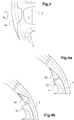
- the locking means 40, 40 ' as shown in figure 4a and 4b , comprise a push button 40, 40 'associated with each opposite end 4a, 4b of the complementary portion 4.
- the locking means 40, 40' comprise two push buttons 40, 40 '.
- Each push button 40, 40 ' is mounted on the complementary portion 4, so as to be able to switch from a rest position, with reference to the figure 4a , in which it protrudes from the complementary portion 4a, 4b, towards a retracted position, with reference to the figure 4b , in which the push button 40, 40 'is entered into the thickness of the complementary portion 4.
- the push button 40, 40 'in its rest position forms a stop against a free end 31, 32 of the main portion 3.
- the push button 40,40' maintains the complementary portion 4 in the driving position.
- the complementary portion 4 When the complementary portion 4 reaches the retracted position, it can be held by a locking member, preventing it from pivoting freely. For example, a push-button locking (type "push-pull" in English). In the retracted position, the handwheel is blocked in zone 4a, 4b by a valve system. For unlocking, the complementary portion 4 is pushed towards the front of the vehicle. The valves are unlocked during this rotational movement of low amplitude. The return spring then makes it possible to return the complementary portion 4 to its driving position.
- a locking member For example, a push-button locking (type "push-pull" in English).
- the handwheel In the retracted position, the handwheel is blocked in zone 4a, 4b by a valve system.
- the complementary portion 4 In the retracted position, the handwheel is blocked in zone 4a, 4b by a valve system.
- the valves are unlocked during this rotational movement of low amplitude.
- the return spring then makes it possible to return
- the flywheel 1 further comprises return means, not shown, here a return spring, for example a helical spring, for example a torsion spring, installed at one end on the main portion 3 or on a spoke 5, 5 'among the diametrically opposed spokes 5, 5' and on the other hand to the complementary portion 4 so that it is capable of automatically returning from the retracted position to the driving position.
- a return spring for example a helical spring, for example a torsion spring
- the return means may also comprise a diametrically opposed radius return spring 5, 5 'so that the return is exerted on each opposite end 4a, 4b of the complementary portion 4.
- an unlocking member for example a push button, or an electrical control, not shown, enables the locking of the complementary portion 4 to be unlocked in the retracted position so as to allow the return of the complementary portion 4. by the return spring from the retracted position to the driving position.
Landscapes
- Engineering & Computer Science (AREA)
- Chemical & Material Sciences (AREA)
- Combustion & Propulsion (AREA)
- Transportation (AREA)
- Mechanical Engineering (AREA)
- Steering Controls (AREA)
- Arrangement Or Mounting Of Propulsion Units For Vehicles (AREA)
Claims (7)
- Lenkrad (1) für ein Kraftfahrzeug, umfassend eine Nabe (2), die eine Drehachse definiert, einen im Wesentlichen kreisbogenförmigen Hauptabschnitt (3), der mit der Nabe (2) fest verbunden ist, und einen bogenförmigen komplementären Abschnitt (4), der mit dem Hauptabschnitt (3) fest verbunden ist, wobei der bogenförmige komplementäre Abschnitt (4) zwei entgegengesetzte Enden (4a, 4b) aufweist, die jeweils drehbar an dem bogenförmigen Hauptabschnitt (3) montiert sind, im Wesentlichen diametral entgegengesetzt;wobei der Hauptabschnitt (3) zwei freie Enden (3a, 3b) definiert, wobei die beiden entgegengesetzten Enden (4a, 4b) jeweils drehbar an den beiden freien Enden (3a, 3b) montiert sind, so dass der bogenförmige komplementäre Abschnitt (4) aus einer Fahrposition, in welcher der bogenförmige Hauptabschnitt (3) und der bogenförmige komplementäre Abschnitt (4) eine im Wesentlichen torische konvexe Form definieren, in eine eingeklappte Position schwenken kann, in welcher der bogenförmige komplementäre Abschnitt (4) in Bezug auf die Fahrposition um 180° geschwenkt ist,dadurch gekennzeichnet, dass sich der komplementäre Abschnitt (4) in der eingeklappten Position in derselben Ebene wie der Hauptabschnitt (3) erstreckt und Letzteren dabei umgibt;wobei das Lenkrad Arretierungsmittel (40, 40') umfasst, die geeignet sind, den bogenförmigen komplementären Abschnitt (4) in der Fahrposition zu arretieren; undwobei die Arretierungsmittel (40, 40') mindestens eine Drucktaste (40, 40') umfassen, die an dem bogenförmigen komplementären Abschnitt (4) angebracht ist.
- Lenkrad (1) nach Anspruch 1, dadurch gekennzeichnet, dass der bogenförmige komplementäre Abschnitt (4) im Wesentlichen die gleiche Länge wie der Hauptabschnitt (3) aufweist.
- Lenkrad (1) nach einem der vorhergehenden Ansprüche, dadurch gekennzeichnet, dass es Rückstellmittel zum Zurückstellen des komplementären Abschnitts (4) in die Fahrposition umfasst.
- Lenkrad (1) nach Anspruch 3, dadurch gekennzeichnet, dass die Rückstellmittel eine Rückstellfeder umfassen.
- Lenkrad (1) nach Anspruch 4, dadurch gekennzeichnet, dass die Rückstellfeder zum einen mit dem Hauptabschnitt (3) und zum anderen mit dem bogenförmigen komplementären Abschnitt (4) fest verbunden ist.
- Lenkrad (1) nach einem der vorhergehenden Ansprüche, dadurch gekennzeichnet, dass es zwei diametral entgegengesetzte Speichen (5, 5') umfasst, die sich jeweils zwischen der Nabe (2) und dem Hauptabschnitt (3) erstrecken, wobei der bogenförmige komplementäre Abschnitt (4) in der Nähe der beiden Speichen (5, 5') drehbar am Hauptabschnitt (3) angebracht ist.
- Lenkrad (1) nach Anspruch 6, dadurch gekennzeichnet, dass der Hauptabschnitt einen geschlossenen Teil (30) aufweist, der bis zu den beiden diametral entgegengesetzten Speichen (5, 5') reicht, und zwei freie Enden (31, 32), die sich jeweils von dem geschlossen Teil (30) aus entgegengesetzt zu den diametral entgegengesetzten (5, 5') Speichen (5, 5') erstrecken.
Applications Claiming Priority (2)
| Application Number | Priority Date | Filing Date | Title |
|---|---|---|---|
| FR1660030A FR3057533B1 (fr) | 2016-10-17 | 2016-10-17 | Volant pour vehicule automobile autonome. |
| PCT/FR2017/052829 WO2018073518A1 (fr) | 2016-10-17 | 2017-10-16 | Volant pour véhicule automobile autonome |
Publications (2)
| Publication Number | Publication Date |
|---|---|
| EP3526100A1 EP3526100A1 (de) | 2019-08-21 |
| EP3526100B1 true EP3526100B1 (de) | 2021-09-01 |
Family
ID=57485778
Family Applications (1)
| Application Number | Title | Priority Date | Filing Date |
|---|---|---|---|
| EP17792129.3A Active EP3526100B1 (de) | 2016-10-17 | 2017-10-16 | Lenkradanordnung für ein autonomes kraftfahrzeug |
Country Status (6)
| Country | Link |
|---|---|
| US (1) | US11247712B2 (de) |
| EP (1) | EP3526100B1 (de) |
| JP (1) | JP6717427B2 (de) |
| CN (1) | CN110198883B (de) |
| FR (1) | FR3057533B1 (de) |
| WO (1) | WO2018073518A1 (de) |
Families Citing this family (6)
| Publication number | Priority date | Publication date | Assignee | Title |
|---|---|---|---|---|
| FR3091511B1 (fr) * | 2019-01-04 | 2020-12-11 | Faurecia Interieur Ind | Volant de direction et panneau de garnissage comprenant un tel volant |
| US10562558B1 (en) * | 2019-04-09 | 2020-02-18 | Ford Global Technologies, Llc | Foldable steering wheel system |
| US11061401B2 (en) | 2019-10-29 | 2021-07-13 | Ford Global Technologies, Llc | Stowable steering wheel for autonomous vehicles |
| FR3114562B1 (fr) * | 2020-09-29 | 2023-12-01 | Autoliv Dev | Volant de véhicule |
| CN114684243B (zh) * | 2022-02-24 | 2023-01-13 | 智己汽车科技有限公司 | 一种方向盘及具备该方向盘的车辆 |
| KR102713421B1 (ko) * | 2022-04-06 | 2024-10-07 | 유승구 | 중장비용 조향 핸들유닛 |
Family Cites Families (16)
| Publication number | Priority date | Publication date | Assignee | Title |
|---|---|---|---|---|
| US1002663A (en) * | 1911-04-13 | 1911-09-05 | William P Fest Jr | Steering-wheel for autovehicles. |
| US1459957A (en) * | 1922-01-10 | 1923-06-26 | Fredrick B Merritt | Folding steering wheel |
| US1847209A (en) * | 1930-01-11 | 1932-03-01 | Jr Andre Bolinas | Folding steering wheel and lock |
| US2326131A (en) * | 1942-04-23 | 1943-08-10 | Eschelbacher Emanuel | Clear vision steering wheel |
| JPS571760U (de) * | 1980-06-05 | 1982-01-06 | ||
| JPS57142674U (de) * | 1981-03-03 | 1982-09-07 | ||
| JPS57142673U (de) * | 1981-03-04 | 1982-09-07 | ||
| JPS5964368U (ja) * | 1982-10-25 | 1984-04-27 | トヨタ自動車株式会社 | ステアリングホイ−ル |
| JPS6047670U (ja) * | 1983-09-09 | 1985-04-03 | ヤンマー農機株式会社 | トラクタ−等におけるハンドル装置 |
| JPH0236780Y2 (de) * | 1985-06-17 | 1990-10-05 | ||
| DE10316350A1 (de) * | 2003-04-10 | 2004-10-28 | Bayerische Motoren Werke Ag | Lenkrad mit einem im Durchmesser veränderbaren Lenkradkranz |
| US20070295151A1 (en) * | 2006-05-16 | 2007-12-27 | Boris Kentor | Steering wheel having pivoting rim |
| JP4293248B2 (ja) * | 2007-03-02 | 2009-07-08 | トヨタ自動車株式会社 | 車両用ステアリングシステム |
| US20160325662A1 (en) * | 2015-05-04 | 2016-11-10 | Steering Solutions Ip Holding Corporation | Steering wheel with integral tray table |
| US20180154921A1 (en) * | 2016-12-06 | 2018-06-07 | Ford Global Technologies, Llc | Folding steering wheel |
| US10562558B1 (en) * | 2019-04-09 | 2020-02-18 | Ford Global Technologies, Llc | Foldable steering wheel system |
-
2016
- 2016-10-17 FR FR1660030A patent/FR3057533B1/fr not_active Expired - Fee Related
-
2017
- 2017-10-16 US US16/340,854 patent/US11247712B2/en active Active
- 2017-10-16 EP EP17792129.3A patent/EP3526100B1/de active Active
- 2017-10-16 CN CN201780063807.1A patent/CN110198883B/zh active Active
- 2017-10-16 WO PCT/FR2017/052829 patent/WO2018073518A1/fr not_active Ceased
- 2017-10-16 JP JP2019518054A patent/JP6717427B2/ja active Active
Also Published As
| Publication number | Publication date |
|---|---|
| CN110198883A (zh) | 2019-09-03 |
| EP3526100A1 (de) | 2019-08-21 |
| US20210179160A1 (en) | 2021-06-17 |
| JP6717427B2 (ja) | 2020-07-01 |
| WO2018073518A1 (fr) | 2018-04-26 |
| US11247712B2 (en) | 2022-02-15 |
| FR3057533B1 (fr) | 2021-11-05 |
| FR3057533A1 (fr) | 2018-04-20 |
| JP2019531223A (ja) | 2019-10-31 |
| CN110198883B (zh) | 2022-05-10 |
Similar Documents
| Publication | Publication Date | Title |
|---|---|---|
| EP3526100B1 (de) | Lenkradanordnung für ein autonomes kraftfahrzeug | |
| EP2616616B1 (de) | Kraftfahrzeugsgriff mit einem trägheitskörper und einer sicherung | |
| WO2016091642A1 (fr) | Mécanisme de colonne de direction ajustable en profondeur à butée escamotable | |
| WO2018073526A1 (fr) | Volant pour véhicule automobile autonome. | |
| FR3108566A1 (fr) | Système de redressement réactif et dissipatif d’un siège de véhicule | |
| FR3025161A1 (fr) | Mecanisme de colonne de direction ajustable a verrou antivol | |
| EP2072327B1 (de) | Freigabeeinrichtung des Gepäckladeraums eines Kraftfahrzeugs | |
| EP0466534A1 (de) | Handbremshebel, insbesondere für Kraftfahrzeuge | |
| EP3041715B1 (de) | Diebstahlschutzvorrichtung für die lenksäule eines kraftfahrzeugs | |
| EP4594161A1 (de) | Fahrzeuglenkvorrichtung mit einer mobilen struktur und einer vorrichtung zum verriegeln der mobilen struktur | |
| FR3022510A1 (fr) | Ensemble interieur de vehicule, comportant une tablette | |
| EP2400203B1 (de) | Halterungsvorrichtung für tragbares Gerät für Kraftfahrzeuge, die mit einer halbkugelförmigen Rollenverbindung ausgestattet ist | |
| EP1454802B1 (de) | Lenkradmontierter Luftsack | |
| FR3141670A1 (fr) | Colonne de direction munie d’un verrou | |
| FR2949722A1 (fr) | Dispositif de support rabattable pour une face avant d'une porte d'un espace de rangement d'un tableau de bord de vehicule | |
| FR2963917A1 (fr) | Vehicule comportant un dispositif de blocage antivol des roues directrices | |
| FR2954245A1 (fr) | Dispositif de maintien d'un appareil electronique comprenant un bouton d'actionnement | |
| EP3113973B1 (de) | Entkuppelbare gelenkanordnung für einen kraftfahrzeugsitz | |
| EP1225077B1 (de) | Schalthebelvorrichtung für Kraftfahrzeugschaltgetriebe | |
| FR3092529A1 (fr) | Ensemble comprenant un dispositif d’affichage déplaçable en rotation autour d’une colonne de direction | |
| FR2889142A1 (fr) | Dispositif antivol permettant de commander le verrouillage d'une colonne de direction d'un vehicule automobile | |
| EP1571020B1 (de) | Steuerungsvorrichtung, insbesondere für eine Lüftungs-, Heizung- oder Klimaanlage, mit einer Krafthilfeeinrichtung | |
| FR2923194A1 (fr) | Dispositif de ceinture de securite equipe d'un systeme d'aide a la prehension | |
| EP3187812B1 (de) | Mechanische drehsteuerung eines turms mit manuell betätigbaren notdrehsteuermittel | |
| EP2870026B1 (de) | Vorrichtung zum zurückneigen eines sitzes |
Legal Events
| Date | Code | Title | Description |
|---|---|---|---|
| STAA | Information on the status of an ep patent application or granted ep patent |
Free format text: STATUS: UNKNOWN |
|
| STAA | Information on the status of an ep patent application or granted ep patent |
Free format text: STATUS: THE INTERNATIONAL PUBLICATION HAS BEEN MADE |
|
| PUAI | Public reference made under article 153(3) epc to a published international application that has entered the european phase |
Free format text: ORIGINAL CODE: 0009012 |
|
| STAA | Information on the status of an ep patent application or granted ep patent |
Free format text: STATUS: REQUEST FOR EXAMINATION WAS MADE |
|
| 17P | Request for examination filed |
Effective date: 20190408 |
|
| AK | Designated contracting states |
Kind code of ref document: A1 Designated state(s): AL AT BE BG CH CY CZ DE DK EE ES FI FR GB GR HR HU IE IS IT LI LT LU LV MC MK MT NL NO PL PT RO RS SE SI SK SM TR |
|
| AX | Request for extension of the european patent |
Extension state: BA ME |
|
| DAV | Request for validation of the european patent (deleted) | ||
| DAX | Request for extension of the european patent (deleted) | ||
| STAA | Information on the status of an ep patent application or granted ep patent |
Free format text: STATUS: EXAMINATION IS IN PROGRESS |
|
| 17Q | First examination report despatched |
Effective date: 20200214 |
|
| GRAP | Despatch of communication of intention to grant a patent |
Free format text: ORIGINAL CODE: EPIDOSNIGR1 |
|
| STAA | Information on the status of an ep patent application or granted ep patent |
Free format text: STATUS: GRANT OF PATENT IS INTENDED |
|
| INTG | Intention to grant announced |
Effective date: 20210430 |
|
| GRAS | Grant fee paid |
Free format text: ORIGINAL CODE: EPIDOSNIGR3 |
|
| GRAA | (expected) grant |
Free format text: ORIGINAL CODE: 0009210 |
|
| STAA | Information on the status of an ep patent application or granted ep patent |
Free format text: STATUS: THE PATENT HAS BEEN GRANTED |
|
| AK | Designated contracting states |
Kind code of ref document: B1 Designated state(s): AL AT BE BG CH CY CZ DE DK EE ES FI FR GB GR HR HU IE IS IT LI LT LU LV MC MK MT NL NO PL PT RO RS SE SI SK SM TR |
|
| REG | Reference to a national code |
Ref country code: GB Ref legal event code: FG4D Free format text: NOT ENGLISH |
|
| REG | Reference to a national code |
Ref country code: CH Ref legal event code: EP Ref country code: AT Ref legal event code: REF Ref document number: 1425950 Country of ref document: AT Kind code of ref document: T Effective date: 20210915 |
|
| REG | Reference to a national code |
Ref country code: DE Ref legal event code: R096 Ref document number: 602017045285 Country of ref document: DE |
|
| REG | Reference to a national code |
Ref country code: IE Ref legal event code: FG4D Free format text: LANGUAGE OF EP DOCUMENT: FRENCH |
|
| REG | Reference to a national code |
Ref country code: LT Ref legal event code: MG9D |
|
| REG | Reference to a national code |
Ref country code: NL Ref legal event code: MP Effective date: 20210901 |
|
| PG25 | Lapsed in a contracting state [announced via postgrant information from national office to epo] |
Ref country code: RS Free format text: LAPSE BECAUSE OF FAILURE TO SUBMIT A TRANSLATION OF THE DESCRIPTION OR TO PAY THE FEE WITHIN THE PRESCRIBED TIME-LIMIT Effective date: 20210901 Ref country code: SE Free format text: LAPSE BECAUSE OF FAILURE TO SUBMIT A TRANSLATION OF THE DESCRIPTION OR TO PAY THE FEE WITHIN THE PRESCRIBED TIME-LIMIT Effective date: 20210901 Ref country code: HR Free format text: LAPSE BECAUSE OF FAILURE TO SUBMIT A TRANSLATION OF THE DESCRIPTION OR TO PAY THE FEE WITHIN THE PRESCRIBED TIME-LIMIT Effective date: 20210901 Ref country code: LT Free format text: LAPSE BECAUSE OF FAILURE TO SUBMIT A TRANSLATION OF THE DESCRIPTION OR TO PAY THE FEE WITHIN THE PRESCRIBED TIME-LIMIT Effective date: 20210901 Ref country code: BG Free format text: LAPSE BECAUSE OF FAILURE TO SUBMIT A TRANSLATION OF THE DESCRIPTION OR TO PAY THE FEE WITHIN THE PRESCRIBED TIME-LIMIT Effective date: 20211201 Ref country code: NO Free format text: LAPSE BECAUSE OF FAILURE TO SUBMIT A TRANSLATION OF THE DESCRIPTION OR TO PAY THE FEE WITHIN THE PRESCRIBED TIME-LIMIT Effective date: 20211201 Ref country code: FI Free format text: LAPSE BECAUSE OF FAILURE TO SUBMIT A TRANSLATION OF THE DESCRIPTION OR TO PAY THE FEE WITHIN THE PRESCRIBED TIME-LIMIT Effective date: 20210901 Ref country code: ES Free format text: LAPSE BECAUSE OF FAILURE TO SUBMIT A TRANSLATION OF THE DESCRIPTION OR TO PAY THE FEE WITHIN THE PRESCRIBED TIME-LIMIT Effective date: 20210901 |
|
| REG | Reference to a national code |
Ref country code: AT Ref legal event code: MK05 Ref document number: 1425950 Country of ref document: AT Kind code of ref document: T Effective date: 20210901 |
|
| PG25 | Lapsed in a contracting state [announced via postgrant information from national office to epo] |
Ref country code: PL Free format text: LAPSE BECAUSE OF FAILURE TO SUBMIT A TRANSLATION OF THE DESCRIPTION OR TO PAY THE FEE WITHIN THE PRESCRIBED TIME-LIMIT Effective date: 20210901 Ref country code: LV Free format text: LAPSE BECAUSE OF FAILURE TO SUBMIT A TRANSLATION OF THE DESCRIPTION OR TO PAY THE FEE WITHIN THE PRESCRIBED TIME-LIMIT Effective date: 20210901 Ref country code: GR Free format text: LAPSE BECAUSE OF FAILURE TO SUBMIT A TRANSLATION OF THE DESCRIPTION OR TO PAY THE FEE WITHIN THE PRESCRIBED TIME-LIMIT Effective date: 20211202 |
|
| RAP4 | Party data changed (patent owner data changed or rights of a patent transferred) |
Owner name: NISSAN MOTOR CO., LTD. Owner name: RENAULT S.A.S |
|
| PG25 | Lapsed in a contracting state [announced via postgrant information from national office to epo] |
Ref country code: AT Free format text: LAPSE BECAUSE OF FAILURE TO SUBMIT A TRANSLATION OF THE DESCRIPTION OR TO PAY THE FEE WITHIN THE PRESCRIBED TIME-LIMIT Effective date: 20210901 |
|
| REG | Reference to a national code |
Ref country code: CH Ref legal event code: PL |
|
| PG25 | Lapsed in a contracting state [announced via postgrant information from national office to epo] |
Ref country code: IS Free format text: LAPSE BECAUSE OF FAILURE TO SUBMIT A TRANSLATION OF THE DESCRIPTION OR TO PAY THE FEE WITHIN THE PRESCRIBED TIME-LIMIT Effective date: 20220101 Ref country code: SM Free format text: LAPSE BECAUSE OF FAILURE TO SUBMIT A TRANSLATION OF THE DESCRIPTION OR TO PAY THE FEE WITHIN THE PRESCRIBED TIME-LIMIT Effective date: 20210901 Ref country code: SK Free format text: LAPSE BECAUSE OF FAILURE TO SUBMIT A TRANSLATION OF THE DESCRIPTION OR TO PAY THE FEE WITHIN THE PRESCRIBED TIME-LIMIT Effective date: 20210901 Ref country code: RO Free format text: LAPSE BECAUSE OF FAILURE TO SUBMIT A TRANSLATION OF THE DESCRIPTION OR TO PAY THE FEE WITHIN THE PRESCRIBED TIME-LIMIT Effective date: 20210901 Ref country code: PT Free format text: LAPSE BECAUSE OF FAILURE TO SUBMIT A TRANSLATION OF THE DESCRIPTION OR TO PAY THE FEE WITHIN THE PRESCRIBED TIME-LIMIT Effective date: 20220103 Ref country code: NL Free format text: LAPSE BECAUSE OF FAILURE TO SUBMIT A TRANSLATION OF THE DESCRIPTION OR TO PAY THE FEE WITHIN THE PRESCRIBED TIME-LIMIT Effective date: 20210901 Ref country code: EE Free format text: LAPSE BECAUSE OF FAILURE TO SUBMIT A TRANSLATION OF THE DESCRIPTION OR TO PAY THE FEE WITHIN THE PRESCRIBED TIME-LIMIT Effective date: 20210901 Ref country code: CZ Free format text: LAPSE BECAUSE OF FAILURE TO SUBMIT A TRANSLATION OF THE DESCRIPTION OR TO PAY THE FEE WITHIN THE PRESCRIBED TIME-LIMIT Effective date: 20210901 Ref country code: AL Free format text: LAPSE BECAUSE OF FAILURE TO SUBMIT A TRANSLATION OF THE DESCRIPTION OR TO PAY THE FEE WITHIN THE PRESCRIBED TIME-LIMIT Effective date: 20210901 |
|
| REG | Reference to a national code |
Ref country code: DE Ref legal event code: R097 Ref document number: 602017045285 Country of ref document: DE |
|
| REG | Reference to a national code |
Ref country code: BE Ref legal event code: MM Effective date: 20211031 |
|
| PG25 | Lapsed in a contracting state [announced via postgrant information from national office to epo] |
Ref country code: MC Free format text: LAPSE BECAUSE OF FAILURE TO SUBMIT A TRANSLATION OF THE DESCRIPTION OR TO PAY THE FEE WITHIN THE PRESCRIBED TIME-LIMIT Effective date: 20210901 |
|
| PLBE | No opposition filed within time limit |
Free format text: ORIGINAL CODE: 0009261 |
|
| STAA | Information on the status of an ep patent application or granted ep patent |
Free format text: STATUS: NO OPPOSITION FILED WITHIN TIME LIMIT |
|
| RAP4 | Party data changed (patent owner data changed or rights of a patent transferred) |
Owner name: NISSAN MOTOR CO., LTD. Owner name: RENAULT S.A.S |
|
| PG25 | Lapsed in a contracting state [announced via postgrant information from national office to epo] |
Ref country code: LU Free format text: LAPSE BECAUSE OF NON-PAYMENT OF DUE FEES Effective date: 20211016 Ref country code: IT Free format text: LAPSE BECAUSE OF FAILURE TO SUBMIT A TRANSLATION OF THE DESCRIPTION OR TO PAY THE FEE WITHIN THE PRESCRIBED TIME-LIMIT Effective date: 20210901 Ref country code: DK Free format text: LAPSE BECAUSE OF FAILURE TO SUBMIT A TRANSLATION OF THE DESCRIPTION OR TO PAY THE FEE WITHIN THE PRESCRIBED TIME-LIMIT Effective date: 20210901 Ref country code: BE Free format text: LAPSE BECAUSE OF NON-PAYMENT OF DUE FEES Effective date: 20211031 |
|
| 26N | No opposition filed |
Effective date: 20220602 |
|
| PG25 | Lapsed in a contracting state [announced via postgrant information from national office to epo] |
Ref country code: SI Free format text: LAPSE BECAUSE OF FAILURE TO SUBMIT A TRANSLATION OF THE DESCRIPTION OR TO PAY THE FEE WITHIN THE PRESCRIBED TIME-LIMIT Effective date: 20210901 Ref country code: LI Free format text: LAPSE BECAUSE OF NON-PAYMENT OF DUE FEES Effective date: 20211031 Ref country code: CH Free format text: LAPSE BECAUSE OF NON-PAYMENT OF DUE FEES Effective date: 20211031 |
|
| PG25 | Lapsed in a contracting state [announced via postgrant information from national office to epo] |
Ref country code: IE Free format text: LAPSE BECAUSE OF NON-PAYMENT OF DUE FEES Effective date: 20211016 |
|
| PG25 | Lapsed in a contracting state [announced via postgrant information from national office to epo] |
Ref country code: CY Free format text: LAPSE BECAUSE OF FAILURE TO SUBMIT A TRANSLATION OF THE DESCRIPTION OR TO PAY THE FEE WITHIN THE PRESCRIBED TIME-LIMIT Effective date: 20210901 |
|
| PG25 | Lapsed in a contracting state [announced via postgrant information from national office to epo] |
Ref country code: HU Free format text: LAPSE BECAUSE OF FAILURE TO SUBMIT A TRANSLATION OF THE DESCRIPTION OR TO PAY THE FEE WITHIN THE PRESCRIBED TIME-LIMIT; INVALID AB INITIO Effective date: 20171016 |
|
| PG25 | Lapsed in a contracting state [announced via postgrant information from national office to epo] |
Ref country code: MK Free format text: LAPSE BECAUSE OF FAILURE TO SUBMIT A TRANSLATION OF THE DESCRIPTION OR TO PAY THE FEE WITHIN THE PRESCRIBED TIME-LIMIT Effective date: 20210901 |
|
| PG25 | Lapsed in a contracting state [announced via postgrant information from national office to epo] |
Ref country code: MT Free format text: LAPSE BECAUSE OF FAILURE TO SUBMIT A TRANSLATION OF THE DESCRIPTION OR TO PAY THE FEE WITHIN THE PRESCRIBED TIME-LIMIT Effective date: 20210901 |
|
| PG25 | Lapsed in a contracting state [announced via postgrant information from national office to epo] |
Ref country code: TR Free format text: LAPSE BECAUSE OF FAILURE TO SUBMIT A TRANSLATION OF THE DESCRIPTION OR TO PAY THE FEE WITHIN THE PRESCRIBED TIME-LIMIT Effective date: 20210901 |
|
| PGFP | Annual fee paid to national office [announced via postgrant information from national office to epo] |
Ref country code: DE Payment date: 20251021 Year of fee payment: 9 |
|
| PGFP | Annual fee paid to national office [announced via postgrant information from national office to epo] |
Ref country code: GB Payment date: 20251022 Year of fee payment: 9 |
|
| PGFP | Annual fee paid to national office [announced via postgrant information from national office to epo] |
Ref country code: FR Payment date: 20251030 Year of fee payment: 9 |