EP3526655B1 - Ensembles charnière à décalage d'axe - Google Patents
Ensembles charnière à décalage d'axe Download PDFInfo
- Publication number
- EP3526655B1 EP3526655B1 EP17895146.3A EP17895146A EP3526655B1 EP 3526655 B1 EP3526655 B1 EP 3526655B1 EP 17895146 A EP17895146 A EP 17895146A EP 3526655 B1 EP3526655 B1 EP 3526655B1
- Authority
- EP
- European Patent Office
- Prior art keywords
- cam
- protrusion
- axis
- rotation
- shaft
- Prior art date
- Legal status (The legal status is an assumption and is not a legal conclusion. Google has not performed a legal analysis and makes no representation as to the accuracy of the status listed.)
- Active
Links
Images




Classifications
-
- G—PHYSICS
- G06—COMPUTING OR CALCULATING; COUNTING
- G06F—ELECTRIC DIGITAL DATA PROCESSING
- G06F1/00—Details not covered by groups G06F3/00 - G06F13/00 and G06F21/00
- G06F1/16—Constructional details or arrangements
- G06F1/1613—Constructional details or arrangements for portable computers
- G06F1/1633—Constructional details or arrangements of portable computers not specific to the type of enclosures covered by groups G06F1/1615 - G06F1/1626
- G06F1/1675—Miscellaneous details related to the relative movement between the different enclosures or enclosure parts
- G06F1/1681—Details related solely to hinges
-
- G—PHYSICS
- G06—COMPUTING OR CALCULATING; COUNTING
- G06F—ELECTRIC DIGITAL DATA PROCESSING
- G06F1/00—Details not covered by groups G06F3/00 - G06F13/00 and G06F21/00
- G06F1/16—Constructional details or arrangements
- G06F1/1613—Constructional details or arrangements for portable computers
- G06F1/1615—Constructional details or arrangements for portable computers with several enclosures having relative motions, each enclosure supporting at least one I/O or computing function
- G06F1/1616—Constructional details or arrangements for portable computers with several enclosures having relative motions, each enclosure supporting at least one I/O or computing function with folding flat displays, e.g. laptop computers or notebooks having a clamshell configuration, with body parts pivoting to an open position around an axis parallel to the plane they define in closed position
-
- E—FIXED CONSTRUCTIONS
- E05—LOCKS; KEYS; WINDOW OR DOOR FITTINGS; SAFES
- E05D—HINGES OR SUSPENSION DEVICES FOR DOORS, WINDOWS OR WINGS
- E05D3/00—Hinges with pins
- E05D3/02—Hinges with pins with one pin
-
- E—FIXED CONSTRUCTIONS
- E05—LOCKS; KEYS; WINDOW OR DOOR FITTINGS; SAFES
- E05Y—INDEXING SCHEME ASSOCIATED WITH SUBCLASSES E05D AND E05F, RELATING TO CONSTRUCTION ELEMENTS, ELECTRIC CONTROL, POWER SUPPLY, POWER SIGNAL OR TRANSMISSION, USER INTERFACES, MOUNTING OR COUPLING, DETAILS, ACCESSORIES, AUXILIARY OPERATIONS NOT OTHERWISE PROVIDED FOR, APPLICATION THEREOF
- E05Y2999/00—Subject-matter not otherwise provided for in this subclass
Definitions
- Electronic devices such as laptop computers, mobile phones, and the like may include a base portion, a cover portion, and a hinge mounted between the base portion and the cover portion.
- the base portion may house a keyboard, a motherboard, and/or other components.
- the cover portion may house a display.
- the hinge may connect the cover portion to the base portion and allow the cover portion to rotate relative to the base portion.
- US 2011/0047751 A1 discloses a hinge having a first pivoting module and a second pivoting module.
- the first pivoting module has a connecting block with a bore, a first pivot shaft and a second pivot shaft mounted on two opposite sides of the connecting block, a first movable assembly mounted on one end of the first pivot shaft and having a first urged piece and a first movable piece tracing and urging against the first urged piece to drive the first pivot shaft to radially move, a second movable assembly mounted on one end of the second pivot shaft to operate in coordination with the first movable assembly and having a second urged piece and a second movable piece tracing and urging against the second urged piece to drive the second pivot shaft to radially move.
- the second pivoting module is pivotally mounted on the connecting block.
- US 2008/263827 A1 discloses a pivotal-axis changing hinge having a stationary leaf, a pivoting leaf, a pintle assembly and a cam.
- the pivoting leaf and the stationary leaf are respectively connected securely to a cover having a rear edge and a keyway and a base having an elongated gudgeon.
- a parabolic edge is formed at an edge near the elongated gudgeon.
- the pintle assembly is mounted through the keyway and pivotally through the elongated gudgeon to allow the leaves to pivot along a pivotal axis of the pintle assembly.
- the cam is mounted on the pintle assembly, rotates simultaneously with the pintle assembly and has a protrusion mounted slidably on the parabolic edge to move the pintle assembly and the cover perpendicularly away from the base when the cover is pivoting.
- Hinged electronic devices such as laptop computers and flip mobile phones, may include a base portion and a cover portion hinged about a pivot axis. In a closed position, the pivot axis is positioned even with the plane of contact between the base portion and the cover portion. Because of this geometry, the cover portion and the base portion cannot open 180° (e.g., as the cover portion (e.g., hinge up) may interfere with the base portion) and/or the hinge may protrude upward out of the plane.
- the hinge assembly may include a first member and a second member rotatably connected to the first member through a mounting portion.
- the mounting portion may include a first surface having a first protrusion and a second surface, opposite the first surface, having a second protrusion.
- the hinge assembly may include a first cam fixed to the first member and disposed adjacent to the first surface and a second cam fixed to the first member and disposed adjacent to the second surface.
- the first cam being engageable with the first protrusion to move the axis of rotation from a first position to a second position during opening of the second member.
- the second cam being engageable with the second protrusion to move the axis of rotation from the second position to the first position during closing of the second member.
- Examples described herein may provide the hinge assembly with 180° axis of rotation. Examples described herein may avoid the interference/ overlap between the cover portion and the base portion when cover portion opens to 180°, particularly, between 145° to 180°.
- FIG. 1 is a perspective view of an example hinge assembly 100.
- Hinge assembly 100 includes a first member 102, a second member 104 rotatably connected to first member 102 through a mounting portion 106,
- Mounting portion 106 includes a first surface 108 having a first protrusion 116.
- mounting portion 106 includes a second surface 110 opposite first surface 108 and having a second protrusion 118.
- first protrusion 116 may be formed at a top portion of first surface 108 and second protrusion 118 may be formed at a bottom portion of second surface 110.
- first protrusion 116 and second protrusion 118 may be circular and cylindrical in shape.
- Hinge assembly 100 includes a first cam 112 fixed to first member 102 and disposed adjacent to first surface 108. Also, hinge assembly 100 includes a second cam 114 fixed to first member 102 and disposed adjacent to second surface 110. In one example, first cam 112 and second cam 114 may have a non-uniform radius including a large diameter part and a small diameter part. First cam 112 and second cam 114 may be circular and include an oval exterior surface.
- first cam 112 and second cam 114 are engageable with first protrusion 116 and second protrusion 118, respectively, to shift an axis of rotation of second member 104.
- first cam 112 may abut and engage with first protrusion 116 to move/change the axis of rotation from a first position to a second position during opening of second member 104.
- second cam 114 may abut and engage with second protrusion 118 to move/change the axis of rotation from the second position to the first position (i.e., shifting the axis of rotation back to the original position in a folded state) during closing of second member 104.
- FIG. 2 is a perspective view of another example hinge assembly 200 for an electronic device.
- Hinge assembly 200 includes a include shaft 220, a first member 202 mounted on shaft 220, and a second member 204 pivotable with respect to first member 202.
- Shaft 220 is fixedly coupled to first member 202.
- shaft 220 may be fixed to first member 202 by means of a mounting flange.
- Second member 204 includes a mounting portion 206 rotatably mounted on shaft 220 such that second member 204 pivots with respect to first member 202.
- Mounting portion 206 includes a first surface 208 having a first protrusion 216. Further, mounting portion 206 includes a second surface 210 opposite first surface 208 and having a second protrusion 218. First protrusion 216 may be formed at a top portion of first surface 208 and second protrusion 218 may be formed at bottom portion of second surface 210.
- Hinge assembly 200 includes a first cam 212 fixedly mounted on shaft 220 and disposed adjacent to first surface 208. Further, hinge assembly 200 includes a second cam 214 fixedly mounted on shaft 220 and disposed adjacent to second surface 210.
- First cam 212 and second cam 214 may include an oval exterior surface.
- first cam 212 and second cam 214 may be fixedly coupled to shaft 220 such that the oval exterior surface may be disposed towards the bottom side.
- First cam 212 and second cam 214 may shift a longitudinal axis of hinge assembly 200 from a default first position to a second position and vice versa in response to a rotational movement of second member 204 as explained below.
- first cam 212 may abut and engage with first protrusion 216 to move an axis of rotation from a first position to a second position (e.g., by outwardly moving second member 204) during opening of second member 204.
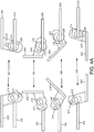
- first cam 212 may move the axis of rotation from the first position to the second position when an angle between first member 202 and second member 204 is in a range of 135° to 180° during opening of second member 204. Shifting the axis of rotation from the first position to the second position is explained in detail in FIG. 4A .
- second cam 214 may abut and engage with second protrusion 218 to move the axis of rotation from the second position to the first position (e.g., by inwardly moving second member 204) during closing of second member 204.
- second cam 214 may move the axis of rotation from the second position to the first position when the angle between first member 202 and second member 204 is in a range of 0° to 90° during closing of second member 204, Shifting the axis of rotation from the second position to the first position is explained in detail in FIG. 4B .
- FIG. 3A is a perspective view of an example electronic device 300 including a hinge 306, such as hinge assembly 100 or 200 shown in FiGs. 1 and 2 .
- Electronic device 300 includes a base portion 304 and a cover portion 302 connected to base portion 304 via hinge 306.
- Example electronic device 300 may be a computing system, for example, a laptop, a notebook, a sub-notebook, a mobile telephone, a personal gaming device, or other computing device with cover portion 302 closeable onto base portion 304.
- base portion 304 may house a keyboard, a battery, a touchpad, and so on.
- Cover portion 302 may house a display.
- Hinge 306 may allow cover portion 302 (e.g., display housing) to rotate in directions about rotational axis relative to base portion 304,
- FIG. 3B is the perspective view of example hinge 306, such as hinge assembly 200 of FIG. 2 depicting additional features.
- Hinge 306 includes first member 202 and second member 204.
- first member including a main body 222 and shaft 220 may be made up of a single-piece structure as shown in FIG. 1 .
- second member 204 may be rotatably mounted on first member 202 through mounting portion 206.
- first member may be made up of a two-piece structure, one being main body 222 and other being shaft 220.
- shaft 220 may be connected to an end of main body 222.
- shaft 220 may be fixed to main body 222 by means of a mounting flange 224.
- mounting portion 206 may be rotatably mounted on shaft 220.
- mounting portion 206 includes include a mounting hole 230 that is being formed through a center of mounting portion 206. Mounting hole 230 is non-circular and mounted through by shaft 220 to allow axis shifting of second member 204 during rotation of cover portion 302.
- mounting portion 206 includes a first surface 208 having first protrusion 216, and second surface 210 having second protrusion 218.
- First protrusion 216 may protrude from a top portion of first surface 208 and second protrusion 218 may protrude from a bottom portion of second surface 210.
- Hinge 306 includes first cam 212 fixed to first member 202/shaft 220 and disposed adjacent to first surface 208.
- hinge 306 includes include second cam 214 fixed to first member 202/shaft 220 and disposed adjacent to second surface 210.
- First cam 212 may include an oval exterior surface 226 and second cam 214 may include an oval exterior surface 228.
- first cam 212 and second cam 214 includes a through hole. Shaft 220 is inserted into the through hole such that first cam 212 and second cam 214 are disposed on either side of mounting portion 206. Further, first member 202 is secured to base portion 304 and second member 204 is secured to cover portion 302 such that cover portion 302 can be moved relative to base portion 304 in response to rotation of cover portion 302 about hinge 306.
- first cam 212 may abut and engage with first protrusion 216 to move the axis of rotation from a first position to a second position where cover portion 302 may not interfere with base portion 304.
- second cam 214 may abut and engage with second protrusion 218 to move the axis of rotation from the second position to the first position.
- first cam 212 and second cam 214 with respect to first protrusion 216 and second protrusion 218 is explained in detail in FIGs. 4A and 4B .
- FIG. 4A is an example operation of first cam 212 that abuts and engages with first protrusion 216 to move the axis of rotation from the first position to the second position during opening of second member 204.
- FIGs, 4A and 4B depict positions of first protrusion 216 and second protrusion 218 with respect to first cam 212 and second cam 214 during opening and closing of second member 204.
- second member 204 is in a closed position, In the closed position, first protrusion 216 may be located on first surface 208 at a position opposite oval exterior surface 226 of first cam 212 and second protrusion 218 may be located on second surface 210 at a position physically engaging with oval exterior surface 228 of second cam 214.
- first protrusion 216 when second member 204 is opened from 0° to 90°, an outer perimeter of first protrusion 216 may abut and engage with an outer perimeter of first cam 212 with the axis of rotation in the first position.
- the outer perimeter of first protrusion 216 when second member 204 is opened from 90° to 135°, the outer perimeter of first protrusion 216 may abut and engage with the outer perimeter of first cam 212 with the axis of rotation in the first position.
- the outer perimeter of first protrusion 216 when second member 204 is opened from 135° to 180°, the outer perimeter of first protrusion 216 may abut and engage with oval exterior surface 226 of first cam 212 and hence move the axis of rotation from the first position to the second position (e.g., as shown in FIG. 5 ).
- first protrusion 216 may physically engage with large diameter portion of first cam 212 and hence shift the axis of rotation by outwardly moving second member 204.
- first cam 212 may stay in place while the cam action of first cam 212 may drive cover portion 302 away from base portion 304.
- FIG. 4B is an example operation of second cam 214 that abuts and engages with second protrusion 218 to move the axis of rotation from the second position to the first position during closing of second member 204,
- second member 204 is in 180° open position.
- an outer perimeter of second protrusion 218 may abut and engage with an outer perimeter of second cam 214 with the axis of rotation in the second position.
- the outer perimeter of second protrusion 218 may abut and engage with the outer perimeter of second cam 214 with the axis of rotation in the second position.
- second protrusion 218 may abut and engage with oval exterior surface 228 of second cam 214 and hence move the axis of rotation from the second position to the first position, In this case, second protrusion 218 may physically engage with large diameter portion of second cam 214 and hence move the axis of rotation back to the first position.
- second cam 214 may stay in place while the cam action of second cam 214 may drive second member 204 to move from the second position to the first position.
- FIG. 5 is an example schematic 500 depicting a shift in the axis of rotation of second member 204 during opening of second member 204.
- FIG. 5 depicts base portion 304, cover portion 302, and a hinge 306 connecting cover portion 302 to base portion 304.
- the axis of rotation may be moved from a first position 502 to a second position 504 (e.g., in the direction indicated by an arrow) to avoid cover portion 302 interference with base portion 304.
Landscapes
- Engineering & Computer Science (AREA)
- Computer Hardware Design (AREA)
- Theoretical Computer Science (AREA)
- Physics & Mathematics (AREA)
- Human Computer Interaction (AREA)
- General Engineering & Computer Science (AREA)
- General Physics & Mathematics (AREA)
- Mathematical Physics (AREA)
- Pivots And Pivotal Connections (AREA)
- Telephone Set Structure (AREA)
Claims (6)
- Dispositif électronique (300) comprenant :une partie couvercle (302) ;une partie de base (304) ; etune charnière (306) reliant la partie couvercle (302) à la partie de base (304), la charnière (306) comprenant :un premier élément (102 ; 202) ;un arbre (220) faisant partie du premier élément (102 ; 202) ou étant fixé au premier élément (102 ; 202) ;un second élément (104 ; 204) pouvant pivoter par rapport au premier élément (102 ; 202) et comportant une partie de montage (106 ; 206) montée de manière rotative sur l'arbre (220), la partie de montage (106 ; 206) comprenant :un trou de montage non circulaire (230) à travers lequel s'étend l'arbre (220) ;une première surface (108 ; 208) ayant une première protubérance (116; 216) ; etune seconde surface (110 ; 210) opposée à la première surface (108 ; 208) et ayant une seconde protubérance (118 ; 218) ;une première came (112 ; 212) fixée à l'arbre (220) et disposée adjacente à la première surface (108 ; 208), l'arbre (220) étant inséré à travers un trou traversant dans la première came (112 ; 212) ; etune seconde came (114 ; 214) fixée à l'arbre (220) et disposée de manière adjacente à la seconde surface (110 ; 210), l'arbre (220) étant inséré à travers un trou traversant dans la seconde came (114 ; 214), la première came (112 ; 212) et la seconde came (114 ; 214) pouvant être mises en prise avec la première protubérance (116 ; 216) et la seconde protubérance (118 ; 218), respectivement, pour décaler un axe de rotation du second élément (104 ; 204),le premier élément (102 ; 202) étant relié à la partie de base (304) et le second élément (104 ; 204) étant relié à la partie couvercle (302) de telle sorte que la partie couvercle (302) est déplacée par rapport à la partie de base (304) en réponse à la rotation de la partie couvercle (302) autour de la charnière (306).
- Dispositif électronique (300) selon la revendication 1, dans lequel la première came (112 ; 212) peut être mise en prise avec la première protubérance (116 ; 216) pour déplacer l'axe de rotation d'une première position à une seconde position où la partie couvercle (302) n'interfère pas avec la partie de base (304) pendant l'ouverture de la partie couvercle (302), et la seconde came (114 ; 214) pouvant être mise en prise avec la seconde protubérance (118 ; 218) pour déplacer l'axe de rotation de la seconde position à la première position pendant la fermeture de la partie couvercle (302).
- Dispositif électronique (300) selon la revendication 1, dans lequel la première protubérance (116 ; 216) fait saillie depuis une partie supérieure de la première surface (108 ; 208) et la seconde protubérance (118 ; 218) fait saillie depuis une partie inférieure de la seconde surface (110 ; 210).
- Dispositif électronique (300) selon la revendication 1, dans lequel le premier élément (102 ; 202) comprend :un corps principal (222) ; etl'arbre (220) relié au corps principal (222), la partie de montage (106 ; 206) du second élément (104 ; 204) étant montée de manière rotative sur l'arbre (220).
- Dispositif électronique selon la revendication 1, dans lequel la première came (112 ; 212) est conçue pour déplacer l'axe de rotation de la première position à la seconde position lorsqu'un angle entre le premier élément (102 ; 202) et le second élément (104 ; 204) est dans une plage de 135 ° à 180 ° pendant l'ouverture du second élément (104 ; 204), et la première came (112 ; 212) comprenant une surface extérieure ovale (226).
- Dispositif électronique selon la revendication 1, dans lequel la seconde came (114 ; 214) est conçue pour déplacer l'axe de rotation de la seconde position à la première position lorsqu'un angle entre le premier élément (102 ; 202) et le second élément (104 ; 204) est dans une plage de 0 ° à 90 ° pendant la fermeture du second élément (104 ; 204), et la seconde came (114 ; 214) comprenant une surface extérieure ovale (228).
Applications Claiming Priority (1)
| Application Number | Priority Date | Filing Date | Title |
|---|---|---|---|
| PCT/US2017/016627 WO2018144025A1 (fr) | 2017-02-06 | 2017-02-06 | Ensembles charnière à décalage d'axe |
Publications (3)
| Publication Number | Publication Date |
|---|---|
| EP3526655A1 EP3526655A1 (fr) | 2019-08-21 |
| EP3526655A4 EP3526655A4 (fr) | 2020-05-27 |
| EP3526655B1 true EP3526655B1 (fr) | 2021-04-28 |
Family
ID=63039991
Family Applications (1)
| Application Number | Title | Priority Date | Filing Date |
|---|---|---|---|
| EP17895146.3A Active EP3526655B1 (fr) | 2017-02-06 | 2017-02-06 | Ensembles charnière à décalage d'axe |
Country Status (4)
| Country | Link |
|---|---|
| US (1) | US11327534B2 (fr) |
| EP (1) | EP3526655B1 (fr) |
| CN (1) | CN110023876A (fr) |
| WO (1) | WO2018144025A1 (fr) |
Families Citing this family (1)
| Publication number | Priority date | Publication date | Assignee | Title |
|---|---|---|---|---|
| US20220412397A1 (en) * | 2021-06-28 | 2022-12-29 | Ebn Technology Corp. | Device with adjusted pause-type hinge |
Family Cites Families (36)
| Publication number | Priority date | Publication date | Assignee | Title |
|---|---|---|---|---|
| US5201902A (en) * | 1991-06-06 | 1993-04-13 | Baer Austin R | Gear hinge with knuckle-type bearing |
| US6859980B2 (en) * | 2002-06-06 | 2005-03-01 | Austin R. Baer | Covered pinned hinge |
| JP3979601B2 (ja) * | 2003-11-12 | 2007-09-19 | 日本航空電子工業株式会社 | 電子機器のヒンジ装置 |
| JP2006233998A (ja) * | 2005-02-22 | 2006-09-07 | Kato Electrical Mach Co Ltd | 携帯機器のヒンジ装置及び携帯電話機 |
| TWI314036B (en) * | 2005-07-28 | 2009-08-21 | Sanyo Electric Co | Hinge mechanism of foldable machine and fordable machine with the same hinge mechanism |
| CN101169153A (zh) * | 2006-10-24 | 2008-04-30 | 鸿富锦精密工业(深圳)有限公司 | 铰链结构及应用该铰链结构的折叠式电子装置 |
| DE07831131T1 (de) * | 2006-11-06 | 2010-04-08 | Mitsubishi Steel Mfg. Co., Ltd. | Scharniermechanismus |
| US7621020B2 (en) * | 2007-04-30 | 2009-11-24 | Shin Zu Shing Co., Ltd. | Pivotal-axis changing hinge |
| US20100315773A1 (en) * | 2009-06-12 | 2010-12-16 | Hewlett-Packard Development Company, L.P. | Foot height adjustment system and method |
| US20110047751A1 (en) | 2009-09-03 | 2011-03-03 | Chia-Hsiang Chen | Hinge and an electronic device with the same |
| JP2011220397A (ja) | 2010-04-06 | 2011-11-04 | Nec Casio Mobile Communications Ltd | 携帯機器 |
| US8982542B2 (en) * | 2010-11-17 | 2015-03-17 | Microsoft Technology Licensing, Llc | Hinge mechanism for mobile electronic device |
| CN102619866A (zh) * | 2011-01-28 | 2012-08-01 | 鸿富锦精密工业(深圳)有限公司 | 铰链结构 |
| JP5801607B2 (ja) | 2011-05-31 | 2015-10-28 | スタッフ株式会社 | 電子機器 |
| KR20120134653A (ko) * | 2011-06-03 | 2012-12-12 | 삼성전자주식회사 | 휴대 장치의 이축 힌지 장치 및 그의 캠 유닛 |
| KR101856780B1 (ko) * | 2011-07-13 | 2018-05-10 | 삼성전자주식회사 | 휴대 단말기의 이축 힌지 장치에서 기어 캠 장착 장치 |
| KR101958185B1 (ko) * | 2011-12-14 | 2019-03-18 | 삼성전자주식회사 | 휴대 장치의 기어 힌지 장치 |
| US8687354B2 (en) | 2012-01-30 | 2014-04-01 | Lenovo (Singapore) Pte. Ltd. | Dual shaft hinge with angle timing shaft mechanism |
| KR101285799B1 (ko) * | 2012-02-03 | 2013-07-23 | 권성태 | 이동 단말기용 힌지장치 |
| KR101899502B1 (ko) * | 2012-05-31 | 2018-11-02 | 삼성전자주식회사 | 힌지장치 및 이를 구비한 컴퓨팅장치 |
| TWM464981U (zh) * | 2013-03-05 | 2013-11-01 | Jarllytec Co Ltd | 梢型卡鎖式雙軸樞紐器 |
| JP6197327B2 (ja) * | 2013-03-27 | 2017-09-20 | 富士通株式会社 | 電子機器 |
| US9009919B1 (en) * | 2013-11-22 | 2015-04-21 | Sinher Technology Inc. | Steady opening and closing double-axis hinge |
| KR102244807B1 (ko) * | 2014-03-07 | 2021-04-26 | 엘지디스플레이 주식회사 | 접이식 디스플레이 장치 |
| US9436230B2 (en) * | 2014-07-14 | 2016-09-06 | Lenovo (Singapore) Pte. Ltd. | Dynamic moveable hinge |
| KR102213812B1 (ko) * | 2014-07-30 | 2021-02-08 | 삼성전자주식회사 | 2축 힌지 및 이를 구비하는 전자장치 |
| US9423833B2 (en) * | 2014-09-03 | 2016-08-23 | Sony Corporation | Hinge structure with stand and keyboard device |
| US9625952B2 (en) * | 2014-09-10 | 2017-04-18 | Lenovo (Singapore) Pte. Ltd. | Hinge assemblies |
| TW201612430A (en) * | 2014-09-24 | 2016-04-01 | First Dome Corp | Transformable hinge structure |
| US10310551B2 (en) * | 2015-04-09 | 2019-06-04 | Samsung Electronics Co., Ltd. | Foldable device |
| US10365691B2 (en) * | 2015-04-09 | 2019-07-30 | Samsung Electronics Co., Ltd. | Foldable device |
| US9617770B1 (en) * | 2016-08-03 | 2017-04-11 | Leohab Enterprise Co., Ltd. | Double-hinge device |
| US10067530B2 (en) * | 2016-09-02 | 2018-09-04 | Microsoft Technology Licensing, Llc | Integrated multi-pivot hinge module |
| US10437293B2 (en) * | 2016-09-23 | 2019-10-08 | Microsoft Technology Licensing, Llc | Multi-axis hinge |
| TWM537244U (zh) * | 2016-09-26 | 2017-02-21 | Jarllytec Co Ltd | 省力型轉軸裝置 |
| TWI656433B (zh) * | 2017-02-08 | 2019-04-11 | 仁寶電腦工業股份有限公司 | 轉軸模組與應用其的電子裝置 |
-
2017
- 2017-02-06 EP EP17895146.3A patent/EP3526655B1/fr active Active
- 2017-02-06 CN CN201780074181.4A patent/CN110023876A/zh active Pending
- 2017-02-06 US US16/076,207 patent/US11327534B2/en active Active
- 2017-02-06 WO PCT/US2017/016627 patent/WO2018144025A1/fr not_active Ceased
Also Published As
| Publication number | Publication date |
|---|---|
| EP3526655A4 (fr) | 2020-05-27 |
| EP3526655A1 (fr) | 2019-08-21 |
| US11327534B2 (en) | 2022-05-10 |
| CN110023876A (zh) | 2019-07-16 |
| WO2018144025A1 (fr) | 2018-08-09 |
| US20210173448A1 (en) | 2021-06-10 |
Similar Documents
| Publication | Publication Date | Title |
|---|---|---|
| US7621020B2 (en) | Pivotal-axis changing hinge | |
| US7055218B2 (en) | Hinge | |
| KR101461548B1 (ko) | 개폐장치 | |
| US20110154613A1 (en) | Hinge | |
| EP2621149B1 (fr) | Dispositif d'ouverture/fermeture | |
| US20110047751A1 (en) | Hinge and an electronic device with the same | |
| US20100095486A1 (en) | Hinge assembly with restricting unit | |
| US8073505B2 (en) | Portable electronic apparatus with dual hinges | |
| US8453299B2 (en) | Connecting module and sliding mechanism for electronic device | |
| US7469449B2 (en) | Rotatable hinge | |
| US20090235487A1 (en) | Biaxial hinge device and mobile terminal device | |
| EP3526655B1 (fr) | Ensembles charnière à décalage d'axe | |
| KR100991463B1 (ko) | 휴대 단말기용 스윙식 덮개 개폐장치 | |
| US20110154615A1 (en) | Hinge | |
| US20220158326A1 (en) | Antenna disposition in computing devices | |
| US7559117B2 (en) | Dual-axis hinge | |
| US9436230B2 (en) | Dynamic moveable hinge | |
| US7661176B2 (en) | Hinge assembly | |
| KR100827607B1 (ko) | 휴대폰용 양방향 스윙 힌지 모듈 | |
| TWI727701B (zh) | 轉軸結構 | |
| US20100170063A1 (en) | Hinge and electronic device with hinge | |
| CN206257158U (zh) | 双轴式枢纽器 | |
| US7603749B2 (en) | Dual-axis hinge for a portable electronic device | |
| US20040098834A1 (en) | Hinge for a mobile phone | |
| CN202545554U (zh) | 翻盖结构及电子装置 |
Legal Events
| Date | Code | Title | Description |
|---|---|---|---|
| STAA | Information on the status of an ep patent application or granted ep patent |
Free format text: STATUS: THE INTERNATIONAL PUBLICATION HAS BEEN MADE |
|
| PUAI | Public reference made under article 153(3) epc to a published international application that has entered the european phase |
Free format text: ORIGINAL CODE: 0009012 |
|
| STAA | Information on the status of an ep patent application or granted ep patent |
Free format text: STATUS: REQUEST FOR EXAMINATION WAS MADE |
|
| 17P | Request for examination filed |
Effective date: 20190517 |
|
| AK | Designated contracting states |
Kind code of ref document: A1 Designated state(s): AL AT BE BG CH CY CZ DE DK EE ES FI FR GB GR HR HU IE IS IT LI LT LU LV MC MK MT NL NO PL PT RO RS SE SI SK SM TR |
|
| AX | Request for extension of the european patent |
Extension state: BA ME |
|
| RIN1 | Information on inventor provided before grant (corrected) |
Inventor name: WU, KUAN-TING Inventor name: LIN, KUN-HUNG Inventor name: CHEN, WEI-CHUNG |
|
| DAV | Request for validation of the european patent (deleted) | ||
| DAX | Request for extension of the european patent (deleted) | ||
| A4 | Supplementary search report drawn up and despatched |
Effective date: 20200430 |
|
| RIC1 | Information provided on ipc code assigned before grant |
Ipc: E05D 7/06 20060101ALI20200423BHEP Ipc: G06F 1/16 20060101AFI20200423BHEP |
|
| GRAP | Despatch of communication of intention to grant a patent |
Free format text: ORIGINAL CODE: EPIDOSNIGR1 |
|
| STAA | Information on the status of an ep patent application or granted ep patent |
Free format text: STATUS: GRANT OF PATENT IS INTENDED |
|
| INTG | Intention to grant announced |
Effective date: 20210125 |
|
| GRAS | Grant fee paid |
Free format text: ORIGINAL CODE: EPIDOSNIGR3 |
|
| GRAA | (expected) grant |
Free format text: ORIGINAL CODE: 0009210 |
|
| STAA | Information on the status of an ep patent application or granted ep patent |
Free format text: STATUS: THE PATENT HAS BEEN GRANTED |
|
| AK | Designated contracting states |
Kind code of ref document: B1 Designated state(s): AL AT BE BG CH CY CZ DE DK EE ES FI FR GB GR HR HU IE IS IT LI LT LU LV MC MK MT NL NO PL PT RO RS SE SI SK SM TR |
|
| REG | Reference to a national code |
Ref country code: GB Ref legal event code: FG4D |
|
| REG | Reference to a national code |
Ref country code: CH Ref legal event code: EP |
|
| REG | Reference to a national code |
Ref country code: AT Ref legal event code: REF Ref document number: 1387816 Country of ref document: AT Kind code of ref document: T Effective date: 20210515 |
|
| REG | Reference to a national code |
Ref country code: DE Ref legal event code: R096 Ref document number: 602017037862 Country of ref document: DE |
|
| REG | Reference to a national code |
Ref country code: IE Ref legal event code: FG4D |
|
| REG | Reference to a national code |
Ref country code: LT Ref legal event code: MG9D |
|
| REG | Reference to a national code |
Ref country code: AT Ref legal event code: MK05 Ref document number: 1387816 Country of ref document: AT Kind code of ref document: T Effective date: 20210428 |
|
| PG25 | Lapsed in a contracting state [announced via postgrant information from national office to epo] |
Ref country code: HR Free format text: LAPSE BECAUSE OF FAILURE TO SUBMIT A TRANSLATION OF THE DESCRIPTION OR TO PAY THE FEE WITHIN THE PRESCRIBED TIME-LIMIT Effective date: 20210428 Ref country code: AT Free format text: LAPSE BECAUSE OF FAILURE TO SUBMIT A TRANSLATION OF THE DESCRIPTION OR TO PAY THE FEE WITHIN THE PRESCRIBED TIME-LIMIT Effective date: 20210428 Ref country code: BG Free format text: LAPSE BECAUSE OF FAILURE TO SUBMIT A TRANSLATION OF THE DESCRIPTION OR TO PAY THE FEE WITHIN THE PRESCRIBED TIME-LIMIT Effective date: 20210728 Ref country code: NL Free format text: LAPSE BECAUSE OF FAILURE TO SUBMIT A TRANSLATION OF THE DESCRIPTION OR TO PAY THE FEE WITHIN THE PRESCRIBED TIME-LIMIT Effective date: 20210428 Ref country code: LT Free format text: LAPSE BECAUSE OF FAILURE TO SUBMIT A TRANSLATION OF THE DESCRIPTION OR TO PAY THE FEE WITHIN THE PRESCRIBED TIME-LIMIT Effective date: 20210428 Ref country code: FI Free format text: LAPSE BECAUSE OF FAILURE TO SUBMIT A TRANSLATION OF THE DESCRIPTION OR TO PAY THE FEE WITHIN THE PRESCRIBED TIME-LIMIT Effective date: 20210428 |
|
| PG25 | Lapsed in a contracting state [announced via postgrant information from national office to epo] |
Ref country code: IS Free format text: LAPSE BECAUSE OF FAILURE TO SUBMIT A TRANSLATION OF THE DESCRIPTION OR TO PAY THE FEE WITHIN THE PRESCRIBED TIME-LIMIT Effective date: 20210828 Ref country code: GR Free format text: LAPSE BECAUSE OF FAILURE TO SUBMIT A TRANSLATION OF THE DESCRIPTION OR TO PAY THE FEE WITHIN THE PRESCRIBED TIME-LIMIT Effective date: 20210729 Ref country code: PL Free format text: LAPSE BECAUSE OF FAILURE TO SUBMIT A TRANSLATION OF THE DESCRIPTION OR TO PAY THE FEE WITHIN THE PRESCRIBED TIME-LIMIT Effective date: 20210428 Ref country code: PT Free format text: LAPSE BECAUSE OF FAILURE TO SUBMIT A TRANSLATION OF THE DESCRIPTION OR TO PAY THE FEE WITHIN THE PRESCRIBED TIME-LIMIT Effective date: 20210830 Ref country code: LV Free format text: LAPSE BECAUSE OF FAILURE TO SUBMIT A TRANSLATION OF THE DESCRIPTION OR TO PAY THE FEE WITHIN THE PRESCRIBED TIME-LIMIT Effective date: 20210428 Ref country code: NO Free format text: LAPSE BECAUSE OF FAILURE TO SUBMIT A TRANSLATION OF THE DESCRIPTION OR TO PAY THE FEE WITHIN THE PRESCRIBED TIME-LIMIT Effective date: 20210728 Ref country code: SE Free format text: LAPSE BECAUSE OF FAILURE TO SUBMIT A TRANSLATION OF THE DESCRIPTION OR TO PAY THE FEE WITHIN THE PRESCRIBED TIME-LIMIT Effective date: 20210428 Ref country code: RS Free format text: LAPSE BECAUSE OF FAILURE TO SUBMIT A TRANSLATION OF THE DESCRIPTION OR TO PAY THE FEE WITHIN THE PRESCRIBED TIME-LIMIT Effective date: 20210428 |
|
| REG | Reference to a national code |
Ref country code: NL Ref legal event code: MP Effective date: 20210428 |
|
| PG25 | Lapsed in a contracting state [announced via postgrant information from national office to epo] |
Ref country code: ES Free format text: LAPSE BECAUSE OF FAILURE TO SUBMIT A TRANSLATION OF THE DESCRIPTION OR TO PAY THE FEE WITHIN THE PRESCRIBED TIME-LIMIT Effective date: 20210428 Ref country code: EE Free format text: LAPSE BECAUSE OF FAILURE TO SUBMIT A TRANSLATION OF THE DESCRIPTION OR TO PAY THE FEE WITHIN THE PRESCRIBED TIME-LIMIT Effective date: 20210428 Ref country code: SK Free format text: LAPSE BECAUSE OF FAILURE TO SUBMIT A TRANSLATION OF THE DESCRIPTION OR TO PAY THE FEE WITHIN THE PRESCRIBED TIME-LIMIT Effective date: 20210428 Ref country code: SM Free format text: LAPSE BECAUSE OF FAILURE TO SUBMIT A TRANSLATION OF THE DESCRIPTION OR TO PAY THE FEE WITHIN THE PRESCRIBED TIME-LIMIT Effective date: 20210428 Ref country code: CZ Free format text: LAPSE BECAUSE OF FAILURE TO SUBMIT A TRANSLATION OF THE DESCRIPTION OR TO PAY THE FEE WITHIN THE PRESCRIBED TIME-LIMIT Effective date: 20210428 Ref country code: DK Free format text: LAPSE BECAUSE OF FAILURE TO SUBMIT A TRANSLATION OF THE DESCRIPTION OR TO PAY THE FEE WITHIN THE PRESCRIBED TIME-LIMIT Effective date: 20210428 Ref country code: RO Free format text: LAPSE BECAUSE OF FAILURE TO SUBMIT A TRANSLATION OF THE DESCRIPTION OR TO PAY THE FEE WITHIN THE PRESCRIBED TIME-LIMIT Effective date: 20210428 |
|
| REG | Reference to a national code |
Ref country code: DE Ref legal event code: R097 Ref document number: 602017037862 Country of ref document: DE |
|
| PLBE | No opposition filed within time limit |
Free format text: ORIGINAL CODE: 0009261 |
|
| STAA | Information on the status of an ep patent application or granted ep patent |
Free format text: STATUS: NO OPPOSITION FILED WITHIN TIME LIMIT |
|
| 26N | No opposition filed |
Effective date: 20220131 |
|
| PGFP | Annual fee paid to national office [announced via postgrant information from national office to epo] |
Ref country code: GB Payment date: 20220119 Year of fee payment: 6 Ref country code: DE Payment date: 20220119 Year of fee payment: 6 |
|
| PG25 | Lapsed in a contracting state [announced via postgrant information from national office to epo] |
Ref country code: IS Free format text: LAPSE BECAUSE OF FAILURE TO SUBMIT A TRANSLATION OF THE DESCRIPTION OR TO PAY THE FEE WITHIN THE PRESCRIBED TIME-LIMIT Effective date: 20210828 Ref country code: AL Free format text: LAPSE BECAUSE OF FAILURE TO SUBMIT A TRANSLATION OF THE DESCRIPTION OR TO PAY THE FEE WITHIN THE PRESCRIBED TIME-LIMIT Effective date: 20210428 |
|
| PGFP | Annual fee paid to national office [announced via postgrant information from national office to epo] |
Ref country code: FR Payment date: 20220120 Year of fee payment: 6 |
|
| PG25 | Lapsed in a contracting state [announced via postgrant information from national office to epo] |
Ref country code: IT Free format text: LAPSE BECAUSE OF FAILURE TO SUBMIT A TRANSLATION OF THE DESCRIPTION OR TO PAY THE FEE WITHIN THE PRESCRIBED TIME-LIMIT Effective date: 20210428 |
|
| PG25 | Lapsed in a contracting state [announced via postgrant information from national office to epo] |
Ref country code: MC Free format text: LAPSE BECAUSE OF FAILURE TO SUBMIT A TRANSLATION OF THE DESCRIPTION OR TO PAY THE FEE WITHIN THE PRESCRIBED TIME-LIMIT Effective date: 20210428 |
|
| REG | Reference to a national code |
Ref country code: CH Ref legal event code: PL |
|
| REG | Reference to a national code |
Ref country code: BE Ref legal event code: MM Effective date: 20220228 |
|
| PG25 | Lapsed in a contracting state [announced via postgrant information from national office to epo] |
Ref country code: LU Free format text: LAPSE BECAUSE OF NON-PAYMENT OF DUE FEES Effective date: 20220206 |
|
| PG25 | Lapsed in a contracting state [announced via postgrant information from national office to epo] |
Ref country code: LI Free format text: LAPSE BECAUSE OF NON-PAYMENT OF DUE FEES Effective date: 20220228 Ref country code: IE Free format text: LAPSE BECAUSE OF NON-PAYMENT OF DUE FEES Effective date: 20220206 Ref country code: CH Free format text: LAPSE BECAUSE OF NON-PAYMENT OF DUE FEES Effective date: 20220228 |
|
| PG25 | Lapsed in a contracting state [announced via postgrant information from national office to epo] |
Ref country code: BE Free format text: LAPSE BECAUSE OF NON-PAYMENT OF DUE FEES Effective date: 20220228 |
|
| REG | Reference to a national code |
Ref country code: DE Ref legal event code: R119 Ref document number: 602017037862 Country of ref document: DE |
|
| GBPC | Gb: european patent ceased through non-payment of renewal fee |
Effective date: 20230206 |
|
| PG25 | Lapsed in a contracting state [announced via postgrant information from national office to epo] |
Ref country code: GB Free format text: LAPSE BECAUSE OF NON-PAYMENT OF DUE FEES Effective date: 20230206 |
|
| PG25 | Lapsed in a contracting state [announced via postgrant information from national office to epo] |
Ref country code: GB Free format text: LAPSE BECAUSE OF NON-PAYMENT OF DUE FEES Effective date: 20230206 Ref country code: FR Free format text: LAPSE BECAUSE OF NON-PAYMENT OF DUE FEES Effective date: 20230228 Ref country code: DE Free format text: LAPSE BECAUSE OF NON-PAYMENT OF DUE FEES Effective date: 20230901 |
|
| PG25 | Lapsed in a contracting state [announced via postgrant information from national office to epo] |
Ref country code: MK Free format text: LAPSE BECAUSE OF FAILURE TO SUBMIT A TRANSLATION OF THE DESCRIPTION OR TO PAY THE FEE WITHIN THE PRESCRIBED TIME-LIMIT Effective date: 20210428 Ref country code: CY Free format text: LAPSE BECAUSE OF FAILURE TO SUBMIT A TRANSLATION OF THE DESCRIPTION OR TO PAY THE FEE WITHIN THE PRESCRIBED TIME-LIMIT Effective date: 20210428 |
|
| PG25 | Lapsed in a contracting state [announced via postgrant information from national office to epo] |
Ref country code: HU Free format text: LAPSE BECAUSE OF FAILURE TO SUBMIT A TRANSLATION OF THE DESCRIPTION OR TO PAY THE FEE WITHIN THE PRESCRIBED TIME-LIMIT; INVALID AB INITIO Effective date: 20170206 |
|
| PG25 | Lapsed in a contracting state [announced via postgrant information from national office to epo] |
Ref country code: MT Free format text: LAPSE BECAUSE OF FAILURE TO SUBMIT A TRANSLATION OF THE DESCRIPTION OR TO PAY THE FEE WITHIN THE PRESCRIBED TIME-LIMIT Effective date: 20210428 |
|
| PG25 | Lapsed in a contracting state [announced via postgrant information from national office to epo] |
Ref country code: TR Free format text: LAPSE BECAUSE OF FAILURE TO SUBMIT A TRANSLATION OF THE DESCRIPTION OR TO PAY THE FEE WITHIN THE PRESCRIBED TIME-LIMIT Effective date: 20210428 |