EP3526867B1 - Presse-étoupe comprenant une bague collectrice sur passe-fil - Google Patents
Presse-étoupe comprenant une bague collectrice sur passe-fil Download PDFInfo
- Publication number
- EP3526867B1 EP3526867B1 EP17787349.4A EP17787349A EP3526867B1 EP 3526867 B1 EP3526867 B1 EP 3526867B1 EP 17787349 A EP17787349 A EP 17787349A EP 3526867 B1 EP3526867 B1 EP 3526867B1
- Authority
- EP
- European Patent Office
- Prior art keywords
- grommet
- cable gland
- gland
- cable
- adhesive
- Prior art date
- Legal status (The legal status is an assumption and is not a legal conclusion. Google has not performed a legal analysis and makes no representation as to the accuracy of the status listed.)
- Active
Links
Images

Classifications
-
- H—ELECTRICITY
- H02—GENERATION; CONVERSION OR DISTRIBUTION OF ELECTRIC POWER
- H02G—INSTALLATION OF ELECTRIC CABLES OR LINES, OR OF COMBINED OPTICAL AND ELECTRIC CABLES OR LINES
- H02G15/00—Cable fittings
- H02G15/02—Cable terminations
- H02G15/04—Cable-end sealings
- H02G15/043—Cable-end sealings with end caps, e.g. sleeve closed at one end
- H02G15/046—Cable-end sealings with end caps, e.g. sleeve closed at one end with bores or protruding portions allowing passage of cable conductors
-
- B—PERFORMING OPERATIONS; TRANSPORTING
- B61—RAILWAYS
- B61C—LOCOMOTIVES; MOTOR RAILCARS
- B61C17/00—Arrangement or disposition of parts; Details or accessories not otherwise provided for; Use of control gear and control systems
Definitions
- the present invention relates to a cable gland.
- multi-core, thick, relatively flexible cables which have to be tailored to bridge the distance are usually used for establishing power-supply and signaling connections between individual carriages and/or traction units and/or locomotives of a train. Said tailoring is usually difficult on account of problems of space. This is true particularly for the requisite cable glands with which the ends of the cable are inserted into the housings of the parts which are to be connected and are screwed there. A good adhesive between cable and grommets is fundamental to ensure fixation (strain relieve) and sealing of cables as used in various technical application.
- US2014090887A published on the 03.04.2015 by the same applicant, relates to a cable gland for a cable, comprising an outer shield, a cable sleeve enclosing the outer shield and an anti-kink grommet which is injection molded externally onto the cable sleeve and has stop means for the cable gland.
- the cable gland has a substantially hollow cylindrical electrically conductive cable gland body which is pushed from one side as far as the stop means over the anti-kink grommet and projects over the anti-kink grommet with the end opposite the stop means, and has a union nut which can be screwed on the cable gland body and is pushed from the other side as far as the stop means over the anti-kink grommet, and has an electrically conductive substantially hollow cylindrical contact ring which can be pushed over the cable in a contacting manner into the projecting end of the cable gland body and is designed for receiving and fastening the outer shielding of the cable with contact.
- US4797513A published on the 08.06.1989 by Yazaki Crop., relates to an improvement of noise prevention and waterproof effects and simultaneously wiring workability of a funnel-shaped grommet used for wiring a wire bundle or a cable through a panel, a sealing material is put into the grommet from above to fill a space between a small-diameter cylindrical portion of the grommet and the wire bundle and gaps between wires.
- the sealing material is a two-liquid polyurethane resin based bonding agent or a nitrile rubber based bonding agent.
- DE102006049689B3 published by Sumito Electric Bordnetze GmbH on the 27.02.2008, relates to a method involving pressing a lower tubular section of a nozzle on a wiring harness with its fixed wrapping by two semi-circular lining units.
- the units are removed according to the hardness of a sealing compound.
- the nozzle is lifted according to the compound hardness and the removal of the units such that the deformation of the section and a frustum-like section of the nozzle results from lifting set a position, in which diameter of the section corresponds to an upper tubular section.
- the diameter is set by the hardened compound within the section.
- US2001008330A published on the 19.07.2001 by Sumito Wiring Systems, relates to a sealing grommet that includes a grommet body with a sealant reservoir and a sealant drain portion.
- the grommet body has an outer peripheral wall, a panel engagement recess formed on the outer peripheral surface of the outer peripheral wall, and an inner peripheral wall extending inwardly of the outer peripheral wall and defining a wire harness insertion aperture inwardly thereof.
- the sealant reservoir is provided between the inner and outer peripheral walls, and is configured to temporarily store a sealant therein.
- the sealant drain portion is provided on the inner peripheral wall, and is configured to open upon deformation of the grommet body, thereby permitting the sealant to drain into the wire harness insertion aperture from the reservoir.
- the sealant can easily permeate between wires of the wire harness provided within the wire harness insertion aperture. Additionally, because the need for a sealant injection nozzle can be eliminated, a waterproof sealing operation can easily be carried out, even if the size of the sealing grommet is small.
- a sealing body surrounds and relieves the stress on the cable and is held firmly by a holder, for example two pressed-on, truncated-conical hollow edges in the plates which clamp on the sealing body around a thickened region.
- the cable sheath has been removed in the first section of the sealing body, and the section is filled with a sealing compound which completely surrounds the individual conductors and completely fills the space as far as the cable sheath. In consequence, the cable end is completely closed in a particularly simple manner with respect to air, moisture and water, and the cable is mechanically fixed at the same time.
- a grommet including a hollow shell, a hollow retaining section, and a hollow member, the shell having a shell opening at a first end and a reduced diameter opening at a second end, and in communication with the retaining section at the second end.
- the member is in communication with said retaining section.
- a filler opening is provided in the member wall, and filler walls extend from the member and form a filler inlet in communication with the filler opening.
- the filler inlet can receive the filler which flows through the filler opening into the member and surrounds at least one elongated, generally cylindrical object located within the member and the retaining section.
- US6488317B published by Avaya Technology Corp. on the 03.12.2002, discloses a strain relief including a main body having a bore therein for passage of a cable, wire, conduit, hose, or similar member therethrough.
- a flexible elastomeric grommet is located within the bore and extends substantially along an entire length of the main body.
- the grommet includes a cylindrical sidewall and a plurality of spaced-apart annular ribs extending radially inwardly from the sidewall.
- a plurality of annular grooves are located between the annular ribs.
- the annular ribs have inside diameters which progressively increase along a length of the grommet in order to accommodate cables of various diameters therethrough.
- a silicone gel may be located in the annular grooves to improve the seal between the gr
- US 2010/0062628 A1 published by UTILX CORPORATION on the 11. 03. 2010 discloses a cable termination connection to an apparatus. It includes a main body defining an inner cavity having first and second ends, the main body configured to receive a pressurized fluid, and the first end configured to receive at least a portion of the cable therein, and a first engagement mechanism configured to couple the main body to the cable, wherein the first engagement mechanism includes a first adhesive seal.
- FR2724780 A1 published on the 22. 03. 1996 discloses a support ring for electrical conductors intended for to be used for the partition feed-through and of the type formed a body through which the conductors pass, characterized in that that said body has a first sleeve opening out in a receptacle closed by a closing wall extended by a second sleeve (46) coaxial with the first sleeve, the conductors passing through the sleeves and, the receptacle having an injection hole a pasty, adhesive material that can harden.
- Cable glands known form the prior art are often difficult to apply in a reproducible manner. In addition they are labor intensive and do not provide constant results. It is an object of the invention to provide a cable gland which overcomes the problems of the prior art.
- a cable gland according to the invention comprises a grommet which is foreseen to be slipped on a cable from an end of the cable. When in position the grommet is attached to the cable by an adhesive. This takes place in that an inner space of the grommet arranged between an inner wall of the grommet and an outer wall of the cable is filled by an adhesive as described hereinafter in more detail. After the grommet is sufficiently fixed on the cable it is interconnected to a gland flange by which it is then interconnected e.g. to a housing. Good results are achieved if the grommet is fixed to the gland flange by a gland nut as described subsequent.
- the grommet comprises a tubular base body made from an elastic material and extending in an axial direction, hereinafter called cable gland axis, from a first outer end to a second outer end.
- the tubular base body has at least one flow channel, forming part of the inner space mentioned above, arranged on the inside between the first and the second outer end and extending in one or several steps in circumferential direction along an inner surface of the tubular base body.
- At least one filling hole extends from said flow channel radially outwards through the tubular base body. The filling hole is foreseen for filling the inner space of the tubular base body with an adhesive when arranged on a cable.
- a first circumferential sealing lip is arranged in the region of the first outer end and a second circumferential sealing lip is arranged in the region of the second outer end.
- the first and the second circumferential sealing lips are foreseen to seal the inner space of the tubular base body when mounted on a cable with respect to the cable.
- at least one of the circumferential sealing lips is foreseen to temporarily clamp the tubular base body of the grommet with respect to the cable to prevent unwanted displacing of the cable grommet when the adhesive cures.
- the grommet may comprise an annular shoulder extending from an outer surface of the tubular base body circumferentially in an outward direction.
- the at least one filling hole extends at least partially through the annular shoulder. If two filling holes are used, they are can be arranged over the circumference opposite from each other, so that the adhesive is more evenly distributed through the inner space to be filled.
- both sealing lips are placed at the region of the outer ends of the grommet facing away from the displacement. In that way, if the grommet is displaced in the direction of the displacement direction the sealing lips maintain a more abiding sealing effect during the movement.
- At least one of the circumferential sealing lips may comprise a venting cut-out allowing during filling of the inner space excessive air and/or excessive adhesive to be pushed out to support the filling of the inner space in the grommet with adhesive.
- the venting cut-out is preferably designed in a way that if pressure is built up in the grommet due to the filling with adhesive the sealing lip on which the venting cut-out is placed is slightly lifted in the region of the venting cut-out in order to allow excessive air or adhesive to be pushed out. After the venting process which causes the pressure again to fall, the sealing lip closes and tightly seals the grommet over the circumference.
- the form of the at least one flow channel may differ from variation to variation.
- the at least one flow channel has a form of an annular ring extending around the cable gland axis.
- the flow channel may comprise at least one helical section. If appropriate, combinations of different forms of flow channel geometries are possible, such as e.g. a combination of an annular flow channel with one or more multiple helix structured flow channels. If more than one flow channel is present the flow channels can intercross with each other e.g. forming a pattern.
- first locking means can be foreseen on the tubular base body which in mounted position interlock with second locking means arranged at the gland flange thereby prohibiting an unwanted angular displacement of the grommet in respect to gland flange.
- at least one first first locking means extends from the outer surface of the tubular body in form of a tooth foreseen to engage with at least one respective second locking means in form of key ways of the gland flange.
- the grommet may be made from one part, however, alternatively also a grommet comprising multiple parts that are assembled together to form in the assembled state a grommet according to the invention is possible. This may be advantageous in terms of manufacturing reasons and costs. Therefore, the grommet may e.g. comprise a front part and a rear part which are interconnectable with respect to each other in the direction of the cable gland axis. Subsequently, in the case of a front part and a rear part, the flow channel may comprises a front section arranged at the front part of the grommet and rear section arranged at the rear part of the grommet.
- both parts, front and rear part are glued and secured together more thoroughly if both parts have a section adjacent to the flow channel filled with adhesive.
- first locking means are present, the front part and the rear part of the grommet each have a first locking means which are aligned to one another.
- the adhesive is preferably pressed first through the at least one filling hole in the flow channel(s) distributing the adhesive over the circumference of the cable. If the flow channels are filled the pressure rises and the adhesive may consequently be pressed further between the remaining circumferential surfaces between the cable and the grommet until the sealing lips are reached.
- the sealing lips are hereby designed in way that the internal pressure built-up results in an enhanced sealing property of the seal to the outside environment. This can be achieved by a tilt angle directing to the inside.
- the grommet may be filled until excessive adhesive is pressed out through the venting cut-out, hence visually indicating, that the adhesive has traveled through the larger part of the available inner space and therefore optimally bonding the grommet to the cable.
- This effect is even more pronounced if the venting cut-out is placed not at the same circumferential position than the filling hole but at a position that has optimally a maximal possible angle to the filling hole, respective the adjacent filling holes. In that way the adhesive reaches the venting cut-out at a point when the adhesive has not only filled the space in an axial direction but also travel in the best case around the full circumference of the cable.
- a support fixture may be used during filling to prevent a deformation of the grommet during injection of the adhesive.
- the grommet is made preferably produced by injection molding of rubber type plastic material to form an elastically deformable grommet.
- good results can be achieved by using at least one material out of the group of the following materials: polyurethane, silicone, siliane modified polymers.
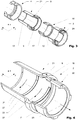
- FIG 1 and Figure 2 show a first variation of the invention according to claim 1.
- the grommet 2 is shown having a front and rear part 20, 21 which are both essentially tubular. From an outer surface 19 of the rear part 21 of the grommet 2 an annular shoulder 18 is extending in a radial direction in which a filling hole 9 is placed that is interconnected to a flow channel 7 and an inner space 10 of the grommet 2.
- the annular shaped flow channel 7 comprises a front section arranged at the front part 20 and rear section arranged at the rear part 21 of the grommet 2.
- a first circumferential sealing lip 12 is arranged on the front part 20 of the grommet 2 in the region of the first outer end 14 of the grommet 2.
- a second circumferential sealing lip 13 is arranged on the rear part 21 of the grommet 2 in the region of the second outer end 15. Both sealing lips 12, 13 seal the inner space 10 when the grommet is mounted on a cable with respect to the cable (not shown here).
- the second circumferential sealing lip 13 comprises one venting cut-out 16 which allows excessive air and/or excessive adhesive to be pushed out during filling of the grommet 2 with adhesive.
- the direction in which the individual sealing lips 12, 13 are facing is preferably chosen according to a displacement direction 26.
- the displacement direction 26 is the direction in which the grommet 2 is displaced while being filled with adhesive in the assembling process.
- the displacement has further the advantage, that the distribution of the adhesive is generally enhanced in the process since the adhesive is more evenly spread due to the friction between to the grommet 2 on one hand and the cable on the other hand.
- the first circumferential sealing lip 12 26 is placed at the region of the outer end 14 and is tilted inwards and away from the displacement direction.
- the second circumferential sealing lip 13 is also tilted away from the displacement direction 26 and is placed at the remaining outer end 15.
- the venting cut-out 16 is hereby placed on the sealing lip 13 that is facing away from the displacement direction 26.
- the front and the rear part 20, 21 both comprise multiple first locking means 17 which prohibit an angular displacement of the grommet 2 in respect to gland flange 3.
- the first locking means 17 extend from the outer surface 19 of the tubular body (formed by the front and the rear part 20, 21 of the grommet 2) in form of multiple teeth which are foreseen to engage with respective second locking means 24 in form of key ways of a gland flange 3.
- other locking means are instead of key ways and protrusions are also possible.
- the first locking means 17 may be key ways and the second locking means 24 protrusions.
- Figure 2 which shows the variation of the grommet 2 according to Figure 1 assembled with a gland flange 3 and a glad nut 4.
- Figure 3 illustrates the same configuration in a disassembled state.
- the gland nut 4 is secured on the gland flange 3 by means of a thread (not shown here) and further serves to secure the assembly and enhance the overall seal effect.
- FIG 4 illustrates another variation of the grommet 2.
- the grommet differs from the variation shown in Figure 1 in form of the flow channels 7.
- the grommet 2 comprises multiple flow channels: An annular flow channel 7' and flow channels 7" that are formed like a helix.
- the outer walls of the helix formed flow channels 7" form a conveying structure 25 for the adhesive to be transported in the direction opposite of the displacement direction if the grommet 2 is during the assembly and after the filling process displaced in the displacement direction 26.
- the helix form enhances the distribution of the adhesive over the inner space 10 (as indicated by the arrows 27) during axil displacement of the grommet on the cable.
- a venting cut-out 16 is placed at the end of a helix formed flow channel 7".
Landscapes
- Installation Of Indoor Wiring (AREA)
- Insulating Bodies (AREA)
- Connector Housings Or Holding Contact Members (AREA)
Claims (18)
- Presse-étoupe (1) doté d'un passe-câble (2) comprenanta. un corps de base tubulaire composé d'un matériau élastique et s'étendant dans un sens d'un axe de presse-étoupe (6) depuis une première extrémité extérieure (14) jusqu'à une seconde extrémité extérieure (15),b. le corps de base tubulaire comportant au moins un canal d'écoulement (7) disposé entre la première et la seconde extrémité extérieure (14,15) et s'étendant dans le sens circonférentiel le long d'une surface intérieure (8) du corps de base tubulaire,c. au moins un trou de remplissage (9) s'étendant depuis ledit canal d'écoulement (7) radialement vers l'extérieur à travers le corps de base tubulaire pour remplir un espace intérieur (10) du corps de base tubulaire avec une colle etd. une première lèvre d'étanchéité circonférentielle (12) disposée dans la zone de la première extrémité extérieure (14) et une seconde lèvre d'étanchéité circonférentielle (13) disposée dans la zone de la seconde extrémité extérieure (15) pour isoler un espace intérieur (10) du corps de base tubulaire (5) une fois qu'il est monté sur un câble par rapport au câble.
- Presse-étoupe (1) selon la revendication 1, dans lequel le passe-câble (2) comprend un épaulement annulaire (18) s'étendant depuis une surface extérieure (19) du corps de base tubulaire dans un sens dirigé vers l'extérieur.
- Presse-étoupe (1) selon la revendication 2, dans lequel l'au moins un trou de remplissage (9) s'étend au moins partiellement à travers l'épaulement annulaire (18).
- Presse-étoupe (1) selon une des revendications précédentes, dans lequel au moins une des lèvres d'étanchéité circonférentielles (12,13) comprend au moins une découpe d'aération (16) permettant, pendant le remplissage de l'espace intérieur (10), à l'air excédentaire et/ou à la colle excédentaire d'être poussé à l'extérieur pendant le remplissage du passe-câble (2) avec de la colle.
- Presse-étoupe (1) selon une des revendications précédentes, dans lequel l'au moins un canal d'écoulement (7) a une forme de bague annulaire et/ou une structure hélicoïdale autour d'un axe de presse-étoupe (6).
- Presse-étoupe (1) selon une des revendications précédentes, dans lequel le presse-étoupe (1) comprend une bride de presse-étoupe (3) interconnectable au passe-câble (2).
- Presse-étoupe (1) selon la revendication 6, dans lequel le presse-étoupe (1) comprend un écrou de presse-étoupe (4) pour fixer le passe-câble (2) à la bride de presse-étoupe (3).
- Presse-étoupe (1) selon la revendication 7, dans lequel l'épaulement annulaire (18) est, dans la position montée, serré entre la bride de presse-étoupe (3) et l'écrou de presse-étoupe (4).
- Presse-étoupe (1) selon les revendications 6 à 8, dans lequel le corps tubulaire (5) comprend au moins un premier moyen de verrouillage (17) qui empêche un déplacement angulaire du passe-câble (2) par rapport à la bride de presse-étoupe (3).
- Presse-étoupe (1) selon la revendication 9, dans lequel l'au moins un premier moyen de verrouillage (17) s'étend depuis la surface extérieure (19) du corps tubulaire sous forme d'une dent prévue pour s'engager dans un second moyen de verrouillage respectif (24) de la bride de presse-étoupe (3).
- Presse-étoupe (1) selon une des revendications précédentes, dans lequel le passe-câble (2) comporte une partie avant (20) et une partie arrière (21) qui sont interconnectables l'une à l'autre dans le sens de l'axe du presse-étoupe (6).
- Presse-étoupe (1) selon la revendication 11, dans lequel le canal d'écoulement (7) comprend une section avant (22) disposée au niveau de la partie avant (20) du passe-câble et une section arrière (23) disposée au niveau de la partie arrière (21) du passe-câble (2).
- Presse-étoupe (1) selon la revendication 11 ou 12, dans lequel la partie avant (20) et la partie arrière (21) du passe-câble (2) ont chacune un premier moyen de verrouillage (17), l'un étant aligné par rapport à l'autre.
- Presse-étoupe (1) selon une des revendications précédentes, dans lequel la première ou la seconde lèvre d'étanchéité circonférentielle sont basculées depuis un sens de déplacement (26) du passe-câble (2).
- Presse-étoupe (1) selon une des revendications précédentes, dans lequel le passe-câble (2) est composé de plastique et/ou d'un matériau à base de caoutchouc.
- Presse-étoupe (1) selon une des revendications précédentes, dans lequel le passe-câble (2) est fabriqué par moulage par injection.
- Presse-étoupe (1) selon une des revendications précédentes, dans lequel un élément support est utilisé pendant l'injection de la colle pour empêcher une déformation du passe-câble (2).
- Presse-étoupe (1) selon une des revendications précédentes, dans lequel la colle est composée de polyuréthane ou de silicones ou de polymères modifiés par silane.
Applications Claiming Priority (2)
| Application Number | Priority Date | Filing Date | Title |
|---|---|---|---|
| CH13862016 | 2016-10-17 | ||
| PCT/EP2017/075184 WO2018073001A1 (fr) | 2016-10-17 | 2017-10-04 | Presse-étoupe comprenant une bague collectrice sur passe-fil |
Publications (2)
| Publication Number | Publication Date |
|---|---|
| EP3526867A1 EP3526867A1 (fr) | 2019-08-21 |
| EP3526867B1 true EP3526867B1 (fr) | 2021-08-25 |
Family
ID=60153267
Family Applications (1)
| Application Number | Title | Priority Date | Filing Date |
|---|---|---|---|
| EP17787349.4A Active EP3526867B1 (fr) | 2016-10-17 | 2017-10-04 | Presse-étoupe comprenant une bague collectrice sur passe-fil |
Country Status (4)
| Country | Link |
|---|---|
| US (1) | US10847962B2 (fr) |
| EP (1) | EP3526867B1 (fr) |
| CN (1) | CN109792142B (fr) |
| WO (1) | WO2018073001A1 (fr) |
Families Citing this family (5)
| Publication number | Priority date | Publication date | Assignee | Title |
|---|---|---|---|---|
| CN110176746B (zh) * | 2019-06-17 | 2020-06-16 | 广东金牌电缆股份有限公司 | 一种快速连接式电缆 |
| GB2590720B (en) * | 2019-12-31 | 2022-11-16 | Ccg International Holdings Ltd | Resin pot component for an inspectable barrier cable gland |
| CN111265742B (zh) * | 2020-03-19 | 2025-01-21 | 山东威高普瑞医药包装有限公司 | 一种注射装置 |
| CN115218295B (zh) * | 2022-07-06 | 2025-08-19 | 青岛海尔空调器有限总公司 | 穿墙护套 |
| US12512654B2 (en) * | 2022-08-17 | 2025-12-30 | Eaton Intelligent Power Limited | Cable gland |
Family Cites Families (28)
| Publication number | Priority date | Publication date | Assignee | Title |
|---|---|---|---|---|
| US4287386A (en) * | 1979-07-27 | 1981-09-01 | Steven Scahill | End seal for conduits |
| US4385777A (en) * | 1980-06-02 | 1983-05-31 | The Logsdon Foundation | Decorative escutcheon capable of inhibiting the propagation of noise |
| US4500154A (en) * | 1983-03-30 | 1985-02-19 | Allied Corporation | Electrical connector assembly having an anti-decoupling device |
| DK151749C (da) | 1983-08-17 | 1988-06-13 | Grundfos As | Vandtaet kabelindfoering og taetningslegeme hertil |
| US4607469A (en) * | 1984-01-03 | 1986-08-26 | Team, Inc. | Seal for water proofing a utility line conduit and a method of forming the seal |
| US4797513A (en) | 1987-11-25 | 1989-01-10 | Yazaki Corporation | Grommet with wires sealed thereto and method of forming same |
| JPH07228208A (ja) | 1994-02-17 | 1995-08-29 | Sumitomo Wiring Syst Ltd | グロメット |
| FR2724750B1 (fr) | 1994-09-16 | 1996-12-06 | Thomson Csf | Carte electronique avec voyant de bon fonctionnement |
| FR2724780B1 (fr) * | 1994-09-20 | 1996-12-20 | Sylea | Bague support de conducteurs electriques destinee a etre utilisee pour la traversee de cloisons |
| US5588858A (en) * | 1995-03-15 | 1996-12-31 | Itt Corporation | Connector system with wedge and grommet retainer |
| US5582074A (en) * | 1995-07-20 | 1996-12-10 | Teleflex Incorporated | Park brake cable end fitting |
| JP2001202838A (ja) | 2000-01-17 | 2001-07-27 | Sumitomo Wiring Syst Ltd | グロメットおよび該グロメットのワイヤハーネスへの取付構造 |
| US6488317B1 (en) | 2000-02-01 | 2002-12-03 | Avaya Technology Corp. | Cable strain relief adapter with gel sealing grommet |
| US7344396B2 (en) * | 2005-08-23 | 2008-03-18 | Utilx Corporation | Cable connection assembly |
| DE102006049689B3 (de) | 2006-10-13 | 2008-02-07 | Sumitomo Electric Bordnetze Gmbh | Verfahren zur Längswasserabdichtung von Kabelsträngen, insbesondere für Kraftfahrzeuge |
| US7959477B2 (en) * | 2008-08-20 | 2011-06-14 | Utilx Corporation | Cable termination connection assembly |
| DK2422410T3 (en) * | 2009-04-24 | 2014-03-17 | Corning Gilbert Inc | KOAKSIALFORBINDER FOR Plain CABLE with fluted SEAL |
| BRPI1015143A2 (pt) * | 2009-06-05 | 2016-10-25 | Andrew Llc | conector coaxial de contato de anel deslizante. |
| US8490513B2 (en) * | 2010-03-19 | 2013-07-23 | Avc Industrial Corp. | Cable gland and gasket ring assembly |
| US9123453B2 (en) * | 2010-12-17 | 2015-09-01 | Huber+Suhner Ag | Cable gland |
| CN202034495U (zh) | 2011-03-15 | 2011-11-09 | 江苏核电有限公司 | 一种控制棒系统安全壳内电缆接头连接装置 |
| DE102012215850A1 (de) * | 2011-09-06 | 2013-03-07 | Cooper Technologies Co. | Kabeldurchführungsanordnung zum Anschließen eines Kabels |
| CN104756325B (zh) * | 2012-10-30 | 2017-04-12 | 矢崎总业株式会社 | 连接器 |
| CN203589674U (zh) | 2013-09-30 | 2014-05-07 | 山东康威通信技术股份有限公司 | 一种ip68防护等级的电缆接头 |
| DE102015104537B4 (de) * | 2015-03-25 | 2024-05-29 | Lisa Dräxlmaier GmbH | Elektrische Verbindung in Kabelbäumen für Fahrzeuge sowie Verfahren zur Herstellung einer solchen Verbindung |
| US9356387B1 (en) * | 2015-04-13 | 2016-05-31 | Glenair, Inc. | Sealed electrical connector assembly |
| CN204947560U (zh) * | 2015-10-09 | 2016-01-06 | 上海新海信通信息技术有限公司 | 一种漏缆接头用保护装置 |
| US10113669B2 (en) * | 2016-01-15 | 2018-10-30 | The Boeing Company | Pass-through bulkhead seal fitting |
-
2017
- 2017-10-04 EP EP17787349.4A patent/EP3526867B1/fr active Active
- 2017-10-04 US US16/342,493 patent/US10847962B2/en active Active
- 2017-10-04 WO PCT/EP2017/075184 patent/WO2018073001A1/fr not_active Ceased
- 2017-10-04 CN CN201780061104.5A patent/CN109792142B/zh active Active
Also Published As
| Publication number | Publication date |
|---|---|
| CN109792142B (zh) | 2021-10-01 |
| WO2018073001A1 (fr) | 2018-04-26 |
| EP3526867A1 (fr) | 2019-08-21 |
| US10847962B2 (en) | 2020-11-24 |
| US20190252870A1 (en) | 2019-08-15 |
| CN109792142A (zh) | 2019-05-21 |
Similar Documents
| Publication | Publication Date | Title |
|---|---|---|
| EP3526867B1 (fr) | Presse-étoupe comprenant une bague collectrice sur passe-fil | |
| CN104813552B (zh) | 具有线缆连接装置和线缆的防爆组件 | |
| US10807543B2 (en) | Wire harness | |
| US4289924A (en) | Injectable grommet assembly | |
| US11657928B2 (en) | Production method for insulated electric wire and insulated electric wire | |
| US20110290520A1 (en) | Sealing structure for wire lead-out hole | |
| CN112385106B (zh) | 线缆接头 | |
| US10486625B1 (en) | Grommet and wire harness | |
| US20210305800A1 (en) | Liquid epoxy brush barrier | |
| US20190344732A1 (en) | Wire harness | |
| US4565417A (en) | Single pole plug connector arranged at the end of a single conductor shielded electric cable | |
| US8609990B2 (en) | Gasket for electric cables | |
| US8584315B1 (en) | Grommet | |
| US20140090887A1 (en) | Cable gland | |
| EP2601718B1 (fr) | Dispositif d'éclairage et élément d'étanchéité associé | |
| US20220399705A1 (en) | Cable glands | |
| US11177056B2 (en) | Waterproofing structure and waterproofing method for shielded cable | |
| US20090095506A1 (en) | Integrated insulator seal and shield assemblies | |
| JP4317815B2 (ja) | 流体密式ケーブル・ダクト | |
| US6794574B2 (en) | Electrical tubing assembly with hermetically sealed ends | |
| CN112913098B (zh) | 包括内部挡板的电缆封套 | |
| US2856452A (en) | Sealing means for mineral insulated cable fittings | |
| CN115775652A (zh) | 布线以及电缆的防水构造 | |
| GB2046030A (en) | Sleeve assembly for sealing a joint between two cable ends | |
| KR20230013965A (ko) | 와이어 하네스의 정렬용 프로텍터 |
Legal Events
| Date | Code | Title | Description |
|---|---|---|---|
| STAA | Information on the status of an ep patent application or granted ep patent |
Free format text: STATUS: UNKNOWN |
|
| STAA | Information on the status of an ep patent application or granted ep patent |
Free format text: STATUS: THE INTERNATIONAL PUBLICATION HAS BEEN MADE |
|
| PUAI | Public reference made under article 153(3) epc to a published international application that has entered the european phase |
Free format text: ORIGINAL CODE: 0009012 |
|
| STAA | Information on the status of an ep patent application or granted ep patent |
Free format text: STATUS: REQUEST FOR EXAMINATION WAS MADE |
|
| 17P | Request for examination filed |
Effective date: 20190510 |
|
| AK | Designated contracting states |
Kind code of ref document: A1 Designated state(s): AL AT BE BG CH CY CZ DE DK EE ES FI FR GB GR HR HU IE IS IT LI LT LU LV MC MK MT NL NO PL PT RO RS SE SI SK SM TR |
|
| AX | Request for extension of the european patent |
Extension state: BA ME |
|
| DAV | Request for validation of the european patent (deleted) | ||
| DAX | Request for extension of the european patent (deleted) | ||
| GRAP | Despatch of communication of intention to grant a patent |
Free format text: ORIGINAL CODE: EPIDOSNIGR1 |
|
| STAA | Information on the status of an ep patent application or granted ep patent |
Free format text: STATUS: GRANT OF PATENT IS INTENDED |
|
| INTG | Intention to grant announced |
Effective date: 20210329 |
|
| GRAS | Grant fee paid |
Free format text: ORIGINAL CODE: EPIDOSNIGR3 |
|
| GRAA | (expected) grant |
Free format text: ORIGINAL CODE: 0009210 |
|
| STAA | Information on the status of an ep patent application or granted ep patent |
Free format text: STATUS: THE PATENT HAS BEEN GRANTED |
|
| RAP3 | Party data changed (applicant data changed or rights of an application transferred) |
Owner name: HUBER+SUHNER AG |
|
| AK | Designated contracting states |
Kind code of ref document: B1 Designated state(s): AL AT BE BG CH CY CZ DE DK EE ES FI FR GB GR HR HU IE IS IT LI LT LU LV MC MK MT NL NO PL PT RO RS SE SI SK SM TR |
|
| REG | Reference to a national code |
Ref country code: CH Ref legal event code: EP |
|
| REG | Reference to a national code |
Ref country code: DE Ref legal event code: R096 Ref document number: 602017044797 Country of ref document: DE |
|
| REG | Reference to a national code |
Ref country code: IE Ref legal event code: FG4D Ref country code: AT Ref legal event code: REF Ref document number: 1424776 Country of ref document: AT Kind code of ref document: T Effective date: 20210915 |
|
| REG | Reference to a national code |
Ref country code: LT Ref legal event code: MG9D |
|
| REG | Reference to a national code |
Ref country code: NL Ref legal event code: MP Effective date: 20210825 |
|
| REG | Reference to a national code |
Ref country code: AT Ref legal event code: MK05 Ref document number: 1424776 Country of ref document: AT Kind code of ref document: T Effective date: 20210825 |
|
| PG25 | Lapsed in a contracting state [announced via postgrant information from national office to epo] |
Ref country code: LT Free format text: LAPSE BECAUSE OF FAILURE TO SUBMIT A TRANSLATION OF THE DESCRIPTION OR TO PAY THE FEE WITHIN THE PRESCRIBED TIME-LIMIT Effective date: 20210825 Ref country code: AT Free format text: LAPSE BECAUSE OF FAILURE TO SUBMIT A TRANSLATION OF THE DESCRIPTION OR TO PAY THE FEE WITHIN THE PRESCRIBED TIME-LIMIT Effective date: 20210825 Ref country code: BG Free format text: LAPSE BECAUSE OF FAILURE TO SUBMIT A TRANSLATION OF THE DESCRIPTION OR TO PAY THE FEE WITHIN THE PRESCRIBED TIME-LIMIT Effective date: 20211125 Ref country code: ES Free format text: LAPSE BECAUSE OF FAILURE TO SUBMIT A TRANSLATION OF THE DESCRIPTION OR TO PAY THE FEE WITHIN THE PRESCRIBED TIME-LIMIT Effective date: 20210825 Ref country code: FI Free format text: LAPSE BECAUSE OF FAILURE TO SUBMIT A TRANSLATION OF THE DESCRIPTION OR TO PAY THE FEE WITHIN THE PRESCRIBED TIME-LIMIT Effective date: 20210825 Ref country code: PT Free format text: LAPSE BECAUSE OF FAILURE TO SUBMIT A TRANSLATION OF THE DESCRIPTION OR TO PAY THE FEE WITHIN THE PRESCRIBED TIME-LIMIT Effective date: 20211227 Ref country code: NO Free format text: LAPSE BECAUSE OF FAILURE TO SUBMIT A TRANSLATION OF THE DESCRIPTION OR TO PAY THE FEE WITHIN THE PRESCRIBED TIME-LIMIT Effective date: 20211125 Ref country code: SE Free format text: LAPSE BECAUSE OF FAILURE TO SUBMIT A TRANSLATION OF THE DESCRIPTION OR TO PAY THE FEE WITHIN THE PRESCRIBED TIME-LIMIT Effective date: 20210825 Ref country code: RS Free format text: LAPSE BECAUSE OF FAILURE TO SUBMIT A TRANSLATION OF THE DESCRIPTION OR TO PAY THE FEE WITHIN THE PRESCRIBED TIME-LIMIT Effective date: 20210825 Ref country code: HR Free format text: LAPSE BECAUSE OF FAILURE TO SUBMIT A TRANSLATION OF THE DESCRIPTION OR TO PAY THE FEE WITHIN THE PRESCRIBED TIME-LIMIT Effective date: 20210825 |
|
| PG25 | Lapsed in a contracting state [announced via postgrant information from national office to epo] |
Ref country code: PL Free format text: LAPSE BECAUSE OF FAILURE TO SUBMIT A TRANSLATION OF THE DESCRIPTION OR TO PAY THE FEE WITHIN THE PRESCRIBED TIME-LIMIT Effective date: 20210825 Ref country code: LV Free format text: LAPSE BECAUSE OF FAILURE TO SUBMIT A TRANSLATION OF THE DESCRIPTION OR TO PAY THE FEE WITHIN THE PRESCRIBED TIME-LIMIT Effective date: 20210825 Ref country code: GR Free format text: LAPSE BECAUSE OF FAILURE TO SUBMIT A TRANSLATION OF THE DESCRIPTION OR TO PAY THE FEE WITHIN THE PRESCRIBED TIME-LIMIT Effective date: 20211126 |
|
| PG25 | Lapsed in a contracting state [announced via postgrant information from national office to epo] |
Ref country code: NL Free format text: LAPSE BECAUSE OF FAILURE TO SUBMIT A TRANSLATION OF THE DESCRIPTION OR TO PAY THE FEE WITHIN THE PRESCRIBED TIME-LIMIT Effective date: 20210825 |
|
| PG25 | Lapsed in a contracting state [announced via postgrant information from national office to epo] |
Ref country code: DK Free format text: LAPSE BECAUSE OF FAILURE TO SUBMIT A TRANSLATION OF THE DESCRIPTION OR TO PAY THE FEE WITHIN THE PRESCRIBED TIME-LIMIT Effective date: 20210825 |
|
| REG | Reference to a national code |
Ref country code: DE Ref legal event code: R097 Ref document number: 602017044797 Country of ref document: DE |
|
| PG25 | Lapsed in a contracting state [announced via postgrant information from national office to epo] |
Ref country code: SM Free format text: LAPSE BECAUSE OF FAILURE TO SUBMIT A TRANSLATION OF THE DESCRIPTION OR TO PAY THE FEE WITHIN THE PRESCRIBED TIME-LIMIT Effective date: 20210825 Ref country code: SK Free format text: LAPSE BECAUSE OF FAILURE TO SUBMIT A TRANSLATION OF THE DESCRIPTION OR TO PAY THE FEE WITHIN THE PRESCRIBED TIME-LIMIT Effective date: 20210825 Ref country code: RO Free format text: LAPSE BECAUSE OF FAILURE TO SUBMIT A TRANSLATION OF THE DESCRIPTION OR TO PAY THE FEE WITHIN THE PRESCRIBED TIME-LIMIT Effective date: 20210825 Ref country code: EE Free format text: LAPSE BECAUSE OF FAILURE TO SUBMIT A TRANSLATION OF THE DESCRIPTION OR TO PAY THE FEE WITHIN THE PRESCRIBED TIME-LIMIT Effective date: 20210825 Ref country code: CZ Free format text: LAPSE BECAUSE OF FAILURE TO SUBMIT A TRANSLATION OF THE DESCRIPTION OR TO PAY THE FEE WITHIN THE PRESCRIBED TIME-LIMIT Effective date: 20210825 Ref country code: AL Free format text: LAPSE BECAUSE OF FAILURE TO SUBMIT A TRANSLATION OF THE DESCRIPTION OR TO PAY THE FEE WITHIN THE PRESCRIBED TIME-LIMIT Effective date: 20210825 |
|
| REG | Reference to a national code |
Ref country code: BE Ref legal event code: MM Effective date: 20211031 |
|
| PG25 | Lapsed in a contracting state [announced via postgrant information from national office to epo] |
Ref country code: MC Free format text: LAPSE BECAUSE OF FAILURE TO SUBMIT A TRANSLATION OF THE DESCRIPTION OR TO PAY THE FEE WITHIN THE PRESCRIBED TIME-LIMIT Effective date: 20210825 |
|
| PLBE | No opposition filed within time limit |
Free format text: ORIGINAL CODE: 0009261 |
|
| STAA | Information on the status of an ep patent application or granted ep patent |
Free format text: STATUS: NO OPPOSITION FILED WITHIN TIME LIMIT |
|
| GBPC | Gb: european patent ceased through non-payment of renewal fee |
Effective date: 20211125 |
|
| PG25 | Lapsed in a contracting state [announced via postgrant information from national office to epo] |
Ref country code: LU Free format text: LAPSE BECAUSE OF NON-PAYMENT OF DUE FEES Effective date: 20211004 Ref country code: IT Free format text: LAPSE BECAUSE OF FAILURE TO SUBMIT A TRANSLATION OF THE DESCRIPTION OR TO PAY THE FEE WITHIN THE PRESCRIBED TIME-LIMIT Effective date: 20210825 Ref country code: BE Free format text: LAPSE BECAUSE OF NON-PAYMENT OF DUE FEES Effective date: 20211031 |
|
| 26N | No opposition filed |
Effective date: 20220527 |
|
| PG25 | Lapsed in a contracting state [announced via postgrant information from national office to epo] |
Ref country code: SI Free format text: LAPSE BECAUSE OF FAILURE TO SUBMIT A TRANSLATION OF THE DESCRIPTION OR TO PAY THE FEE WITHIN THE PRESCRIBED TIME-LIMIT Effective date: 20210825 |
|
| PG25 | Lapsed in a contracting state [announced via postgrant information from national office to epo] |
Ref country code: IE Free format text: LAPSE BECAUSE OF NON-PAYMENT OF DUE FEES Effective date: 20211004 Ref country code: GB Free format text: LAPSE BECAUSE OF NON-PAYMENT OF DUE FEES Effective date: 20211125 |
|
| P01 | Opt-out of the competence of the unified patent court (upc) registered |
Effective date: 20230515 |
|
| PG25 | Lapsed in a contracting state [announced via postgrant information from national office to epo] |
Ref country code: CY Free format text: LAPSE BECAUSE OF FAILURE TO SUBMIT A TRANSLATION OF THE DESCRIPTION OR TO PAY THE FEE WITHIN THE PRESCRIBED TIME-LIMIT Effective date: 20210825 |
|
| PG25 | Lapsed in a contracting state [announced via postgrant information from national office to epo] |
Ref country code: HU Free format text: LAPSE BECAUSE OF FAILURE TO SUBMIT A TRANSLATION OF THE DESCRIPTION OR TO PAY THE FEE WITHIN THE PRESCRIBED TIME-LIMIT; INVALID AB INITIO Effective date: 20171004 |
|
| PG25 | Lapsed in a contracting state [announced via postgrant information from national office to epo] |
Ref country code: MK Free format text: LAPSE BECAUSE OF FAILURE TO SUBMIT A TRANSLATION OF THE DESCRIPTION OR TO PAY THE FEE WITHIN THE PRESCRIBED TIME-LIMIT Effective date: 20210825 |
|
| PG25 | Lapsed in a contracting state [announced via postgrant information from national office to epo] |
Ref country code: TR Free format text: LAPSE BECAUSE OF FAILURE TO SUBMIT A TRANSLATION OF THE DESCRIPTION OR TO PAY THE FEE WITHIN THE PRESCRIBED TIME-LIMIT Effective date: 20210825 |
|
| PG25 | Lapsed in a contracting state [announced via postgrant information from national office to epo] |
Ref country code: MT Free format text: LAPSE BECAUSE OF FAILURE TO SUBMIT A TRANSLATION OF THE DESCRIPTION OR TO PAY THE FEE WITHIN THE PRESCRIBED TIME-LIMIT Effective date: 20210825 |
|
| REG | Reference to a national code |
Ref country code: DE Ref legal event code: R082 Ref document number: 602017044797 Country of ref document: DE Representative=s name: KOELLNER, MALTE, DR., DE Ref country code: DE Ref legal event code: R082 Ref document number: 602017044797 Country of ref document: DE Representative=s name: KOELLNER, MALTE, DIPL.-PHYS. DR.RER.NAT., DE |
|
| REG | Reference to a national code |
Ref country code: CH Ref legal event code: U11 Free format text: ST27 STATUS EVENT CODE: U-0-0-U10-U11 (AS PROVIDED BY THE NATIONAL OFFICE) Effective date: 20251101 |
|
| PGFP | Annual fee paid to national office [announced via postgrant information from national office to epo] |
Ref country code: DE Payment date: 20251029 Year of fee payment: 9 |
|
| PGFP | Annual fee paid to national office [announced via postgrant information from national office to epo] |
Ref country code: FR Payment date: 20251027 Year of fee payment: 9 |
|
| PGFP | Annual fee paid to national office [announced via postgrant information from national office to epo] |
Ref country code: CH Payment date: 20251101 Year of fee payment: 9 |