EP3527100B1 - Élément femelle de fermeture à pression, et ressort en résine utilisé dans l'élément femelle - Google Patents
Élément femelle de fermeture à pression, et ressort en résine utilisé dans l'élément femelle Download PDFInfo
- Publication number
- EP3527100B1 EP3527100B1 EP17815474.6A EP17815474A EP3527100B1 EP 3527100 B1 EP3527100 B1 EP 3527100B1 EP 17815474 A EP17815474 A EP 17815474A EP 3527100 B1 EP3527100 B1 EP 3527100B1
- Authority
- EP
- European Patent Office
- Prior art keywords
- resin spring
- resin
- female member
- spring
- main body
- Prior art date
- Legal status (The legal status is an assumption and is not a legal conclusion. Google has not performed a legal analysis and makes no representation as to the accuracy of the status listed.)
- Active
Links
Images

Classifications
-
- A—HUMAN NECESSITIES
- A44—HABERDASHERY; JEWELLERY
- A44B—BUTTONS, PINS, BUCKLES, SLIDE FASTENERS, OR THE LIKE
- A44B17/00—Press-button or snap fasteners
- A44B17/0064—Details
- A44B17/0076—Socket member
-
- A—HUMAN NECESSITIES
- A44—HABERDASHERY; JEWELLERY
- A44B—BUTTONS, PINS, BUCKLES, SLIDE FASTENERS, OR THE LIKE
- A44B17/00—Press-button or snap fasteners
- A44B17/0011—Press-button fasteners in which the elastic retaining action is obtained by a spring working in the plane of the fastener
-
- A—HUMAN NECESSITIES
- A44—HABERDASHERY; JEWELLERY
- A44B—BUTTONS, PINS, BUCKLES, SLIDE FASTENERS, OR THE LIKE
- A44B17/00—Press-button or snap fasteners
- A44B17/0023—Press-button fasteners in which the elastic retaining action is obtained by the own elasticity of the material constituting the fastener
-
- A—HUMAN NECESSITIES
- A44—HABERDASHERY; JEWELLERY
- A44B—BUTTONS, PINS, BUCKLES, SLIDE FASTENERS, OR THE LIKE
- A44B17/00—Press-button or snap fasteners
- A44B17/0047—Press-button fasteners consisting of three parts
-
- A—HUMAN NECESSITIES
- A44—HABERDASHERY; JEWELLERY
- A44B—BUTTONS, PINS, BUCKLES, SLIDE FASTENERS, OR THE LIKE
- A44B17/00—Press-button or snap fasteners
- A44B17/0029—Press-button fasteners made of plastics
Definitions
- the present invention relates to a female member of a snap fastener and a resin spring for use in the female member.
- a female member of a snap fastener has an internal spring, and the female member and a male member are connected to each other by the spring resiliently supporting a head portion of the male member.
- a spring may be made of metal or resin.
- a spring made of metal makes squeaky sounds peculiar to metal, is trouble-prone, and is likely to corrode in washing and the like.
- a spring made of resin is free from these drawbacks.
- a spring made of resin is well compatible with a metal main body, enables a weight reduction, is easy to attach even to a thin fabric, and has other advantages. Therefore, resin springs have recently been becoming widely used.
- Typical examples of a snap fastener having a resin spring are disclosed in WO 97/15207 and JP 2000-279209A . Both of the resin springs disclosed in these documents are a ring-shaped or polygonal ring-shaped resin spring.
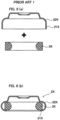
- the resin spring disclosed in WO 97/15207 is formed separately from a main body of a female member. Although the detachment of the resin spring is prevented by an outer rim of the main body, there is a clearance, which allows the resin spring to move and thereby produce noise. Therefore, this resin spring is unsuitable for use in some fields.
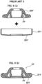
- the resin spring disclosed in JP 2000-279209A is integrated with a main body of a female member. Therefore, the resin spring does not move.
- a resin is coated with a metal, the processing is difficult, resulting in an increase in the molding cost.
- a metal cap 22Y needs to be directly and firmly coupled to a main body 2Y of the female member, and the resin material used is thus limited to a hard resin material. Therefore, the resin spring is likely to lack resilience in joining to a male member. Consequently, the design flexibility of the spring is significantly reduced.
- An object of the present invention is to provide a female member of a snap fastener, the female member having a structure in which a resin spring is separate from a main body of the female member, the resin spring being thus prevented from moving (and accordingly prevented from producing noise), and furthermore, the resin spring being able to be fixed so as not to detach from the main body of the female member.
- a female member of a snap fastener not forming part of the claimed invention is a female member of a snap fastener, the female member including a main body made of a metal and having a cylindrical tube portion and a dish-shaped portion, a resin spring housed in the main body, and a surface covering member crimped onto the cylindrical tube portion, wherein the cylindrical tube portion has a support portion for the resin spring, and the resin spring is fixed in position by the support portion.
- a female member of a snap fastener according to the invention is disclosed in claim 1.
- a resin spring for use in a female member of a snap fastener is a resin plate that can be housed in a main body of the female member, the resin plate having a slot at a central portion thereof.
- the resin spring is shaped like a handguard of a sword and is formed by two wide portions that oppose each other and two narrow portions that oppose each other.
- walls of the wide portions that form the slot of the resin spring are inclined so that the area of the slot gradually increases in a fitting direction.
- the resin spring is fixed in position by the resin spring support portion of the cylindrical tube portion of the female member. Therefore, the resin spring is prevented from moving (and accordingly prevented from producing noise), and furthermore, the resin spring can be fixed so as not to detach from the main body of the female member.
- the resin spring of the present invention is inserted from a back side (the side that is not brought into engagement with a male member), and the metal portion of the outer rim is crimped after the resin spring is fixed in position by the support portion.
- the inscription on the metal portion of the outer rim can be performed in advance before the component is assembled.
- the present invention is similar to JP 2000-279209A .
- the resin spring and the metal portion of the outer rim are not firmly coupled to each other, and therefore the resin can be freely selected. That is to say, a variety of click sensations of the spring including a soft click sensation to a hard click sensation can be selected, a resin with excellent chemical resistance against a specific chemical can be adopted, and there are other various possibilities.
- the resin spring of a "double-spring" type is used, and thus, it is easy to secure an area on which a letter or a figure can be inscribed, and the fashionability can be improved.
- a resin spring not forming part of the claimed invention of a "double-spring” type, which is a resin spring with a shape that can be more easily fixed in position by a support portion, can be obtained.
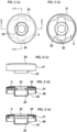
- FIGS. 1 and 2 show a main body 2 and a resin spring 3 that are components constituting a female member 1 of a snap fastener.
- the main body 2 is made of a metal such as brass, and has a dish-shaped portion 22 having a rim portion 21 and a cylindrical tube portion 23 protruding from the center of the dish-shaped portion 22. It is preferable that the entire main body 2 is integrally formed through deep drawing. A letter or a figure (not shown) can be inscribed on a surface of the dish-shaped portion 22.
- the cylindrical tube portion 23 has two slits 24 that are placed near the base thereof and oppose each other, and a leading end of the cylindrical tube portion 23 is bent in an inward direction of the cylindrical tube to form an inward flange 25.
- the resin spring 3 is shaped like a handguard of a Japanese sword, and has a slot 35 that is formed by left and right wide portions 31 and 32 as well as upper and lower narrow portions 33 and 34 and extends in the vertical direction. This shape is similar to a metal spring ("double-spring" type) that has been introduced at the beginning of the specification and that has a shape in which two wire rods oppose each other.
- Polyamide (nylon) or polyester is preferable as the resin of the resin spring 3.
- the resin spring 3 has a length of 11.2 mm in the left-right direction and a length of 11.2 mm in the upper-lower direction
- the slot 35 has a width of 3.6 mm, a length of 9.6 mm in the longitudinal direction, and a thickness of 0.7 mm.
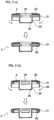
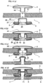
- FIGS. 4(a) to 4(c) illustrates a manner in which the female member 1 of a snap fastener is formed using these components.
- a surface covering member 4 is prepared separately from the female member components 2 and 3 in FIG. 1 .
- the surface covering member 4 has a disk-shaped decorative plate 41 and a cylindrical leg portion 42 extending downward from the center thereof. It is preferable that the decorative plate 41 and the leg portion 42 are integrally formed using a metal such as brass.
- the female member components 2 and 3 in FIG. 1 and the surface covering member 4 are fitted together with a hole 51 that is preliminarily formed in a fabric 5 sandwiched therebetween.
- the leg portion 42 of the surface covering member 4 is crimped onto the flange 25 of the cylindrical tube portion 23 using a crimping machine, and thus the female member 1 of a snap fastener is completed.
- This female member 1 of the snap fastener can be snap-fitted to a male member 7 of the snap fastener that is fixed to a fabric 6.
- the resin spring 3 of the female member 1 of the snap fastener presses against and resiliently supports a head portion 71 of the male member 7.
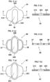
- FIGS. 5 to 7 show modifications of the resin spring.
- a resin spring 3A in FIG. 5 has a slit 36 in one narrow portion 34A. Since the strength is reduced, it is preferable to increase the length in the upper-lower direction of a narrow portion 33A that opposes the narrow portion 34A.
- a resin spring 3B in FIG. 6 not forming part of the claimed invention, has wire springs 37 and 38 instead of the wide portions 31A and 32A.
- Each wire spring extends in a circular arc shape from near a corresponding one end portion of the slot in the longitudinal direction along the rim portion of the dish-shaped portion. With this configuration, a weight reduction can be achieved.
- a resin spring 3C in FIG. 7 is similar to that of Embodiment 1, but has a configuration in which walls of wide portions 31C and 32C that form a slot 35C are inclined so that the area of the slot 35C gradually increases in a fitting direction. With this configuration, the head portion 71 of the male member 7 is easily received in the resin spring 3C, but it is difficult to pull out the head portion 71 therefrom.
Landscapes
- Slide Fasteners, Snap Fasteners, And Hook Fasteners (AREA)
Claims (4)
- Pièce femelle (1) d'un bouton-pression, la pièce femelle (1) d'un bouton-pression comprenant:un corps principal (2) en métal comportant une partie cylindrique du tube (23) et une partie (22) en forme d'assiette;un ressort en résine (3) logé dans le corps principal (2) ; etun élément de recouvrement de surface (4) serti sur le corps principal (2),dans lequel le ressort en résine (3) est une plaque de résine qui peut être logée dans le corps principal (2) de l'élément femelle,la plaque de résine ayant une fente (35, 35A, 35B, 35C) dans sa partie centrale.caractérisée par le fait quela partie cylindrique du tube (23) comporte deux fentes (24) opposées l'une à l'autre, et le ressort en résine (3, 3A, 3B, 3C) est fixé en position par les deux fentes opposées (24).
- Ressort en résine (3, 3A, 3B, 3C) destiné à être utilisé dans un élément femelle (1) d'un bouton-pressionselon la revendication 1,dans lequel le ressort en résine (3, 3A, 3B, 3C) est une plaque en résine qui peut être logée dans un corps principal (2) de l'élément femelle, la plaque de résine ayant une fente (35, 35A, 35B, 35C) dans une partie centrale de celle-ci.
- (Modifié) Le ressort en résine selon la revendication 2,dans lequel le ressort en résine (3, 3A, 3C) est formé de deux parties larges (31, 32 ; 31A, 32A ;31C, 32C) qui s'opposent l'une à l'autre et deux parties étroites (33, 34 ; 33A, 34A ; 33C, 34C) qui s'opposent l'une à l'autre.
- Ressort en résine (3C) selon la revendication 3,
dans lequel les parois des parties larges (31C, 32C) qui forment la fente (35C) du ressort en résine (3C) sont inclinées de sorte que la surface de la fente (35C) augmente progressivement dans le sens de l'ajustement.
Applications Claiming Priority (2)
| Application Number | Priority Date | Filing Date | Title |
|---|---|---|---|
| JP2016124196A JP6542159B2 (ja) | 2016-06-23 | 2016-06-23 | スナップファスナの雌部材及びその中で使用する樹脂製バネ |
| PCT/JP2017/022990 WO2017222008A1 (fr) | 2016-06-23 | 2017-06-22 | Élément femelle de fermeture à pression, et ressort en résine utilisé dans l'élément femelle |
Publications (4)
| Publication Number | Publication Date |
|---|---|
| EP3527100A1 EP3527100A1 (fr) | 2019-08-21 |
| EP3527100A4 EP3527100A4 (fr) | 2020-02-26 |
| EP3527100C0 EP3527100C0 (fr) | 2023-08-09 |
| EP3527100B1 true EP3527100B1 (fr) | 2023-08-09 |
Family
ID=60784156
Family Applications (1)
| Application Number | Title | Priority Date | Filing Date |
|---|---|---|---|
| EP17815474.6A Active EP3527100B1 (fr) | 2016-06-23 | 2017-06-22 | Élément femelle de fermeture à pression, et ressort en résine utilisé dans l'élément femelle |
Country Status (6)
| Country | Link |
|---|---|
| US (1) | US10786050B2 (fr) |
| EP (1) | EP3527100B1 (fr) |
| JP (1) | JP6542159B2 (fr) |
| CN (1) | CN109310184B (fr) |
| ES (1) | ES2962771T3 (fr) |
| WO (1) | WO2017222008A1 (fr) |
Families Citing this family (7)
| Publication number | Priority date | Publication date | Assignee | Title |
|---|---|---|---|---|
| JP2020175045A (ja) * | 2019-04-23 | 2020-10-29 | モリト株式会社 | ロック機能付きホック |
| CN110215017A (zh) * | 2019-07-16 | 2019-09-10 | 赵艳 | 一种弹簧卡式老年扣 |
| WO2021075695A1 (fr) * | 2019-10-14 | 2021-04-22 | 연세대학교 산학협력단 | Soutien-gorge pour radiothérapie |
| USD949000S1 (en) * | 2019-11-29 | 2022-04-19 | Huacai Opto-Electronics Co., Ltd (Yangzhou) | Clip for a lamp |
| US10869518B1 (en) * | 2020-05-05 | 2020-12-22 | Lionhead Helmet Intellectual Properties, Lp | Chin strap assembly for a protective helmet |
| CN114652057B (zh) * | 2022-04-12 | 2023-11-28 | 深圳市联星服装辅料有限公司 | 弹弓钮扣 |
| CN222376918U (zh) * | 2024-06-12 | 2025-01-21 | 浙江实诚塑业有限公司 | 一种用于装饰配件的固定结构 |
Family Cites Families (15)
| Publication number | Priority date | Publication date | Assignee | Title |
|---|---|---|---|---|
| US2829416A (en) * | 1955-11-25 | 1958-04-08 | Sam W Sam | Snap fastener |
| US3999257A (en) * | 1974-10-01 | 1976-12-28 | Hidenosuke Ishizaki | Socket member for snap fastener |
| JPS57184606U (fr) * | 1981-05-19 | 1982-11-24 | ||
| JPS58154613U (ja) * | 1982-04-10 | 1983-10-15 | 倉島 秀雄 | カフスボタン |
| JPS60103306A (ja) * | 1983-11-11 | 1985-06-07 | Agency Of Ind Science & Technol | 光吸収体 |
| JPS60103306U (ja) * | 1983-12-21 | 1985-07-15 | 武田 精 | スナツプフアスナ−の雌スナツプ |
| DE3821003A1 (de) * | 1988-06-22 | 1989-12-28 | Prym Werke William | Matrizenfoermiger federteil eines druckknopfverschlusses |
| AR003848A1 (es) | 1995-10-20 | 1998-09-09 | Cobra Srl | Boton a presion |
| DE19741779B4 (de) | 1997-09-22 | 2004-10-28 | Stocko Fasteners Gmbh | Druckknopf |
| PL2436280T3 (pl) * | 2006-07-12 | 2017-12-29 | Fidlock Gmbh | Mechaniczno-magnetyczna konstrukcja łącząca |
| US8650723B2 (en) * | 2009-08-20 | 2014-02-18 | Rome Fastener Corporation | Non-rotatable snap fasteners |
| WO2011096056A1 (fr) * | 2010-02-03 | 2011-08-11 | Ykk株式会社 | Bouton-pression femelle |
| JP5795855B2 (ja) * | 2010-12-10 | 2015-10-14 | モリト株式会社 | 係止機構付きスナップファスナ |
| JP3192241U (ja) * | 2014-03-20 | 2014-08-07 | 有限会社創芸社 | ホックボタン |
| US20180184766A1 (en) * | 2016-12-30 | 2018-07-05 | Productions Wedoodle Inc. | Swivel clip |
-
2016
- 2016-06-23 JP JP2016124196A patent/JP6542159B2/ja active Active
-
2017
- 2017-06-22 EP EP17815474.6A patent/EP3527100B1/fr active Active
- 2017-06-22 CN CN201780035093.3A patent/CN109310184B/zh active Active
- 2017-06-22 ES ES17815474T patent/ES2962771T3/es active Active
- 2017-06-22 US US16/098,635 patent/US10786050B2/en active Active
- 2017-06-22 WO PCT/JP2017/022990 patent/WO2017222008A1/fr not_active Ceased
Also Published As
| Publication number | Publication date |
|---|---|
| US20190133263A1 (en) | 2019-05-09 |
| EP3527100A1 (fr) | 2019-08-21 |
| EP3527100A4 (fr) | 2020-02-26 |
| US10786050B2 (en) | 2020-09-29 |
| EP3527100C0 (fr) | 2023-08-09 |
| ES2962771T3 (es) | 2024-03-21 |
| CN109310184A (zh) | 2019-02-05 |
| JP2017225652A (ja) | 2017-12-28 |
| JP6542159B2 (ja) | 2019-07-10 |
| WO2017222008A1 (fr) | 2017-12-28 |
| CN109310184B (zh) | 2021-07-09 |
Similar Documents
| Publication | Publication Date | Title |
|---|---|---|
| EP3527100B1 (fr) | Élément femelle de fermeture à pression, et ressort en résine utilisé dans l'élément femelle | |
| EP3228206B1 (fr) | Structure supérieure de bouton-pression femelle, bouton-pression femelle et procédé de fixation de bouton-pression femelle sur un matériau | |
| US9307809B2 (en) | Slide fastener | |
| EP3065972B1 (fr) | Procédé d'assujettissement de housses de garniture de siège sur des coussins de mousse | |
| JP2005315369A (ja) | クリップ | |
| CN103230132B (zh) | 珠宝饰品 | |
| EP3219219A1 (fr) | Décoration de type à assemblage | |
| EP2052637B1 (fr) | Bouton | |
| EP2628404A1 (fr) | Fermeture à glissière, butée supérieure pour fermetures à glissière et procédé de fabrication de fermeture à glissière | |
| US10870380B2 (en) | Integral single-frame two-way headrest with U-shaped single rod | |
| US20150096156A1 (en) | Press-stud | |
| JPH038086Y2 (fr) | ||
| CN108135333A (zh) | 金属扣眼 | |
| KR101915700B1 (ko) | 스냅 파스너 제조방법 | |
| KR101921230B1 (ko) | 스냅용 수단추의 스터드 및 그 제조방법 | |
| JP2006077827A (ja) | クリップ | |
| US20070143969A1 (en) | Cap for button, fixing member and button | |
| JP3189174U (ja) | ジーンズ用の合成樹脂製ボタン | |
| JP6090932B2 (ja) | ジーンズ用の合成樹脂製ボタン | |
| KR101638311B1 (ko) | 3축 코일 안테나의 단자부 및 이의 제조방법 | |
| JP4121980B2 (ja) | スナップファスナー | |
| EP4067676A1 (fr) | Dispositif de fixation pour fixer un élément d'un élément de fixation, élément de fixation et bouton-pression | |
| KR200421524Y1 (ko) | 금속장식판의 보석 설치구조 | |
| CN100536712C (zh) | 可快速拆装的拉链拉引装置 | |
| JPH09224718A (ja) | スナップの雌側の金具とその製造方法 |
Legal Events
| Date | Code | Title | Description |
|---|---|---|---|
| STAA | Information on the status of an ep patent application or granted ep patent |
Free format text: STATUS: THE INTERNATIONAL PUBLICATION HAS BEEN MADE |
|
| PUAI | Public reference made under article 153(3) epc to a published international application that has entered the european phase |
Free format text: ORIGINAL CODE: 0009012 |
|
| STAA | Information on the status of an ep patent application or granted ep patent |
Free format text: STATUS: REQUEST FOR EXAMINATION WAS MADE |
|
| PUAB | Information related to the publication of an a document modified or deleted |
Free format text: ORIGINAL CODE: 0009199EPPU |
|
| PUAI | Public reference made under article 153(3) epc to a published international application that has entered the european phase |
Free format text: ORIGINAL CODE: 0009012 |
|
| 17P | Request for examination filed |
Effective date: 20181220 |
|
| AK | Designated contracting states |
Kind code of ref document: A1 Designated state(s): AL AT BE BG CH CY CZ DE DK EE ES FI FR GB GR HR HU IE IS IT LI LT LU LV MC MK MT NL NO PL PT RO RS SE SI SK SM TR |
|
| AX | Request for extension of the european patent |
Extension state: BA ME |
|
| DAV | Request for validation of the european patent (deleted) | ||
| DAX | Request for extension of the european patent (deleted) | ||
| A4 | Supplementary search report drawn up and despatched |
Effective date: 20200129 |
|
| RIC1 | Information provided on ipc code assigned before grant |
Ipc: A44B 17/00 20060101AFI20200123BHEP |
|
| GRAP | Despatch of communication of intention to grant a patent |
Free format text: ORIGINAL CODE: EPIDOSNIGR1 |
|
| STAA | Information on the status of an ep patent application or granted ep patent |
Free format text: STATUS: GRANT OF PATENT IS INTENDED |
|
| INTG | Intention to grant announced |
Effective date: 20230131 |
|
| GRAS | Grant fee paid |
Free format text: ORIGINAL CODE: EPIDOSNIGR3 |
|
| GRAA | (expected) grant |
Free format text: ORIGINAL CODE: 0009210 |
|
| STAA | Information on the status of an ep patent application or granted ep patent |
Free format text: STATUS: THE PATENT HAS BEEN GRANTED |
|
| AK | Designated contracting states |
Kind code of ref document: B1 Designated state(s): AL AT BE BG CH CY CZ DE DK EE ES FI FR GB GR HR HU IE IS IT LI LT LU LV MC MK MT NL NO PL PT RO RS SE SI SK SM TR |
|
| REG | Reference to a national code |
Ref country code: GB Ref legal event code: FG4D |
|
| REG | Reference to a national code |
Ref country code: CH Ref legal event code: EP |
|
| REG | Reference to a national code |
Ref country code: IE Ref legal event code: FG4D |
|
| REG | Reference to a national code |
Ref country code: DE Ref legal event code: R096 Ref document number: 602017072543 Country of ref document: DE |
|
| U01 | Request for unitary effect filed |
Effective date: 20230906 |
|
| U07 | Unitary effect registered |
Designated state(s): AT BE BG DE DK EE FI FR IT LT LU LV MT NL PT SE SI Effective date: 20230913 |
|
| PG25 | Lapsed in a contracting state [announced via postgrant information from national office to epo] |
Ref country code: GR Free format text: LAPSE BECAUSE OF FAILURE TO SUBMIT A TRANSLATION OF THE DESCRIPTION OR TO PAY THE FEE WITHIN THE PRESCRIBED TIME-LIMIT Effective date: 20231110 |
|
| PG25 | Lapsed in a contracting state [announced via postgrant information from national office to epo] |
Ref country code: IS Free format text: LAPSE BECAUSE OF FAILURE TO SUBMIT A TRANSLATION OF THE DESCRIPTION OR TO PAY THE FEE WITHIN THE PRESCRIBED TIME-LIMIT Effective date: 20231209 |
|
| PG25 | Lapsed in a contracting state [announced via postgrant information from national office to epo] |
Ref country code: RS Free format text: LAPSE BECAUSE OF FAILURE TO SUBMIT A TRANSLATION OF THE DESCRIPTION OR TO PAY THE FEE WITHIN THE PRESCRIBED TIME-LIMIT Effective date: 20230809 Ref country code: NO Free format text: LAPSE BECAUSE OF FAILURE TO SUBMIT A TRANSLATION OF THE DESCRIPTION OR TO PAY THE FEE WITHIN THE PRESCRIBED TIME-LIMIT Effective date: 20231109 Ref country code: IS Free format text: LAPSE BECAUSE OF FAILURE TO SUBMIT A TRANSLATION OF THE DESCRIPTION OR TO PAY THE FEE WITHIN THE PRESCRIBED TIME-LIMIT Effective date: 20231209 Ref country code: HR Free format text: LAPSE BECAUSE OF FAILURE TO SUBMIT A TRANSLATION OF THE DESCRIPTION OR TO PAY THE FEE WITHIN THE PRESCRIBED TIME-LIMIT Effective date: 20230809 Ref country code: GR Free format text: LAPSE BECAUSE OF FAILURE TO SUBMIT A TRANSLATION OF THE DESCRIPTION OR TO PAY THE FEE WITHIN THE PRESCRIBED TIME-LIMIT Effective date: 20231110 |
|
| PG25 | Lapsed in a contracting state [announced via postgrant information from national office to epo] |
Ref country code: PL Free format text: LAPSE BECAUSE OF FAILURE TO SUBMIT A TRANSLATION OF THE DESCRIPTION OR TO PAY THE FEE WITHIN THE PRESCRIBED TIME-LIMIT Effective date: 20230809 |
|
| REG | Reference to a national code |
Ref country code: ES Ref legal event code: FG2A Ref document number: 2962771 Country of ref document: ES Kind code of ref document: T3 Effective date: 20240321 |
|
| PG25 | Lapsed in a contracting state [announced via postgrant information from national office to epo] |
Ref country code: SM Free format text: LAPSE BECAUSE OF FAILURE TO SUBMIT A TRANSLATION OF THE DESCRIPTION OR TO PAY THE FEE WITHIN THE PRESCRIBED TIME-LIMIT Effective date: 20230809 Ref country code: RO Free format text: LAPSE BECAUSE OF FAILURE TO SUBMIT A TRANSLATION OF THE DESCRIPTION OR TO PAY THE FEE WITHIN THE PRESCRIBED TIME-LIMIT Effective date: 20230809 Ref country code: CZ Free format text: LAPSE BECAUSE OF FAILURE TO SUBMIT A TRANSLATION OF THE DESCRIPTION OR TO PAY THE FEE WITHIN THE PRESCRIBED TIME-LIMIT Effective date: 20230809 Ref country code: SK Free format text: LAPSE BECAUSE OF FAILURE TO SUBMIT A TRANSLATION OF THE DESCRIPTION OR TO PAY THE FEE WITHIN THE PRESCRIBED TIME-LIMIT Effective date: 20230809 |
|
| REG | Reference to a national code |
Ref country code: DE Ref legal event code: R097 Ref document number: 602017072543 Country of ref document: DE |
|
| PLBE | No opposition filed within time limit |
Free format text: ORIGINAL CODE: 0009261 |
|
| STAA | Information on the status of an ep patent application or granted ep patent |
Free format text: STATUS: NO OPPOSITION FILED WITHIN TIME LIMIT |
|
| U20 | Renewal fee for the european patent with unitary effect paid |
Year of fee payment: 8 Effective date: 20240605 |
|
| 26N | No opposition filed |
Effective date: 20240513 |
|
| PG25 | Lapsed in a contracting state [announced via postgrant information from national office to epo] |
Ref country code: MC Free format text: LAPSE BECAUSE OF FAILURE TO SUBMIT A TRANSLATION OF THE DESCRIPTION OR TO PAY THE FEE WITHIN THE PRESCRIBED TIME-LIMIT Effective date: 20230809 |
|
| REG | Reference to a national code |
Ref country code: CH Ref legal event code: PL |
|
| PG25 | Lapsed in a contracting state [announced via postgrant information from national office to epo] |
Ref country code: IE Free format text: LAPSE BECAUSE OF NON-PAYMENT OF DUE FEES Effective date: 20240622 |
|
| PG25 | Lapsed in a contracting state [announced via postgrant information from national office to epo] |
Ref country code: CH Free format text: LAPSE BECAUSE OF NON-PAYMENT OF DUE FEES Effective date: 20240630 |
|
| PGFP | Annual fee paid to national office [announced via postgrant information from national office to epo] |
Ref country code: GB Payment date: 20250618 Year of fee payment: 9 |
|
| U20 | Renewal fee for the european patent with unitary effect paid |
Year of fee payment: 9 Effective date: 20250627 |
|
| PGFP | Annual fee paid to national office [announced via postgrant information from national office to epo] |
Ref country code: ES Payment date: 20250728 Year of fee payment: 9 |
|
| PG25 | Lapsed in a contracting state [announced via postgrant information from national office to epo] |
Ref country code: CY Free format text: LAPSE BECAUSE OF FAILURE TO SUBMIT A TRANSLATION OF THE DESCRIPTION OR TO PAY THE FEE WITHIN THE PRESCRIBED TIME-LIMIT; INVALID AB INITIO Effective date: 20170622 |
|
| PG25 | Lapsed in a contracting state [announced via postgrant information from national office to epo] |
Ref country code: HU Free format text: LAPSE BECAUSE OF FAILURE TO SUBMIT A TRANSLATION OF THE DESCRIPTION OR TO PAY THE FEE WITHIN THE PRESCRIBED TIME-LIMIT; INVALID AB INITIO Effective date: 20170622 |