EP3527159A2 - Reconstruction 3d et guidage basé sur un suivi combiné d'ultrasons endobronchique et magnétique - Google Patents
Reconstruction 3d et guidage basé sur un suivi combiné d'ultrasons endobronchique et magnétique Download PDFInfo
- Publication number
- EP3527159A2 EP3527159A2 EP19157516.6A EP19157516A EP3527159A2 EP 3527159 A2 EP3527159 A2 EP 3527159A2 EP 19157516 A EP19157516 A EP 19157516A EP 3527159 A2 EP3527159 A2 EP 3527159A2
- Authority
- EP
- European Patent Office
- Prior art keywords
- image data
- computing device
- target
- model
- surgical site
- Prior art date
- Legal status (The legal status is an assumption and is not a legal conclusion. Google has not performed a legal analysis and makes no representation as to the accuracy of the status listed.)
- Withdrawn
Links
Images


Classifications
-
- A—HUMAN NECESSITIES
- A61—MEDICAL OR VETERINARY SCIENCE; HYGIENE
- A61B—DIAGNOSIS; SURGERY; IDENTIFICATION
- A61B5/00—Measuring for diagnostic purposes; Identification of persons
- A61B5/06—Devices, other than using radiation, for detecting or locating foreign bodies ; Determining position of diagnostic devices within or on the body of the patient
- A61B5/065—Determining position of the probe employing exclusively positioning means located on or in the probe, e.g. using position sensors arranged on the probe
- A61B5/066—Superposing sensor position on an image of the patient, e.g. obtained by ultrasound or x-ray imaging
-
- A—HUMAN NECESSITIES
- A61—MEDICAL OR VETERINARY SCIENCE; HYGIENE
- A61B—DIAGNOSIS; SURGERY; IDENTIFICATION
- A61B34/00—Computer-aided surgery; Manipulators or robots specially adapted for use in surgery
- A61B34/20—Surgical navigation systems; Devices for tracking or guiding surgical instruments, e.g. for frameless stereotaxis
-
- A—HUMAN NECESSITIES
- A61—MEDICAL OR VETERINARY SCIENCE; HYGIENE
- A61B—DIAGNOSIS; SURGERY; IDENTIFICATION
- A61B5/00—Measuring for diagnostic purposes; Identification of persons
- A61B5/06—Devices, other than using radiation, for detecting or locating foreign bodies ; Determining position of diagnostic devices within or on the body of the patient
- A61B5/061—Determining position of a probe within the body employing means separate from the probe, e.g. sensing internal probe position employing impedance electrodes on the surface of the body
- A61B5/062—Determining position of a probe within the body employing means separate from the probe, e.g. sensing internal probe position employing impedance electrodes on the surface of the body using magnetic field
-
- A—HUMAN NECESSITIES
- A61—MEDICAL OR VETERINARY SCIENCE; HYGIENE
- A61B—DIAGNOSIS; SURGERY; IDENTIFICATION
- A61B8/00—Diagnosis using ultrasonic, sonic or infrasonic waves
- A61B8/08—Clinical applications
- A61B8/0833—Clinical applications involving detecting or locating foreign bodies or organic structures
- A61B8/085—Clinical applications involving detecting or locating foreign bodies or organic structures for locating body or organic structures, e.g. tumours, calculi, blood vessels, nodules
-
- A—HUMAN NECESSITIES
- A61—MEDICAL OR VETERINARY SCIENCE; HYGIENE
- A61B—DIAGNOSIS; SURGERY; IDENTIFICATION
- A61B8/00—Diagnosis using ultrasonic, sonic or infrasonic waves
- A61B8/12—Diagnosis using ultrasonic, sonic or infrasonic waves in body cavities or body tracts, e.g. by using catheters
-
- A—HUMAN NECESSITIES
- A61—MEDICAL OR VETERINARY SCIENCE; HYGIENE
- A61B—DIAGNOSIS; SURGERY; IDENTIFICATION
- A61B8/00—Diagnosis using ultrasonic, sonic or infrasonic waves
- A61B8/52—Devices using data or image processing specially adapted for diagnosis using ultrasonic, sonic or infrasonic waves
- A61B8/5269—Devices using data or image processing specially adapted for diagnosis using ultrasonic, sonic or infrasonic waves involving detection or reduction of artifacts
-
- A—HUMAN NECESSITIES
- A61—MEDICAL OR VETERINARY SCIENCE; HYGIENE
- A61B—DIAGNOSIS; SURGERY; IDENTIFICATION
- A61B90/00—Instruments, implements or accessories specially adapted for surgery or diagnosis and not covered by any of the groups A61B1/00 - A61B50/00, e.g. for luxation treatment or for protecting wound edges
- A61B90/36—Image-producing devices or illumination devices not otherwise provided for
- A61B90/37—Surgical systems with images on a monitor during operation
-
- A—HUMAN NECESSITIES
- A61—MEDICAL OR VETERINARY SCIENCE; HYGIENE
- A61B—DIAGNOSIS; SURGERY; IDENTIFICATION
- A61B34/00—Computer-aided surgery; Manipulators or robots specially adapted for use in surgery
- A61B34/10—Computer-aided planning, simulation or modelling of surgical operations
- A61B2034/101—Computer-aided simulation of surgical operations
- A61B2034/105—Modelling of the patient, e.g. for ligaments or bones
-
- A—HUMAN NECESSITIES
- A61—MEDICAL OR VETERINARY SCIENCE; HYGIENE
- A61B—DIAGNOSIS; SURGERY; IDENTIFICATION
- A61B34/00—Computer-aided surgery; Manipulators or robots specially adapted for use in surgery
- A61B34/20—Surgical navigation systems; Devices for tracking or guiding surgical instruments, e.g. for frameless stereotaxis
- A61B2034/2046—Tracking techniques
- A61B2034/2051—Electromagnetic tracking systems
-
- A—HUMAN NECESSITIES
- A61—MEDICAL OR VETERINARY SCIENCE; HYGIENE
- A61B—DIAGNOSIS; SURGERY; IDENTIFICATION
- A61B34/00—Computer-aided surgery; Manipulators or robots specially adapted for use in surgery
- A61B34/20—Surgical navigation systems; Devices for tracking or guiding surgical instruments, e.g. for frameless stereotaxis
- A61B2034/2046—Tracking techniques
- A61B2034/2055—Optical tracking systems
-
- A—HUMAN NECESSITIES
- A61—MEDICAL OR VETERINARY SCIENCE; HYGIENE
- A61B—DIAGNOSIS; SURGERY; IDENTIFICATION
- A61B34/00—Computer-aided surgery; Manipulators or robots specially adapted for use in surgery
- A61B34/20—Surgical navigation systems; Devices for tracking or guiding surgical instruments, e.g. for frameless stereotaxis
- A61B2034/2046—Tracking techniques
- A61B2034/2063—Acoustic tracking systems, e.g. using ultrasound
-
- A—HUMAN NECESSITIES
- A61—MEDICAL OR VETERINARY SCIENCE; HYGIENE
- A61B—DIAGNOSIS; SURGERY; IDENTIFICATION
- A61B90/00—Instruments, implements or accessories specially adapted for surgery or diagnosis and not covered by any of the groups A61B1/00 - A61B50/00, e.g. for luxation treatment or for protecting wound edges
- A61B90/36—Image-producing devices or illumination devices not otherwise provided for
- A61B90/37—Surgical systems with images on a monitor during operation
- A61B2090/378—Surgical systems with images on a monitor during operation using ultrasound
-
- A—HUMAN NECESSITIES
- A61—MEDICAL OR VETERINARY SCIENCE; HYGIENE
- A61B—DIAGNOSIS; SURGERY; IDENTIFICATION
- A61B90/00—Instruments, implements or accessories specially adapted for surgery or diagnosis and not covered by any of the groups A61B1/00 - A61B50/00, e.g. for luxation treatment or for protecting wound edges
- A61B90/39—Markers, e.g. radio-opaque or breast lesions markers
- A61B2090/3983—Reference marker arrangements for use with image guided surgery
Definitions
- the present disclosure relates to the generation of visual guidance for surgical procedures and, more particularly, to systems and methods for capturing ultrasound images of structures within a patient's chest and generating three-dimensional renderings of the ultrasound images to provide visual guidance during the surgical procedures..
- Endobronchial navigation is one type of such minimally-invasive surgical procedure, and involves insertion of one or more surgical instruments via a bronchoscope and/or other catheter guide assembly into a patient's airways, and navigating the catheter through the airway tree and/or parenchyma to a diagnosis or treatment site.
- Various systems and surgical instruments have been developed to aid clinicians during such endobronchial navigation procedures, such as to assist with placing a catheter or other surgical instrument at a desired diagnosis or treatment site.
- existing systems rely on optical images provided by cameras in the bronchoscope or catheter and/or computed tomography (CT) images acquired pre-procedure.
- CT computed tomography
- Optical images alone are often insufficient for accurately guiding surgical instruments to a desired diagnosis or treatment site because optical cameras cannot capture images of structures behind airway walls or behind obstructions in the airways. Additionally, due to the complex structure of a patient's bronchial (airway) tree, it is often difficult to identify exactly where in the airway tree the bronchoscope or catheter is located. As such, the systems and methods described hereinbelow provide improvements in imaging and visualization techniques for use while navigating within a patient's airways during surgical procedures.
- an illustrative surgical system includes an electromagnetic (EM) tracking system including a EM field generator configured to generate an EM field about a surgical site, a surgical tool including an ultrasound sensor and an EM sensor, a display device, and a computing device including a processor and a memory storing instructions which, when executed by the processor, cause the computing device to receive first image data of the surgical site, identify a structure in the first image data, identify a target in the first image data, generate a three-dimensional (3D) model of the surgical site based on the first image data and the identified structure and target, determine a pathway to the target, cause the display device to display the pathway to the target, determine a position of the surgical tool within the surgical site based on tracking data received from the EM tracking system, the tracking data indicating a position of the EM sensor within the EM field, register the 3D model to the surgical site, receive second image data from the ultrasound sensor, generate a 3D
- EM electromagnetic
- the surgical tool further includes an expandable balloon.
- the instructions when executed by the processor, further cause the computing device to cause the display device to display guidance for positioning the surgical tool relative to the target.
- the instructions when executed by the processor, further cause the computing device to cause the display device to display guidance for moving the surgical tool relative to the target while the ultrasound sensor captures the second image data.
- the instructions when executed by the processor, further cause the computing device to cause the display device to display a view of the 3D model showing regions of the surgical site for which second image data has been received with a first characteristic, and regions of the surgical site for which second image data has not been received with a second characteristic.
- the instructions when executed by the processor, further cause the computing device to cause the display device to display a view of the first image data showing regions of the surgical site for which second image data has been received with a first characteristic, and regions of the surgical site for which second image data has not been received with a second characteristic.
- the instructions when executed by the processor, further cause the computing device to process the second image data to remove artifacts from the second image data
- the 3D volume rendering is generated based on at least a portion of the second image data and the determined position of the surgical tool.
- the instructions when executed by the processor, further cause the computing device to register the 3D volume rendering to the 3D model.
- the instructions when executed by the processor, further cause the computing device to register the 3D volume rendering to the first image data.
- the instructions when executed by the processor, further cause the computing device to update the 3D volume rendering based on the identified structure.
- the structure includes one or more of a bronchial tree, a vascular tree, a lymphatic tree, a lesion, a cyst, an esophagus, a pleural surface, a lymph node, an organ, and a marker.
- the instructions when executed by the processor, further cause the computing device to cause the display device to display the updated 3D volume rendering.
- the instructions when executed by the processor, further cause the computing device to cause the display device to display an individual slice image of the 3D volume rendering.
- the instructions when executed by the processor, further cause the computing device to update the registration of the 3D model to the surgical site based on the registration of the 3D volume rendering to the 3D model.
- the instructions when executed by the processor, further cause the computing device to update the 3D model based on the second image data.
- an illustrative surgical system includes an EM tracking system including a EM field generator configured to generate an EM field about a surgical site, a surgical tool including an ultrasound sensor and an EM sensor, and a computing device including a processor and a memory storing instructions which, when executed by the processor, cause the computing device to receive first image data of the surgical site, generate a 3D model of the surgical site based on an identified target in the image data, determine a pathway to the target, determine a position of the surgical tool within the surgical site based on a determined position of the EM sensor within the EM field, receive second image data from the ultrasound sensor, and generate a 3D volume rendering of the target based on the second image data.
- the instructions when executed by the processor, further cause the computing device to register the 3D volume rendering of the target to the 3D model of the surgical site.
- an illustrative method for generating visual guidance for a surgical procedure includes receiving first image data of a surgical site, generating a three-dimensional (3D) model of the surgical site, determining a pathway to a target identified in the first image data, displaying the pathway to the target on a display, determining a position of an electromagnetic (EM) sensor within an EM field generated about the surgical site, receiving second image data of the target from an ultrasound sensor, and generating a 3D volume rendering of the target based on the second image data.
- EM electromagnetic
- the method includes registering the 3D volume rendering of the target to the 3D model of the surgical site.
- the present disclosure relates to systems and methods for providing visual guidance during surgical procedures. More particularly, the disclosure relates to capturing ultrasound image data of structures inside a patient's chest, creating three-dimensional (3D) renderings of the structures based on the ultrasound image data, registering the 3D renderings to a 3D model of the patient's chest generated based on pre-procedure radiographic image data of the patient's chest, and displaying the 3D renderings in conjunction with and/or in addition to the 3D model during navigation of surgical tools about the patient's chest.
- 3D three-dimensional
- Pre-procedural imaging of the patient's chest may be performed to create a visual representation, such as a three-dimensional (3D) model of a patient's chest, including lumens such as the bronchial, vascular, and lymphatic trees, pleural surfaces and fissures of the patient's lungs, and/or tumors or other aberrant structures that may be present in the patient's lungs.
- the 3D model may be generated using one or more software applications executing on a computer.
- the application may, for example, generate the 3D model or map of the patient's chest based on radiographically obtained images, such as computed tomography (CT) images, magnetic resonance imaging (MRI) images, positron emission tomography (PET) images, X-ray images, cone-beam computed tomography (CBCT) images, and/or any other applicable imaging modality.
- CT computed tomography
- MRI magnetic resonance imaging
- PET positron emission tomography
- CBCT cone-beam computed tomography
- the images may be processed to create a volume of image data of the patient's chest based upon which the 3D model is generated.
- the image data and/or 3D model may further be processed to identify one or more targets, such as tumors, lesions, or other aberrant structures, in the patient's chest.
- the application may identify the locations of lumens, such as airways, blood vessels, and/or lymphatic structures from the radiographic image data, and further determine the locations of one or more diagnostic or treatment targets
- the application may then receive or load a model lymph node map, such as the International Association for the Study of Lung Cancer (IASLC) map, which includes the locations of lymph nodes in a model patient's body. Thereafter, the application may fit the model lymph node map to the 3D model to align the model map with the real patient's body and the identified structures in the patient's chest to identify and label lymph nodes and/or other structures on the 3D model.
- a model lymph node map such as the International Association for the Study of Lung Cancer (IASLC) map
- IASLC International Association for the Study of Lung Cancer
- one or more lymphatic tree maps of the patient's lymphatic system may be generated based on the model lymph node map fitted to the 3D model.
- the generated lymphatic tree maps may further be fitted and/or updated based on known locations of lymph nodes in the patient's chest.
- the 3D model, radiographic image data, and/or lymphatic tree map may then be displayed to and viewed by a clinician and/or surgeon to plan a medical procedure, such as a diagnostic or treatment procedure, including biopsy, ablation, radiation, and/or surgical or interventional procedure.
- a clinician may review the 3D model, radiographic image data, and/or lymphatic tree map to identify one or more structures, such as lymph nodes, lesions, and/or other targets for diagnosis and/or sampling (such as biopsy).
- the application may then determine a path to the identified structures to assist a clinician with navigating one or more surgical tools through the patient's airways to the structures, as further described below.
- the 3D model is registered to the patient's body, as further described below.
- One or more surgical tools are then tracked via an electromagnetic tracking system as the tools are navigated via the patient's airways to one of the structures.
- ultrasound image data of the structure may be captured via an ultrasound sensor coupled to or included in the surgical tool.
- a 3D rendering of the structure may then be generated based on the ultrasound image data.
- the 3D rendering is then registered to the 3D model, radiographic image data, and/or lymphatic tree map based on the known position of the surgical tool relative to the 3D model when the ultrasound image data were obtained.
- the 3D rendering and/or the 3D model, as well as the registration of the 3D model to the patient's body, may then be updated and/or augmented.
- the 3D rendering, the 3D model, and/or a fusion of the two may then be displayed during a subsequent diagnostic or treatment procedure.
- the systems and methods described herein are useful in various planning and/or navigation contexts for diagnostic and/or treatment procedures performed in the patient's chest.
- the systems and methods may provide the clinician with various views of the patient's lungs and the bronchial, vascular, and lymphatic trees therein.
- the systems and methods may provide the clinician with the ability to view and/or determine various characteristics of the targets, as well as view the position of surgical tools relative to the targets with greater detail than is possible with conventional systems.
- an electromagnetic navigation (EMN) system 100 suitable for implementing methods for performing endobronchial diagnostic and/or treatment procedures in an area of a patient's chest is provided in accordance with the present disclosure.
- One such EMN system 100 is the ELECTROMAGNETIC NAVIGATION BRONCHOSCOPY (ENB) system currently sold by Covidien LP, a division of Medtronic PLC.
- the EMN system 100 is used to perform one or more treatment procedures on a patient supported on an operating table 40.
- the EMN system 100 generally includes a bronchoscope 50, monitoring equipment 30, an electromagnetic (EM) tracking system 70, and a computing device 80.
- the bronchoscope 50 is configured for insertion through the patient's mouth and/or nose into the patient's airways.
- the bronchoscope 50 includes a source of illumination and a video imaging system (not explicitly shown) including at least one optical sensor (such as a camera) which is in operative communication with the monitoring equipment 30, for example, a video display, for displaying the video images received from the video imaging system of the bronchoscope 50.
- the bronchoscope 50 further includes an ultrasound sensor (not shown in FIG. 1 ).
- the bronchoscope 50 may operate in conjunction with a catheter guide assembly 90.
- the catheter guide assembly 90 includes an extended working channel (EWC) 96 configured for insertion through a working channel of the bronchoscope 50 into the patient's airways (although the catheter guide assembly 90 may alternatively be used without the bronchoscope 50).
- the catheter guide assembly 90 further includes a handle 91 connected to the EWC 96, and which can be manipulated by rotation and compression to steer the EWC 96.
- a locatable guide (LG) 92 including an EM sensor 94, is inserted into the EWC 96 and locked into position such that the EM sensor 94 extends a desired distance beyond a distal tip 93 of the EWC 96.
- the location of the EM sensor 94, and thus the distal tip 93 of the EWC 96, within an EM field generated by the EM field generator 76, can be derived by a tracking module 72 and the computing device 80.
- a tracking module 72 and the computing device 80 For a more detailed description of the catheter guide assembly 90, reference is made to commonly-owned U.S. Patent No. 9,247,992 , entitled “MICROWAVE ABLATION CATHETER AND METHOD OF UTILIZING THE SAME", filed on March 15, 2013, by Ladtkow et al., the entire contents of which are hereby incorporated by reference.
- a six degrees-of-freedom EM tracking system 70 e.g., similar to those disclosed in U.S. Patent No. 6,188,355 , entitled “WIRELESS SIX-DEGREE-OF-FREEDOM LOCATOR", filed on December 12, 1997, by Pinhas Gilboa, U.S. Patent No. 6,833,814 , entitled “INTRABODY NAVIGATION SYSTEM FOR MEDICAL APPLICATIONS", filed on August 2, 1998, by Gilboa et al., and PCT Publication No.
- the EM tracking system 70 may be configured for use with the catheter guide assembly 90 to track a position of the EM sensor 94 as it moves in conjunction with the EWC 96 through the airways of the patient, as detailed below.
- the EM tracking system 70 includes the tracking module 72, a plurality of reference sensors 74, and an EM field generator 76. As shown in FIG. 1 , the EM field generator 76 is positioned beneath the patient. The EM field generator 76 and the plurality of reference sensors 74 are interconnected with the tracking module 72, which derives the location of each reference sensor 74 in the six degrees of freedom. One or more of the reference sensors 74 are placed on or attached to the chest of the patient. The six degrees of freedom coordinates of the reference sensors 74 are sent as data to the computing device 80, which includes an application 81, where the data from the reference sensors 74 are used to calculate a patient coordinate frame of reference.
- the EM sensor 94 is described above as being included in the LG 92, it is also envisioned that the EM sensor 94 may be embedded or incorporated within a treatment tool, such as a endobronchial ultrasound (EBUS) 62 tool and/or an ablation tool 64, or a diagnostic tool, such as a camera tool, a light sensor, a linear ultrasound tool, etc., where the treatment tool may alternatively be utilized for navigation without need of the LG 92 or the necessary tool exchanges that use of the LG 92 requires.
- the EM sensor 94 may also be embedded or incorporated within the EWC 96, such as at a distal portion of the EWC 96, thereby enabling tracking of the distal portion of the EWC 96 without the need for a separate LG 92.
- treatment tools 62, 64 are configured to be insertable into the catheter guide assembly 90 following navigation to a target and removal of the LG 92.
- the EBUS 62 includes at least one ultrasound sensor 63 configured to capture ultrasound images.
- the ultrasound sensor may be configured to capture ultrasound image data using various frequencies and/or modes of operation, as will be known to those skilled in the art.
- One example mode of operation includes Doppler.
- the EBUS 62 may further include a biopsy tool, such as a needle and/or a brush, which may be used to collect one or more tissue samples from the target.
- the EBUS 62 may further include one or more expandable balloons which may be used to lock the position of the EBUS 62 during ultrasound imaging and/or while a biopsy procedure is being performed.
- the EBUS 62 is further configured for use in conjunction with the tracking system 70 to facilitate navigation of the EBUS 62 to the target by tracking the position of EM sensor 94, and thus the EBUS 62, as it is navigated through the patient's airways and manipulated relative to the target.
- the EBUS 62 may additionally be coupled to an ultrasound workstation (not shown in FIG. 1 ) and/or the computing device 80 to facilitate capture, processing, and analysis of ultrasound images acquired by the ultrasound sensor 63.
- the ablation tool 64 is configured to be operated with a generator 66, such as a radio frequency generator or a microwave generator, and may include any of a variety of ablation tools and/or catheters, examples of which are more fully described in commonly-owned U.S. Patent No.
- the computing device 80 includes hardware and/or software, such as an application 81, used to facilitate the various phases of an EMN procedure, as described further below.
- computing device 80 utilizes radiographic image data acquired from a CT scan, cone beam computed tomography (CBCT) scan, magnetic resonance imaging (MRI) scan, positron emission tomography (PET) scan, X-ray scan, and/or any other suitable imaging modality to generate and display a 3D model of the patient's airways, identify a target on the radiographic image data and/or 3D model (automatically, semi-automatically or manually), and allow for the determination and selection of a pathway through the patient's airways to the target.
- CBCT cone beam computed tomography
- MRI magnetic resonance imaging
- PET positron emission tomography
- X-ray scan X-ray scan
- the 3D model may be presented on a display device associated with the computing device 80, or in any other suitable fashion.
- An example of the planning software described herein can be found in commonly-assigned U.S. Patent No. 9,459,770, filed by Baker et al. on March 15, 2013 , and entitled “PATHWAY PLANNING SYSTEM AND METHOD", the entire contents of which are incorporated herein by reference. Further examples of the planning software can be found in commonly-assigned U.S. Patent No. 9,770,216 , entitled “SYSTEM AND METHOD FOR NAVIGATING WITHIN THE LUNG”, filed on June 29, 2015, by Brown et al., the entire contents of which are incorporated herein by reference.
- various views of the 3D model may be displayed to and manipulated by a clinician to facilitate identification of a target.
- the target may be one or more lesions or lymph nodes, a surgical site where treatment is to be performed, and/or a portion of, entire lobe, or multiple lobes of the patient's lungs requiring treatment.
- the 3D model may include, among other things, a model airway tree 402 corresponding to the actual airways of the patient's lungs, and show the various passages, branches, and bifurcations of the patient's actual airway tree.
- the 3D model may include lesions 420, markers, blood vessels and vascular structures 404, lymph nodes and other lymphatic structures 410, organs, other physiological structures, and/or a 3D rendering of the pleural surfaces 406 and fissures 408 of the patient's lungs.
- Some or all of the aforementioned elements may be selectively displayed, such that the clinician may choose which elements should be displayed when viewing the 3D model.
- one or more 3D renderings may be generated based on the ultrasound image data acquired by the ultrasound sensor 63 of the EBUS 62, and these 3D renderings may additionally be displayed in conjunction with or separate from the 3D model.
- EM sensor 94 in conjunction with tracking system 70, enables tracking of EM sensor 94 (and thus distal tip 93 of EWC 96 or tools 62, 64) as EM sensor 94 is advanced through the patient's airways following the pathway planned during the planning phase of the EMN procedure.
- the 3D model is registered with the patient's actual airways.
- One potential method of registration involves navigating LG 92 (or another tool including the EM sensor 94) into each lobe of the patient's lungs to at least the second bifurcation of the airways of that lobe.
- the position of LG 92 is tracked during this registration phase, and the 3D model is iteratively updated based on the tracked position of the locatable guide within the actual airways of the patient's lungs.
- This registration process is described in commonly-assigned U.S. Patent Appl. Publ. No. 2011/0085720 , entitled “AUTOMATIC REGISTRATION TECHNIQUE,” filed on May 14, 2010, by Barak et al., and U.S. Patent Appl. Publ. No. 2016/0000356 , entitled “REAL-TIME AUTOMATIC REGISTRATION FEEDBACK", filed on July 2, 2015, by Brown et al., the entire contents of each of which are incorporated herein by reference. While the registration process focuses on aligning the patient's actual airways with the airways of the 3D model, registration also ensures that the position of vascular structures, lymphatic structures, pleural surfaces, and fissures of the lungs are accurately determined.
- the EBUS 62 may acquire ultrasound image data of various portions of the patient's chest, such as lesions, lymph nodes, and/or other structures.
- the computing device 80 may then generate the aforementioned 3D renderings of lesions, lymph nodes, and/or other structures based on the ultrasound image data.
- the computing device 80 may then register the 3D renderings to the 3D model based on the known position of the EBUS 62 while the ultrasound image data are obtained (based on the EM sensor 94 coupled to the EBUS 62).
- the computing device 80 may then update and/or enhance the 3D model based on the ultrasound image data and/or the 3D renderings.
- the computing device 80 may further update and/or enhance the registration of the 3D model to the patient's body based on the registration of the 3D renderings to the 3D model.
- the ultrasound image data may provide additional clarity and/or identify structures that are not visible in the radiographic image data and/or the 3D model, and the positions of such additional structures may be used to improve the registration of the 3D model to the patient's body.
- the computing device 80 may then generate a plan for obtaining biopsy samples from one or more of the lesions or lymph nodes of which 3D renderings were generated.
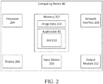
- Computing device 80 may include a memory 202, a processor 204, a display 206, a network interface 208, an input device 210, and/or an output module 212.
- Memory 202 may store the application 81 and/or image data 214.
- the application 81 may, when executed by the processor 204, cause the display 206 to present a graphical user interface (GUI) based on GUI instructions 216.
- GUI graphical user interface
- the application 81 may also provide the interface between the tracked position of EM sensor 94 and the image and planning data developed in the pathway planning phase.
- the memory 202 may include any non-transitory computer-readable storage media for storing data and/or software that is executable by the processor 204 and which controls the operation of the computing device 80.
- the memory 202 may include one or more solid-state storage devices such as flash memory chips.
- the memory 202 may include one or more mass storage devices connected to the processor 204 through a mass storage controller (not shown) and a communications bus (not shown).
- mass storage controller not shown
- communications bus not shown
- computer readable storage media includes non-transitory, volatile and non-volatile, removable and non-removable media implemented in any method or technology for storage of information such as computer-readable instructions, data structures, program modules or other data.
- computer-readable storage media includes RAM, ROM, EPROM, EEPROM, flash memory or other solid state memory technology, CD-ROM, DVD, Blu-Ray or other optical storage, magnetic cassettes, magnetic tape, magnetic disk storage or other magnetic storage devices, or any other medium which can be used to store the desired information and which can be accessed by the computing device 80.
- the network interface 208 may be configured to connect to a network such as a local area network (LAN) consisting of a wired network and/or a wireless network, a wide area network (WAN), a wireless mobile network, a Bluetooth network, and/or the internet.
- the input device 210 may be any device by means of which a user may interact with the computing device 80, such as, for example, a mouse, keyboard, foot pedal, touch screen, and/or voice interface.
- the output module 212 may include any connectivity port or bus, such as, for example, parallel ports, serial ports, universal serial busses (USB), or any other similar connectivity port known to those skilled in the art.
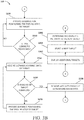
- FIGS. 3A , 3B , 3C , and 3D referred to collectively as FIG. 3 ) there is shown a flowchart of an illustrative method 300 of performing diagnosis and/or treatment of an area of a patient's lungs, in accordance with an embodiment of the present disclosure.
- the method 300 includes various steps described in an ordered sequence. However, those skilled in the art will appreciate that one or more steps of the method 300 may be performed in a different order, repeated, and/or omitted without departing from the scope of the present disclosure.
- the below description of the method 300 refers to various actions or tasks performed by the computing device 80, but those skilled in the art will appreciate that in some instances, the computing device 80 performs the actions or tasks via one or more software applications, such as the application 81, executing on the computing device 80.
- the method 300 may begin with a planning phase 301 including various steps that may be performed prior to a patient being placed on the table 40 for the diagnostic and/or treatment procedure.
- the patient may undergo radiographic imaging and the radiographic image data processed by the computing device 80 prior to the patient coming in for the diagnostic and/or treatment procedure.
- the steps of the planning phase 301 may be performed as part of a system configuration while the patient is already on the table 40, and thus the patient may remain in the same position after the radiographic imaging is performed.
- the computing device 80 receives first image data a surgical site.
- the surgical site includes at least a portion of the patient's body.
- the first image data may include image data from multiple pre-operative scans. In other embodiments, only image data from a most recent scan may be used.
- the first image data may be received in, or converted to, a uniform data format, such as the digital imaging and communications in medicine (DICOM) standard.
- DICOM digital imaging and communications in medicine
- the first image data may include image data from a CT scan, a CBCT scan, a MRI scan, a PET scan, an X-ray scan, etc.
- the computing device 80 processes the first image data to identify one or more structures in the first image data.
- the computing device 80 may identify the patient's lungs, and particularly, the bronchial network of the patient's airways in the first image data.
- the computing device 80 may further identify one or more lumens of the patient's vascular system, one or more lymph nodes and/or ducts of the patient's lymphatic system, other organs, markers, and/or one or more cysts or lesions or other aberrant structures in the first image data, as well as the pleural surfaces and/or fissures of the patient's lungs.
- the image processing may include automatic and/or user-assisted image analysis to identify the structures in the first image data.
- step S306 application 81 generates a three-dimensional (3D) model of the surgical site.
- the 3D model includes graphical representations of the surgical site, such as the patient's lungs, showing the locations of the lumens and structures of the bronchial, vascular, and lymphatic trees, as well as the pleural surfaces and fissures of the patient's lungs, markers, and/or lesions or other aberrant structures that may be present in the patient's lungs, as was identified in step S304.
- step S308 the computing device 80 labels one or more of the structures identified at step S304 in the model generated at step S306.
- the computing device 80 may label one or more lymph nodes based on a predetermined naming scheme or convention, such as based on the International Association for the Study of Lung Cancer's (IASLC) lymph node map. Similarly, the computing device 80 may label the various branches of the bronchial and/or vascular networks based on predetermined naming schemes or conventions.
- a predetermined naming scheme or convention such as based on the International Association for the Study of Lung Cancer's (IASLC) lymph node map.
- IASLC International Association for the Study of Lung Cancer's
- a target is selected.
- the target may be selected from among the structures identified at step S304.
- the target may be automatically selected by the computing device 80, semi-automatically, and/or manually by the clinician providing input to the computing device 80, such as via input device 210.
- the computing device 80 may highlight (or in some other way display) one or more areas as potential lesions and/or tumors detected via image analysis of the first image data received at step S302 for review by the clinician.
- the clinician may then confirm whether the highlighted areas are lesions and provide input to the computing device 80 to mark the confirmed lesions as targets in the 3D model.
- the clinician may also select one or more lesions and/or targets by viewing the first image data and/or the 3D model.
- the clinician may view the first image data and/or 3D model and may identify and select one or more lesions and/or targets.
- the clinician may also select and/or mark various areas of the first image data to identify those areas as areas that may require diagnosis and/or treatment.
- the computing device may then identify and mark one or more areas in the 3D model that correspond to the areas marked by the clinician.
- a plurality of targets are selected at step S310 and ordered in a list.
- the computing device 80 may select a plurality of lymph nodes identified at step S304 as the targets. Additional details regarding the identification of structures and selection of targets are described in commonly-assigned U.S. Provisional Patent Appl. No. 62/624,905 , which is incorporated above.
- the computing device 80 determines a pathway to the target.
- the computing device 80 determines a pathway via a luminal network, such as the patient's airways, from the target to the patient's trachea.
- a luminal network such as the patient's airways
- at least a portion of the pathway may be outside of the airways to connect the target with the remaining portion of the pathway inside the airways.
- a plurality of pathways may be determined to visit each target.
- the computing device 80 may automatically, or with input from the clinician, generate a diagnosis and/or treatment plan based on the identified structures, the selected targets, and/or the pathway, as described further in U.S.
- Patent Appl. Publ. No. 2016/0038248 noted above.
- this diagnosis and/or treatment plan generation may also occur prior to the generation of the 3D model by simply viewing the first image data, without departing from the scope of the present disclosure.
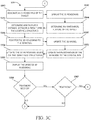
- a navigation phase may commence.
- the navigation phase may include the endobronchial navigation of the LG 92 and/or the EBUS 62 of the system 100 to the target selected at step S310 via the pathway determined at step S312.
- a navigation plan is selected and loaded for display of the target and the pathway on the 3D model at step S314.
- the computing device 80 may cause a display device, such as display 206, to display the 3D model with the target and the pathway indicated thereon.
- the EM field generator 76 of the EM tracking system 70 generates an EM field about the patient's body, and in particular, about the patient's chest.
- the EM tracking system 70 detects a position of the EM sensor 94 in the EM field.
- the EM tracking system 70 then provides EM tracking data regarding the detected position of the EM sensor 94 to the computing device 80.
- the 3D model may then, at step S320, be registered with the patient's body, as described above.
- the 3D model generated at step S306 may not need to be registered with the patient's body because the first image data received at step S302 show the patient in the current position of the patient's body on the table 40.
- the 3D model is merely aligned with the patient's body, such as via the reference sensors 74 or other markers placed on the patient's body prior to obtaining the first image data.
- the computing device 80 determines a position of the LG 92 and/or EBUS 62 based on the EM tracking data received from the EM tracking system at step S318.
- the computing device 80 displays the tracked position of EM sensor 94 on the 3D model, thereby providing an indication of the position of the LG 92 and/or EBUS 62 inside the patient's airways.
- the computing device 80 causes the display 206 to display the tracked position of the LG 92 and/or EBUS 62 on the 3D model.
- the computing device 80 determines whether the LG 92 and/or EBUS 62 have reached the target. For example, the computing device 80 may determine whether the EM tracking data received from the EM tracking system indicates that the EM sensor 94 is proximate the position of the target selected at step S310. If the computing device 80 determines that the LG 92 and/or EBUS 62 have not reached the target ("NO" at step S326), processing returns to step S322. Alternatively, if the computing device 80 determines that the LG 92 and/or EBUS 62 have reached the target ("YES" at step S326), processing proceeds to step S328.
- the computing device 80 provides guidance for positioning the LG 92 and/or EBUS 62 relative to the target.
- the computing device 80 may cause the display 206 to display visual guidance for positing the LG 92 and/or EBUS 62 relative to the target.
- the guidance may include visual and/or audible instructions for positioning the LG 92 and/or EBUS 62.
- the computing device 80 determines whether the LG 92 and/or EBUS 62 are correctly positioned relative to the target.
- the computing device 80 may determine whether the EM tracking data received from the EM tracking system 70 indicates that the EM sensor 94 is at a correct position and/or orientation (referred to hereinafter as a "pose") relative to the target.
- a correct position and/or orientation referred to hereinafter as a "pose
- step S330 If the computing device 80 determines that the LG 92 and/or EBUS 62 is not correctly positioned relative to the target ("NO" at step S330), processing returns to step S328. Alternatively, if the computing device 80 determines that the LG 92 and/or EBUS 62 are correctly positioned relative to the target ("YES" at step S330), processing proceeds to step S332. After the computing device 80 determines that the LG 92 is correctly positioned relative to the target, the computing device 80 may provide guidance for removing the LG 92 from the EWC 96 and inserting the EBUS 62 into the EWC 96. Alternatively, if the EBUS 62 was used to navigate to the target, no tool exchange is necessary at this stage.
- the computing device 80 receives ultrasound image data of the target.
- the ultrasound image data may be captured by the EBUS 62 and may be provided to the computing device 80 via an ultrasound workstation and/or a direct connection between the EBUS 62 and the computing device 80.
- the computing device 80 determines whether ultrasound imaging of the target is complete. For example, the computing device 80 may receive input from the clinician indicating that the ultrasound imaging is complete. Additionally or alternatively, the computing device 80 may determine whether the entire target can be identified in the ultrasound image data in order to determine whether the ultrasound imaging of the target is complete.
- step S336 the computing device 80 provides guidance for moving the EBUS 62 relative to the target.
- the computing device 80 may cause the display 206 to display visual guidance for moving the EBUS 62 relative to the target. Thereafter, processing returns to step S332.
- step S338 the computing device 80 processes the ultrasound image data received at step S332 to remove artifacts from the ultrasound image data.
- the computing device 80 may further process the ultrasound image data to identify the target in the ultrasound image data.
- step S340 the computing device 80 generates a 3D rendering based on the target based on the ultrasound image data.
- the computing device 80 may use various image processing algorithms, including segmentation and region growing algorithms, to identify the target in the ultrasound image data and stitch together various portions of the ultrasound image data to generate a 3D rendering of the target.
- the computing device 80 may display the 3D rendering of the target at step S342.
- the computing device 80 may cause the display 206 to display the 3D rendering of the target.
- the computing device 80 may further determine, at step S344, one or more anatomical features of the target based on the ultrasound image data and/or the 3D rendering of the target.
- the anatomical features may include a size, a shape, a margin, an echogenicity, a central hilar structure, and/or a coagulation necrosis characteristic of the target.
- the computing device 80 may determine, at step S346, a distance, direction, and/or interaction between the target and one or more of the structures identified at step S304. The computing device 80 may then cause the display 206 to display an indication of the distance, direction, and/or interaction between the target and the structures identified at step S304.
- the computing device 80 registers the 3D rendering of the target with the 3D model.
- the computing device 80 registers the 3D rendering of the target with the 3D model based on the position of the EBUS 62 when the ultrasound image data were obtained, as determined based on the position of the EM sensor 94.
- the computing device 80 may then, at step S350, update and/or enhance the portion of the 3D model corresponding to the area for which ultrasound image data were received.
- the computing device 80 may process the ultrasound image data to identify structures in the ultrasound image data that are imaged with greater detail or clarity than the first image data received at step S302.
- the computing device 80 may then update and/or enhance the 3D model based on such structures.
- the computing device 80 may, at step S352, update the registration of the 3D model to the patient's body based on the ultrasound image data received at step S332 and/or the structures identified therein.
- the computing device 80 may further, at step S354, update and/or enhance the 3D rendering of the target based on the 3D model, the first image data, and/or the structures identified at step S304.
- the computing device 80 may then, at step S356, display the updated 3D rendering of the target.
- the computing device 80 may cause the display 206 to display the updated 3D rendering in conjunction with or separate from the 3D model.
- the computing device 80 determines whether treatment of the target is needed. In embodiments, the computing device 80 determines whether treatment of the target is needed based on input provided by the clinician, such as via input device 210. In other embodiments, the computing device 80 may also determine whether treatment of the target is needed based on the predetermined diagnostic and/or treatment plan, and/or based on the anatomical feature of the target determined at step S344. If the computing device 80 determines that treatment of the target is needed ("YES" at block 358), processing proceeds to block S360.
- the computing device 80 determines whether the treatment of the target is to be performed now. In embodiments, the computing device 80 determines whether the treatment of the target is to be performed now based on input provided by the clinician, such as via input device 210. In other embodiments, the computing device 80 determines whether the treatment is to be performed now based on the predetermined diagnostic and/or treatment plan and/or based on the position of the EBUS 62 relative to the target. For example, the EBUS 62 may be positioned in a lumen or pose that is favorable for capturing the ultrasound image data, but may not be favorable for performing treatment of the target. Other considerations that may affect the determination of whether the treatment is the be performed now includes requirements for tool exchanges, time constraints, and/or additional navigation or positioning required.
- step S360 If the computing device 80 determines that the treatment is to be performed now ("YES” at step S360), processing proceeds to step S368. Alternatively, if the computing device 80 determines that the treatment is not needed ("NO” at step S358), or that the treatment is not to be performed now ("NO” at step S360), processing proceeds to step S362, where the computing device 80 displays the additional targets. In embodiments, the computing device 80 may cause the display 206 to a view of the 3D model showing the additional targets. For example, the additional targets may be highlighted and/or displayed with a different characteristic, such as a different color, than targets that have already been imaged.
- one or more regions of the 3D model may be displayed with a different characteristic, such as a different color, to indicate that there are additional targets to be imaged in those regions of the 3D model.
- the computing device 80 selects (automatically, semi-automatically, or manually) a next target.
- the next target may be selected based on the predetermined diagnosis and/or treatment plan, based on its proximity to the previous target, based on its accessibility from the current position of the EBUS 62, etc.
- the computing device 80 determines a pathway from the current position of the EBUS 62 to the next target.
- the computing device 80 may further cause the display 206 to display the pathway to the next target on the 3D model. Thereafter, processing returns to step S322.
- the computing device 80 determines whether the treatment tool is in the correct pose relative to the target to perform the treatment. For example, the computing device 80 may determine whether the EM tracking data received from the EM tracking system 70 indicates that the EM sensor 94 is in the correct pose relative to the target to perform the treatment. In embodiments where a biopsy tool separate from the EBUS 62 is used, or where a different type of treatment tool, such as the ablation tool 64, is needed, a tool exchange may be required. If the computing device 80 determines that the treatment tool is not in the correct pose relative to the target ("NO" at step S368), processing proceeds to step S384, where the computing device 80 determines a pathway to the target and/or guidance for manipulating the treatment tool into the correct pose relative to the target. Thereafter, at step S386, the computing device 80 displays the pathway and/or guidance determined at step S384, such as via the display 206. Then, processing returns to step S368.
- step S368 determines that the treatment tool is correctly positioned relative to the target to perform the treatment ("YES" at step S368), processing proceeds to step S370.
- the computing device 80 then tracks the position of the treatment tool, based on EM tracking data received from the EM tracking system 70, as the treatment tool is navigated to the biopsy target, and displays the current position of the treatment tool on the 3D model.
- the computing device 80 displays a view of the 3D rendering showing the position of the treatment tool relative to the target.
- the computing device 80 may cause the display 206 to display a view of the 3D rendering showing the pose of the treatment tool relative to the target and any interaction between the treatment tool and the target.
- a view of the 3D model may be displayed showing the pose of an EBUS 508 relative to a target 516, and interaction between a biopsy needle 512 and the target 516.
- the computing device 80 marks the position where the treatment was performed on the 3D model and/or the 3D rendering of the target. For example, the computing device 80 may place a digital marker on the 3D model and/or the 3D rendering of the target indicating the exact pose of the EBUS 62 and/or the biopsy tool when the biopsy was performed. Alternatively, if the treatment is an ablation procedure, the computing device may mark the pose of the ablation tool 64 when the ablation procedure was performed on the 3D model. The marker may later be updated with diagnosis information once the tissue sample has been analyzed or once additional diagnostic or treatment data is available.
- the computing device 80 determines a trajectory of the treatment tool. For example, the computing device 80 may determine, based on the EM tracking data received from the EM tracking system 70, the direction in which the EBUS 62 and/or the biopsy tool will move if the EBUS 62 is further extended in the current trajectory. The computing device 80 may further determine based on the trajectory whether additional treatment locations of the current target are reachable along the current trajectory of the treatment tool. The computing device 80 may then display the trajectory of the treatment tool on the 3D model and/or the 3D rendering of the target.
- the computing device 80 determines (automatically, semi-automatically, or manually) whether additional treatment is needed at the current target. For example, the computing device 80 may determine whether another biopsy sample is needed at the current target or whether additional ablation is needed. If the computing device 80 determines that additional treatment is needed at the current target ("YES" at step S376), processing returns to step S368. Alternatively, if the computing device 80 determines that additional treatment is not needed at the current target ("NO" at step S376), processing proceeds to step S378.
- the computing device 80 determines whether there are additional targets requiring treatment. For example, the computing device 80 may determine whether there are additional targets requiring treatment based on input provided by the clinician, and/or based on the predetermined diagnostic and/or treatment plan. If the computing device determines that there are additional targets requiring treatment ("YES" at step S378), processing proceeds to step S382, where the computing device 80 selects the next treatment target, whereafter processing proceeds to step S284. Alternatively, if the computing device 80 determines that there are no additional treatment targets remaining ("NO" at step S378), processing proceeds to step S388.
- the computing device 80 determines whether there are additional targets remaining that require imaging. In embodiments, the computing device 80 may determine whether there are additional targets remaining that require imaging based on input provided by the clinician, and/or based on the predetermined diagnostic and/or treatment plan. If the computing device determines that there are additional targets remaining that require imaging ("YES" at step S388), processing returns to step S362. Alternatively, if the computing device determines that there are no additional targets remaining that require imaging,("NO" at step S388), the method 300 ends.
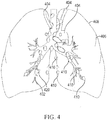
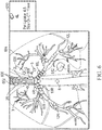
- FIG. 4 shows an illustrative graphical user interface (GUI) including a 3D model of a patient's chest showing portions of the bronchial and vascular trees, as well as various lymph nodes and the pleura and fissures of the patient's lungs, as described above.
- the 3D model includes a bronchial tree 402 showing the trachea and the various bifurcations of the airways, and the pleural surfaces 406 and fissures 408 of the patient's lungs.
- the 3D model further includes vascular structures 404, such as major arteries and veins, as well as lymph nodes 410, and a selected target location 420.
- FIG. 5 shows another illustrative GUI that may be displayed during various steps of the method 300.
- FIG. 5 shows a view of the 3D model including portions of the patient's bronchial tree 502, vascular tree 504, and lymph nodes 506.
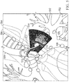
- FIG. 5 also shows a representation of the EBUS 508 including an ultrasound sensor 510 and a biopsy needle 512. Ultrasound images 514 captured by the ultrasound sensor are shown overlaid onto the 3D model, with a 3D rendering of the target 516 displayed thereon.
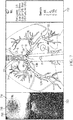
- FIG. 6 shows yet another illustrative GUI that may be displayed during various steps of the method 300. Similar to FIGS. 4 and 5 , FIG. 6 also shows a view of the 3D model including the patient's trachea 602 and airway tree 604, along with the positions of a plurality of lymph nodes 606 displayed thereon. In embodiments, the lymph nodes 606 are overlaid onto the 3D model. One of the lymph nodes 608 may be selected and may be displayed with a different visual characteristic (such as a different color). Additional details, such as anatomical features or characteristics, regarding the selected lymph node 608 may be displayed in a view 610. The additional details may include a PET uptake, a size, etc. Additional structures, such as one or more lesions 612 may also be displayed on the view of the 3D model.
- FIG. 7 shows another view of the GUI of FIG. 6 showing additional features and/or details that may be displayed during various steps of the method 300. Additional features of FIG. 7 that were described above with reference to FIG. 6 will not be described again for purpose of brevity.
- FIG. 7 further includes a bronchoscopic view 714 showing live video images received from an imaging device included in the bronchoscope 50.
- the bronchoscopic view 714 may be overlaid with a label 716 indicating the portion of the bronchial tree that is displayed in the bronchoscopic view 714, as well as an overlay 718 indicating the position of various structures, such as the selected lymph node 608, relative to the shown airway tree.
- FIG. 7 further shows a view of the ultrasound image data 720 captured by the EBUS 62. Additionally, FIG. 7 may show a list 722 of lymph nodes for which treatment is required.
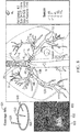
- FIG. 8 shows yet another view of the GUI of FIG. 6 and 7 showing additional features and/or details that may be displayed during various steps of the method 300.
- FIG. 8 shows a view 824 of the 3D rendering 826 of a selected lymph node 608.
- the view 824 of the 3D rendering 826 may show markers 828 indicating positions where previous treatments were performed.
- the view 824 of the 3D rendering 826 may show markers representing the pose of a biopsy needle when a tissue sample was obtained.
- FIG. 8 further shows a view 830 of the ultrasound image data captured by the EBUS 62, where the ultrasound image data is augmented with indicators 832 representing the positions of identified structures in the ultrasound image data.
- FIG. 9 shows a view of a GUI that may be shown during or after the various steps of the method 300.
- FIG. 9 includes a report 934 providing details of one or more selected lymph nodes 608, including the 3D renderings 826 of the selected lymph nodes 608, as well as the additional details 610 regarding the selected lymph nodes, including a PET uptake, a size of the selected lymph node 608 on a CT image, a size of the selected lymph node on an ultrasound image, an indicating of whether and/or how many times the selected lymph node 608 has been treated or sampled, coverage of the treatment, a malignancy risk of the selected lymph node 608, and/or a suspicion of being diseased and/or requiring treatment.
Landscapes
- Health & Medical Sciences (AREA)
- Life Sciences & Earth Sciences (AREA)
- Engineering & Computer Science (AREA)
- Surgery (AREA)
- Veterinary Medicine (AREA)
- Nuclear Medicine, Radiotherapy & Molecular Imaging (AREA)
- Public Health (AREA)
- General Health & Medical Sciences (AREA)
- Biomedical Technology (AREA)
- Heart & Thoracic Surgery (AREA)
- Medical Informatics (AREA)
- Molecular Biology (AREA)
- Animal Behavior & Ethology (AREA)
- Pathology (AREA)
- Biophysics (AREA)
- Physics & Mathematics (AREA)
- Radiology & Medical Imaging (AREA)
- Gynecology & Obstetrics (AREA)
- Human Computer Interaction (AREA)
- Robotics (AREA)
- Oral & Maxillofacial Surgery (AREA)
- Computer Vision & Pattern Recognition (AREA)
- Vascular Medicine (AREA)
- Apparatus For Radiation Diagnosis (AREA)
- Ultra Sonic Daignosis Equipment (AREA)
Applications Claiming Priority (2)
| Application Number | Priority Date | Filing Date | Title |
|---|---|---|---|
| US201862631250P | 2018-02-15 | 2018-02-15 | |
| US16/269,821 US20190246946A1 (en) | 2018-02-15 | 2019-02-07 | 3d reconstruction and guidance based on combined endobronchial ultrasound and magnetic tracking |
Publications (2)
| Publication Number | Publication Date |
|---|---|
| EP3527159A2 true EP3527159A2 (fr) | 2019-08-21 |
| EP3527159A3 EP3527159A3 (fr) | 2020-03-18 |
Family
ID=65685117
Family Applications (1)
| Application Number | Title | Priority Date | Filing Date |
|---|---|---|---|
| EP19157516.6A Withdrawn EP3527159A3 (fr) | 2018-02-15 | 2019-02-15 | Reconstruction 3d et guidage basé sur un suivi combiné d'ultrasons endobronchique et magnétique |
Country Status (2)
| Country | Link |
|---|---|
| US (1) | US20190246946A1 (fr) |
| EP (1) | EP3527159A3 (fr) |
Families Citing this family (7)
| Publication number | Priority date | Publication date | Assignee | Title |
|---|---|---|---|---|
| CN111095263A (zh) | 2017-06-26 | 2020-05-01 | 纽约州立大学研究基金会 | 用于虚拟胰造影术的系统、方法和计算机可访问介质 |
| US12605150B2 (en) | 2019-07-16 | 2026-04-21 | Prana Thoracic, Inc. | Systems, devices, and methods for coring tissue |
| US11931111B2 (en) | 2019-09-09 | 2024-03-19 | Covidien Lp | Systems and methods for providing surgical guidance |
| WO2021058288A1 (fr) * | 2019-09-26 | 2021-04-01 | Koninklijke Philips N.V. | Orientation de plan ultrasonore automatique en boucle fermée pour localisation de cible en imagerie ultrasonore et dispositifs, systèmes et procédés associés |
| US12521168B2 (en) | 2020-06-08 | 2026-01-13 | Prana Thoracic, Inc. | Tissue resection control systems and methods |
| US20210393332A1 (en) * | 2020-06-22 | 2021-12-23 | Ethicon, Inc. | Methods and devices for navigating a tissue resection device |
| US20220175457A1 (en) * | 2022-02-06 | 2022-06-09 | Real Image Technology Co., Ltd | Endoscopic image registration system for robotic surgery |
Citations (10)
| Publication number | Priority date | Publication date | Assignee | Title |
|---|---|---|---|---|
| US6188355B1 (en) | 1997-12-12 | 2001-02-13 | Super Dimension Ltd. | Wireless six-degree-of-freedom locator |
| WO2001067035A1 (fr) | 2000-03-09 | 2001-09-13 | Super Dimension Ltd. | Reperage d'objet au moyen d'un detecteur unique ou d'une paire de detecteurs |
| US6833814B2 (en) | 1998-08-02 | 2004-12-21 | Super Dimension Ltd. | Intrabody navigation system for medical applications |
| US20110085720A1 (en) | 2009-05-14 | 2011-04-14 | Superdimension, Ltd. | Automatic Registration Technique |
| US20160005193A1 (en) | 2014-07-02 | 2016-01-07 | Covidien Lp | System and method for segmentation of lung |
| US20160000356A1 (en) | 2014-07-02 | 2016-01-07 | Covidien Lp | Real-time automatic registration feedback |
| US9247992B2 (en) | 2012-08-07 | 2016-02-02 | Covidien, LP | Microwave ablation catheter and method of utilizing the same |
| US20160038248A1 (en) | 2014-08-11 | 2016-02-11 | Covidien Lp | Treatment procedure planning system and method |
| US9459770B2 (en) | 2013-03-15 | 2016-10-04 | Covidien Lp | Pathway planning system and method |
| US9770216B2 (en) | 2014-07-02 | 2017-09-26 | Covidien Lp | System and method for navigating within the lung |
Family Cites Families (15)
| Publication number | Priority date | Publication date | Assignee | Title |
|---|---|---|---|---|
| US6019724A (en) * | 1995-02-22 | 2000-02-01 | Gronningsaeter; Aage | Method for ultrasound guidance during clinical procedures |
| WO2002041752A2 (fr) * | 2000-11-24 | 2002-05-30 | U-Systems, Inc. | Procede et systeme d'analyse instantanee de prelevement de biopsie |
| US6892090B2 (en) * | 2002-08-19 | 2005-05-10 | Surgical Navigation Technologies, Inc. | Method and apparatus for virtual endoscopy |
| WO2004109330A1 (fr) * | 2003-06-10 | 2004-12-16 | Koninklijke Philips Electronics, N.V. | Interface utilisateur pour un systeme d'imagerie ultrasonore tridimensionnelle en couleurs |
| US7037263B2 (en) * | 2003-08-20 | 2006-05-02 | Siemens Medical Solutions Usa, Inc. | Computing spatial derivatives for medical diagnostic imaging methods and systems |
| US20080146919A1 (en) * | 2006-09-29 | 2008-06-19 | Estelle Camus | Method for implanting a cardiac implant with real-time ultrasound imaging guidance |
| US8821376B2 (en) * | 2007-03-12 | 2014-09-02 | David Tolkowsky | Devices and methods for performing medical procedures in tree-like luminal structures |
| US8625869B2 (en) * | 2010-05-21 | 2014-01-07 | Siemens Medical Solutions Usa, Inc. | Visualization of medical image data with localized enhancement |
| EP2807978A1 (fr) * | 2013-05-28 | 2014-12-03 | Universität Bern | Procédé et système d'acquisition en 3D d'images ultrasonores |
| US9949700B2 (en) * | 2015-07-22 | 2018-04-24 | Inneroptic Technology, Inc. | Medical device approaches |
| US10328195B2 (en) * | 2016-05-03 | 2019-06-25 | Covidien Lp | Vascular isolation systems and methods |
| US10327853B2 (en) * | 2016-05-10 | 2019-06-25 | Covidien Lp | System and method of performing treatment along a lumen network |
| EP3469553A1 (fr) * | 2016-06-10 | 2019-04-17 | Koninklijke Philips N.V. | Systèmes et procédés pour générer des images en mode b à partir de données ultrasonores 3d |
| AU2017301435B2 (en) * | 2016-07-25 | 2022-07-14 | Magic Leap, Inc. | Imaging modification, display and visualization using augmented and virtual reality eyewear |
| US11504154B2 (en) * | 2016-07-28 | 2022-11-22 | The United States Of America, As Represented By The Secretary, Department Of Health And Human Services | Transperineal imaging-guided prostate needle placement |
-
2019
- 2019-02-07 US US16/269,821 patent/US20190246946A1/en not_active Abandoned
- 2019-02-15 EP EP19157516.6A patent/EP3527159A3/fr not_active Withdrawn
Patent Citations (11)
| Publication number | Priority date | Publication date | Assignee | Title |
|---|---|---|---|---|
| US6188355B1 (en) | 1997-12-12 | 2001-02-13 | Super Dimension Ltd. | Wireless six-degree-of-freedom locator |
| US6833814B2 (en) | 1998-08-02 | 2004-12-21 | Super Dimension Ltd. | Intrabody navigation system for medical applications |
| WO2001067035A1 (fr) | 2000-03-09 | 2001-09-13 | Super Dimension Ltd. | Reperage d'objet au moyen d'un detecteur unique ou d'une paire de detecteurs |
| US20110085720A1 (en) | 2009-05-14 | 2011-04-14 | Superdimension, Ltd. | Automatic Registration Technique |
| US9247992B2 (en) | 2012-08-07 | 2016-02-02 | Covidien, LP | Microwave ablation catheter and method of utilizing the same |
| US9259269B2 (en) | 2012-08-07 | 2016-02-16 | Covidien Lp | Microwave ablation catheter and method of utilizing the same |
| US9459770B2 (en) | 2013-03-15 | 2016-10-04 | Covidien Lp | Pathway planning system and method |
| US20160005193A1 (en) | 2014-07-02 | 2016-01-07 | Covidien Lp | System and method for segmentation of lung |
| US20160000356A1 (en) | 2014-07-02 | 2016-01-07 | Covidien Lp | Real-time automatic registration feedback |
| US9770216B2 (en) | 2014-07-02 | 2017-09-26 | Covidien Lp | System and method for navigating within the lung |
| US20160038248A1 (en) | 2014-08-11 | 2016-02-11 | Covidien Lp | Treatment procedure planning system and method |
Also Published As
| Publication number | Publication date |
|---|---|
| EP3527159A3 (fr) | 2020-03-18 |
| US20190246946A1 (en) | 2019-08-15 |
Similar Documents
| Publication | Publication Date | Title |
|---|---|---|
| US12318151B2 (en) | Integration of multiple data sources for localization and navigation | |
| US12064280B2 (en) | System and method for identifying and marking a target in a fluoroscopic three-dimensional reconstruction | |
| US11622815B2 (en) | Systems and methods for providing proximity awareness to pleural boundaries, vascular structures, and other critical intra-thoracic structures during electromagnetic navigation bronchoscopy | |
| US11925493B2 (en) | Visualization, navigation, and planning with electromagnetic navigation bronchoscopy and cone beam computed tomography integrated | |
| US11547377B2 (en) | System and method for navigating to target and performing procedure on target utilizing fluoroscopic-based local three dimensional volume reconstruction | |
| US20190247127A1 (en) | 3d reconstruction and guidance based on combined endobronchial ultrasound and magnetic tracking | |
| US12539177B2 (en) | Systems and methods for visualizing navigation of medical devices relative to targets | |
| CN110741414B (zh) | 用于使用实时二维荧光镜检查数据识别、标记和导航到靶标的系统和方法 | |
| EP3527159A2 (fr) | Reconstruction 3d et guidage basé sur un suivi combiné d'ultrasons endobronchique et magnétique | |
| CN112386336A (zh) | 用于进行初始配准的荧光-ct成像的系统和方法 | |
| EP3522112B1 (fr) | Cartographie d'étalement de maladie | |
| US20200046433A1 (en) | Identification and notification of tool displacement during medical procedure | |
| CN115843232A (zh) | 用于目标覆盖的缩放检测和荧光镜移动检测 | |
| CN120018825A (zh) | 用于确认医疗装置相对于目标的位置或取向的系统和方法 | |
| CN119997895A (zh) | 在可视化或机器人系统中移动医疗工具与目标以获得更高产量的系统和方法 |
Legal Events
| Date | Code | Title | Description |
|---|---|---|---|
| PUAI | Public reference made under article 153(3) epc to a published international application that has entered the european phase |
Free format text: ORIGINAL CODE: 0009012 |
|
| STAA | Information on the status of an ep patent application or granted ep patent |
Free format text: STATUS: REQUEST FOR EXAMINATION WAS MADE |
|
| 17P | Request for examination filed |
Effective date: 20190215 |
|
| AK | Designated contracting states |
Kind code of ref document: A2 Designated state(s): AL AT BE BG CH CY CZ DE DK EE ES FI FR GB GR HR HU IE IS IT LI LT LU LV MC MK MT NL NO PL PT RO RS SE SI SK SM TR |
|
| AX | Request for extension of the european patent |
Extension state: BA ME |
|
| PUAL | Search report despatched |
Free format text: ORIGINAL CODE: 0009013 |
|
| AK | Designated contracting states |
Kind code of ref document: A3 Designated state(s): AL AT BE BG CH CY CZ DE DK EE ES FI FR GB GR HR HU IE IS IT LI LT LU LV MC MK MT NL NO PL PT RO RS SE SI SK SM TR |
|
| AX | Request for extension of the european patent |
Extension state: BA ME |
|
| RIC1 | Information provided on ipc code assigned before grant |
Ipc: A61B 34/20 20160101AFI20200207BHEP |
|
| RBV | Designated contracting states (corrected) |
Designated state(s): AL AT BE BG CH CY CZ DE DK EE ES FI FR GB GR HR HU IE IS IT LI LT LU LV MC MK MT NL NO PL PT RO RS SE SI SK SM TR |
|
| STAA | Information on the status of an ep patent application or granted ep patent |
Free format text: STATUS: EXAMINATION IS IN PROGRESS |
|
| 17Q | First examination report despatched |
Effective date: 20230321 |
|
| STAA | Information on the status of an ep patent application or granted ep patent |
Free format text: STATUS: THE APPLICATION IS DEEMED TO BE WITHDRAWN |
|
| 18D | Application deemed to be withdrawn |
Effective date: 20250923 |