EP3527281A1 - Umkehrosmosesystem und methode mit mischung von zulauf und permeate zur anpassung des gehaltes von gelösten feststoffteilchen - Google Patents
Umkehrosmosesystem und methode mit mischung von zulauf und permeate zur anpassung des gehaltes von gelösten feststoffteilchen Download PDFInfo
- Publication number
- EP3527281A1 EP3527281A1 EP19158160.2A EP19158160A EP3527281A1 EP 3527281 A1 EP3527281 A1 EP 3527281A1 EP 19158160 A EP19158160 A EP 19158160A EP 3527281 A1 EP3527281 A1 EP 3527281A1
- Authority
- EP
- European Patent Office
- Prior art keywords
- water
- cartridge
- flowrate
- water line
- unfiltered
- Prior art date
- Legal status (The legal status is an assumption and is not a legal conclusion. Google has not performed a legal analysis and makes no representation as to the accuracy of the status listed.)
- Ceased
Links
Images


Classifications
-
- B—PERFORMING OPERATIONS; TRANSPORTING
- B01—PHYSICAL OR CHEMICAL PROCESSES OR APPARATUS IN GENERAL
- B01D—SEPARATION
- B01D61/00—Processes of separation using semi-permeable membranes, e.g. dialysis, osmosis or ultrafiltration; Apparatus, accessories or auxiliary operations specially adapted therefor
- B01D61/02—Reverse osmosis; Hyperfiltration ; Nanofiltration
- B01D61/12—Controlling or regulating
-
- C—CHEMISTRY; METALLURGY
- C02—TREATMENT OF WATER, WASTE WATER, SEWAGE, OR SLUDGE
- C02F—TREATMENT OF WATER, WASTE WATER, SEWAGE, OR SLUDGE
- C02F1/00—Treatment of water, waste water, or sewage
- C02F1/44—Treatment of water, waste water, or sewage by dialysis, osmosis or reverse osmosis
- C02F1/441—Treatment of water, waste water, or sewage by dialysis, osmosis or reverse osmosis by reverse osmosis
-
- B—PERFORMING OPERATIONS; TRANSPORTING
- B01—PHYSICAL OR CHEMICAL PROCESSES OR APPARATUS IN GENERAL
- B01D—SEPARATION
- B01D61/00—Processes of separation using semi-permeable membranes, e.g. dialysis, osmosis or ultrafiltration; Apparatus, accessories or auxiliary operations specially adapted therefor
- B01D61/02—Reverse osmosis; Hyperfiltration ; Nanofiltration
- B01D61/08—Apparatus therefor
-
- C—CHEMISTRY; METALLURGY
- C02—TREATMENT OF WATER, WASTE WATER, SEWAGE, OR SLUDGE
- C02F—TREATMENT OF WATER, WASTE WATER, SEWAGE, OR SLUDGE
- C02F1/00—Treatment of water, waste water, or sewage
- C02F1/008—Control or steering systems not provided for elsewhere in subclass C02F
-
- B—PERFORMING OPERATIONS; TRANSPORTING
- B01—PHYSICAL OR CHEMICAL PROCESSES OR APPARATUS IN GENERAL
- B01D—SEPARATION
- B01D2311/00—Details relating to membrane separation process operations and control
- B01D2311/04—Specific process operations in the feed stream; Feed pretreatment
-
- B—PERFORMING OPERATIONS; TRANSPORTING
- B01—PHYSICAL OR CHEMICAL PROCESSES OR APPARATUS IN GENERAL
- B01D—SEPARATION
- B01D2311/00—Details relating to membrane separation process operations and control
- B01D2311/08—Specific process operations in the concentrate stream
-
- B—PERFORMING OPERATIONS; TRANSPORTING
- B01—PHYSICAL OR CHEMICAL PROCESSES OR APPARATUS IN GENERAL
- B01D—SEPARATION
- B01D2311/00—Details relating to membrane separation process operations and control
- B01D2311/25—Recirculation, recycling or bypass, e.g. recirculation of concentrate into the feed
- B01D2311/253—Bypassing of feed
- B01D2311/2531—Bypassing of feed to permeate side
-
- B—PERFORMING OPERATIONS; TRANSPORTING
- B01—PHYSICAL OR CHEMICAL PROCESSES OR APPARATUS IN GENERAL
- B01D—SEPARATION
- B01D2313/00—Details relating to membrane modules or apparatus
- B01D2313/18—Specific valves
-
- B—PERFORMING OPERATIONS; TRANSPORTING
- B01—PHYSICAL OR CHEMICAL PROCESSES OR APPARATUS IN GENERAL
- B01D—SEPARATION
- B01D2319/00—Membrane assemblies within one housing
- B01D2319/02—Elements in series
- B01D2319/025—Permeate series
-
- B—PERFORMING OPERATIONS; TRANSPORTING
- B01—PHYSICAL OR CHEMICAL PROCESSES OR APPARATUS IN GENERAL
- B01D—SEPARATION
- B01D2319/00—Membrane assemblies within one housing
- B01D2319/06—Use of membranes of different materials or properties within one module
-
- B—PERFORMING OPERATIONS; TRANSPORTING
- B01—PHYSICAL OR CHEMICAL PROCESSES OR APPARATUS IN GENERAL
- B01D—SEPARATION
- B01D61/00—Processes of separation using semi-permeable membranes, e.g. dialysis, osmosis or ultrafiltration; Apparatus, accessories or auxiliary operations specially adapted therefor
- B01D61/02—Reverse osmosis; Hyperfiltration ; Nanofiltration
- B01D61/025—Reverse osmosis; Hyperfiltration
-
- B—PERFORMING OPERATIONS; TRANSPORTING
- B01—PHYSICAL OR CHEMICAL PROCESSES OR APPARATUS IN GENERAL
- B01D—SEPARATION
- B01D61/00—Processes of separation using semi-permeable membranes, e.g. dialysis, osmosis or ultrafiltration; Apparatus, accessories or auxiliary operations specially adapted therefor
- B01D61/02—Reverse osmosis; Hyperfiltration ; Nanofiltration
- B01D61/04—Feed pretreatment
-
- C—CHEMISTRY; METALLURGY
- C02—TREATMENT OF WATER, WASTE WATER, SEWAGE, OR SLUDGE
- C02F—TREATMENT OF WATER, WASTE WATER, SEWAGE, OR SLUDGE
- C02F2201/00—Apparatus for treatment of water, waste water or sewage
- C02F2201/002—Construction details of the apparatus
- C02F2201/005—Valves
-
- C—CHEMISTRY; METALLURGY
- C02—TREATMENT OF WATER, WASTE WATER, SEWAGE, OR SLUDGE
- C02F—TREATMENT OF WATER, WASTE WATER, SEWAGE, OR SLUDGE
- C02F2201/00—Apparatus for treatment of water, waste water or sewage
- C02F2201/002—Construction details of the apparatus
- C02F2201/006—Cartridges
-
- C—CHEMISTRY; METALLURGY
- C02—TREATMENT OF WATER, WASTE WATER, SEWAGE, OR SLUDGE
- C02F—TREATMENT OF WATER, WASTE WATER, SEWAGE, OR SLUDGE
- C02F2209/00—Controlling or monitoring parameters in water treatment
- C02F2209/03—Pressure
-
- C—CHEMISTRY; METALLURGY
- C02—TREATMENT OF WATER, WASTE WATER, SEWAGE, OR SLUDGE
- C02F—TREATMENT OF WATER, WASTE WATER, SEWAGE, OR SLUDGE
- C02F2209/00—Controlling or monitoring parameters in water treatment
- C02F2209/10—Solids, e.g. total solids [TS], total suspended solids [TSS] or volatile solids [VS]
-
- C—CHEMISTRY; METALLURGY
- C02—TREATMENT OF WATER, WASTE WATER, SEWAGE, OR SLUDGE
- C02F—TREATMENT OF WATER, WASTE WATER, SEWAGE, OR SLUDGE
- C02F2209/00—Controlling or monitoring parameters in water treatment
- C02F2209/40—Liquid flow rate
-
- C—CHEMISTRY; METALLURGY
- C02—TREATMENT OF WATER, WASTE WATER, SEWAGE, OR SLUDGE
- C02F—TREATMENT OF WATER, WASTE WATER, SEWAGE, OR SLUDGE
- C02F2301/00—General aspects of water treatment
- C02F2301/04—Flow arrangements
- C02F2301/043—Treatment of partial or bypass streams
Definitions
- Water filtration systems are frequently used in a variety of settings, including residential and commercial applications, in which the systems are designed to remove contaminants and other impurities from the water supply to provide filtered water to equipment and/or an end user.
- source water quality and pressure can vary in different locations, which requires unique filtration parameters tailored to the specific properties of the water being filtered and the level and quality of filtration desired by the end user.
- Some embodiments of the invention provide a reverse osmosis water filtration system including a housing having an inlet and an outlet, the inlet receiving untreated water from a water source.
- the system includes a pre-filter cartridge fluidly coupled to the inlet via an inlet water line.
- the system includes a reverse osmosis cartridge fluidly coupled to the pre-filter cartridge via a medial water line.
- the medial water line transports a first portion of pretreated water from the pre-filter cartridge to the reverse osmosis cartridge.
- the system includes a post treatment cartridge fluidly coupled to the reverse osmosis cartridge via the medial water line.
- the system includes an unfiltered water line having a flow restrictor and a blend valve. The unfiltered water line is fluidly coupled to the medial water line.
- the unfiltered water line receives a second portion of the pretreated water from the pre-filter cartridge.
- the system includes a blend water line fluidly coupled between the medial water line and the unfiltered water line.
- the blend water line transports to the outlet a blended water mixture including filtered water at a first flowrate from the reverse osmosis cartridge and unfiltered water at a second flowrate from the blend valve.
- the first flowrate and the second flowrate can be substantially equal.
- a reverse osmosis water filtration system for use with a water source as defined in claim 1.
- the flow restrictor adjusts the second flowrate.
- the second flowrate is controlled to be equal to the first flowrate.
- the pre-filter cartridge, the reverse osmosis cartridge, and the post treatment cartridge are in series with respect to one another.
- system further comprises a pump to increase a pressure of the pretreated water leaving the pre-filter cartridge and a solenoid valve upstream from the pump.
- the medial water line fluidly couples the pump with the reverse osmosis cartridge and the post treatment cartridge.
- the unfiltered water line fluidly couples the pump with the flow restrictor, a check valve, and the blend valve.
- the unfiltered water line includes a check valve downstream from the flow restrictor and upstream from the blend valve.
- the filtered water passes through the post treatment cartridge before mixing with the unfiltered water from the blend valve.
- the post treatment cartridge adds minerals to the filtered water.
- a retentate stream from the reverse osmosis cartridge exits via an outlet water line to a drain.
- the outlet water line includes a second flow restrictor configured to control a third flowrate of the retentate stream.
- the medial water line and the unfiltered water line are parallel with respect to one another.
- the method further comprises increasing a pressure of the pretreated water.
- the method further comprises sending the filtered water through a post treatment cartridge before combining with the unfiltered water.
- the first flowrate of the filtered water and the second flowrate of the unfiltered water are substantially equal before combining to produce the blended water mixture.
- the method further comprises monitoring total dissolved solids in the blended water mixture.
- the method further comprises maintaining a consistent total dissolved solids value by controlling the second flowrate to be substantially equal to the first flowrate.
- the method further comprises a user predetermining a total dissolved solids value of the blended water mixture.
- aspects and/or embodiments of the invention may comprise any one or more of the features described and defined herein.
- Features which are described in the context of separate aspects and/or embodiments of the invention may be used together, may be reomoved or replaced and/or be interchangable.
- features are, for brevity, described in the context of a single embodiment, these may also be provided separately or in any suitable subcombination.
- Features described in connection with the system may have corresponding features definable with respect to the method(s) and these embodiments are specifically envisaged.
- FIG. 1 illustrates a reverse osmosis (RO) water filtration system 20 according to some embodiments of the invention.
- the water filtration system 20 may include features that make the system unique to the commercial market (e.g., designed to be used by commercial entities).
- the water filtration system 20 is designed to be coupled with a storage tank (not shown), and includes a pump 22, and various flow conduits 24 that fluidly couple the pump 22 with the tank that stores end-use water that is blended to a desired degree.
- a blended water mixture may be stored in the tank and/or provided to an outlet 78, as shown in FIGS. 4 and 5 .
- the filtration system can include a housing (as shown and described with respect to FIGS. 8-10 ) to protect the components and fluid connections.
- the water filtration system 20 can offer a compact, efficient system that can be installed by a single person. The installation time for the water filtration system 20 may be reduced by minimal on-site assembly requirements.
- the water filtration system 20 may include disposable and recyclable filter cartridges 26, 28 and 30. In some embodiments, the cartridges may be changed periodically, for example, every 12 months. In other embodiments, the time the cartridges may be changed may be based on use.
- the reverse osmosis system 10 may include an integrated display and cover. The cover can include a shroud that is hinged on one side and pivots to expose the serviceable components.
- the water filtration system 20 can offer increased sustainability through low-water waste, low-energy use, recyclable filter cartridges, and modular/re-buildable components.
- the water filtration system 20 includes the pump 22, a pre-filter cartridge 26, a post-treatment cartridge 28, a reverse osmosis (RO) cartridge 30, and one or more head caps 32 that may be coupled with one or more of the pre-filter cartridge 26, the post-treatment cartridge 28, and/or the RO cartridge 30.
- the post-treatment cartridge 28 may be a mineral adding cartridge rather than a filtration cartridge.
- the post-treatment cartridge 28 is a 4CC post-filter that is capable of adding calcium or another mineral to the water as it passes through the post-treatment cartridge 28.
- the water filtration system 20 further includes a housing 40 to which the cartridges 26, 28, 30 are coupled. In some embodiments, the cartridges 26, 28 and 30 are connected in series through the housing 40.
- the pump 22 is also mechanically coupled within the housing 40. The pump 22 may be a booster pump.
- a power source 42 having a cord 44 and a solenoid valve 46.
- the power source 42 and the solenoid valve 46 are also coupled to the housing 40.
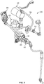
- a blend valve knob 48 is shown extending from the housing 40. The blend valve knob 48 is operable to manipulate one or more settings of a blend valve 60, as shown in FIG. 2 .
- FIG. 2 illustrates a pre-filter head cap 62 (which is one of the head caps 32) that is fluidly coupled to the solenoid valve 46.
- FIG. 2 also illustrates a first check valve 64 and a divider 66.
- the divider 66 combines water from two streams into a single stream.
- FIG. 2 also illustrates a pressure switch 68 connected to a controller (not shown).
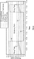
- FIGS. 4 and 5 schematically illustrate the flow paths of the water filtration system 20, with FIG. 5 showing pressure measurements within the various flow paths.
- FIG. 4 illustrates a water inlet 70, the pre-filter cartridge 26, the solenoid valve 46, the pump 22, the RO cartridge 30, the post-treatment cartridge 28, and the first check valve 64.
- These components of the water filtration system 20 may be provided in the order listed and as shown in FIG. 4 , i.e ., each component may be located upstream of the component it precedes as listed.
- the pre-filter cartridge 26, the solenoid valve 46, the pump 22, the RO cartridge 30, the post-treatment cartridge 28, and the first check valve 64 may be in series with respect to one another.
- the components of the water filtration system 20 shown in FIG. 4 are located within the housing 40. In other embodiments, some of the components may be located outside of the housing 40. Having the filtration and blending process occur within the housing has several advantages. First, the process results in a higher accuracy of the blend water mixture. Second, the water filtration system 20 maintains an internal pressure balance that also contributes to a blend product with a specific total dissolved solids (TDS) value.
- TDS total dissolved solids
- the pre-treatment filter cartridge 26, the solenoid valve 46, and the booster pump 22 may be provided along an inlet water line 72. Untreated water is transported to the pre-treatment filter cartridge 26 via the inlet water line 72. The untreated water passes through the pre-treatment filter cartridge 26 resulting in pretreated water. The pretreated water passes through the solenoid valve 46 to the booster pump 22 where the pressure of the pretreated water may be increased. In some embodiments, the pressure of the pretreated water may be 120 pounds per square inch (psi).
- the RO cartridge 30, the post-treatment cartridge 28, and the first check valve 64 may be provided along a medial water line 74. A first portion of the pretreated water may be sent to the RO cartridge 30 via the medial water line 74.
- Filtered water exits the RO cartridge 30 on the permeate side and is sent to the post-treatment cartridge 28.
- a retentate stream exits the RO cartridge 30 via a drain water line, passes through a second flow restrictor 88, and out of the system through a drain 86.
- FIG. 4 illustrates an unfiltered water line 80 intersecting the medial water line 74 between the pump 22 and the RO cartridge 30.
- the unfiltered water line 80 includes a first flow restrictor 82, a second check valve 84, and the blend valve 60.
- the first flow restrictor 82, the second check valve 84, and the blend valve 60 are provided in series with respect to one another, and the blend valve 60 is provided downstream of the second check valve 84.
- the first flow restrictor 82, the second check valve 84, and the blend valve 60 are also provided in parallel with respect to the RO cartridge 30 and the post-treatment cartridge 28.
- a second portion of the pretreated water from the pre-treatment cartridge 26 is sent to the first flow restrictor 82 via the unfiltered water line 80.
- the first flow restrictor 82 is configured to control the flowrate of unfiltered water in the unfiltered water line 80.
- the unfiltered water leaves the first flow restrictor 82 and passes through the second check valve 84 and the blend valve 60.
- the flowrate of the unfiltered water leaving the blend valve 60 may be different than the flowrate of the filtered water leaving the first check valve 64.
- the flowrate of the unfiltered water flowing through the blend valve 60 is the same or substantially equal to the flowrate of the filtered water flowing through the first check valve 64.
- the flowrates being the same or substantially equal has the advantage of improving the consistency of the total dissolved solids value of the blended water.
- a blend water line 90 is provided between the unfiltered water line 80 and the outlet water line 76.
- the blend water line 90 is provided downstream of the blend valve 60 and the first check valve 64 along the unfiltered water line 80 and the outlet water line 76, respectively.
- the blend water line 90 may be provided along a different portion of one or both of the unfiltered water line 80 and the outlet water line 76.
- the blended water line 90 may be provided before the filtered water passing through the post-treatment cartridge 28.
- the blend water line 90 may be provided after the filtered water passes through the post treatment cartridge 28.
- the pressure switch 68 is provided along the unfiltered water line 80.
- a tank (not shown) may be fluidly coupled with the unfiltered water line 80.
- the outlet water line 76 may be connected in series with the medial water line 74 and is coupled to the outlet 78 of the water filtration system 20.
- the filtered water from the RO cartridge 30 or the post-treatment cartridge 28 may be transported to the blend water line 90 to mix with the unfiltered water from the blend valve 60.
- the result is a blend water mixture having a particular TDS level.
- the TDS level may be predetermined by a user.
- the TDS level of the blend water mixture may be monitored before or after leaving the housing 40.
- a sensor (not shown) may detect the TDS level in the blended water mixture before or after leaving the housing 40.
- the TDS can be measured in milligram per liter (mg/L) and in parts per million (ppm).
- a user or technician can adjust the TDS of the water being dispensed to a value commonly used for certain types of beverages, such as coffee, tea, or beverage fountain drinks.
- first or pumped pressure 92 along a portion of the medial water line 74 and a portion of the unfiltered water line 80.
- second or blend line pressure 94 along a portion of the unfiltered water line 80 between the flow restrictor and the blend valve.
- second or blend line pressure 94 along a portion of the unfiltered water line 80 between the flow restrictor and the blend valve.
- RO pressure 96 along a portion of the medial water line 74 between the outlet of the RO cartridge 30 and the second check valve 84.
- fourth or outlet and tank pressure 98 along a portion of the unfiltered water line 80, the blend water line 90, and the outlet water line 76.
- the pressures along varying portions of the system may be similar or different, depending on whether the tank is being filled or emptied. The pressures are different due to the configuration of the pump 22, the blend valve 60, the RO cartridge 30, and the first check valve 64.
- one or more of the pumped pressure 92, the blend line pressure 94, the RO pressure 96, and the outlet and tank pressure 98 may be the same or different, or may increase or decrease at the same rate or different rates during different time periods, such as when the tank is being filled, or when the tank is being emptied.
- the pumped pressure 92 may steadily increase over time or may be generally constant, and may be between about 50 psi and about 110 psi, or between about 60 psi and about 100 psi, or about 90 psi.
- the blend line pressure 94, the RO pressure 96, and the pumped pressure 92 may also be steadily increasing, and may be between about 10 psi and about 70 psi, or between about 20 psi and about 60 psi, or about 25 psi.
- the pumped pressure 92, the blend line pressure 94, the RO pressure 96, and the outlet and tank pressure 98 may be increasing at the same rate, or may be increasing at different rates.
- the pumped pressure 92 may drop significantly from the aforementioned tank filling range to between about 5 psi and about 30 psi, or between about 10 psi and about 20 psi, or about 12 psi. Further, when the system 20 switches operation to begin emptying the tank, one or both of the blend line pressure 94 and the RO pressure 96 may drop from the aforementioned tank filling pressure ranges to between about 5 psi and about 30 psi, or between about 10 psi and about 20 psi, or about 12 psi when the tank is being emptied.
- the pumped pressure 92, the RO pressure 96, and/or the blend line pressure 94 may remain substantially constant, may slightly increase, or may slightly decrease until the water filtration system 20 enters into a different process, such as another filling tank process.
- the outlet and tank pressure 98 may slightly begin to decrease from between about 20 psi and about 60 psi or between about 30 psi and about 50 psi to between about 10 psi and about 50 psi or between about 20 psi and about 40 psi.
- the pumped pressure 92, the RO pressure 96, and the blend line pressure 94 may be approximately the same and may be generally constant, while during the same process, the outlet and tank pressure 98 may steadily decrease.
- the pumped pressure 92 may substantially increase from the aforementioned emptying tank pressure ranges to between about 50 psi and about 110 psi, or between about 60 psi and about 100 psi, or about 90 psi. Still further, when the system 20 changes from the emptying tank process to the filling tank process, the RO pressure 96 and the blend line pressure 94 may increase from the aforementioned emptying tank pressure ranges to between about 10 psi and about 70 psi, or between about 20 psi and about 60 psi, or about 25 psi.
- the outlet and tank pressure 98 may transition from decreasing to increasing. As mentioned previously with respect to the first filling tank process, all of the varying pressures may increase over the duration of the filling tank process.
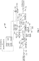
- FIG. 7 illustrates an alternative embodiment of a water filtration system 120.
- the differences between the water filtration system 120 of FIG. 7 and the water filtration system 20 of FIG. 4 are that a first check valve 164 is provided between an RO cartridge 130 and a post-treatment cartridge 128 and a blend water line 190 is provided between the first check valve 164 and the post-treatment cartridge 128.
- a loop is formed by (1) a portion of a unfiltered water line 180 including a first flow restrictor 182, a second check valve 184, and a blend valve 160; (2) the blend water line 190; and (3) a portion of a medial water line 174 including the RO cartridge 130 and the first check valve 164.
- water flows into the water inlet 70/170, along the inlet water line 72/172, and into the pre-filter cartridge 26/126.
- the water then flows through the solenoid valve 46/146 when the solenoid valve is in an "open" configuration.
- Water then flows into the booster pump 22/122, and a portion may be directed toward the medial water line 74/174, and/or the unfiltered water line 80/180.
- Water that is directed to the unfiltered water line 80/180 passes through the first flow restrictor 82/182, the second check valve 84/184, and the blend valve 60/160. Water in the unfiltered water line 80/180 is then either directed to the tank past the pressure switch 68/168, or is directed to the blend water line 90/190.
- water that is directed to the medial water line 74 passes through the RO cartridge 30, the post-treatment cartridge 28, and the first check valve 64 before either exiting the water filtration system 20 via the outlet water line 76 to the outlet 78 or through the blend water line 90 toward the tank.
- water that is directed to the medial water line 174 passes through the RO cartridge 130, through the first check valve 164, and is directed to either the blend water line 190 toward the tank, or is directed through the post-treatment cartridge 128 along the outlet water line 176 and to the outlet 178.
- waste water can also drain from the RO cartridge 30/130 through the second flow restrictor 88/188 to the drain 86/186.
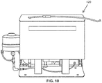
- FIGS. 8-10 illustrate external components of embodiments of housings of the water filtration system 20/120.
- the housings 220, 320 and 420 surround the components of the water filtration system 20/120.
- the water filtration system 20/120 may be installed by mounting on a wall. In some embodiments, the water filtration system 20/120 may be placed on a countertop. In other embodiments, the water filtration system 20/120 may be installed by placing the system under a counter.
- the water filtration system 20/120 may be used in numerous settings and may be secured to a variety of surfaces.
- Embodiments of the invention include the use of a small orifice, i.e ., a flow restrictor, in the unfiltered water line allowing the flowrates of the filtered water and the RO water to be balanced. Once the flowrates are balanced, the water that flows through the RO cartridge 30 and through the unfiltered water line 80/180 is mixed to achieve a desired level of mineral content.
- the addition of the first flow restrictor 82/182 helps to ensure that the water more consistently blends to and remains at a desired level.
- producing the blended water mixture within the housing 40/220/320/420 of the water filtration system 20/120 has been found to substantially improve the quality of the blended water.
- the blended water can then directed to a water storage tank in which the water can mix further.
- the water storage tank may be pressurized.
- the water filtration system 20/120 also permits tailored blending of water to produce the ideal mineral content.
- the water filtration system 20/120 may also allow for up to 50% water savings over conventional reverse osmosis systems.
Landscapes
- Chemical & Material Sciences (AREA)
- Engineering & Computer Science (AREA)
- Water Supply & Treatment (AREA)
- Nanotechnology (AREA)
- Chemical Kinetics & Catalysis (AREA)
- Life Sciences & Earth Sciences (AREA)
- Hydrology & Water Resources (AREA)
- Environmental & Geological Engineering (AREA)
- Organic Chemistry (AREA)
- Separation Using Semi-Permeable Membranes (AREA)
Applications Claiming Priority (1)
| Application Number | Priority Date | Filing Date | Title |
|---|---|---|---|
| US201862632161P | 2018-02-19 | 2018-02-19 |
Publications (1)
| Publication Number | Publication Date |
|---|---|
| EP3527281A1 true EP3527281A1 (de) | 2019-08-21 |
Family
ID=65529318
Family Applications (1)
| Application Number | Title | Priority Date | Filing Date |
|---|---|---|---|
| EP19158160.2A Ceased EP3527281A1 (de) | 2018-02-19 | 2019-02-19 | Umkehrosmosesystem und methode mit mischung von zulauf und permeate zur anpassung des gehaltes von gelösten feststoffteilchen |
Country Status (2)
| Country | Link |
|---|---|
| US (2) | US11261106B2 (de) |
| EP (1) | EP3527281A1 (de) |
Families Citing this family (6)
| Publication number | Priority date | Publication date | Assignee | Title |
|---|---|---|---|---|
| US11261106B2 (en) * | 2018-02-19 | 2022-03-01 | Pentair Filtration Solutions, Llc | Methods for water blending control |
| EP4015888B1 (de) * | 2020-12-18 | 2023-04-05 | Danfoss A/S | Rohranordnung, druckaustauscher und umkehrosmosesystem |
| USD1001258S1 (en) * | 2022-02-28 | 2023-10-10 | Brio Water Technologies, Inc. | Three stage filter |
| USD1071084S1 (en) * | 2022-09-30 | 2025-04-15 | Solventum Intellectual Properties Company | Components of a reverse osmosis water filtration system |
| USD1036623S1 (en) * | 2024-03-02 | 2024-07-23 | Brio Water Technology, Inc. | Filter rack |
| USD1036622S1 (en) * | 2024-03-02 | 2024-07-23 | Brio Water Technology, Inc. | Filter system |
Citations (2)
| Publication number | Priority date | Publication date | Assignee | Title |
|---|---|---|---|---|
| US20170129795A1 (en) * | 2015-11-10 | 2017-05-11 | Marmon Water (Singapore) Pte. Ltd. | Reverse osmosis water purifier |
| US20170152154A1 (en) * | 2008-01-28 | 2017-06-01 | Pentair Filtration Solutions Llc | Reverse Osmosis System |
Family Cites Families (27)
| Publication number | Priority date | Publication date | Assignee | Title |
|---|---|---|---|---|
| US3505216A (en) | 1967-10-30 | 1970-04-07 | Union Tank Car Co | Reverse osmosis water softening method and apparatus |
| US3493496A (en) * | 1968-05-13 | 1970-02-03 | Desalination Systems | Purified water supply apparatus and method |
| US3616921A (en) * | 1969-10-08 | 1971-11-02 | Donald T Bray | Water purification and storage apparatus |
| US4629568A (en) * | 1983-09-26 | 1986-12-16 | Kinetico, Inc. | Fluid treatment system |
| US4784771A (en) * | 1987-08-03 | 1988-11-15 | Environmental Water Technology, Inc. | Method and apparatus for purifying fluids |
| US5006234A (en) | 1990-03-20 | 1991-04-09 | Eastman Kodak Company | Reverse osmosis water purification systems |
| US5160608A (en) | 1990-10-11 | 1992-11-03 | Culligan International Company | High efficiency water treatment system |
| US6797173B1 (en) | 1999-11-02 | 2004-09-28 | Eli Oklejas, Jr. | Method and apparatus for membrane recirculation and concentrate energy recovery in a reverse osmosis system |
| US6679988B2 (en) * | 2002-01-09 | 2004-01-20 | Mechanical Equipment Company, Inc. | Apparatus for producing USP or WFI purified water |
| EP1329425A1 (de) * | 2002-01-18 | 2003-07-23 | Toray Industries, Inc. | Entsalzungsverfahren und -vorrichtung |
| FR2852310B1 (fr) | 2003-03-13 | 2005-06-03 | Millipore Corp | Procede et systeme de purification d'eau, ainsi que module pour un tel systeme |
| US7303666B1 (en) | 2004-09-22 | 2007-12-04 | Mitsis Charles W | Water filtration system |
| WO2007045015A1 (en) | 2005-10-20 | 2007-04-26 | Osmoflo Pty Ltd | Purified water production and distribution system |
| CA2699219C (en) | 2007-09-12 | 2021-02-09 | Danisco Us Inc. | Filtration with internal fouling control |
| US8083936B1 (en) | 2008-03-03 | 2011-12-27 | Robert Walker | Reducing waste water in reverse osmosis residential drinking water systems |
| GB0918800D0 (en) | 2009-10-27 | 2009-12-09 | Vws Westgarth Ltd | Fluid treatment apparatus and method |
| WO2011130341A1 (en) | 2010-04-14 | 2011-10-20 | Kinetico Incorporated | Adjustable flow control element |
| US20110315632A1 (en) | 2010-05-24 | 2011-12-29 | Freije Iii William F | Membrane filtration system |
| GB201101717D0 (en) * | 2011-02-01 | 2011-03-16 | Ide Technologies Ltd | Chemical free and energy efficient desalination system |
| ITPD20110239A1 (it) * | 2011-07-13 | 2013-01-14 | Idropan Dell Orto Depuratori Srl | Impianto per la dissalazione dell'acqua d'una rete idrica e metodo per la dissalazione dell'acqua di una rete idrica in particolare mediante detto impianto. |
| WO2013040420A2 (en) | 2011-09-15 | 2013-03-21 | Deka Products Limited Partnership | Systems, apparatus, and methods for a water purification system |
| JP2015058417A (ja) * | 2013-09-20 | 2015-03-30 | 株式会社日立製作所 | 水処理システム |
| CN105579117B (zh) | 2013-09-26 | 2018-05-11 | 陶氏环球技术有限责任公司 | 适合家用的超滤系统 |
| ES2904295T3 (es) | 2014-11-11 | 2022-04-04 | Merck Patent Gmbh | Sistema y método de purificación de agua |
| US10166510B2 (en) | 2016-02-22 | 2019-01-01 | Massachusetts Institute Of Technology | Batch pressure-driven membrane separation with closed-flow loop and reservoir |
| US11174176B2 (en) * | 2017-12-07 | 2021-11-16 | Fluid Equipment Development Company, Llc | Method and system for internal permeate processing in reverse osmosis membranes |
| US11261106B2 (en) * | 2018-02-19 | 2022-03-01 | Pentair Filtration Solutions, Llc | Methods for water blending control |
-
2019
- 2019-02-19 US US16/279,717 patent/US11261106B2/en active Active
- 2019-02-19 EP EP19158160.2A patent/EP3527281A1/de not_active Ceased
-
2022
- 2022-03-01 US US17/653,081 patent/US11897792B2/en active Active
Patent Citations (2)
| Publication number | Priority date | Publication date | Assignee | Title |
|---|---|---|---|---|
| US20170152154A1 (en) * | 2008-01-28 | 2017-06-01 | Pentair Filtration Solutions Llc | Reverse Osmosis System |
| US20170129795A1 (en) * | 2015-11-10 | 2017-05-11 | Marmon Water (Singapore) Pte. Ltd. | Reverse osmosis water purifier |
Non-Patent Citations (1)
| Title |
|---|
| SEYED KAMALEDDIN MOUSAVI MASHHADI ET AL: "Design and manufacture of TDS measurement and control system for water purification in reverse osmosis by PID fuzzy logic controller with the ability to compensate effects of temperature on measurement", ELEKTRIK, vol. 24, 1 January 2016 (2016-01-01), TR, pages 2589 - 2608, XP055602619, ISSN: 1300-0632, DOI: 10.3906/elk-1402-65 * |
Also Published As
| Publication number | Publication date |
|---|---|
| US20190256382A1 (en) | 2019-08-22 |
| US11897792B2 (en) | 2024-02-13 |
| US11261106B2 (en) | 2022-03-01 |
| US20220177332A1 (en) | 2022-06-09 |
Similar Documents
| Publication | Publication Date | Title |
|---|---|---|
| US11897792B2 (en) | Systems for water blending control | |
| CA2542010C (en) | Flow-through tank for water treatment | |
| US20090194478A1 (en) | Reverse Osmosis System | |
| EP3214046B1 (de) | Flüssigkeitsreinigungssystem | |
| EP3034474B1 (de) | Vorrichtung und verfahren zur konditionierung einer wässrigen flüssigkeit | |
| US9550152B2 (en) | Point of use filtration system with backwash | |
| US20210047207A1 (en) | Device and method for purifying drinking water | |
| CN220034261U (zh) | 净水器及包括该净水器的净饮设备 | |
| CN212315808U (zh) | 饮用水供应设备 | |
| CN111344257A (zh) | 用于分配具有一致味道的水的水分配装置 | |
| WO2007081754A2 (en) | Multiple flow integral filtration manifold | |
| CN221275510U (zh) | 一种多水质供水的净水设备 | |
| CN113121027A (zh) | 水处理系统和水处理方法 | |
| CN218951096U (zh) | 三出水的净水系统 | |
| JP2017074565A (ja) | 精製水製造装置 | |
| CN216837390U (zh) | 一种净饮装置 | |
| CN216106148U (zh) | 一种净水装置 | |
| US20250042778A1 (en) | Ro purifier with provision to dispense hot or cold water | |
| CN218089161U (zh) | 一种自动调节混水的净水器 | |
| CN211847399U (zh) | 用于混水的水处理装置 | |
| CN212151800U (zh) | 具有反冲洗功能的水处理装置 | |
| WO2021205072A1 (en) | Water purification system | |
| CN117263453A (zh) | 净水系统及其控制方法 | |
| HK1153977B (zh) | 反滲透系統 |
Legal Events
| Date | Code | Title | Description |
|---|---|---|---|
| PUAI | Public reference made under article 153(3) epc to a published international application that has entered the european phase |
Free format text: ORIGINAL CODE: 0009012 |
|
| STAA | Information on the status of an ep patent application or granted ep patent |
Free format text: STATUS: THE APPLICATION HAS BEEN PUBLISHED |
|
| AK | Designated contracting states |
Kind code of ref document: A1 Designated state(s): AL AT BE BG CH CY CZ DE DK EE ES FI FR GB GR HR HU IE IS IT LI LT LU LV MC MK MT NL NO PL PT RO RS SE SI SK SM TR |
|
| AX | Request for extension of the european patent |
Extension state: BA ME |
|
| STAA | Information on the status of an ep patent application or granted ep patent |
Free format text: STATUS: REQUEST FOR EXAMINATION WAS MADE |
|
| 17P | Request for examination filed |
Effective date: 20200221 |
|
| RBV | Designated contracting states (corrected) |
Designated state(s): AL AT BE BG CH CY CZ DE DK EE ES FI FR GB GR HR HU IE IS IT LI LT LU LV MC MK MT NL NO PL PT RO RS SE SI SK SM TR |
|
| STAA | Information on the status of an ep patent application or granted ep patent |
Free format text: STATUS: EXAMINATION IS IN PROGRESS |
|
| 17Q | First examination report despatched |
Effective date: 20210303 |
|
| STAA | Information on the status of an ep patent application or granted ep patent |
Free format text: STATUS: THE APPLICATION HAS BEEN REFUSED |
|
| 18R | Application refused |
Effective date: 20240110 |