EP3527314B1 - Schneideinsatz - Google Patents
Schneideinsatz Download PDFInfo
- Publication number
- EP3527314B1 EP3527314B1 EP16918958.6A EP16918958A EP3527314B1 EP 3527314 B1 EP3527314 B1 EP 3527314B1 EP 16918958 A EP16918958 A EP 16918958A EP 3527314 B1 EP3527314 B1 EP 3527314B1
- Authority
- EP
- European Patent Office
- Prior art keywords
- cutting edge
- continuous
- rake
- reference surface
- respect
- Prior art date
- Legal status (The legal status is an assumption and is not a legal conclusion. Google has not performed a legal analysis and makes no representation as to the accuracy of the status listed.)
- Active
Links
Images


Classifications
-
- B—PERFORMING OPERATIONS; TRANSPORTING
- B23—MACHINE TOOLS; METAL-WORKING NOT OTHERWISE PROVIDED FOR
- B23C—MILLING
- B23C5/00—Milling-cutters
- B23C5/16—Milling-cutters characterised by physical features other than shape
- B23C5/20—Milling-cutters characterised by physical features other than shape with removable cutter bits or teeth or cutting inserts
- B23C5/202—Plate-like cutting inserts with special form
-
- B—PERFORMING OPERATIONS; TRANSPORTING
- B23—MACHINE TOOLS; METAL-WORKING NOT OTHERWISE PROVIDED FOR
- B23C—MILLING
- B23C5/00—Milling-cutters
- B23C5/02—Milling-cutters characterised by the shape of the cutter
- B23C5/06—Face-milling cutters, i.e. having only or primarily a substantially flat cutting surface
-
- B—PERFORMING OPERATIONS; TRANSPORTING
- B23—MACHINE TOOLS; METAL-WORKING NOT OTHERWISE PROVIDED FOR
- B23C—MILLING
- B23C5/00—Milling-cutters
- B23C5/16—Milling-cutters characterised by physical features other than shape
- B23C5/20—Milling-cutters characterised by physical features other than shape with removable cutter bits or teeth or cutting inserts
-
- B—PERFORMING OPERATIONS; TRANSPORTING
- B23—MACHINE TOOLS; METAL-WORKING NOT OTHERWISE PROVIDED FOR
- B23C—MILLING
- B23C5/00—Milling-cutters
- B23C5/16—Milling-cutters characterised by physical features other than shape
- B23C5/20—Milling-cutters characterised by physical features other than shape with removable cutter bits or teeth or cutting inserts
- B23C5/202—Plate-like cutting inserts with special form
- B23C5/205—Plate-like cutting inserts with special form characterised by chip-breakers of special form
-
- B—PERFORMING OPERATIONS; TRANSPORTING
- B23—MACHINE TOOLS; METAL-WORKING NOT OTHERWISE PROVIDED FOR
- B23C—MILLING
- B23C2200/00—Details of milling cutting inserts
- B23C2200/04—Overall shape
- B23C2200/0405—Hexagonal
- B23C2200/0411—Hexagonal irregular
-
- B—PERFORMING OPERATIONS; TRANSPORTING
- B23—MACHINE TOOLS; METAL-WORKING NOT OTHERWISE PROVIDED FOR
- B23C—MILLING
- B23C2200/00—Details of milling cutting inserts
- B23C2200/08—Rake or top surfaces
-
- B—PERFORMING OPERATIONS; TRANSPORTING
- B23—MACHINE TOOLS; METAL-WORKING NOT OTHERWISE PROVIDED FOR
- B23C—MILLING
- B23C2200/00—Details of milling cutting inserts
- B23C2200/08—Rake or top surfaces
- B23C2200/085—Rake or top surfaces discontinuous
-
- B—PERFORMING OPERATIONS; TRANSPORTING
- B23—MACHINE TOOLS; METAL-WORKING NOT OTHERWISE PROVIDED FOR
- B23C—MILLING
- B23C2200/00—Details of milling cutting inserts
- B23C2200/12—Side or flank surfaces
- B23C2200/125—Side or flank surfaces discontinuous
-
- B—PERFORMING OPERATIONS; TRANSPORTING
- B23—MACHINE TOOLS; METAL-WORKING NOT OTHERWISE PROVIDED FOR
- B23C—MILLING
- B23C2200/00—Details of milling cutting inserts
- B23C2200/28—Angles
- B23C2200/287—Positive rake angles
Definitions
- the present invention relates to a cutting insert according to the preamble of claim 1.
- An example of such a cutting insert is known from JP H09 174323 A .
- This application claims priority based on Japanese Patent Application No. 2016-202652 filed on October 14, 2016 .
- WO 2015/174200 discloses a further related cutting insert for milling.
- the inclination angle of a rake surface continuous with a main cutting edge of the cutting insert is substantially constant in the extending direction of the main cutting edge.
- a cutting insert according to the present invention includes a first surface, a second surface, and a side surface.
- the second surface is located opposite to the first surface.
- the side surface is continuous with both the first surface and the second surface.
- a ridge line between the first surface and the side surface includes a cutting edge.
- the first surface has a rake surface continuous with the cutting edge, and a reference surface located on a side opposite to the cutting edge with respect the rake surface and having a planar shape.
- the cutting edge has a corner cutting edge, a flat drag continuous with a first end portion of the corner cutting edge, and a main cutting edge continuous with a second end portion of the corner cutting edge, the second end portion being located opposite to the first end portion.
- the rake surface has a first rake surface portion continuous with the flat drag, a second rake surface portion continuous with the main cutting edge, and a third rake surface portion continuous with the corner cutting edge and located between the first rake surface portion and the second rake surface portion.
- the first rake surface portion has a first inclined surface inclined at a first angle with respect to the reference surface.
- the second rake surface portion has a second inclined surface inclined at a second angle greater than the first angle with respect to the reference surface. The first angle and the second angle are positive angles with respect to the reference surface.
- the first end portion and the second end portion are higher than the reference surface in a direction perpendicular to the reference surface, and the main cutting edge extends so as to intersect the reference surface when viewed in a direction parallel to the reference surface.
- a first step portion rising from the third rake surface portion and continuous with the first rake surface portion is provided on the rake surface.
- a scratch mark may remain on a machined surface of the workpiece.
- An object of the present invention is to provide a cutting insert capable of reducing the likelihood that a scratch mark will remain on a machined surface of a workpiece.
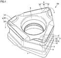
- cutting insert 100 mainly has a first surface 5, a second surface 7, and a side surface 6.
- first surface 5 and second surface 7 has a substantially polygonal (substantially hexagonal) shape having, for example, an acute corner (or a right angle corner) and an obtuse corner alternately.
- Second surface 7 is located opposite to first surface 5.
- Side surface 6 is continuous with both first surface 5 and second surface 7.
- Cutting insert 100 is provided with a through hole 8 opening on first surface 5 and second surface 7.
- a ridge line between first surface 5 and side surface 6 includes a cutting edge 3.
- Cutting edge 3 is provided, for example, at each of three corners on substantially hexagonal first surface 5.
- a ridge line between second surface 7 and side surface 6 includes cutting edge 3.
- Cutting edge 3 is provided, for example, at each of three corners on substantially hexagonal second surface 7.
- First surface 5 mainly has a rake surface 9 and a reference surface 1.
- Rake surface 9 is continuous with cutting edge 3.
- Reference surface 1 is located on a side opposite to cutting edge 3 with respect to rake surface 9.
- Reference surface 1 has a planar shape.
- Reference surface 1 is, for example, a seating surface.
- Reference surface 1 is located between through hole 8 and rake surface 9. For example, the seating surface of cutting insert 100 is brought into contact with a milling cutter body 101, and thus cutting insert 100 is positioned.
- cutting edge 3 mainly has a corner cutting edge 33, a flat drag 13, and a main cutting edge 23.
- Corner cutting edge 33 is located at a nose rounded portion of first surface 5.
- Corner cutting edge 33 has a first end portion C1 and a second end portion C2.
- Second end portion C2 is an end portion located opposite to first end portion C1.
- Flat drag 13 is continuous with first end portion C1 of corner cutting edge 33.
- Main cutting edge 23 is continuous with second end portion C2 of corner cutting edge 33.
- Rake surface 9 has a first rake surface portion 10, a second rake surface portion 20, and a third rake surface portion 30.
- First rake surface portion 10 is continuous with flat drag 13.
- Second rake surface portion 20 is continuous with main cutting edge 23.
- Third rake surface portion 30 is continuous with corner cutting edge 33.
- Third rake surface portion 30 is located between first rake surface portion 10 and second rake surface portion 20.
- first rake surface portion 10 may have a first inclined surface 11 and a first land surface 12.
- First land surface 12 is continuous with flat drag 13.
- First inclined surface 11 is continuous with first land surface 12.
- First inclined surface 11 is located on a side opposite to flat drag 13 with respect to first land surface 12.
- Second rake surface portion 20 may have a second inclined surface 21 and a second land surface 22.
- Second land surface 22 is continuous with main cutting edge 23.
- Second inclined surface 21 is continuous with second land surface 22.
- Second inclined surface 21 is located on a side opposite to main cutting edge 23 with respect to second land surface 22.
- Third rake surface portion 30 may have a third inclined surface 31 and a third land surface 32.
- Third land surface 32 is continuous with corner cutting edge 33.
- Third inclined surface 31 is continuous with third land surface 32.
- Third inclined surface 31 is located on a side opposite to corner cutting edge 33 with respect to third land surface 32.
- first inclined surface 11 is inclined at a first angle ⁇ 1 with respect to a plane P1 parallel to reference surface 1.
- First angle ⁇ 1 is, for example, greater than or equal to 3° and less than or equal to 30°.
- a fourth inclined surface 4 is continuous with first inclined surface 11.
- Reference surface 1 is continuous with fourth inclined surface 4.
- Fourth inclined surface 4 is located between first inclined surface 11 and reference surface 1.
- An inclination angle of fourth inclined surface 4 with respect to reference surface 1 may be greater than an inclination angle of first inclined surface 11 with respect to reference surface 1.
- second inclined surface 21 is inclined at a second angle ⁇ 2 with respect to plane P2 parallel to reference surface 1.
- Second angle ⁇ 2 is greater than first angle ⁇ 1.
- Second angle ⁇ 2 is, for example, greater than or equal to 3° and less than or equal to 30°.
- a fifth inclined surface 25 is continuous with second inclined surface 21.
- Reference surface 1 is continuous with fifth inclined surface 25.
- Fifth inclined surface 25 is located between second inclined surface 21 and reference surface 1.
- Fifth inclined surface 25 is higher as approaching reference surface 1.
- a boundary portion 24 between second inclined surface 21 and fifth inclined surface 25 is lower than reference surface 1 in a direction perpendicular to reference surface 1. In other words, a plane along reference surface 1 intersects second inclined surface 21.
- First angle ⁇ 1 is a positive angle with respect to reference surface 1.
- first angle ⁇ 1 being a positive angle with respect to reference surface 1 means that first inclined surface 11 is inclined with respect to reference surface 1 such that first inclined surface 11 becomes lower as the distance from flat drag 13 increases.
- first angle ⁇ 1 being a positive angle with respect to reference surface 1 means a case where first inclined surface 11 extends to the lower left in a case where cutting insert 100 is disposed such that flat drag 13 faces to the right and reference surface 1 faces upward (see Fig. 4 ).
- first land surface 12 is inclined with respect to reference surface 1 so as to be higher as the distance from flat drag 13 increases.
- An inclination angle of first land surface 12 with respect to reference surface 1 is a negative angle.
- second angle ⁇ 2 is a positive angle with respect to reference surface 1.
- second angle ⁇ 2 being a positive angle with respect to reference surface 1 means that second inclined surface 21 is inclined with respect to reference surface 1 such that second inclined surface 21 becomes lower as the distance from main cutting edge 23 increases.
- second angle ⁇ 2 being a positive angle with respect to reference surface 1 means a case where second inclined surface 21 extends to the lower right in a case where cutting insert 100 is disposed such that main cutting edge 23 faces to the left and reference surface 1 faces upward (see Fig. 5 ).
- second land surface 22 is inclined with respect to reference surface 1 so as to be higher as the distance from main cutting edge 23 increases.
- An inclination angle of second land surface 22 with respect to reference surface 1 is a negative angle.
- side surface 6 has a first side portion 61, a second side portion 62, and a third side portion 63.
- a ridge line between first side portion 61 and first rake surface portion 10 constitutes flat drag 13.
- a ridge line between second side portion 62 and second rake surface portion 20 constitutes main cutting edge 23.
- a ridge line between third side portion 63 and third rake surface portion 30 constitutes corner cutting edge 33.
- first end portion C1 and second end portion C2 of corner cutting edge 33 are higher than reference surface 1.
- First end portion C1 and second end portion C2 being higher than reference surface 1 means that first end portion C1 and second end portion C2 are located higher than reference surface 1 in a case where cutting insert 100 is disposed such that reference surface 1 faces upward.
- Flat drag 13 becomes higher as the distance from first end portion C1 increases, and then becomes lower after flat drag 13 reaches a peak,.
- the midpoint of the distance between a connecting portion 15 between flat drag 13 and another main cutting edge 123 and first end portion C1 in a direction parallel to reference surface 1 is a central portion 14 of flat drag 13.
- a distance W1 from central portion 14 to connecting portion 15 is equal to a distance W2 from central portion 14 to first end portion C1.
- central portion 14 of flat drag 13 may be higher than first end portion C1.
- main cutting edge 23 becomes lower as the distance from second end portion C2 increases.
- main cutting edge 23 extends so as to intersect reference surface 1.
- main cutting edge 23 approaches reference surface 1, intersects reference surface 1, and then separates from reference surface 1 as the distance from second end portion C2 increases.
- Fig. 8 is a cross section passing through second end portion C2 and parallel to flat drag 13.
- a first step portion 2 rising from a third inclined surface 31 of third rake surface portion 30 and continuous with first rake surface portion 10 is provided on rake surface 9.
- First step portion 2 may be defined by a rising surface 40 and first inclined surface 11 continuous with rising surface 40.
- a boundary portion 36 between third inclined surface 31 and rising surface 40 is lower than first inclined surface 11 in direction D4 perpendicular to reference surface 1.
- first inclined surface 11 becomes monotonically higher as the distance from second end portion C2 increases.
- entirety of first rake surface portion 10 may constitute first step portion 2.
- the height of first inclined surface 11 may be substantially constant or part of first inclined surface 11 may be lower than the other part of first inclined surface 11.
- a height H of first step portion 2 in direction D4 perpendicular to reference surface 1 may be, for example, greater than or equal to 0.04 mm and less than or equal to 0.50 mm.
- height H of first step portion 2 is a distance between boundary portion 36 between third inclined surface 31 and rising surface 40 and a boundary portion 41 between rising surface 40 and first inclined surface 11.
- an inclination angle of third inclined surface 31 with respect to reference surface 1 is a positive angle.
- an inclination angle of rising surface 40 with respect to reference surface 1 is a negative angle.
- An inclination angle is zero at boundary portion 36 between third inclined surface 31 and rising surface 40.
- an inclination angle of first inclined surface 11 with respect to reference surface 1 is a negative angle.
- the inclination angle of first inclined surface 11 with respect to reference surface 1 is smaller than inclination angle of rising surface 40 with respect to reference surface 1.
- the inclination angle changes at boundary portion 41 between rising surface 40 and first inclined surface 11.
- a distance L between first step portion 2 and second end portion C2 in the direction parallel to reference surface 1 is, for example, greater than or equal to 0.4 mm and less than or equal to 3.0 mm. Note that more specifically, the distance between first step portion 2 and second end portion C2 is a distance between boundary portion 41 between rising surface 40 and first inclined surface 11 and second end portion C2.
- first step portion 2 may extend toward first end portion C1 along a boundary line between third rake surface portion 30 and reference surface 1 when viewed in the direction perpendicular to reference surface 1.
- An extending direction of first step portion 2 may be substantially parallel to main cutting edge 23.
- First step portion 2 may be continuous with reference surface 1.
- First step portion 2 may be continuous with fourth inclined surface 4.
- first step portion 2 may be defined by rising surface 40, a top surface 42, and a sixth inclined surface 43. Rising surface 40 rises from third inclined surface 31 toward top surface 42. Sixth inclined surface 43 rises from fourth inclined surface 4 toward top surface 42. The first step portion 2 may be a protruding portion rising from third inclined surface 31 and rising from fourth inclined surface 4.
- an inclination angle of sixth inclined surface 43 with respect to reference surface 1 is a positive angle.
- An inclination angle of rising surface 40 with respect to reference surface 1 is a negative angle.
- the cutting insert according to the second embodiment differs from the cutting insert according to the first embodiment mainly in that the cutting insert according to the second embodiment has a second step portion. Regarding the other configuration, the cutting insert according to the second embodiment is almost identical to the cutting insert according to the first embodiment.
- a configuration of the cutting insert according to the second embodiment will be described focusing on the configuration different from that of the first embodiment.
- a second step portion 16 is provided on a second rake surface portion 20.
- second step portion 16 extends in a direction intersecting an extending direction of a main cutting edge 23.
- second step portion 16 extends in a direction substantially perpendicular to the extending direction of main cutting edge 23.
- Second step portion 16 may be continuous with main cutting edge 23 or may be separated from main cutting edge 23.
- a first step portion 2 extends in a direction intersecting an extending direction of a flat drag 13.
- first step portion 2 extends in a direction substantially perpendicular to the extending direction of flat drag 13.
- the second step portion 16 may be continuous with first step portion 2 or may be separated from first step portion 2.
- a side surface 6 includes a first side portion 61 continuous with flat drag 13 and a third side portion 63 continuous with a corner cutting edge 33.
- Flat drag 13 has a first flat drag portion 13a and a second flat drag portion 13b.
- First flat drag portion 13a is closer to corner cutting edge 33.
- Second flat drag portion 13b is continuous with first flat drag portion 13a.
- Second flat drag portion 13b is located on a side opposite to corner cutting edge 33 with respect to first flat drag portion 13a.
- First flat drag portion 13a is positioned between second flat drag portion 13b and corner cutting edge 33.
- an inclination angle ⁇ 3 of first flat drag portion 13a with respect to a straight line 1a parallel to reference surface 1 is greater than an inclination angle ⁇ 4 of second flat drag portion 13b with respect to a straight line 1b parallel to reference surface 1 when viewed in a direction perpendicular to first side portion 61.
- flat drag 13 when viewed in a direction perpendicular to first side portion 61, flat drag 13 has an inflection point where inclination of flat drag 13 changes.
- a boundary portion 13c between first flat drag portion 13a and second flat drag portion 13b becomes the inflection point.
- An inclination angle ⁇ 3 of first flat drag portion 13a with respect to a straight line 1a parallel to reference surface 1 may be, for example, greater than or equal to 10° and less than or equal to 60°, or may be greater than or equal to 15° and less than or equal to 55°.
- the value obtained by subtracting inclination angle ⁇ 4 from inclination angle ⁇ 3 may be, for example, greater than or equal to 5°, or may be greater than or equal to 10°.
- a distance D between a boundary portion 13c between first flat drag portion 13a and second flat drag portion 13b and a lowermost position of corner cutting edge 33 in a direction perpendicular to reference surface 1 is, for example, greater than or equal to 0.04 mm and less than or equal to 0.5 mm.
- side surface 6 includes a second side portion 62 continuous with main cutting edge 23.
- Main cutting edge 23 has a first main cutting edge portion 23a and a second main cutting edge portion 23b.
- First main cutting edge portion 23a is on a corner cutting edge side with respect to second main cutting edge portion 23b.
- Second main cutting edge portion 23b is continuous with first main cutting edge portion 23a.
- Second main cutting edge portion 23b is on a side opposite to corner cutting edge 33 with respect to first main cutting edge portion 23a.
- First main cutting edge portion 23a is positioned between second main cutting edge portion 23b and corner cutting edge 33.
- an inclination angle ⁇ 5 of first main cutting edge portion 23a with respect to a straight line 1c parallel to reference surface 1 is greater than an inclination angle ⁇ 6 of second main cutting edge portion 23b with respect to a straight line 1d parallel to reference surface 1.
- main cutting edge 23 when viewed in the direction perpendicular to second side portion 62, main cutting edge 23 has an inflection point where inclination of main cutting edge 23 changes.
- a boundary portion 23c between first main cutting edge portion 23a and second main cutting edge portion 23b is the inflection point.
- Inclination angle ⁇ 5 of first main cutting edge portion 23a with respect to straight line 1a parallel to reference surface 1 may be, for example, greater than or equal to 10° and less than or equal to 60°, or may be greater than or equal to 15° and less than or equal to 55°.
- second main cutting edge portion 23b extends such that the height in the direction perpendicular to reference surface 1 is lower as the distance from boundary portion 23c between first main cutting edge portion 23a and second main cutting edge portion 23b increases.
- a distance E between boundary portion 23c between first main cutting edge portion 23a and second main cutting edge portion 23b and a lowermost position 23d of main cutting edge 23 in the direction perpendicular to reference surface 1 is greater than or equal to 0.04 mm and less than or equal to 0.5 mm.
- Fig. 15 is a cross section passing through a middle point MP (see Fig. 12 ) between a first end portion C1 and a second end portion C2 in a direction parallel to flat drag 13, the cross section being parallel to main cutting edge 23.
- second rake surface portion 20 has a first area 20a, a second area 20b, and a rising surface 20c.
- First area 20a is continuous with a third rake surface portion 30.
- Second area 20b is located on a side opposite to a third rake surface portion 30 with respect to first area 20a.
- First area 20a is located between second area 20b and third rake surface portion 30.
- Second step portion 16 rising from first area 20a and continuous with second area 20b is provided on second rake surface portion 20.
- Second step portion 16 is defined by a rising surface 20c and second area 20b continuous with rising surface 20c.
- a distance I between second step portion 16 and corner cutting edge 33 in a direction parallel to reference surface 1 is, for example, 1.5 mm.
- distance I between second step portion 16 and corner cutting edge 33 is a distance between a boundary portion 20d between rising surface 20c and second area 20b and corner cutting edge 33.
- Distance I between second step portion 16 and corner cutting edge 33 may be greater than distance L (see Fig. 8 ) between first step portion 2 and second end portion C2.
- first area 20a extends such that the height in a direction D4 perpendicular to reference surface 1 lowers as the distance from corner cutting edge 33 increases.
- Rising surface 20c extends such that the height in direction D4 perpendicular to reference surface 1 becomes higher as the distance from corner cutting edge 33 increases.
- Second area 20b extends such that the height in direction D4 perpendicular to reference surface 1 lowers as the distance from corner cutting edge 33 increases.
- a height F of second step portion 16 in direction D4 perpendicular to reference surface 1 is, for example, greater than or equal to 0.04 mm and less than or equal to 0.5 mm.
- Height F of second step portion 16 is a distance between a lowermost position 37 of second rake surface portion 20 and boundary portion 20d between rising surface 20c and second area 20b in direction D4 perpendicular to reference surface 1.
- An inclination angle ⁇ 7 of rising surface 20c of second step portion 16 with respect to a plane parallel to reference surface 1 is, for example, greater than or equal to 10° and less than or equal to 60°.
- Fig. 16 is a cross section passing through second end portion C2 and parallel to flat drag 13.
- first step portion 2 rising from third rake surface portion 30 and continuous with first rake surface portion 10 is provided on rake surface 9.
- First step portion 2 is defined by rising surface 40 and first rake surface portion 10 continuous with rising surface 40.
- first rake surface portion 10 becomes monotonically higher as the distance from second end portion C2 increases.
- Inclination angle ⁇ 7 (see Fig. 15 ) of rising surface 20c of second step portion 16 with respect to a plane parallel to reference surface 1 may be smaller than an inclination angle ⁇ 8 (see Fig.
- a height G of first step portion 2 in direction D4 perpendicular to reference surface 1 is, for example, greater than or equal to 0.04 mm and less than or equal to 0.5 mm.
- Height G of first step portion 2 is a distance between a lowermost position 38 of third rake surface portion 30 and a boundary portion 41 between rising surface 40 and first rake surface portion 10 in direction D4 perpendicular to reference surface 1.
- Inclination angle ⁇ 8 of rising surface 40 of first step portion 2 with respect to the plane parallel to reference surface 1 is, for example, greater than or equal to 10° and less than or equal to 60°.
- first step portion 2 works so as to prevent chip 102 from being discharged in the vicinity of corner cutting edge 33. Therefore, discharge speed V1 of part of the chip in the vicinity of corner cutting edge 33 is lower than discharge speed V2 of part of the chip in the vicinity of main cutting edge 23. As a result, the discharge direction of chip 102 is a direction D1 including a vector component in the inner circumferential direction of the milling cutter body. Therefore, it is possible to reduce the likelihood that chip 102 will come into contact with (machined) side surface 72 of workpiece 70 after machining.
- cutting insert 100 it is possible to reduce the likelihood that chip 102 will come into contact with an (unmachined) upper surface 73 of workpiece 70 (before machining). As a result, it is possible to reduce the likelihood that a scratch mark will remain on upper surface 73. Further, since it is possible to reduce the likelihood that chip 102 will come into contact with side surface 72, chip 102 is discharged satisfactorily. As a result, it is possible to reduce the likelihood that chip 102 will come into contact with a bottom surface 71 of workpiece 70, that is, a surface machined by the flat drag. As a result, it is possible to reduce the likelihood that a scratch mark will be formed on bottom surface 71 of workpiece 70. Furthermore, it is possible to reduce the likelihood that chip 102 will come into contact with side surface 6 of cutting insert 100. As a result, it is possible to reduce the likelihood that a scratch mark will be formed on side surface 6 of cutting insert 100.
Landscapes
- Engineering & Computer Science (AREA)
- Mechanical Engineering (AREA)
- Milling Processes (AREA)
- Cutting Tools, Boring Holders, And Turrets (AREA)
Claims (13)
- Schneidplatte, die umfasst:eine erste Oberfläche (5);eine zweite Oberfläche (7), die der ersten Oberfläche gegenüberliegt, und eine Seitenfläche (6), die sich sowohl an die erste Oberfläche als auch an die zweite Oberfläche anschließt, wobeieine Spitzenlinie zwischen der ersten Oberfläche und der Seitenfläche eine Schneide (3) enthält,die erste Oberfläche eine sich an die Schneide anschließende Spanfläche (9) und eine Bezugsfläche (1) aufweist, die sich an einer der Schneide in Bezug auf die Spanfläche gegenüberliegenden Seite befindet und eine plane Form hat,die Schneide eine Ecken-Schneide (33), eine flache Schräge (flat drag) (13), die sich an einen ersten Endabschnitt (C1) der Ecken-Schneide anschließt, und eine Haupt-Schneide (23) aufweist, die sich an einen zweiten Endabschnitt (C2) der Ecken-Schneide anschließt, wobei der zweite Endabschnitt dem ersten Endabschnitt gegenüberliegt,die Spanfläche einen ersten Spanflächen-Abschnitt (10), der sich an die flache Schräge anschließt, einen zweiten Spanflächen-Abschnitt (20), der sich an die Haupt-Schneide anschließt, und einen dritten Spanflächen-Abschnitt (30) aufweist, der sich an die Ecken-Schneide anschließt und sich zwischen dem ersten Spanflächen-Abschnitt und dem zweiten Spanflächen-Abschnitt befindet,der erste Spanflächen-Abschnitt eine erste geneigte Fläche (11) aufweist, die in einem ersten Winkel (θ1) in Bezug auf die Bezugsfläche geneigt ist,der zweite Spanflächen-Abschnitt eine zweite geneigte Fläche (21) aufweist, die in einem zweiten Winkel (θ2), der größer ist als der erste Winkel, in Bezug auf die Bezugsfläche geneigt ist,der erste Winkel und der zweite Winkel positive Winkel in Bezug auf die Bezugsfläche sind,der erste Endabschnitt und der zweite Endabschnitt in einer Richtung senkrecht zu der Bezugsfläche höher sind als die Bezugsfläche,undein erster Absatzabschnitt (2), der von dem dritten Spanflächen-Abschnitt ansteigt und sich an den ersten Spanflächen-Abschnitt anschließt, an der Spanfläche vorhanden ist, dadurch gekennzeichnet, dass die Haupt-Schneide (23) sich so erstreckt, dass sie die Bezugsfläche (1), in einer Richtung parallel zur Bezugsfläche gesehen, schneidet.
- Schneidplatte nach Anspruch 1, wobei eine Höhe des ersten Absatzabschnitts in der Richtung senkrecht zu der Bezugsfläche in einem Querschnitt, der durch den zweiten Endabschnitt und parallel zu der flachen Schräge verläuft, 0,04 mm oder mehr und 0,50 mm oder weniger beträgt.
- Schneidplatte nach Anspruch 2, wobei ein Abstand zwischen dem ersten Absatzabschnitt und dem zweiten Endabschnitt in einer Richtung parallel zu der Bezugsfläche in dem Querschnitt 0,4 mm oder mehr und 5,0 mm oder weniger beträgt.
- Schneidplatte nach einem der Ansprüche 1 bis 3, wobei die Gesamtheit des ersten Spanflächen-Abschnitts den ersten Absatzabschnitt bildet.
- Schneidplatte nach einem der Ansprüche 1 bis 4, wobei ein Mittelabschnitt der flachen Schräge in der Richtung senkrecht zu der Bezugsfläche höher ist als der erste Endabschnitt.
- Schneidplatte nach einem der Ansprüche 1 bis 5, wobei der erste Winkel 3° oder größer und 30° oder kleiner ist.
- Schneidplatte nach einem der Ansprüche 1 bis 6, wobei der zweite Winkel 3° oder größer und 30° oder kleiner ist.
- Schneidplatte nach einem der Ansprüche 1 bis 7, wobei die Seitenfläche einen ersten Seitenabschnitt einschließt, der sich an die flache Schräge anschließt, und die flache Schräge einen ersten Abschnitt der flachen Schräge, der näher an der Ecken-Schneide liegt, sowie einen zweiten Abschnitt der flachen Schräge aufweist, der sich an die erste flache Schräge anschließt, und
ein Neigungswinkel des ersten Abschnitts der flachen Schräge in Bezug auf eine gerade Linie parallel zu der Bezugsfläche, in einer Richtung senkrecht zu dem ersten Seitenabschnitt gesehen, größer ist als ein Neigungswinkel des zweiten Abschnitts der flachen Schräge in Bezug auf eine gerade Linie parallel zu der Bezugsfläche. - Schneidplatte nach einem der Ansprüche 1 bis 8, wobei der zweite Spanflächen-Abschnitt einen ersten Bereich, der sich an den dritten Spanflächen-Abschnitt anschließt, und einen zweiten Bereich aufweist, der sich an einer dem dritten Spanflächen-Abschnitt in Bezug auf den ersten Bereich gegenüberliegenden Seite befindet, und
ein zweiter Absatzabschnitt, der von dem ersten Bereich ansteigt und sich an den zweiten Bereich anschließt, an dem zweiten Spanflächen-Abschnitt vorhanden ist. - Schneidplatte nach Anspruch 9, wobei eine Höhe des zweiten Absatzabschnitts in der Richtung senkrecht zu der Bezugsfläche in einem Querschnitt, der durch einen mittleren Punkt zwischen dem ersten Endabschnitt und dem zweiten Endabschnitt in einer Richtung parallel zu der flachen Schräge verläuft, 0,04 mm oder mehr und 0,5 mm oder weniger beträgt, wobei der Querschnitt parallel zu der Haupt-Schneide ist.
- Schneidplatte nach Anspruch 9 oder 10, wobei ein Neigungswinkel einer ansteigenden Fläche des zweiten Absatzabschnitts in Bezug auf die Bezugsfläche 10° oder größer und 60° oder kleiner ist.
- Schneidplatte nach einem der Ansprüche 9 bis 11, wobei ein Neigungswinkel einer ansteigenden Fläche des zweiten Absatzabschnitts in Bezug auf die Bezugsfläche kleiner ist als ein Neigungswinkel einer ansteigenden Fläche des ersten Absatzabschnitts in Bezug auf die Bezugsfläche.
- Schneidplatte nach einem der Ansprüche 1 bis 12, wobei die Seitenfläche einen zweiten Seitenabschnitt aufweist, der sich an die Haupt-Schneide anschließt,
die Haupt-Schneide einen ersten Kantenabschnitt der Haupt-Schneide, der näher an der Ecken-Schneide liegt, sowie einen zweiten Kantenabschnitt der Haupt-Schneide aufweist, der sich an den ersten Kantenabschnitt der Haupt-Schneide anschließt, und
ein Neigungswinkel des ersten Abschnitts der Haupt-Schneide in Bezug auf eine gerade Linie parallel zu der Bezugsfläche, in einer Richtung senkrecht zu dem zweiten Seitenabschnitt gesehen, größer ist als ein Neigungswinkel des zweiten Abschnitts der Haupt-Schneide in Bezug auf eine gerade Linie parallel zu der Bezugsfläche.
Applications Claiming Priority (2)
| Application Number | Priority Date | Filing Date | Title |
|---|---|---|---|
| JP2016202652 | 2016-10-14 | ||
| PCT/JP2016/088912 WO2018070058A1 (ja) | 2016-10-14 | 2016-12-27 | 切削インサート |
Publications (3)
| Publication Number | Publication Date |
|---|---|
| EP3527314A1 EP3527314A1 (de) | 2019-08-21 |
| EP3527314A4 EP3527314A4 (de) | 2020-06-24 |
| EP3527314B1 true EP3527314B1 (de) | 2021-05-26 |
Family
ID=61905469
Family Applications (1)
| Application Number | Title | Priority Date | Filing Date |
|---|---|---|---|
| EP16918958.6A Active EP3527314B1 (de) | 2016-10-14 | 2016-12-27 | Schneideinsatz |
Country Status (6)
| Country | Link |
|---|---|
| US (1) | US10875105B2 (de) |
| EP (1) | EP3527314B1 (de) |
| JP (1) | JP6756082B2 (de) |
| CN (1) | CN109715328B (de) |
| BR (1) | BR112019004787A2 (de) |
| WO (1) | WO2018070058A1 (de) |
Families Citing this family (8)
| Publication number | Priority date | Publication date | Assignee | Title |
|---|---|---|---|---|
| MX2020005396A (es) | 2017-11-27 | 2020-12-07 | Dynatech Systems Inc | Manufactura, ensamblaje y metodo de ensamblaje de remoción de materiales. |
| EP3542936A1 (de) * | 2018-03-22 | 2019-09-25 | AB Sandvik Coromant | Schneideinsatz für ein schulterfräswerkzeug |
| USD940767S1 (en) * | 2020-01-24 | 2022-01-11 | Dynatech Systems, Inc. | Cutter head for grinding machines and the like |
| EP4129546A4 (de) * | 2020-03-26 | 2024-04-24 | MOLDINO Tool Engineering, Ltd. | Schneideeinsatz und schneidwerkzeug mit austauschbarer klingenspitze |
| JP7011689B1 (ja) * | 2020-08-11 | 2022-01-27 | 株式会社タンガロイ | 切削インサート及び回転切削工具 |
| USD1070938S1 (en) * | 2021-10-21 | 2025-04-15 | Sumitomo Electric Hardmetal Corp. | Cutting tool |
| JP2024068002A (ja) * | 2022-11-07 | 2024-05-17 | Ntkカッティングツールズ株式会社 | 切削インサート |
| CN117226158B (zh) * | 2023-11-13 | 2024-03-05 | 赣州澳克泰工具技术有限公司 | 一种切削刀片及其切削刀具 |
Family Cites Families (31)
| Publication number | Priority date | Publication date | Assignee | Title |
|---|---|---|---|---|
| JPH0135777Y2 (de) * | 1985-05-25 | 1989-11-01 | ||
| US4755086A (en) * | 1987-10-23 | 1988-07-05 | Gte Valenite Corporation | Cutting insert |
| SE500719C2 (sv) | 1993-01-27 | 1994-08-15 | Sandvik Ab | Skär med skruvformigt vriden spånyta |
| SE500721C2 (sv) * | 1993-01-27 | 1994-08-15 | Sandvik Ab | Skär med vriden spånyta |
| IL108995A (en) * | 1994-03-16 | 1996-12-05 | Iscar Ltd | Exchangeable cutting insert |
| SE509219C2 (sv) * | 1994-10-21 | 1998-12-21 | Sandvik Ab | Frässkär |
| IL111367A0 (en) * | 1994-10-23 | 1994-12-29 | Iscar Ltd | An exchangeable cutting insert |
| IL113122A0 (en) * | 1995-03-24 | 1995-06-29 | Iscar Ltd | A cutting insert |
| JPH09174323A (ja) * | 1995-12-21 | 1997-07-08 | Mitsubishi Materials Corp | スローアウェイチップ及びスローアウェイ式カッタ |
| US7144205B2 (en) | 2003-05-09 | 2006-12-05 | Kennametal Inc. | Insert retention screw and tool body and insert therewith |
| SE531250C2 (sv) * | 2007-06-05 | 2009-02-03 | Sandvik Intellectual Property | Indexerbart hörnfrässkär |
| SE532742C2 (sv) * | 2008-05-13 | 2010-03-30 | Sandvik Intellectual Property | Frässkär med biegg snedställd i måttlig vinkel |
| KR101097658B1 (ko) * | 2009-05-29 | 2011-12-22 | 대구텍 유한회사 | 절삭 삽입체 |
| EP2495060B1 (de) * | 2009-10-28 | 2018-02-07 | Kyocera Corporation | Schneideeinsatz und schneidewerkzeug sowie herstellungsverfahren für schneidewerkstück damit |
| JP5441615B2 (ja) * | 2009-10-29 | 2014-03-12 | 京セラ株式会社 | 切削インサートおよび切削工具ならびに被削加工物の製造方法 |
| IL203283A (en) * | 2010-01-13 | 2014-02-27 | Iscar Ltd | Cutting put |
| EP2394766A1 (de) * | 2010-06-10 | 2011-12-14 | Lamina Technologies SA | Doppelseitige Wendeschneidplatte und Schneidwerkzeug |
| CN103025462B (zh) * | 2010-08-11 | 2015-03-18 | 京瓷株式会社 | 切削镶刀及切削工具、以及使用该切削工具的切削加工物的制造方法 |
| WO2012147924A1 (ja) * | 2011-04-28 | 2012-11-01 | 京セラ株式会社 | 切削インサートおよび切削工具、並びにそれを用いた切削加工物の製造方法 |
| EP2703108B2 (de) * | 2011-04-28 | 2022-09-21 | Kyocera Corporation | Schneideeinsatz, schneidewerkzeug sowie herstellungsverfahren für schneideprodukte damit |
| CN103619517B (zh) * | 2011-06-30 | 2016-04-06 | 京瓷株式会社 | 切削镶刀及切削工具、以及使用该切削工具的切削加工物的制造方法 |
| US8573905B2 (en) * | 2012-03-22 | 2013-11-05 | Iscar, Ltd. | Triangular cutting insert and cutting tool |
| US8708616B2 (en) * | 2012-07-06 | 2014-04-29 | Iscar, Ltd. | Rotary cutting tool and reversible cutting insert therefor |
| JP6205726B2 (ja) * | 2013-01-15 | 2017-10-04 | 三菱マテリアル株式会社 | 正面フライス用切削インサート及び刃先交換式正面フライス |
| EP3100811B1 (de) * | 2014-01-28 | 2022-09-21 | MOLDINO Tool Engineering, Ltd. | Schneideinsatz und rotierendes schneidwerkzeug |
| AT14072U1 (de) * | 2014-02-04 | 2015-04-15 | Ceratizit Luxembourg S R L | Doppelseitiger Frässchneideinsatz und Fräswerkzeug |
| US10315258B2 (en) * | 2014-02-26 | 2019-06-11 | Tungaloy Corporation | Cutting insert and cutting tool |
| JP5888656B2 (ja) * | 2014-06-02 | 2016-03-22 | 住友電工ハードメタル株式会社 | 切削インサートとフライスカッタ |
| CN106457423B (zh) * | 2014-06-24 | 2018-09-07 | 住友电工硬质合金株式会社 | 切削刀具和刀具本体 |
| US9468983B2 (en) * | 2014-09-22 | 2016-10-18 | Iscar, Ltd. | Rotary cutting tool and reversible cutting insert having variable-width minor relief surfaces therefor |
| US11110526B2 (en) * | 2016-12-27 | 2021-09-07 | Sumitomo Electric Hardmetal Corp. | Cutting insert |
-
2016
- 2016-12-27 EP EP16918958.6A patent/EP3527314B1/de active Active
- 2016-12-27 US US16/333,520 patent/US10875105B2/en active Active
- 2016-12-27 CN CN201680089318.9A patent/CN109715328B/zh active Active
- 2016-12-27 JP JP2018544675A patent/JP6756082B2/ja active Active
- 2016-12-27 WO PCT/JP2016/088912 patent/WO2018070058A1/ja not_active Ceased
- 2016-12-27 BR BR112019004787-5A patent/BR112019004787A2/pt not_active Application Discontinuation
Non-Patent Citations (1)
| Title |
|---|
| None * |
Also Published As
| Publication number | Publication date |
|---|---|
| WO2018070058A1 (ja) | 2018-04-19 |
| JPWO2018070058A1 (ja) | 2019-09-05 |
| EP3527314A1 (de) | 2019-08-21 |
| US10875105B2 (en) | 2020-12-29 |
| BR112019004787A2 (pt) | 2019-06-04 |
| WO2018070058A9 (ja) | 2018-11-08 |
| CN109715328B (zh) | 2020-09-29 |
| JP6756082B2 (ja) | 2020-09-16 |
| US20190255621A1 (en) | 2019-08-22 |
| CN109715328A (zh) | 2019-05-03 |
| EP3527314A4 (de) | 2020-06-24 |
Similar Documents
| Publication | Publication Date | Title |
|---|---|---|
| EP3527314B1 (de) | Schneideinsatz | |
| JP6353941B2 (ja) | 切削インサートおよび切削工具、並びにそれを用いた切削加工物の製造方法 | |
| CN103930228B (zh) | 切削镶刀及切削工具、以及使用该切削工具的切削加工物的制造方法 | |
| EP2703108B1 (de) | Schneideeinsatz, schneidewerkzeug sowie herstellungsverfahren für schneideprodukte damit | |
| EP3150317B1 (de) | Schneideinsatz und fräswerkzeug | |
| JP5525615B2 (ja) | 切削インサートおよび切削工具、並びにそれらを用いた切削加工物の製造方法 | |
| EP2805786B1 (de) | Indizierbarer Schneideinsatz mit Seitenabstütztal, und Fräswerkzeug | |
| EP2727672B1 (de) | Schneideeinsatz, schneidewerkzeug sowie herstellungsverfahren für ein schneideprodukt mit dem schneidewerkzeug | |
| JP7069487B2 (ja) | 切削インサート | |
| WO2011046045A1 (ja) | 切削インサート | |
| JP6957827B2 (ja) | 切削インサート | |
| US10046396B2 (en) | Cutting insert, cutting tool, and method for manufacturing machined product | |
| WO2018042957A1 (ja) | 切削インサート | |
| CN116033988A (zh) | 旋转切削刀具用切削刀片及旋转切削刀具 | |
| JP6648392B1 (ja) | 切削インサート |
Legal Events
| Date | Code | Title | Description |
|---|---|---|---|
| STAA | Information on the status of an ep patent application or granted ep patent |
Free format text: STATUS: THE INTERNATIONAL PUBLICATION HAS BEEN MADE |
|
| PUAI | Public reference made under article 153(3) epc to a published international application that has entered the european phase |
Free format text: ORIGINAL CODE: 0009012 |
|
| STAA | Information on the status of an ep patent application or granted ep patent |
Free format text: STATUS: REQUEST FOR EXAMINATION WAS MADE |
|
| 17P | Request for examination filed |
Effective date: 20190308 |
|
| AK | Designated contracting states |
Kind code of ref document: A1 Designated state(s): AL AT BE BG CH CY CZ DE DK EE ES FI FR GB GR HR HU IE IS IT LI LT LU LV MC MK MT NL NO PL PT RO RS SE SI SK SM TR |
|
| AX | Request for extension of the european patent |
Extension state: BA ME |
|
| DAV | Request for validation of the european patent (deleted) | ||
| DAX | Request for extension of the european patent (deleted) | ||
| A4 | Supplementary search report drawn up and despatched |
Effective date: 20200527 |
|
| RIC1 | Information provided on ipc code assigned before grant |
Ipc: B23C 5/06 20060101ALI20200519BHEP Ipc: B23C 5/20 20060101AFI20200519BHEP |
|
| GRAP | Despatch of communication of intention to grant a patent |
Free format text: ORIGINAL CODE: EPIDOSNIGR1 |
|
| STAA | Information on the status of an ep patent application or granted ep patent |
Free format text: STATUS: GRANT OF PATENT IS INTENDED |
|
| INTG | Intention to grant announced |
Effective date: 20201218 |
|
| GRAS | Grant fee paid |
Free format text: ORIGINAL CODE: EPIDOSNIGR3 |
|
| GRAA | (expected) grant |
Free format text: ORIGINAL CODE: 0009210 |
|
| STAA | Information on the status of an ep patent application or granted ep patent |
Free format text: STATUS: THE PATENT HAS BEEN GRANTED |
|
| AK | Designated contracting states |
Kind code of ref document: B1 Designated state(s): AL AT BE BG CH CY CZ DE DK EE ES FI FR GB GR HR HU IE IS IT LI LT LU LV MC MK MT NL NO PL PT RO RS SE SI SK SM TR |
|
| REG | Reference to a national code |
Ref country code: GB Ref legal event code: FG4D |
|
| REG | Reference to a national code |
Ref country code: CH Ref legal event code: EP |
|
| REG | Reference to a national code |
Ref country code: DE Ref legal event code: R096 Ref document number: 602016058661 Country of ref document: DE |
|
| REG | Reference to a national code |
Ref country code: AT Ref legal event code: REF Ref document number: 1395717 Country of ref document: AT Kind code of ref document: T Effective date: 20210615 |
|
| REG | Reference to a national code |
Ref country code: IE Ref legal event code: FG4D |
|
| REG | Reference to a national code |
Ref country code: LT Ref legal event code: MG9D |
|
| REG | Reference to a national code |
Ref country code: AT Ref legal event code: MK05 Ref document number: 1395717 Country of ref document: AT Kind code of ref document: T Effective date: 20210526 |
|
| PG25 | Lapsed in a contracting state [announced via postgrant information from national office to epo] |
Ref country code: FI Free format text: LAPSE BECAUSE OF FAILURE TO SUBMIT A TRANSLATION OF THE DESCRIPTION OR TO PAY THE FEE WITHIN THE PRESCRIBED TIME-LIMIT Effective date: 20210526 Ref country code: LT Free format text: LAPSE BECAUSE OF FAILURE TO SUBMIT A TRANSLATION OF THE DESCRIPTION OR TO PAY THE FEE WITHIN THE PRESCRIBED TIME-LIMIT Effective date: 20210526 Ref country code: BG Free format text: LAPSE BECAUSE OF FAILURE TO SUBMIT A TRANSLATION OF THE DESCRIPTION OR TO PAY THE FEE WITHIN THE PRESCRIBED TIME-LIMIT Effective date: 20210826 Ref country code: AT Free format text: LAPSE BECAUSE OF FAILURE TO SUBMIT A TRANSLATION OF THE DESCRIPTION OR TO PAY THE FEE WITHIN THE PRESCRIBED TIME-LIMIT Effective date: 20210526 Ref country code: HR Free format text: LAPSE BECAUSE OF FAILURE TO SUBMIT A TRANSLATION OF THE DESCRIPTION OR TO PAY THE FEE WITHIN THE PRESCRIBED TIME-LIMIT Effective date: 20210526 |
|
| REG | Reference to a national code |
Ref country code: NL Ref legal event code: MP Effective date: 20210526 |
|
| PG25 | Lapsed in a contracting state [announced via postgrant information from national office to epo] |
Ref country code: LV Free format text: LAPSE BECAUSE OF FAILURE TO SUBMIT A TRANSLATION OF THE DESCRIPTION OR TO PAY THE FEE WITHIN THE PRESCRIBED TIME-LIMIT Effective date: 20210526 Ref country code: IS Free format text: LAPSE BECAUSE OF FAILURE TO SUBMIT A TRANSLATION OF THE DESCRIPTION OR TO PAY THE FEE WITHIN THE PRESCRIBED TIME-LIMIT Effective date: 20210926 Ref country code: GR Free format text: LAPSE BECAUSE OF FAILURE TO SUBMIT A TRANSLATION OF THE DESCRIPTION OR TO PAY THE FEE WITHIN THE PRESCRIBED TIME-LIMIT Effective date: 20210827 Ref country code: PL Free format text: LAPSE BECAUSE OF FAILURE TO SUBMIT A TRANSLATION OF THE DESCRIPTION OR TO PAY THE FEE WITHIN THE PRESCRIBED TIME-LIMIT Effective date: 20210526 Ref country code: NO Free format text: LAPSE BECAUSE OF FAILURE TO SUBMIT A TRANSLATION OF THE DESCRIPTION OR TO PAY THE FEE WITHIN THE PRESCRIBED TIME-LIMIT Effective date: 20210826 Ref country code: PT Free format text: LAPSE BECAUSE OF FAILURE TO SUBMIT A TRANSLATION OF THE DESCRIPTION OR TO PAY THE FEE WITHIN THE PRESCRIBED TIME-LIMIT Effective date: 20210927 Ref country code: SE Free format text: LAPSE BECAUSE OF FAILURE TO SUBMIT A TRANSLATION OF THE DESCRIPTION OR TO PAY THE FEE WITHIN THE PRESCRIBED TIME-LIMIT Effective date: 20210526 Ref country code: RS Free format text: LAPSE BECAUSE OF FAILURE TO SUBMIT A TRANSLATION OF THE DESCRIPTION OR TO PAY THE FEE WITHIN THE PRESCRIBED TIME-LIMIT Effective date: 20210526 |
|
| PG25 | Lapsed in a contracting state [announced via postgrant information from national office to epo] |
Ref country code: NL Free format text: LAPSE BECAUSE OF FAILURE TO SUBMIT A TRANSLATION OF THE DESCRIPTION OR TO PAY THE FEE WITHIN THE PRESCRIBED TIME-LIMIT Effective date: 20210526 |
|
| PG25 | Lapsed in a contracting state [announced via postgrant information from national office to epo] |
Ref country code: EE Free format text: LAPSE BECAUSE OF FAILURE TO SUBMIT A TRANSLATION OF THE DESCRIPTION OR TO PAY THE FEE WITHIN THE PRESCRIBED TIME-LIMIT Effective date: 20210526 Ref country code: DK Free format text: LAPSE BECAUSE OF FAILURE TO SUBMIT A TRANSLATION OF THE DESCRIPTION OR TO PAY THE FEE WITHIN THE PRESCRIBED TIME-LIMIT Effective date: 20210526 Ref country code: CZ Free format text: LAPSE BECAUSE OF FAILURE TO SUBMIT A TRANSLATION OF THE DESCRIPTION OR TO PAY THE FEE WITHIN THE PRESCRIBED TIME-LIMIT Effective date: 20210526 Ref country code: ES Free format text: LAPSE BECAUSE OF FAILURE TO SUBMIT A TRANSLATION OF THE DESCRIPTION OR TO PAY THE FEE WITHIN THE PRESCRIBED TIME-LIMIT Effective date: 20210526 Ref country code: RO Free format text: LAPSE BECAUSE OF FAILURE TO SUBMIT A TRANSLATION OF THE DESCRIPTION OR TO PAY THE FEE WITHIN THE PRESCRIBED TIME-LIMIT Effective date: 20210526 Ref country code: SK Free format text: LAPSE BECAUSE OF FAILURE TO SUBMIT A TRANSLATION OF THE DESCRIPTION OR TO PAY THE FEE WITHIN THE PRESCRIBED TIME-LIMIT Effective date: 20210526 Ref country code: SM Free format text: LAPSE BECAUSE OF FAILURE TO SUBMIT A TRANSLATION OF THE DESCRIPTION OR TO PAY THE FEE WITHIN THE PRESCRIBED TIME-LIMIT Effective date: 20210526 |
|
| REG | Reference to a national code |
Ref country code: DE Ref legal event code: R097 Ref document number: 602016058661 Country of ref document: DE |
|
| PLBE | No opposition filed within time limit |
Free format text: ORIGINAL CODE: 0009261 |
|
| STAA | Information on the status of an ep patent application or granted ep patent |
Free format text: STATUS: NO OPPOSITION FILED WITHIN TIME LIMIT |
|
| 26N | No opposition filed |
Effective date: 20220301 |
|
| PG25 | Lapsed in a contracting state [announced via postgrant information from national office to epo] |
Ref country code: IS Free format text: LAPSE BECAUSE OF FAILURE TO SUBMIT A TRANSLATION OF THE DESCRIPTION OR TO PAY THE FEE WITHIN THE PRESCRIBED TIME-LIMIT Effective date: 20210926 Ref country code: AL Free format text: LAPSE BECAUSE OF FAILURE TO SUBMIT A TRANSLATION OF THE DESCRIPTION OR TO PAY THE FEE WITHIN THE PRESCRIBED TIME-LIMIT Effective date: 20210526 |
|
| PG25 | Lapsed in a contracting state [announced via postgrant information from national office to epo] |
Ref country code: MC Free format text: LAPSE BECAUSE OF FAILURE TO SUBMIT A TRANSLATION OF THE DESCRIPTION OR TO PAY THE FEE WITHIN THE PRESCRIBED TIME-LIMIT Effective date: 20210526 Ref country code: IT Free format text: LAPSE BECAUSE OF FAILURE TO SUBMIT A TRANSLATION OF THE DESCRIPTION OR TO PAY THE FEE WITHIN THE PRESCRIBED TIME-LIMIT Effective date: 20210526 |
|
| REG | Reference to a national code |
Ref country code: CH Ref legal event code: PL |
|
| GBPC | Gb: european patent ceased through non-payment of renewal fee |
Effective date: 20211227 |
|
| REG | Reference to a national code |
Ref country code: BE Ref legal event code: MM Effective date: 20211231 |
|
| PG25 | Lapsed in a contracting state [announced via postgrant information from national office to epo] |
Ref country code: LU Free format text: LAPSE BECAUSE OF NON-PAYMENT OF DUE FEES Effective date: 20211227 Ref country code: IE Free format text: LAPSE BECAUSE OF NON-PAYMENT OF DUE FEES Effective date: 20211227 Ref country code: GB Free format text: LAPSE BECAUSE OF NON-PAYMENT OF DUE FEES Effective date: 20211227 |
|
| PG25 | Lapsed in a contracting state [announced via postgrant information from national office to epo] |
Ref country code: FR Free format text: LAPSE BECAUSE OF NON-PAYMENT OF DUE FEES Effective date: 20211231 Ref country code: BE Free format text: LAPSE BECAUSE OF NON-PAYMENT OF DUE FEES Effective date: 20211231 |
|
| PG25 | Lapsed in a contracting state [announced via postgrant information from national office to epo] |
Ref country code: LI Free format text: LAPSE BECAUSE OF NON-PAYMENT OF DUE FEES Effective date: 20211231 Ref country code: CH Free format text: LAPSE BECAUSE OF NON-PAYMENT OF DUE FEES Effective date: 20211231 |
|
| P01 | Opt-out of the competence of the unified patent court (upc) registered |
Effective date: 20230515 |
|
| PG25 | Lapsed in a contracting state [announced via postgrant information from national office to epo] |
Ref country code: CY Free format text: LAPSE BECAUSE OF FAILURE TO SUBMIT A TRANSLATION OF THE DESCRIPTION OR TO PAY THE FEE WITHIN THE PRESCRIBED TIME-LIMIT Effective date: 20210526 |
|
| PG25 | Lapsed in a contracting state [announced via postgrant information from national office to epo] |
Ref country code: HU Free format text: LAPSE BECAUSE OF FAILURE TO SUBMIT A TRANSLATION OF THE DESCRIPTION OR TO PAY THE FEE WITHIN THE PRESCRIBED TIME-LIMIT; INVALID AB INITIO Effective date: 20161227 |
|
| PG25 | Lapsed in a contracting state [announced via postgrant information from national office to epo] |
Ref country code: MK Free format text: LAPSE BECAUSE OF FAILURE TO SUBMIT A TRANSLATION OF THE DESCRIPTION OR TO PAY THE FEE WITHIN THE PRESCRIBED TIME-LIMIT Effective date: 20210526 |
|
| PG25 | Lapsed in a contracting state [announced via postgrant information from national office to epo] |
Ref country code: TR Free format text: LAPSE BECAUSE OF FAILURE TO SUBMIT A TRANSLATION OF THE DESCRIPTION OR TO PAY THE FEE WITHIN THE PRESCRIBED TIME-LIMIT Effective date: 20210526 |
|
| PG25 | Lapsed in a contracting state [announced via postgrant information from national office to epo] |
Ref country code: MT Free format text: LAPSE BECAUSE OF FAILURE TO SUBMIT A TRANSLATION OF THE DESCRIPTION OR TO PAY THE FEE WITHIN THE PRESCRIBED TIME-LIMIT Effective date: 20210526 |
|
| PGFP | Annual fee paid to national office [announced via postgrant information from national office to epo] |
Ref country code: DE Payment date: 20251104 Year of fee payment: 10 |