EP3527331B1 - Poignée d'un dispositif brûleur - Google Patents
Poignée d'un dispositif brûleur Download PDFInfo
- Publication number
- EP3527331B1 EP3527331B1 EP18214343.8A EP18214343A EP3527331B1 EP 3527331 B1 EP3527331 B1 EP 3527331B1 EP 18214343 A EP18214343 A EP 18214343A EP 3527331 B1 EP3527331 B1 EP 3527331B1
- Authority
- EP
- European Patent Office
- Prior art keywords
- handle
- burner
- connection
- gripping
- hand
- Prior art date
- Legal status (The legal status is an assumption and is not a legal conclusion. Google has not performed a legal analysis and makes no representation as to the accuracy of the status listed.)
- Active
Links
Images
Classifications
-
- B—PERFORMING OPERATIONS; TRANSPORTING
- B25—HAND TOOLS; PORTABLE POWER-DRIVEN TOOLS; MANIPULATORS
- B25G—HANDLES FOR HAND IMPLEMENTS
- B25G1/00—Handle constructions
- B25G1/10—Handle constructions characterised by material or shape
- B25G1/102—Handle constructions characterised by material or shape the shape being specially adapted to facilitate handling or improve grip
-
- F—MECHANICAL ENGINEERING; LIGHTING; HEATING; WEAPONS; BLASTING
- F23—COMBUSTION APPARATUS; COMBUSTION PROCESSES
- F23D—BURNERS
- F23D14/00—Burners for combustion of a gas, e.g. of a gas stored under pressure as a liquid
- F23D14/38—Torches, e.g. for brazing or heating
-
- F—MECHANICAL ENGINEERING; LIGHTING; HEATING; WEAPONS; BLASTING
- F23—COMBUSTION APPARATUS; COMBUSTION PROCESSES
- F23D—BURNERS
- F23D14/00—Burners for combustion of a gas, e.g. of a gas stored under pressure as a liquid
- F23D14/46—Details
- F23D14/465—Details for torches
Definitions
- the invention relates to a handle of a burner device.
- the invention also relates to a burner device comprising such a handle.
- Burner devices are known from the prior art, which are required, for example, for applying bitumen welding sheets to roofs of buildings. Such burner devices have a burner which is connected via a burner tube to a handle on which the burner device can be held by an operator.
- a handle for a burner device according to the preamble of claim 1 is from EP 0 090 080 A1 known. Due to the burner tube, the burner has a long lever arm to the handle, so that high torques act on the handle. These must be absorbed and compensated by the operator, which leads to unfavorable postures. Especially when the burner device is used for a longer period of time, as is the case, for example, with larger roof areas, the conventional handle leads to less ergonomic handling of the burner device.
- Grips are also from the US 2007/0204435 A1 known.
- a handle piece of a burner device comprising a first connection and a second connection as well as a hand element.
- the first connection and the second connection each serve to connect to either a burner or a fuel gas supply.
- a connection to a fuel gas supply can be connected to the first connection or to the second connection, while the burner can be connected to the respective other connection.
- a connecting tube is attached between the first connection and the second connection, the hand element being arranged on the connecting tube.
- the hand element preferably extends at least partially around the connecting tube.
- fuel gas can be passed through the hand element in that the fuel gas is transmitted through the connecting pipe from the first connection to the second connection or vice versa.
- the hand element has a gripping area provided for grasping around by an operator's hand on.
- the hand element has a contact area provided for contact with a forearm of the operator.
- the term forearm includes in particular the wrist.
- the contact area has a greater radial extent away from the connecting pipe in relation to the gripping area, at least in a partial area.
- the contact area can thus be optimally applied to a forearm of the operator.
- the contact area can be placed on the forearm of that arm whose hand grasps the gripping area. This means that leverage forces that result from a torch connected to the handle can be diverted into the forearm via the contact area.
- the gripping area and the contact area are formed in one piece. This enables simple and inexpensive manufacture of the trading element. At the same time, the handle is made compact.
- the gripping area is hollow-cylindrical and the contact area is flat.
- the hollow cylindrical shape comprises in particular an essentially oval cross section. It is preferably provided that the gripping area surrounds the connecting pipe in the circumferential direction, while the contact area is only present on a partial area of the circumference of the connecting pipe. In particular, the contact area extends essentially tangentially to the connecting pipe. It is thus advantageously achieved that the gripping area is designed for gripping with one hand and the contact area for resting on a forearm.
- the contact area is advantageously arranged at least partially on a side of the first connection or the second connection opposite the connecting pipe.
- the contact area is not arranged radially outside and at the level of the connecting pipe. Rather, the contact area extends beyond the first connection or the second connection.
- This makes it possible, in particular, to achieve an optimal balance of a burner device provided with the handle. This creates a fulcrum to which the lever arms on the one hand of the burner and on the other hand of the contact area are determined.
- This pivot point is in particular the area where a hand grips the gripping area. Because the contact area protrudes beyond the first connection or the second connection, a maximum distance between the contact area and the pivot point is maximized.
- optimal contact with the forearm is guaranteed, and on the other hand, low forces are transmitted to the forearm.
- a valve device is preferably arranged between the connecting pipe and the first connection or the second connection.
- the valve device is used in particular to set a flow rate of fuel gas, as a result of which an output power of the burner device can be set.
- the valve device is arranged in particular adjacent to the hand element, in particular to the gripping area.
- the valve device is preferably arranged between the first connection or the second connection and the hand element.
- the directional information relates in particular to an axial direction of the connecting pipe. It is preferably provided that the valve device is arranged directly on the first connection or the second connection, the connecting pipe opening into the valve device.
- valve device and the contact area are particularly advantageously arranged on opposite sides of the gripping area.
- an axial direction of the connecting pipe is to be taken as a basis here.
- the gripping area thus preferably extends from the valve body to the first connection or the second connection. This results in a simple structure.
- valve device and the contact area are arranged on the same side of the gripping area. This leads in particular to an additional improvement in ergonomics.
- a pivot point is defined from which lever arms extend to the burner and to the contact area. Since the valve device is located on the side of the abutment area, a weight of the valve device acts as a counterweight to the weight of the burner. Thus, a force that the abutment area exerts on the operator's forearm is reduced.
- the valve device particularly preferably comprises a valve lever.
- the valve lever is used for the simple and quick setting of an output power of a burner connected to the handle, in that a flow rate of the fuel gas can be easily and quickly adjusted.
- the valve lever extends as far as the gripping area so that it can be easily reached by the operator.
- the valve lever thus extends essentially parallel to the connecting pipe.
- the valve lever and the contact area are advantageously arranged on different sides of the connecting pipe. This relates in particular to a radial direction of the connecting pipe. It is thus provided that the handle piece has an upper side and a lower side after being tied to a burner. If the handle is correctly aligned, ie if the top is at the top and the bottom is at the bottom, the burner in particular is pointing downwards. In such an orientation it is preferably provided that the valve arm is below and the contact area above the Connection pipe is arranged.
- the contact area and valve lever are ergonomically arranged on the handle.
- the contact area preferably corresponds to a maximum of 60%, preferably a maximum of 50%, particularly preferably a maximum of 40%, of a total length of the trading element along the connecting pipe. It is provided that the hand element has an overall length which is measured along the connecting tube. This means that the total length is made up of a length of the gripping area and a length of the contact area, which in turn are each measured along the connecting pipe.
- the described preferred relative dimensions make it possible, on the one hand, to achieve optimum gripping of the gripping area, and, on the other hand, to achieve optimum contact between the contact area and a forearm.
- the hand element is preferably made from an impact-resistant plastic.
- the one-piece design of the gripping area and the contact area can be implemented easily and with little effort.
- a dimension of the trading element can be produced easily and with little effort, adapted to a desired specification. Due to the impact resistance of the plastic from which the hand element is made, the handle is very robust and insensitive to external influences.
- the invention also relates to a burner device.
- the burner device comprises a handle as previously described.
- a burner tube is attached to the first connection or to the second connection of the handle.
- a burner is in turn coupled to the burner tube.
- the burner device can thus be picked up by an operator on the handle. Due to the handle, in particular the contact area, the burner device can be ergonomically held by the operator even with long burner tubes and / or heavy burners.
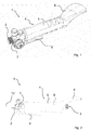
- FIGs 1 and 2 show schematically a handle 1 of a burner device 10 (cf. Fig. 4 ) according to a first embodiment.
- Figure 1 shows a perspective view while Figure 2 shows a side view.
- Figure 2 a part of a burner tube 12, which connects the handle 1 to a burner 11, is also shown.
- the handle 1 has a first connection 2 and a second connection 3. It is provided that the burner 11 can be connected to the first connection 2, in particular via the burner tube 12, while a fuel gas supply can be connected via the second connection 3.
- a connecting pipe 9 is arranged between the first connection 2 and the second connection 3.
- a valve device 7 is attached between the first connection 2 and the second connection 3. It is provided that the valve device 7 is attached directly to the first connection 2.
- the connecting pipe 9 extends from the second connection 3 to the valve device 7.
- the valve device 7 allows a flow rate of the fuel gas from the fuel gas supply to the burner 11, i.e. from the second connection 3 to the first connection 2, to be regulated.
- the connecting pipe 9 is at least partially surrounded by a hand element 4.
- the hand element 4 represents an interface between the handle 1 and an operator, at which the operator can pick up and hold the handle 1.
- the hand element 4 has a gripping area 5 which is designed in the shape of a hollow cylinder and which surrounds the connecting tube 9.
- the hollow cylindrical shape has an essentially oval cross section.
- the gripping area 5 is provided for gripping around with one hand of the operator.
- the hand element 4 has a contact area 6.
- the contact area 6 is intended to rest against a forearm of the operator.
- the contact area 6 can be placed on the forearm of that arm whose hand grips the gripping area 5.
- the contact area 6 has a maximum radial distance from the connecting tube 9, which is greater than a maximum radial distance from the gripping area 5 to the connecting tube 9. In this way, the contact area 6 has a greater radial extent than the gripping area 5, so that the hand element 4 enables optimal gripping by the hand as well as optimal placement on the forearm.
- the handle 1 is ergonomically designed and allows a high level of ease of use.
- the contact area 6 is formed in one piece with the gripping area 5.
- the hand element 4 is made simple and inexpensive and compact.
- the compact design of the trading element 4 enables easy handling of the handle 1 and thus of the burner device 10.
- the hand element 4 is advantageously made of an impact-resistant plastic, so that the handle 1 is resistant to external influences.
- the contact area 6 is flat. Thus, the contact area 6 does not run around the connecting pipe 9 like the gripping area 5, but is arranged essentially tangentially to the connecting pipe 9. The shape of the contact area 6 makes it ideal for resting on the forearm. At the same time, the contact area 6 protects the second connection 3 from the forearm, so that the risk of damage to the handle 1, in particular the second connection 3 or a hose connected to the second connection 3, is minimized.
- the gripping area 5 is in particular attached completely between the first connection 2 and the second connection 3.
- the contact area 6, on the other hand, extends beyond the second connection 3, so that the contact area 6 is at least partially arranged on a side of the second connection 3 opposite the connecting pipe 9. This ensures that the handle 1 can be handled in an optimized manner.
- a pivot point is created at the gripping area 5.
- a torque acts around this pivot point, which is generated by the dead weight of the burner 11 and the burner tube 12 acting as a lever arm. If the contact area 6 is in contact with the operator's forearm, this torque can be compensated for by the contact force of the contact area 6 on the forearm and the distance between the pivot point and the contact area, which acts as a lever arm. The operator can thus handle the handle 1 ergonomically, with holding forces for the operator being minimized.
- the contact area 6 has a length that corresponds to a maximum of 60%, preferably a maximum of 50%, particularly preferably a maximum of 40%, of a total length of the trading element 4 along the connecting tube 9.
- a maximum of 60% preferably a maximum of 50%, particularly preferably a maximum of 40%
- an optimal size distribution of the trading element 4 is achieved, on the one hand to grip the hand element 4 and on the other hand to be able to place it on the forearm.
- the valve device 7 has a valve lever 8.
- the valve lever 8 is used to set a flow rate of fuel gas quickly and easily in order to adapt the output power of the burner 11.
- the valve lever 8 extends from the valve device 7 essentially along the connecting pipe 9 to the gripping area 5. It is still it is provided that the valve lever 8 and the contact area 6 are located on radially opposite sides of the connecting pipe 9. This enables the operator to reach the valve lever 8 easily and ergonomically.
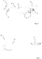
- FIG. 3 shows schematically a handle 1 according to a second embodiment of the invention.
- the only difference to the first exemplary embodiment is the position of the valve device 7.
- the valve device 7 is arranged directly on the second connection 3, so that the connecting pipe 9 runs between the first connection 2 and the valve device 7. This means that the contact area 6 and the valve device 7 are arranged on the same side of the gripping area 5 in a direction that is axial with respect to the connecting pipe 9.
- a pivot point can be found on the gripping area 5, from which the lever arms extend to the burner 11 and the contact area 6. Due to the arrangement of the valve device 7, it is located on a side of the pivot point opposite the burner 11. The valve device 7 thus acts as a counterweight to the burner 11, as a result of which a force which is transmitted to the operator's forearm via the contact surface 6 is reduced.
- FIG 4 shows schematically a burner device 10 according to an embodiment of the invention.
- the handle 1 is used according to the second embodiment of the invention.
- the handle 1 according to the first exemplary embodiment of the invention can also be used.
- the first connection 2 of the handle 1 is coupled to a burner tube 12, a burner 11 being connected to the burner tube 12.
- fuel gas can be transferred from the second connection 3 via the connecting pipe 9, the valve device 7 and the first connection 2 to the burner tube 12 and from there to the burner 11.
- air is mixed in and the fuel gas is burned at the burner 11.
- an output power of the burner 11 can be adjusted.
- the contact area 6 can be applied to a forearm of an operator when using the burner device 10, a torque generated by the burner tube 12 and the burner 11 is absorbed by the forearm.
- the operator can hold the burner device 10 ergonomically and use it fatigue-free even for longer periods of use.
Landscapes
- Engineering & Computer Science (AREA)
- Mechanical Engineering (AREA)
- Chemical & Material Sciences (AREA)
- Combustion & Propulsion (AREA)
- General Engineering & Computer Science (AREA)
- Feeding And Controlling Fuel (AREA)
Claims (9)
- Poignée (1) d'un dispositif brûleur (10) comprenant- un premier raccord (2) et un second raccord (3), respectivement pour la liaison avec un brûleur (11) ou une amenée de gaz de combustion,- un tube de liaison (9) monté entre le premier raccord (2) et le second raccord (3), et- un élément manuel (4) avec une zone de préhension (5) en forme de cylindre creux prévue pour être entourée par une main d'un utilisateur,- dans laquelle l'élément manuel (4) s'étend au moins partiellement autour du tube de liaison (9),caractérisée en ce- que l'élément manuel (4) présente une zone d'appui (6) réalisée à plat, prévue pour l'appui contre un avant-bras de l'utilisateur,- que la zone d'appui (6) présente par rapport à la zone de préhension (5) au moins au niveau d'une zone partielle une étendue radiale supérieure loin du tube de liaison (9), et- que la zone de préhension (5) et la zone d'appui (6) sont réalisées d'un seul tenant.
- Poignée (1) selon l'une des revendications précédentes, caractérisée en ce que la zone d'appui (6) est agencée au moins partiellement sur un côté opposé au tube de liaison du premier raccord (2) ou du second raccord (3).
- Poignée (1) selon l'une des revendications précédentes, caractérisée en ce qu'un dispositif de soupape (7) est agencé entre le tube de liaison (9) et le premier raccord (2) ou le second raccord (3), lequel est agencé en particulier de manière contigüe à la zone de préhension (5).
- Poignée (1) selon la revendication 3, caractérisée en ce que le dispositif de soupape (7) et la zone d'appui (6) sont agencés au niveau de côtés opposés de la zone de préhension (5).
- Poignée (1) selon la revendication 3, caractérisée en ce que le dispositif de soupape (7) et la zone d'appui (6) sont agencés sur un même côté de la zone de préhension (5).
- Poignée (1) selon l'une des revendications 3 à 5, caractérisée en ce que le dispositif de soupape (7) comporte un levier de soupape (8) qui s'étend vers la zone de préhension (5), dans laquelle le levier de soupape (8) et la zone d'appui (6) sont agencés sur différents côtés du tube de liaison (9).
- Poignée (1) selon l'une des revendications précédentes, caractérisée en ce que la zone d'appui (6) présente une longueur qui correspond au maximum à 60 %, de préférence au maximum à 50 %, de manière particulièrement préférée au maximum à 40 %, d'une longueur entière de l'élément manuel (4) le long du tube de liaison (9).
- Poignée (1) selon l'une des revendications précédentes, caractérisée en ce que l'élément manuel (4) est fabriqué en une matière plastique résistante aux chocs.
- Dispositif brûleur (10) comprenant une poignée (1) selon l'une des revendications précédentes, un tube de brûleur (12) et un brûleur (11) couplé au tube de brûleur (12), dans lequel le tube de brûleur (12) est relié au premier raccord (2) ou au second raccord (3) de la poignée (1).
Applications Claiming Priority (1)
| Application Number | Priority Date | Filing Date | Title |
|---|---|---|---|
| DE102018202500.2A DE102018202500A1 (de) | 2018-02-19 | 2018-02-19 | Griffstück einer Brennervorrichtung |
Publications (2)
| Publication Number | Publication Date |
|---|---|
| EP3527331A1 EP3527331A1 (fr) | 2019-08-21 |
| EP3527331B1 true EP3527331B1 (fr) | 2021-03-17 |
Family
ID=64755148
Family Applications (1)
| Application Number | Title | Priority Date | Filing Date |
|---|---|---|---|
| EP18214343.8A Active EP3527331B1 (fr) | 2018-02-19 | 2018-12-20 | Poignée d'un dispositif brûleur |
Country Status (2)
| Country | Link |
|---|---|
| EP (1) | EP3527331B1 (fr) |
| DE (1) | DE102018202500A1 (fr) |
Family Cites Families (5)
| Publication number | Priority date | Publication date | Assignee | Title |
|---|---|---|---|---|
| FR1343579A (fr) * | 1962-09-04 | 1963-11-22 | Harris Calorific Co | Chalumeau à allumoir |
| DE2916875A1 (de) * | 1979-04-26 | 1980-11-06 | Lorch & Co Kg J | Zuendflammenbrenner, insbesondere fuer baustellen |
| DE8208424U1 (de) * | 1982-03-25 | 1982-08-19 | Grün, Helmut, 5900 Siegen | Brennergriff mit ventileinrichtung |
| US5313735A (en) * | 1992-03-02 | 1994-05-24 | Latouche Desmond J | Rotatable handle extension for fishing rods and the like |
| US20070204435A1 (en) * | 2005-09-29 | 2007-09-06 | Pangborn Dominic J | Ergonomic handle |
-
2018
- 2018-02-19 DE DE102018202500.2A patent/DE102018202500A1/de not_active Withdrawn
- 2018-12-20 EP EP18214343.8A patent/EP3527331B1/fr active Active
Non-Patent Citations (1)
| Title |
|---|
| None * |
Also Published As
| Publication number | Publication date |
|---|---|
| EP3527331A1 (fr) | 2019-08-21 |
| DE102018202500A1 (de) | 2019-08-22 |
Similar Documents
| Publication | Publication Date | Title |
|---|---|---|
| DE102009027570A1 (de) | Vorrichtung zum Positionieren und Befestigen einer Einrichtung, insbesondere eines Handgriffs an einem Elektrowerkzeug | |
| DE2217490B2 (de) | Halterung einer schwimmend gelagerten mutter an einem werkstueck | |
| EP1261442B1 (fr) | Dispositif pour debosseler la tole | |
| EP3784439A1 (fr) | Pince | |
| EP2168865A2 (fr) | Embrayage à chaîne pour un vélo | |
| DE202013005119U1 (de) | Arbeitsgerät | |
| EP3527331B1 (fr) | Poignée d'un dispositif brûleur | |
| DE3504100C2 (de) | Druckmittelbetätigter Lochgreifer | |
| EP0645546A1 (fr) | Dispositif de fixation | |
| DE102013106273A1 (de) | Vorrichtung zum Halten einer Stütze an einem Trägergestell | |
| DE2801828B2 (de) | Lösbarer Klemmhalter mit einem Handgriff zum Aufsetzen auf den Spindelhals einer Handbohrmaschine, eines Bohrhammers o.dgl | |
| DE10231724B4 (de) | Halteschelle | |
| DE9110718U1 (de) | Blindniet-Handzange | |
| DE2641385C3 (de) | Vorrichtung zur Befestigung eines ein Stielloch aufweisenden Werkzeugs | |
| DE202008005705U1 (de) | Drehmomentschlüssel mit digitaler Anzeige | |
| DE102021204712A1 (de) | Nagelzieher und Verfahren zum Ziehen eines Schienennagels eines Gleises | |
| DE9216760U1 (de) | Markiergerät zum Anbringen von Markierungen an Rohrmänteln | |
| EP0648002B1 (fr) | Collier de serrage à clou | |
| DE3631995A1 (de) | Vorrichtung fuer die schraubbetaetigung von panzergewinde-verschraubungen | |
| DE102014105012A1 (de) | Universalzange | |
| DE102024132809A1 (de) | Tragevorrichtung zum manuellen Tragen von Behältern mit nach außen hervorragendem Kragen, insbesondere Formen für Beton-Prüfkörper | |
| DE202010005471U1 (de) | Handwerkzeug | |
| DE202009006026U1 (de) | Anschlagkörper für Betonschalungen | |
| DD208578A1 (de) | Greifer fuer manipulatoren | |
| DE4335884C2 (de) | Unkrautzange |
Legal Events
| Date | Code | Title | Description |
|---|---|---|---|
| PUAI | Public reference made under article 153(3) epc to a published international application that has entered the european phase |
Free format text: ORIGINAL CODE: 0009012 |
|
| STAA | Information on the status of an ep patent application or granted ep patent |
Free format text: STATUS: THE APPLICATION HAS BEEN PUBLISHED |
|
| AK | Designated contracting states |
Kind code of ref document: A1 Designated state(s): AL AT BE BG CH CY CZ DE DK EE ES FI FR GB GR HR HU IE IS IT LI LT LU LV MC MK MT NL NO PL PT RO RS SE SI SK SM TR |
|
| AX | Request for extension of the european patent |
Extension state: BA ME |
|
| STAA | Information on the status of an ep patent application or granted ep patent |
Free format text: STATUS: REQUEST FOR EXAMINATION WAS MADE |
|
| 17P | Request for examination filed |
Effective date: 20200220 |
|
| RBV | Designated contracting states (corrected) |
Designated state(s): AL AT BE BG CH CY CZ DE DK EE ES FI FR GB GR HR HU IE IS IT LI LT LU LV MC MK MT NL NO PL PT RO RS SE SI SK SM TR |
|
| GRAP | Despatch of communication of intention to grant a patent |
Free format text: ORIGINAL CODE: EPIDOSNIGR1 |
|
| STAA | Information on the status of an ep patent application or granted ep patent |
Free format text: STATUS: GRANT OF PATENT IS INTENDED |
|
| RIC1 | Information provided on ipc code assigned before grant |
Ipc: F23D 14/38 20060101ALI20201030BHEP Ipc: F23D 14/46 20060101ALI20201030BHEP Ipc: B25G 1/10 20060101AFI20201030BHEP |
|
| INTG | Intention to grant announced |
Effective date: 20201208 |
|
| GRAS | Grant fee paid |
Free format text: ORIGINAL CODE: EPIDOSNIGR3 |
|
| GRAA | (expected) grant |
Free format text: ORIGINAL CODE: 0009210 |
|
| STAA | Information on the status of an ep patent application or granted ep patent |
Free format text: STATUS: THE PATENT HAS BEEN GRANTED |
|
| AK | Designated contracting states |
Kind code of ref document: B1 Designated state(s): AL AT BE BG CH CY CZ DE DK EE ES FI FR GB GR HR HU IE IS IT LI LT LU LV MC MK MT NL NO PL PT RO RS SE SI SK SM TR |
|
| REG | Reference to a national code |
Ref country code: GB Ref legal event code: FG4D Free format text: NOT ENGLISH |
|
| REG | Reference to a national code |
Ref country code: CH Ref legal event code: EP Ref country code: CH Ref legal event code: NV Representative=s name: VALIPAT S.A. C/O BOVARD SA NEUCHATEL, CH |
|
| REG | Reference to a national code |
Ref country code: DE Ref legal event code: R096 Ref document number: 502018004351 Country of ref document: DE |
|
| REG | Reference to a national code |
Ref country code: IE Ref legal event code: FG4D Free format text: LANGUAGE OF EP DOCUMENT: GERMAN |
|
| REG | Reference to a national code |
Ref country code: AT Ref legal event code: REF Ref document number: 1371808 Country of ref document: AT Kind code of ref document: T Effective date: 20210415 |
|
| REG | Reference to a national code |
Ref country code: NL Ref legal event code: FP |
|
| REG | Reference to a national code |
Ref country code: SE Ref legal event code: TRGR |
|
| REG | Reference to a national code |
Ref country code: EE Ref legal event code: FG4A Ref document number: E020693 Country of ref document: EE Effective date: 20210414 |
|
| REG | Reference to a national code |
Ref country code: LT Ref legal event code: MG9D |
|
| PG25 | Lapsed in a contracting state [announced via postgrant information from national office to epo] |
Ref country code: BG Free format text: LAPSE BECAUSE OF FAILURE TO SUBMIT A TRANSLATION OF THE DESCRIPTION OR TO PAY THE FEE WITHIN THE PRESCRIBED TIME-LIMIT Effective date: 20210617 Ref country code: GR Free format text: LAPSE BECAUSE OF FAILURE TO SUBMIT A TRANSLATION OF THE DESCRIPTION OR TO PAY THE FEE WITHIN THE PRESCRIBED TIME-LIMIT Effective date: 20210618 Ref country code: HR Free format text: LAPSE BECAUSE OF FAILURE TO SUBMIT A TRANSLATION OF THE DESCRIPTION OR TO PAY THE FEE WITHIN THE PRESCRIBED TIME-LIMIT Effective date: 20210317 Ref country code: FI Free format text: LAPSE BECAUSE OF FAILURE TO SUBMIT A TRANSLATION OF THE DESCRIPTION OR TO PAY THE FEE WITHIN THE PRESCRIBED TIME-LIMIT Effective date: 20210317 Ref country code: NO Free format text: LAPSE BECAUSE OF FAILURE TO SUBMIT A TRANSLATION OF THE DESCRIPTION OR TO PAY THE FEE WITHIN THE PRESCRIBED TIME-LIMIT Effective date: 20210617 |
|
| PG25 | Lapsed in a contracting state [announced via postgrant information from national office to epo] |
Ref country code: LV Free format text: LAPSE BECAUSE OF FAILURE TO SUBMIT A TRANSLATION OF THE DESCRIPTION OR TO PAY THE FEE WITHIN THE PRESCRIBED TIME-LIMIT Effective date: 20210317 Ref country code: RS Free format text: LAPSE BECAUSE OF FAILURE TO SUBMIT A TRANSLATION OF THE DESCRIPTION OR TO PAY THE FEE WITHIN THE PRESCRIBED TIME-LIMIT Effective date: 20210317 |
|
| PG25 | Lapsed in a contracting state [announced via postgrant information from national office to epo] |
Ref country code: SM Free format text: LAPSE BECAUSE OF FAILURE TO SUBMIT A TRANSLATION OF THE DESCRIPTION OR TO PAY THE FEE WITHIN THE PRESCRIBED TIME-LIMIT Effective date: 20210317 Ref country code: CZ Free format text: LAPSE BECAUSE OF FAILURE TO SUBMIT A TRANSLATION OF THE DESCRIPTION OR TO PAY THE FEE WITHIN THE PRESCRIBED TIME-LIMIT Effective date: 20210317 Ref country code: LT Free format text: LAPSE BECAUSE OF FAILURE TO SUBMIT A TRANSLATION OF THE DESCRIPTION OR TO PAY THE FEE WITHIN THE PRESCRIBED TIME-LIMIT Effective date: 20210317 |
|
| PG25 | Lapsed in a contracting state [announced via postgrant information from national office to epo] |
Ref country code: IS Free format text: LAPSE BECAUSE OF FAILURE TO SUBMIT A TRANSLATION OF THE DESCRIPTION OR TO PAY THE FEE WITHIN THE PRESCRIBED TIME-LIMIT Effective date: 20210717 Ref country code: SK Free format text: LAPSE BECAUSE OF FAILURE TO SUBMIT A TRANSLATION OF THE DESCRIPTION OR TO PAY THE FEE WITHIN THE PRESCRIBED TIME-LIMIT Effective date: 20210317 Ref country code: RO Free format text: LAPSE BECAUSE OF FAILURE TO SUBMIT A TRANSLATION OF THE DESCRIPTION OR TO PAY THE FEE WITHIN THE PRESCRIBED TIME-LIMIT Effective date: 20210317 Ref country code: PT Free format text: LAPSE BECAUSE OF FAILURE TO SUBMIT A TRANSLATION OF THE DESCRIPTION OR TO PAY THE FEE WITHIN THE PRESCRIBED TIME-LIMIT Effective date: 20210719 Ref country code: PL Free format text: LAPSE BECAUSE OF FAILURE TO SUBMIT A TRANSLATION OF THE DESCRIPTION OR TO PAY THE FEE WITHIN THE PRESCRIBED TIME-LIMIT Effective date: 20210317 |
|
| REG | Reference to a national code |
Ref country code: DE Ref legal event code: R097 Ref document number: 502018004351 Country of ref document: DE |
|
| PLBE | No opposition filed within time limit |
Free format text: ORIGINAL CODE: 0009261 |
|
| STAA | Information on the status of an ep patent application or granted ep patent |
Free format text: STATUS: NO OPPOSITION FILED WITHIN TIME LIMIT |
|
| PG25 | Lapsed in a contracting state [announced via postgrant information from national office to epo] |
Ref country code: ES Free format text: LAPSE BECAUSE OF FAILURE TO SUBMIT A TRANSLATION OF THE DESCRIPTION OR TO PAY THE FEE WITHIN THE PRESCRIBED TIME-LIMIT Effective date: 20210317 Ref country code: AL Free format text: LAPSE BECAUSE OF FAILURE TO SUBMIT A TRANSLATION OF THE DESCRIPTION OR TO PAY THE FEE WITHIN THE PRESCRIBED TIME-LIMIT Effective date: 20210317 Ref country code: DK Free format text: LAPSE BECAUSE OF FAILURE TO SUBMIT A TRANSLATION OF THE DESCRIPTION OR TO PAY THE FEE WITHIN THE PRESCRIBED TIME-LIMIT Effective date: 20210317 |
|
| 26N | No opposition filed |
Effective date: 20211220 |
|
| PG25 | Lapsed in a contracting state [announced via postgrant information from national office to epo] |
Ref country code: SI Free format text: LAPSE BECAUSE OF FAILURE TO SUBMIT A TRANSLATION OF THE DESCRIPTION OR TO PAY THE FEE WITHIN THE PRESCRIBED TIME-LIMIT Effective date: 20210317 |
|
| PG25 | Lapsed in a contracting state [announced via postgrant information from national office to epo] |
Ref country code: IT Free format text: LAPSE BECAUSE OF FAILURE TO SUBMIT A TRANSLATION OF THE DESCRIPTION OR TO PAY THE FEE WITHIN THE PRESCRIBED TIME-LIMIT Effective date: 20210317 |
|
| PG25 | Lapsed in a contracting state [announced via postgrant information from national office to epo] |
Ref country code: IS Free format text: LAPSE BECAUSE OF FAILURE TO SUBMIT A TRANSLATION OF THE DESCRIPTION OR TO PAY THE FEE WITHIN THE PRESCRIBED TIME-LIMIT Effective date: 20210717 |
|
| PG25 | Lapsed in a contracting state [announced via postgrant information from national office to epo] |
Ref country code: MC Free format text: LAPSE BECAUSE OF FAILURE TO SUBMIT A TRANSLATION OF THE DESCRIPTION OR TO PAY THE FEE WITHIN THE PRESCRIBED TIME-LIMIT Effective date: 20210317 |
|
| REG | Reference to a national code |
Ref country code: BE Ref legal event code: MM Effective date: 20211231 |
|
| PG25 | Lapsed in a contracting state [announced via postgrant information from national office to epo] |
Ref country code: LU Free format text: LAPSE BECAUSE OF NON-PAYMENT OF DUE FEES Effective date: 20211220 Ref country code: IE Free format text: LAPSE BECAUSE OF NON-PAYMENT OF DUE FEES Effective date: 20211220 |
|
| PG25 | Lapsed in a contracting state [announced via postgrant information from national office to epo] |
Ref country code: BE Free format text: LAPSE BECAUSE OF NON-PAYMENT OF DUE FEES Effective date: 20211231 |
|
| PG25 | Lapsed in a contracting state [announced via postgrant information from national office to epo] |
Ref country code: CY Free format text: LAPSE BECAUSE OF FAILURE TO SUBMIT A TRANSLATION OF THE DESCRIPTION OR TO PAY THE FEE WITHIN THE PRESCRIBED TIME-LIMIT Effective date: 20210317 |
|
| PG25 | Lapsed in a contracting state [announced via postgrant information from national office to epo] |
Ref country code: HU Free format text: LAPSE BECAUSE OF FAILURE TO SUBMIT A TRANSLATION OF THE DESCRIPTION OR TO PAY THE FEE WITHIN THE PRESCRIBED TIME-LIMIT; INVALID AB INITIO Effective date: 20181220 |
|
| PGFP | Annual fee paid to national office [announced via postgrant information from national office to epo] |
Ref country code: GB Payment date: 20231220 Year of fee payment: 6 |
|
| PGFP | Annual fee paid to national office [announced via postgrant information from national office to epo] |
Ref country code: SE Payment date: 20231219 Year of fee payment: 6 Ref country code: EE Payment date: 20231222 Year of fee payment: 6 |
|
| PG25 | Lapsed in a contracting state [announced via postgrant information from national office to epo] |
Ref country code: MK Free format text: LAPSE BECAUSE OF FAILURE TO SUBMIT A TRANSLATION OF THE DESCRIPTION OR TO PAY THE FEE WITHIN THE PRESCRIBED TIME-LIMIT Effective date: 20210317 |
|
| PG25 | Lapsed in a contracting state [announced via postgrant information from national office to epo] |
Ref country code: TR Free format text: LAPSE BECAUSE OF FAILURE TO SUBMIT A TRANSLATION OF THE DESCRIPTION OR TO PAY THE FEE WITHIN THE PRESCRIBED TIME-LIMIT Effective date: 20210317 |
|
| PG25 | Lapsed in a contracting state [announced via postgrant information from national office to epo] |
Ref country code: MT Free format text: LAPSE BECAUSE OF FAILURE TO SUBMIT A TRANSLATION OF THE DESCRIPTION OR TO PAY THE FEE WITHIN THE PRESCRIBED TIME-LIMIT Effective date: 20210317 |
|
| REG | Reference to a national code |
Ref country code: AT Ref legal event code: MM01 Ref document number: 1371808 Country of ref document: AT Kind code of ref document: T Effective date: 20231220 |
|
| PG25 | Lapsed in a contracting state [announced via postgrant information from national office to epo] |
Ref country code: AT Free format text: LAPSE BECAUSE OF NON-PAYMENT OF DUE FEES Effective date: 20231220 |
|
| REG | Reference to a national code |
Ref country code: SE Ref legal event code: EUG |
|
| GBPC | Gb: european patent ceased through non-payment of renewal fee |
Effective date: 20241220 |
|
| PG25 | Lapsed in a contracting state [announced via postgrant information from national office to epo] |
Ref country code: GB Free format text: LAPSE BECAUSE OF NON-PAYMENT OF DUE FEES Effective date: 20241220 |
|
| PG25 | Lapsed in a contracting state [announced via postgrant information from national office to epo] |
Ref country code: EE Free format text: LAPSE BECAUSE OF NON-PAYMENT OF DUE FEES Effective date: 20241231 |
|
| REG | Reference to a national code |
Ref country code: CH Ref legal event code: U11 Free format text: ST27 STATUS EVENT CODE: U-0-0-U10-U11 (AS PROVIDED BY THE NATIONAL OFFICE) Effective date: 20260101 |
|
| PGFP | Annual fee paid to national office [announced via postgrant information from national office to epo] |
Ref country code: NL Payment date: 20251217 Year of fee payment: 8 Ref country code: FR Payment date: 20251218 Year of fee payment: 8 |
|
| PGFP | Annual fee paid to national office [announced via postgrant information from national office to epo] |
Ref country code: DE Payment date: 20251217 Year of fee payment: 8 |
|
| PGFP | Annual fee paid to national office [announced via postgrant information from national office to epo] |
Ref country code: AT Payment date: 20260410 Year of fee payment: 5 |
|
| PGFP | Annual fee paid to national office [announced via postgrant information from national office to epo] |
Ref country code: CH Payment date: 20260101 Year of fee payment: 8 |