EP3527355A1 - Schweissrippenstruktur - Google Patents
Schweissrippenstruktur Download PDFInfo
- Publication number
- EP3527355A1 EP3527355A1 EP18212545.0A EP18212545A EP3527355A1 EP 3527355 A1 EP3527355 A1 EP 3527355A1 EP 18212545 A EP18212545 A EP 18212545A EP 3527355 A1 EP3527355 A1 EP 3527355A1
- Authority
- EP
- European Patent Office
- Prior art keywords
- welding rib
- resin member
- end side
- welding
- arc
- Prior art date
- Legal status (The legal status is an assumption and is not a legal conclusion. Google has not performed a legal analysis and makes no representation as to the accuracy of the status listed.)
- Granted
Links
- 238000003466 welding Methods 0.000 title claims abstract description 178
- 239000011347 resin Substances 0.000 claims abstract description 113
- 229920005989 resin Polymers 0.000 claims abstract description 113
- 230000000630 rising effect Effects 0.000 claims description 19
- 239000012530 fluid Substances 0.000 description 2
- 238000000034 method Methods 0.000 description 2
- 230000000694 effects Effects 0.000 description 1
- 239000000463 material Substances 0.000 description 1
- 238000012986 modification Methods 0.000 description 1
- 230000004048 modification Effects 0.000 description 1
Images


Classifications
-
- B—PERFORMING OPERATIONS; TRANSPORTING
- B29—WORKING OF PLASTICS; WORKING OF SUBSTANCES IN A PLASTIC STATE IN GENERAL
- B29C—SHAPING OR JOINING OF PLASTICS; SHAPING OF MATERIAL IN A PLASTIC STATE, NOT OTHERWISE PROVIDED FOR; AFTER-TREATMENT OF THE SHAPED PRODUCTS, e.g. REPAIRING
- B29C66/00—General aspects of processes or apparatus for joining preformed parts
- B29C66/01—General aspects dealing with the joint area or with the area to be joined
- B29C66/05—Particular design of joint configurations
- B29C66/10—Particular design of joint configurations particular design of the joint cross-sections
- B29C66/13—Single flanged joints; Fin-type joints; Single hem joints; Edge joints; Interpenetrating fingered joints; Other specific particular designs of joint cross-sections not provided for in groups B29C66/11 - B29C66/12
- B29C66/131—Single flanged joints, i.e. one of the parts to be joined being rigid and flanged in the joint area
- B29C66/1312—Single flange to flange joints, the parts to be joined being rigid
-
- B—PERFORMING OPERATIONS; TRANSPORTING
- B29—WORKING OF PLASTICS; WORKING OF SUBSTANCES IN A PLASTIC STATE IN GENERAL
- B29C—SHAPING OR JOINING OF PLASTICS; SHAPING OF MATERIAL IN A PLASTIC STATE, NOT OTHERWISE PROVIDED FOR; AFTER-TREATMENT OF THE SHAPED PRODUCTS, e.g. REPAIRING
- B29C65/00—Joining or sealing of preformed parts, e.g. welding of plastics materials; Apparatus therefor
- B29C65/02—Joining or sealing of preformed parts, e.g. welding of plastics materials; Apparatus therefor by heating, with or without pressure
- B29C65/06—Joining or sealing of preformed parts, e.g. welding of plastics materials; Apparatus therefor by heating, with or without pressure using friction, e.g. spin welding
-
- B—PERFORMING OPERATIONS; TRANSPORTING
- B29—WORKING OF PLASTICS; WORKING OF SUBSTANCES IN A PLASTIC STATE IN GENERAL
- B29C—SHAPING OR JOINING OF PLASTICS; SHAPING OF MATERIAL IN A PLASTIC STATE, NOT OTHERWISE PROVIDED FOR; AFTER-TREATMENT OF THE SHAPED PRODUCTS, e.g. REPAIRING
- B29C66/00—General aspects of processes or apparatus for joining preformed parts
- B29C66/01—General aspects dealing with the joint area or with the area to be joined
- B29C66/05—Particular design of joint configurations
- B29C66/302—Particular design of joint configurations the area to be joined comprising melt initiators
- B29C66/3022—Particular design of joint configurations the area to be joined comprising melt initiators said melt initiators being integral with at least one of the parts to be joined
- B29C66/30223—Particular design of joint configurations the area to be joined comprising melt initiators said melt initiators being integral with at least one of the parts to be joined said melt initiators being rib-like
-
- B—PERFORMING OPERATIONS; TRANSPORTING
- B29—WORKING OF PLASTICS; WORKING OF SUBSTANCES IN A PLASTIC STATE IN GENERAL
- B29C—SHAPING OR JOINING OF PLASTICS; SHAPING OF MATERIAL IN A PLASTIC STATE, NOT OTHERWISE PROVIDED FOR; AFTER-TREATMENT OF THE SHAPED PRODUCTS, e.g. REPAIRING
- B29C66/00—General aspects of processes or apparatus for joining preformed parts
- B29C66/01—General aspects dealing with the joint area or with the area to be joined
- B29C66/32—Measures for keeping the burr form under control; Avoiding burr formation; Shaping the burr
- B29C66/322—Providing cavities in the joined article to collect the burr
-
- B—PERFORMING OPERATIONS; TRANSPORTING
- B29—WORKING OF PLASTICS; WORKING OF SUBSTANCES IN A PLASTIC STATE IN GENERAL
- B29C—SHAPING OR JOINING OF PLASTICS; SHAPING OF MATERIAL IN A PLASTIC STATE, NOT OTHERWISE PROVIDED FOR; AFTER-TREATMENT OF THE SHAPED PRODUCTS, e.g. REPAIRING
- B29C66/00—General aspects of processes or apparatus for joining preformed parts
- B29C66/50—General aspects of joining tubular articles; General aspects of joining long products, i.e. bars or profiled elements; General aspects of joining single elements to tubular articles, hollow articles or bars; General aspects of joining several hollow-preforms to form hollow or tubular articles
- B29C66/51—Joining tubular articles, profiled elements or bars; Joining single elements to tubular articles, hollow articles or bars; Joining several hollow-preforms to form hollow or tubular articles
- B29C66/54—Joining several hollow-preforms, e.g. half-shells, to form hollow articles, e.g. for making balls, containers; Joining several hollow-preforms, e.g. half-cylinders, to form tubular articles
-
- B—PERFORMING OPERATIONS; TRANSPORTING
- B29—WORKING OF PLASTICS; WORKING OF SUBSTANCES IN A PLASTIC STATE IN GENERAL
- B29C—SHAPING OR JOINING OF PLASTICS; SHAPING OF MATERIAL IN A PLASTIC STATE, NOT OTHERWISE PROVIDED FOR; AFTER-TREATMENT OF THE SHAPED PRODUCTS, e.g. REPAIRING
- B29C66/00—General aspects of processes or apparatus for joining preformed parts
- B29C66/70—General aspects of processes or apparatus for joining preformed parts characterised by the composition, physical properties or the structure of the material of the parts to be joined; Joining with non-plastics material
- B29C66/73—General aspects of processes or apparatus for joining preformed parts characterised by the composition, physical properties or the structure of the material of the parts to be joined; Joining with non-plastics material characterised by the intensive physical properties of the material of the parts to be joined, by the optical properties of the material of the parts to be joined, by the extensive physical properties of the parts to be joined, by the state of the material of the parts to be joined or by the material of the parts to be joined being a thermoplastic or a thermoset
- B29C66/739—General aspects of processes or apparatus for joining preformed parts characterised by the composition, physical properties or the structure of the material of the parts to be joined; Joining with non-plastics material characterised by the intensive physical properties of the material of the parts to be joined, by the optical properties of the material of the parts to be joined, by the extensive physical properties of the parts to be joined, by the state of the material of the parts to be joined or by the material of the parts to be joined being a thermoplastic or a thermoset characterised by the material of the parts to be joined being a thermoplastic or a thermoset
- B29C66/7392—General aspects of processes or apparatus for joining preformed parts characterised by the composition, physical properties or the structure of the material of the parts to be joined; Joining with non-plastics material characterised by the intensive physical properties of the material of the parts to be joined, by the optical properties of the material of the parts to be joined, by the extensive physical properties of the parts to be joined, by the state of the material of the parts to be joined or by the material of the parts to be joined being a thermoplastic or a thermoset characterised by the material of the parts to be joined being a thermoplastic or a thermoset characterised by the material of at least one of the parts being a thermoplastic
- B29C66/73921—General aspects of processes or apparatus for joining preformed parts characterised by the composition, physical properties or the structure of the material of the parts to be joined; Joining with non-plastics material characterised by the intensive physical properties of the material of the parts to be joined, by the optical properties of the material of the parts to be joined, by the extensive physical properties of the parts to be joined, by the state of the material of the parts to be joined or by the material of the parts to be joined being a thermoplastic or a thermoset characterised by the material of the parts to be joined being a thermoplastic or a thermoset characterised by the material of at least one of the parts being a thermoplastic characterised by the materials of both parts being thermoplastics
-
- B—PERFORMING OPERATIONS; TRANSPORTING
- B29—WORKING OF PLASTICS; WORKING OF SUBSTANCES IN A PLASTIC STATE IN GENERAL
- B29C—SHAPING OR JOINING OF PLASTICS; SHAPING OF MATERIAL IN A PLASTIC STATE, NOT OTHERWISE PROVIDED FOR; AFTER-TREATMENT OF THE SHAPED PRODUCTS, e.g. REPAIRING
- B29C65/00—Joining or sealing of preformed parts, e.g. welding of plastics materials; Apparatus therefor
- B29C65/02—Joining or sealing of preformed parts, e.g. welding of plastics materials; Apparatus therefor by heating, with or without pressure
- B29C65/06—Joining or sealing of preformed parts, e.g. welding of plastics materials; Apparatus therefor by heating, with or without pressure using friction, e.g. spin welding
- B29C65/0609—Joining or sealing of preformed parts, e.g. welding of plastics materials; Apparatus therefor by heating, with or without pressure using friction, e.g. spin welding characterised by the movement of the parts to be joined
- B29C65/0618—Linear
-
- B—PERFORMING OPERATIONS; TRANSPORTING
- B29—WORKING OF PLASTICS; WORKING OF SUBSTANCES IN A PLASTIC STATE IN GENERAL
- B29C—SHAPING OR JOINING OF PLASTICS; SHAPING OF MATERIAL IN A PLASTIC STATE, NOT OTHERWISE PROVIDED FOR; AFTER-TREATMENT OF THE SHAPED PRODUCTS, e.g. REPAIRING
- B29C65/00—Joining or sealing of preformed parts, e.g. welding of plastics materials; Apparatus therefor
- B29C65/02—Joining or sealing of preformed parts, e.g. welding of plastics materials; Apparatus therefor by heating, with or without pressure
- B29C65/08—Joining or sealing of preformed parts, e.g. welding of plastics materials; Apparatus therefor by heating, with or without pressure using ultrasonic vibrations
-
- B—PERFORMING OPERATIONS; TRANSPORTING
- B29—WORKING OF PLASTICS; WORKING OF SUBSTANCES IN A PLASTIC STATE IN GENERAL
- B29C—SHAPING OR JOINING OF PLASTICS; SHAPING OF MATERIAL IN A PLASTIC STATE, NOT OTHERWISE PROVIDED FOR; AFTER-TREATMENT OF THE SHAPED PRODUCTS, e.g. REPAIRING
- B29C65/00—Joining or sealing of preformed parts, e.g. welding of plastics materials; Apparatus therefor
- B29C65/02—Joining or sealing of preformed parts, e.g. welding of plastics materials; Apparatus therefor by heating, with or without pressure
- B29C65/14—Joining or sealing of preformed parts, e.g. welding of plastics materials; Apparatus therefor by heating, with or without pressure using wave energy, i.e. electromagnetic radiation, or particle radiation
- B29C65/16—Laser beams
-
- B—PERFORMING OPERATIONS; TRANSPORTING
- B29—WORKING OF PLASTICS; WORKING OF SUBSTANCES IN A PLASTIC STATE IN GENERAL
- B29C—SHAPING OR JOINING OF PLASTICS; SHAPING OF MATERIAL IN A PLASTIC STATE, NOT OTHERWISE PROVIDED FOR; AFTER-TREATMENT OF THE SHAPED PRODUCTS, e.g. REPAIRING
- B29C66/00—General aspects of processes or apparatus for joining preformed parts
- B29C66/01—General aspects dealing with the joint area or with the area to be joined
- B29C66/05—Particular design of joint configurations
- B29C66/20—Particular design of joint configurations particular design of the joint lines, e.g. of the weld lines
- B29C66/24—Particular design of joint configurations particular design of the joint lines, e.g. of the weld lines said joint lines being closed or non-straight
- B29C66/242—Particular design of joint configurations particular design of the joint lines, e.g. of the weld lines said joint lines being closed or non-straight said joint lines being closed, i.e. forming closed contours
- B29C66/2424—Particular design of joint configurations particular design of the joint lines, e.g. of the weld lines said joint lines being closed or non-straight said joint lines being closed, i.e. forming closed contours being a closed polygonal chain
- B29C66/24243—Particular design of joint configurations particular design of the joint lines, e.g. of the weld lines said joint lines being closed or non-straight said joint lines being closed, i.e. forming closed contours being a closed polygonal chain forming a quadrilateral
- B29C66/24244—Particular design of joint configurations particular design of the joint lines, e.g. of the weld lines said joint lines being closed or non-straight said joint lines being closed, i.e. forming closed contours being a closed polygonal chain forming a quadrilateral forming a rectangle
-
- B—PERFORMING OPERATIONS; TRANSPORTING
- B29—WORKING OF PLASTICS; WORKING OF SUBSTANCES IN A PLASTIC STATE IN GENERAL
- B29C—SHAPING OR JOINING OF PLASTICS; SHAPING OF MATERIAL IN A PLASTIC STATE, NOT OTHERWISE PROVIDED FOR; AFTER-TREATMENT OF THE SHAPED PRODUCTS, e.g. REPAIRING
- B29C66/00—General aspects of processes or apparatus for joining preformed parts
- B29C66/01—General aspects dealing with the joint area or with the area to be joined
- B29C66/32—Measures for keeping the burr form under control; Avoiding burr formation; Shaping the burr
- B29C66/324—Avoiding burr formation
- B29C66/3242—Avoiding burr formation on the inside of a tubular or hollow article
-
- B—PERFORMING OPERATIONS; TRANSPORTING
- B29—WORKING OF PLASTICS; WORKING OF SUBSTANCES IN A PLASTIC STATE IN GENERAL
- B29C—SHAPING OR JOINING OF PLASTICS; SHAPING OF MATERIAL IN A PLASTIC STATE, NOT OTHERWISE PROVIDED FOR; AFTER-TREATMENT OF THE SHAPED PRODUCTS, e.g. REPAIRING
- B29C66/00—General aspects of processes or apparatus for joining preformed parts
- B29C66/01—General aspects dealing with the joint area or with the area to be joined
- B29C66/343—Making tension-free or wrinkle-free joints
-
- B—PERFORMING OPERATIONS; TRANSPORTING
- B29—WORKING OF PLASTICS; WORKING OF SUBSTANCES IN A PLASTIC STATE IN GENERAL
- B29C—SHAPING OR JOINING OF PLASTICS; SHAPING OF MATERIAL IN A PLASTIC STATE, NOT OTHERWISE PROVIDED FOR; AFTER-TREATMENT OF THE SHAPED PRODUCTS, e.g. REPAIRING
- B29C66/00—General aspects of processes or apparatus for joining preformed parts
- B29C66/80—General aspects of machine operations or constructions and parts thereof
- B29C66/83—General aspects of machine operations or constructions and parts thereof characterised by the movement of the joining or pressing tools
- B29C66/832—Reciprocating joining or pressing tools
- B29C66/8322—Joining or pressing tools reciprocating along one axis
Definitions
- the present invention relates to a welding rib structure, and more particularly to a welding rib structure provided in at least one of a first resin member and a second resin member which are welded to each other.
- a resin product P including a first resin member 101 and a second resin member 102 that is welded to the first resin member 101 and forms an internal space 103 between the first resin member 101 and the second resin member 102 itself (see, for example, JP H05-177712 A and the like).
- a welding rib structure 105 of the resin member 101 has a welding rib 111 which is raised on the welded end side of the resin member 101 along the shape thereof.
- the resin member 101 has, on its welded end side, a corner portion 112 curved in a planar direction.
- an inner wall 111a of the welding rib 111 is formed in an arc shape having a curvature radius r2 (for example, 7 mm) larger than a curvature radius r1 (for example, 5 mm) of an arc 114 forming an inner surface 113 on the welded end side of the resin member 101.
- a welding burr B tends to be generated locally inside the welding rib 101 intensively at the corner portion 112 on the welded end side of the resin member 101 at the time of vibration welding (see FIG. 9 ).
- the inner wall 111a of the welding rib 111 is formed in an arc shape having the curvature radius r2 larger than the curvature radius r1 of the arc 114 forming the inner surface 113 on the welded end side of the resin member 101 so that it is impossible to secure a large volume of a burr pool space 129 located inside the welding rib 111. Therefore, there is a fear that the welding burr B generated inside the welding rib 111 will protrude into the internal space 103.
- JP H05-177712 A discloses a configuration in which the resin member has the corner portion on its welded end side in the vibration welding of the resin member (see FIG. 10 ).
- JP H05-177712 A nowhere discloses local and intensive generation of the welding burr inside the welding rib at the corner portion at the time of vibration welding or a means for solving this problem.
- An embodiment of the present invention has been made in view of the above actual situation, and it is an object of the present invention to provide a welding rib structure that can suppress protrusion of a welding burr generated inside a welding rib into an internal space and can secure the pressure resistance strength necessary for a resin product.
- One aspect of the present embodiments provides a welding rib structure provided in at least one of a first resin member and a second resin member which are welded to each other, wherein a welding rib is raised on the welded end side of the resin member along the shape thereof, wherein the resin member has, on its welded end side, a corner portion curved in a planar direction, and wherein, at the corner portion, an inner wall of the welding rib is formed in an arc shape having a curvature radius smaller than a curvature radius of an arc forming an inner surface located on the welded end side of the resin member and has a convex portion protruding toward the inside of the corner portion.
- a flange may be provided on the welded end side of the resin member so as to project outward, and the welding rib may be raised at an intermediate portion in a projecting direction on the flange.
- the convex portion may be arranged at a central portion in an arc direction of the inner wall of the welding rib.
- the convex portion may be provided over a height direction of the rising of the inner wall of the welding rib.
- the convex portion may be formed in a semi-cylindrical shape.
- leading end side of the rising of the welding rib may be formed in a tapered shape.
- an inclined surface whose height from the base end of the rising of the welding rib increases from the inside of the welding rib toward the outside thereof may be formed on the leading end side of the rising of the welding rib.
- the convex portion may be arranged outside an imaginary arc which is concentric with the arc forming the inner surface located on the welded end side of the resin member and has a curvature radius larger than the curvature radius of the arc.
- the welding rib is raised on the welded end side of the resin member along the shape thereof.
- the resin member has, on its welded end side, the corner portion curved in a planar direction.
- the inner wall of the welding rib is formed in an arc shape having a curvature radius smaller than a curvature radius of the arc forming the inner surface located on the welded end side of the resin member, and has the convex portion protruding toward the inside of the corner portion.
- the flange is provided on the welded end side of the resin member so as to project outward, and the welding rib is raised at the intermediate portion in the projecting direction on the flange, the volume of the burr pool space located inside the welding rib can be further increased, and the rigidity of the welding rib is further enhanced.
- the convex portion is arranged at the central portion in the arc direction of the inner wall of the welding rib, the volume of the burr pool space located inside the welding rib can be further increased, and the rigidity of the welding rib is further enhanced.
- the convex portion is provided over the height direction of the rising of the inner wall of the welding rib, the volume of the burr pool space located inside the welding rib can be further increased, and the rigidity of the welding rib is further enhanced.
- the convex portion when the convex portion is formed in a semi-cylindrical shape, the volume of the burr pool space located inside the welding rib can be further increased, and the rigidity of the welding rib is further enhanced.
- the leading end side of the rising of the welding rib is formed in a tapered shape, the amount of the welding burr generated at the beginning of welding of the resin members is suppressed. Therefore, it is possible to more reliably suppress the protrusion of the welding burr into the internal space.
- the specific inclined surface is formed on the leading end side of the rising of the welding rib, the amount of the welding burr generated inside the welding rib at the beginning of welding of the resin members is suppressed.
- the volume of the burr pool space located inside the welding rib can be further increased, and the rigidity of the welding rib is further enhanced.
- a welding rib structure (i.e. a rib structure for welding) according to the present embodiment is a welding rib structure (5, 6) provided in at least one of a first resin member (1) and a second resin member (2) which are welded to each other.
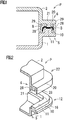
- a welding rib (11, 21) is raised along the shape thereof (see, for example, FIGS. 1 and 2 ).
- the resin member (1, 2) has, on its welded end side, a corner portion (12, 22) curved in a planar direction.
- an inner wall (11a, 21a) of the welding rib is formed in an arc shape having a curvature radius (r2) smaller than a curvature radius (r1) of an arc (14, 24) forming an inner surface (13, 23) on the welded end side of the resin member (1, 2), and has a convex portion (16, 26) protruding toward the inside of the corner portion (see, for example, FIGS. 3 and 4 ).
- the welding rib structure for example, there is indicated a form in which a flange (10, 20) is provided on the welded end side of the resin member (1, 2) so as to project outward and the welding rib (11, 21) is raised at an intermediate portion in a projecting direction on the flange (for example, see FIGS. 3 and 4 ).
- the welding rib structure for example, there is indicated a form in which the convex portion (16, 26) is arranged at a central portion in an arc direction of the inner wall (11a, 21a) of the welding rib (for example, see FIGS. 3 and 4 ).
- the welding rib structure for example, there is indicated a form in which the convex portion (16, 26) is provided over a height direction of the rising of the inner wall (11a, 21a) of the welding rib (for example, see FIGS. 5 and 6 ).
- the welding rib structure according to the present embodiment for example, there is indicated a form in which the rising end side of the welding rib (11, 21) is formed in a tapered shape (see, for example, FIG. 7 ).
- a resin product P according to the present Example includes a first resin member 1 and a second resin member 2 that is welded to the first resin member 1 and forms an internal space 3 between the first resin member 1 and the second resin member 2 itself.
- the first and second resin members 1 and 2 are each formed in the shape of a case having an opening. Further, the internal space 3 is used as a flow path space where a fluid flows.
- the first resin member 1 is provided with a first welding rib structure 5
- the second resin member 2 is provided with a second welding rib structure 6.
- a welding rib 11 is raised on the welded end side of the first resin member 1 along the shape thereof.
- a flange 10 is provided so as to project outward, and the welding rib 11 is arranged at an intermediate portion in a projecting direction on the flange 10.
- the first resin member 1 has, on its welded end side, a corner portion 12 curved in a planar direction.
- an inner wall 11a of the welding rib 11 is formed in an arc shape having a curvature radius r2 (for example, 4 mm) smaller than a curvature radius r1 (for example, 5 mm) of an arc forming an inner surface 13 located on the welded end side of the first resin member 1 (that is, an inner wall 10a of the flange 10).
- a semi-cylindrical convex portion 16 protruding toward the inside of the corner portion 12 (that is, toward the internal space 3) is formed on the inner wall 11a of the welding rib 11.
- the convex portion 16 is arranged at a central portion in an arc direction of the inner wall 11a of the welding rib 11. Further, the convex portion 16 is provided over a height direction of the rising of the inner wall 11 a of the welding rib 11.
- a welding rib 21 is raised on the welded end side of the second resin member 2 along the shape thereof.
- a flange 20 is provided so as to project outward, and the welding rib 21 is arranged at an intermediate portion in a projecting direction on the flange 20.
- a standing wall 28 is provided on the flange 20 along its inner and outer edges, respectively. The standing walls 28 form a burr pool space 29 between the inner and the outer walls of each of the welding ribs 11 and 21.
- the second resin member 2 has, on its welded end side, a corner portion 22 curved in a planar direction.
- an inner wall 21a of the welding rib 21 is formed in an arc shape having a curvature radius r2 (for example, 4.8 mm) smaller than a curvature radius r1 (for example, 5 mm) of an arc 24 forming an inner surface 23 on the welded end side of the second resin member 2 (that is, an inner wall 20a of the flange 20).
- a semi-cylindrical protrusion 26 protruding toward the inside of the corner portion 22 (that is, toward the internal space 3) is formed on the inner wall 21a of the welding rib 21.
- the convex portion 26 is arranged at a central portion in an arc direction of the inner wall 21a of the welding rib 21. Further, the convex portion 26 is provided over a height direction of the rising of the inner wall 21a of the welding rib 21.
- the burr pool spaces 29 formed inside the inner walls 11a and 21a of the welding ribs 11 and 21 each have a larger volume by the amount of the space surrounded by the inner wall 11a, 21a of the welding rib 11, 21 and an imaginary arc 15, 25, as compared with the conventional welding rib structure 105 (see FIG. 10 ).
- the virtual arc 15 is concentric with an arc 14 forming the inner surface 13 on the welded end side of the first resin member 1, and has a curvature radius r3 (for example, 7 mm) larger than the curvature radius r1 (for example, 5 mm) of the arc 14.
- the virtual arc 25 is concentric with an arc 24 forming the inner surface 23 on the welded end side of the second resin member 2, and has a curvature radius r3 (for example, 7.8 mm) larger than the curvature radius r1 (for example, 5 mm) of the arc 24.
- the convex portion 16, 26 is arranged outside the imaginary arc 15, 25 at the corner portion 12, 22.
- the operation of the welding rib structures 5 and 6 having the above structure will be described.
- the first and second resin members 1 and 2 are relatively vibrated in a direction perpendicular to the pressurization.
- the first resin member 1 and the second resin member 2 are integrated by vibration welding, so that a resin product P is obtained.
- the leading end sides of the welding ribs 11 and 21 are melted so that a welding burr B is generated.
- the welding burr B is generated locally inside the welding ribs 11 and 21 intensively.
- the burr pool spaces 29 located inside the welding ribs 11 and 21 are set so as to have a relatively large volume. Therefore, the welding burr B is accumulated in the burr pool spaces 29 and does not enter the internal space 3 (see FIG. 1 ).
- the welding rib 11, 21 is raised on the welded end side of the resin member 1, 2 along the shape thereof, and the resin member 1, 2 has, on its welded end, the corner portion 12, 22 curved in a planar direction.
- the inner wall 11a, 21a of the welding rib 11, 21 is formed in an arc shape having the curvature radius r2 smaller than the curvature radius r1 of the arc 14, 24 forming the inner surface 13, 23 on the welded end side of the resin member 1, 2, and has the convex portion 16, 26 protruding toward the inside of the corner portion 12, 22.
- the flange 10, 20 is provided on the welded end side of the resin member 1, 2 so as to project outward, and the welding rib 11, 21 is raised at the intermediate portion in the projecting direction on the flange 10, 20.
- the volume of the burr pool space 29 inside the welding rib 11, 21 can be further increased, and the rigidity of the welding rib 11, 21 is further enhanced.
- the convex portion 16, 26 is arranged at the central portion in the arc direction of the inner wall 11a, 21a of the welding rib 11, 21.
- the volume of the burr pool space 29 inside the welding rib 11, 21 can be further increased, and the rigidity of the welding rib 11, 21 is further enhanced.
- the convex portion 16, 26 is provided over the height direction of the rising of the inner wall 11a, 21a of the welding rib 11, 21.
- the volume of the burr pool space 29 inside the welding rib 11, 21 can be further increased, and the rigidity of the welding rib 11, 21 is further enhanced.
- the convex portion 16, 26 is arranged outside the imaginary arc 15,25 which is concentric with the arc 14, 24 forming the inner surface 13, 23 located on the welded end side of the resin member 1, 2 and has the curvature r3 larger than the curvature radius r1 of the arc 14, 24 (specifically, a value obtained by adding a distance S between the inner surface in a straight portion on the welded end side of the resin member 1, 2 and the inner wall of the welding rib 11, 21 to the curvature radius r1; see FIGS. 3 and 4 ).
- the volume of the burr pool space 29 inside the welding rib 11, 21 can be further increased, and the rigidity of the welding rib 11, 21 is further enhanced.
- the present invention is not limited to the above-described Example, and can be variously modified within the scope of the present invention depending on the purpose and use. That is, in the above Example, the rising end side of the welding rib 11, 21 is formed so as to have a substantially constant width, but the present invention is not limited thereto.
- the rising end side of the welding rib 11, 21 may be formed in a tapered shape.
- the amount of the welding burr B generated at the beginning of welding of the resin member 1, 2 is suppressed. Therefore, it is possible to more reliably suppress the protrusion of the welding burr B into the internal space 3.
- an inclined surface 31 in which the distance from the surface of the flange 10, 20 becomes larger from the inside toward the outside can be formed on the rising end side of the welding rib 11, 21.
- the form in which the flange 10, 20 with the welding rib 11, 21 erected is provided on the welded end side of the resin member 1, 2 has been exemplified, but the present invention is not limited thereto.
- the welding rib 11, 21 may be erected directly on the welded end side of the resin member 1, 2 without the flange 10, 20.
- the single convex portion 16, 26 is provided on the inner wall 11a, 21a of the welding rib 11, 21, but the present invention is not limited thereto.
- two or more convex portions 16, 26 may be provided on the inner wall 11a, 21a of the welding ribs 11, 21.
- the convex portion 16, 26 having a substantially semicircular cross section has been exemplified, but the present invention is not limited thereto.
- the convex portion 16, 26 may have a substantially polygonal cross section (for example, triangular and rectangular).
- the welding ribs 11 and 21 are provided on the welded end sides of the first and second resin members 1 and 2, respectively, but the present invention is not limited thereto.
- the ribs 11 and 21 may be provided on one of the welded end sides of the first and second resin members 1 and 2, and may not be provided on the other welded end side.
- the resin product P formed by integrating the two resin members 1 and 2 through vibration welding has been exemplified, but the present invention is not limited thereto.
- the resin product P may be formed by integrating the two resin members 1 and 2 through ultrasonic welding, laser welding, or the like.
- the use, shape, size, and the like of the resin product P in the above Example are not particularly limited.
- the resin product include a fluid supply pipe, an intake manifold, and various filters.
- the present invention is widely used as a technique for appropriately welding (particularly vibration-welding) the first resin member and the second resin member to obtain a resin product.
- a welding rib structure 5 has a welding rib 11 which is raised on the welded end side of a resin member 1 along the shape thereof.
- the resin member has, on its welded end side, a corner portion 12 curved in a planar direction.
- an inner wall 11a of the welding rib is formed in an arc shape having a curvature radius r2 smaller than a curvature radius r1 of an arc 14 forming an inner surface 13 located on the welded end side of the resin member, and has a convex portion 16 protruding toward the inside of the corner portion.
Landscapes
- Engineering & Computer Science (AREA)
- Mechanical Engineering (AREA)
- Lining Or Joining Of Plastics Or The Like (AREA)
Priority Applications (1)
| Application Number | Priority Date | Filing Date | Title |
|---|---|---|---|
| PL18212545T PL3527355T3 (pl) | 2018-02-14 | 2018-12-14 | Struktura żebra spawalniczego |
Applications Claiming Priority (1)
| Application Number | Priority Date | Filing Date | Title |
|---|---|---|---|
| JP2018024555A JP7069791B2 (ja) | 2018-02-14 | 2018-02-14 | 溶着リブ構造 |
Publications (2)
| Publication Number | Publication Date |
|---|---|
| EP3527355A1 true EP3527355A1 (de) | 2019-08-21 |
| EP3527355B1 EP3527355B1 (de) | 2021-09-08 |
Family
ID=64665536
Family Applications (1)
| Application Number | Title | Priority Date | Filing Date |
|---|---|---|---|
| EP18212545.0A Not-in-force EP3527355B1 (de) | 2018-02-14 | 2018-12-14 | Schweissrippenstruktur |
Country Status (3)
| Country | Link |
|---|---|
| EP (1) | EP3527355B1 (de) |
| JP (1) | JP7069791B2 (de) |
| PL (1) | PL3527355T3 (de) |
Cited By (1)
| Publication number | Priority date | Publication date | Assignee | Title |
|---|---|---|---|---|
| US20240342997A1 (en) * | 2023-04-17 | 2024-10-17 | Canon Kabushiki Kaisha | Manufacturing method of housing and apparatus having the same |
Families Citing this family (3)
| Publication number | Priority date | Publication date | Assignee | Title |
|---|---|---|---|---|
| EP4005799A4 (de) | 2019-07-25 | 2022-11-23 | FUJIFILM Corporation | Bildaufzeichnungsverfahren |
| JP7299847B2 (ja) * | 2020-01-16 | 2023-06-28 | 株式会社ミクニ | インテークマニホールド |
| DE102023208675A1 (de) * | 2023-09-07 | 2025-03-13 | Vitesco Technologies GmbH | Verfahren zum stoffschlüssigen Verbinden zweier Kunststoffteile, Verbindung zweier Kunststoffteile, flüssigkeitsführendes Gehäuse, modulare Pumpen-Ventileinheit und Wärmetransportmittelkreis(lauf)system |
Citations (2)
| Publication number | Priority date | Publication date | Assignee | Title |
|---|---|---|---|---|
| JPH05177712A (ja) | 1991-12-27 | 1993-07-20 | Tsuchiya Mfg Co Ltd | 合成樹脂部材の溶着方法 |
| JP2009002220A (ja) * | 2007-06-21 | 2009-01-08 | Mahle Filter Systems Japan Corp | 樹脂組立体及びその製造方法 |
Family Cites Families (3)
| Publication number | Priority date | Publication date | Assignee | Title |
|---|---|---|---|---|
| JPS63128932A (ja) * | 1986-11-19 | 1988-06-01 | Daihatsu Motor Co Ltd | 樹脂製サ−ジタンクの製造方法 |
| JPH05177711A (ja) * | 1991-12-27 | 1993-07-20 | Tsuchiya Mfg Co Ltd | 合成樹脂部材の溶着方法 |
| JP2000229360A (ja) | 1999-02-09 | 2000-08-22 | Du Pont Kk | 振動溶着の部材構造 |
-
2018
- 2018-02-14 JP JP2018024555A patent/JP7069791B2/ja not_active Expired - Fee Related
- 2018-12-14 PL PL18212545T patent/PL3527355T3/pl unknown
- 2018-12-14 EP EP18212545.0A patent/EP3527355B1/de not_active Not-in-force
Patent Citations (2)
| Publication number | Priority date | Publication date | Assignee | Title |
|---|---|---|---|---|
| JPH05177712A (ja) | 1991-12-27 | 1993-07-20 | Tsuchiya Mfg Co Ltd | 合成樹脂部材の溶着方法 |
| JP2009002220A (ja) * | 2007-06-21 | 2009-01-08 | Mahle Filter Systems Japan Corp | 樹脂組立体及びその製造方法 |
Cited By (1)
| Publication number | Priority date | Publication date | Assignee | Title |
|---|---|---|---|---|
| US20240342997A1 (en) * | 2023-04-17 | 2024-10-17 | Canon Kabushiki Kaisha | Manufacturing method of housing and apparatus having the same |
Also Published As
| Publication number | Publication date |
|---|---|
| JP7069791B2 (ja) | 2022-05-18 |
| PL3527355T3 (pl) | 2021-12-20 |
| EP3527355B1 (de) | 2021-09-08 |
| JP2019137001A (ja) | 2019-08-22 |
Similar Documents
| Publication | Publication Date | Title |
|---|---|---|
| EP3527355B1 (de) | Schweissrippenstruktur | |
| US9334642B1 (en) | Connection structure of column and beam, and reinforcing member | |
| CN107804158A (zh) | 燃料箱 | |
| US10228134B2 (en) | Damper for gas turbine | |
| JP4884408B2 (ja) | コリオリ流量計 | |
| WO2014112236A1 (ja) | 燃料タンク構造 | |
| US7823888B2 (en) | Gasket | |
| WO2015076228A1 (ja) | フランジ構造 | |
| US7182543B2 (en) | Joining structure | |
| JP2009210049A (ja) | ガスケット | |
| JP2017110520A (ja) | 吸気マニホルド | |
| JP2017526837A (ja) | 固定式の又は移動可能な粘性物質ポンプのための分配ブーム | |
| JP5815076B2 (ja) | オイルストレーナ | |
| JP2021165166A (ja) | 消防車用の樹脂製タンク | |
| JP2018159193A (ja) | 梁補強金具および梁補強構造 | |
| JP6298271B2 (ja) | 柱と梁との接合構造および補強部材 | |
| WO2017179384A1 (ja) | ボルト締結構造およびこれを用いたターボ機械 | |
| JP2011179618A (ja) | ガスケット及び密封構造 | |
| JP5037596B2 (ja) | 柱の接合用部材、柱の接合構造 | |
| WO2016056484A1 (ja) | 吸気音低減装置 | |
| JP6287640B2 (ja) | タンク装置 | |
| JP2012052453A (ja) | オイルストレーナ | |
| KR102886373B1 (ko) | 벤투리 실험장치 | |
| WO2021153193A1 (ja) | ダクト | |
| JP7537976B2 (ja) | 燃料ポンプの支持構造 |
Legal Events
| Date | Code | Title | Description |
|---|---|---|---|
| PUAI | Public reference made under article 153(3) epc to a published international application that has entered the european phase |
Free format text: ORIGINAL CODE: 0009012 |
|
| STAA | Information on the status of an ep patent application or granted ep patent |
Free format text: STATUS: REQUEST FOR EXAMINATION WAS MADE |
|
| 17P | Request for examination filed |
Effective date: 20181214 |
|
| AK | Designated contracting states |
Kind code of ref document: A1 Designated state(s): AL AT BE BG CH CY CZ DE DK EE ES FI FR GB GR HR HU IE IS IT LI LT LU LV MC MK MT NL NO PL PT RO RS SE SI SK SM TR |
|
| AX | Request for extension of the european patent |
Extension state: BA ME |
|
| GRAP | Despatch of communication of intention to grant a patent |
Free format text: ORIGINAL CODE: EPIDOSNIGR1 |
|
| STAA | Information on the status of an ep patent application or granted ep patent |
Free format text: STATUS: GRANT OF PATENT IS INTENDED |
|
| RIC1 | Information provided on ipc code assigned before grant |
Ipc: B29K 101/12 20060101ALN20210503BHEP Ipc: B29C 65/16 20060101ALN20210503BHEP Ipc: B29C 65/08 20060101ALN20210503BHEP Ipc: B29C 65/06 20060101AFI20210503BHEP |
|
| INTG | Intention to grant announced |
Effective date: 20210519 |
|
| RIN1 | Information on inventor provided before grant (corrected) |
Inventor name: SAITO, YASUHIRO Inventor name: OHASHI, JUNICHI |
|
| GRAS | Grant fee paid |
Free format text: ORIGINAL CODE: EPIDOSNIGR3 |
|
| GRAA | (expected) grant |
Free format text: ORIGINAL CODE: 0009210 |
|
| STAA | Information on the status of an ep patent application or granted ep patent |
Free format text: STATUS: THE PATENT HAS BEEN GRANTED |
|
| AK | Designated contracting states |
Kind code of ref document: B1 Designated state(s): AL AT BE BG CH CY CZ DE DK EE ES FI FR GB GR HR HU IE IS IT LI LT LU LV MC MK MT NL NO PL PT RO RS SE SI SK SM TR |
|
| REG | Reference to a national code |
Ref country code: GB Ref legal event code: FG4D |
|
| REG | Reference to a national code |
Ref country code: CH Ref legal event code: EP Ref country code: AT Ref legal event code: REF Ref document number: 1428211 Country of ref document: AT Kind code of ref document: T Effective date: 20210915 |
|
| REG | Reference to a national code |
Ref country code: DE Ref legal event code: R096 Ref document number: 602018023185 Country of ref document: DE |
|
| REG | Reference to a national code |
Ref country code: IE Ref legal event code: FG4D |
|
| REG | Reference to a national code |
Ref country code: LT Ref legal event code: MG9D |
|
| REG | Reference to a national code |
Ref country code: NL Ref legal event code: MP Effective date: 20210908 |
|
| PG25 | Lapsed in a contracting state [announced via postgrant information from national office to epo] |
Ref country code: LT Free format text: LAPSE BECAUSE OF FAILURE TO SUBMIT A TRANSLATION OF THE DESCRIPTION OR TO PAY THE FEE WITHIN THE PRESCRIBED TIME-LIMIT Effective date: 20210908 Ref country code: BG Free format text: LAPSE BECAUSE OF FAILURE TO SUBMIT A TRANSLATION OF THE DESCRIPTION OR TO PAY THE FEE WITHIN THE PRESCRIBED TIME-LIMIT Effective date: 20211208 Ref country code: NO Free format text: LAPSE BECAUSE OF FAILURE TO SUBMIT A TRANSLATION OF THE DESCRIPTION OR TO PAY THE FEE WITHIN THE PRESCRIBED TIME-LIMIT Effective date: 20211208 Ref country code: RS Free format text: LAPSE BECAUSE OF FAILURE TO SUBMIT A TRANSLATION OF THE DESCRIPTION OR TO PAY THE FEE WITHIN THE PRESCRIBED TIME-LIMIT Effective date: 20210908 Ref country code: SE Free format text: LAPSE BECAUSE OF FAILURE TO SUBMIT A TRANSLATION OF THE DESCRIPTION OR TO PAY THE FEE WITHIN THE PRESCRIBED TIME-LIMIT Effective date: 20210908 Ref country code: HR Free format text: LAPSE BECAUSE OF FAILURE TO SUBMIT A TRANSLATION OF THE DESCRIPTION OR TO PAY THE FEE WITHIN THE PRESCRIBED TIME-LIMIT Effective date: 20210908 Ref country code: ES Free format text: LAPSE BECAUSE OF FAILURE TO SUBMIT A TRANSLATION OF THE DESCRIPTION OR TO PAY THE FEE WITHIN THE PRESCRIBED TIME-LIMIT Effective date: 20210908 Ref country code: FI Free format text: LAPSE BECAUSE OF FAILURE TO SUBMIT A TRANSLATION OF THE DESCRIPTION OR TO PAY THE FEE WITHIN THE PRESCRIBED TIME-LIMIT Effective date: 20210908 |
|
| PGFP | Annual fee paid to national office [announced via postgrant information from national office to epo] |
Ref country code: FR Payment date: 20211220 Year of fee payment: 4 |
|
| REG | Reference to a national code |
Ref country code: AT Ref legal event code: MK05 Ref document number: 1428211 Country of ref document: AT Kind code of ref document: T Effective date: 20210908 |
|
| PG25 | Lapsed in a contracting state [announced via postgrant information from national office to epo] |
Ref country code: LV Free format text: LAPSE BECAUSE OF FAILURE TO SUBMIT A TRANSLATION OF THE DESCRIPTION OR TO PAY THE FEE WITHIN THE PRESCRIBED TIME-LIMIT Effective date: 20210908 Ref country code: GR Free format text: LAPSE BECAUSE OF FAILURE TO SUBMIT A TRANSLATION OF THE DESCRIPTION OR TO PAY THE FEE WITHIN THE PRESCRIBED TIME-LIMIT Effective date: 20211209 |
|
| PG25 | Lapsed in a contracting state [announced via postgrant information from national office to epo] |
Ref country code: AT Free format text: LAPSE BECAUSE OF FAILURE TO SUBMIT A TRANSLATION OF THE DESCRIPTION OR TO PAY THE FEE WITHIN THE PRESCRIBED TIME-LIMIT Effective date: 20210908 |
|
| PGFP | Annual fee paid to national office [announced via postgrant information from national office to epo] |
Ref country code: DE Payment date: 20211222 Year of fee payment: 4 |
|
| PG25 | Lapsed in a contracting state [announced via postgrant information from national office to epo] |
Ref country code: IS Free format text: LAPSE BECAUSE OF FAILURE TO SUBMIT A TRANSLATION OF THE DESCRIPTION OR TO PAY THE FEE WITHIN THE PRESCRIBED TIME-LIMIT Effective date: 20220108 Ref country code: SM Free format text: LAPSE BECAUSE OF FAILURE TO SUBMIT A TRANSLATION OF THE DESCRIPTION OR TO PAY THE FEE WITHIN THE PRESCRIBED TIME-LIMIT Effective date: 20210908 Ref country code: SK Free format text: LAPSE BECAUSE OF FAILURE TO SUBMIT A TRANSLATION OF THE DESCRIPTION OR TO PAY THE FEE WITHIN THE PRESCRIBED TIME-LIMIT Effective date: 20210908 Ref country code: RO Free format text: LAPSE BECAUSE OF FAILURE TO SUBMIT A TRANSLATION OF THE DESCRIPTION OR TO PAY THE FEE WITHIN THE PRESCRIBED TIME-LIMIT Effective date: 20210908 Ref country code: PT Free format text: LAPSE BECAUSE OF FAILURE TO SUBMIT A TRANSLATION OF THE DESCRIPTION OR TO PAY THE FEE WITHIN THE PRESCRIBED TIME-LIMIT Effective date: 20220110 Ref country code: NL Free format text: LAPSE BECAUSE OF FAILURE TO SUBMIT A TRANSLATION OF THE DESCRIPTION OR TO PAY THE FEE WITHIN THE PRESCRIBED TIME-LIMIT Effective date: 20210908 Ref country code: EE Free format text: LAPSE BECAUSE OF FAILURE TO SUBMIT A TRANSLATION OF THE DESCRIPTION OR TO PAY THE FEE WITHIN THE PRESCRIBED TIME-LIMIT Effective date: 20210908 Ref country code: CZ Free format text: LAPSE BECAUSE OF FAILURE TO SUBMIT A TRANSLATION OF THE DESCRIPTION OR TO PAY THE FEE WITHIN THE PRESCRIBED TIME-LIMIT Effective date: 20210908 Ref country code: AL Free format text: LAPSE BECAUSE OF FAILURE TO SUBMIT A TRANSLATION OF THE DESCRIPTION OR TO PAY THE FEE WITHIN THE PRESCRIBED TIME-LIMIT Effective date: 20210908 |
|
| REG | Reference to a national code |
Ref country code: DE Ref legal event code: R097 Ref document number: 602018023185 Country of ref document: DE |
|
| PLBE | No opposition filed within time limit |
Free format text: ORIGINAL CODE: 0009261 |
|
| STAA | Information on the status of an ep patent application or granted ep patent |
Free format text: STATUS: NO OPPOSITION FILED WITHIN TIME LIMIT |
|
| PG25 | Lapsed in a contracting state [announced via postgrant information from national office to epo] |
Ref country code: MC Free format text: LAPSE BECAUSE OF FAILURE TO SUBMIT A TRANSLATION OF THE DESCRIPTION OR TO PAY THE FEE WITHIN THE PRESCRIBED TIME-LIMIT Effective date: 20210908 Ref country code: DK Free format text: LAPSE BECAUSE OF FAILURE TO SUBMIT A TRANSLATION OF THE DESCRIPTION OR TO PAY THE FEE WITHIN THE PRESCRIBED TIME-LIMIT Effective date: 20210908 |
|
| REG | Reference to a national code |
Ref country code: CH Ref legal event code: PL |
|
| 26N | No opposition filed |
Effective date: 20220609 |
|
| PG25 | Lapsed in a contracting state [announced via postgrant information from national office to epo] |
Ref country code: SI Free format text: LAPSE BECAUSE OF FAILURE TO SUBMIT A TRANSLATION OF THE DESCRIPTION OR TO PAY THE FEE WITHIN THE PRESCRIBED TIME-LIMIT Effective date: 20210908 |
|
| PGFP | Annual fee paid to national office [announced via postgrant information from national office to epo] |
Ref country code: PL Payment date: 20211203 Year of fee payment: 4 |
|
| REG | Reference to a national code |
Ref country code: BE Ref legal event code: MM Effective date: 20211231 |
|
| PG25 | Lapsed in a contracting state [announced via postgrant information from national office to epo] |
Ref country code: LU Free format text: LAPSE BECAUSE OF NON-PAYMENT OF DUE FEES Effective date: 20211214 Ref country code: IE Free format text: LAPSE BECAUSE OF NON-PAYMENT OF DUE FEES Effective date: 20211214 |
|
| PG25 | Lapsed in a contracting state [announced via postgrant information from national office to epo] |
Ref country code: BE Free format text: LAPSE BECAUSE OF NON-PAYMENT OF DUE FEES Effective date: 20211231 |
|
| PG25 | Lapsed in a contracting state [announced via postgrant information from national office to epo] |
Ref country code: LI Free format text: LAPSE BECAUSE OF NON-PAYMENT OF DUE FEES Effective date: 20211231 Ref country code: CH Free format text: LAPSE BECAUSE OF NON-PAYMENT OF DUE FEES Effective date: 20211231 |
|
| PG25 | Lapsed in a contracting state [announced via postgrant information from national office to epo] |
Ref country code: IT Free format text: LAPSE BECAUSE OF FAILURE TO SUBMIT A TRANSLATION OF THE DESCRIPTION OR TO PAY THE FEE WITHIN THE PRESCRIBED TIME-LIMIT Effective date: 20210908 |
|
| PG25 | Lapsed in a contracting state [announced via postgrant information from national office to epo] |
Ref country code: CY Free format text: LAPSE BECAUSE OF FAILURE TO SUBMIT A TRANSLATION OF THE DESCRIPTION OR TO PAY THE FEE WITHIN THE PRESCRIBED TIME-LIMIT Effective date: 20210908 |
|
| REG | Reference to a national code |
Ref country code: DE Ref legal event code: R119 Ref document number: 602018023185 Country of ref document: DE |
|
| PG25 | Lapsed in a contracting state [announced via postgrant information from national office to epo] |
Ref country code: HU Free format text: LAPSE BECAUSE OF FAILURE TO SUBMIT A TRANSLATION OF THE DESCRIPTION OR TO PAY THE FEE WITHIN THE PRESCRIBED TIME-LIMIT; INVALID AB INITIO Effective date: 20181214 |
|
| GBPC | Gb: european patent ceased through non-payment of renewal fee |
Effective date: 20221214 |
|
| PG25 | Lapsed in a contracting state [announced via postgrant information from national office to epo] |
Ref country code: GB Free format text: LAPSE BECAUSE OF NON-PAYMENT OF DUE FEES Effective date: 20221214 Ref country code: DE Free format text: LAPSE BECAUSE OF NON-PAYMENT OF DUE FEES Effective date: 20230701 |
|
| PG25 | Lapsed in a contracting state [announced via postgrant information from national office to epo] |
Ref country code: FR Free format text: LAPSE BECAUSE OF NON-PAYMENT OF DUE FEES Effective date: 20221231 |
|
| PG25 | Lapsed in a contracting state [announced via postgrant information from national office to epo] |
Ref country code: MK Free format text: LAPSE BECAUSE OF FAILURE TO SUBMIT A TRANSLATION OF THE DESCRIPTION OR TO PAY THE FEE WITHIN THE PRESCRIBED TIME-LIMIT Effective date: 20210908 |
|
| PG25 | Lapsed in a contracting state [announced via postgrant information from national office to epo] |
Ref country code: PL Free format text: LAPSE BECAUSE OF NON-PAYMENT OF DUE FEES Effective date: 20221214 |
|
| PG25 | Lapsed in a contracting state [announced via postgrant information from national office to epo] |
Ref country code: TR Free format text: LAPSE BECAUSE OF FAILURE TO SUBMIT A TRANSLATION OF THE DESCRIPTION OR TO PAY THE FEE WITHIN THE PRESCRIBED TIME-LIMIT Effective date: 20210908 |
|
| PG25 | Lapsed in a contracting state [announced via postgrant information from national office to epo] |
Ref country code: MT Free format text: LAPSE BECAUSE OF FAILURE TO SUBMIT A TRANSLATION OF THE DESCRIPTION OR TO PAY THE FEE WITHIN THE PRESCRIBED TIME-LIMIT Effective date: 20210908 |