EP3527825B1 - Vorrichtung zur erzeugung von druckluft - Google Patents
Vorrichtung zur erzeugung von druckluft Download PDFInfo
- Publication number
- EP3527825B1 EP3527825B1 EP19155485.6A EP19155485A EP3527825B1 EP 3527825 B1 EP3527825 B1 EP 3527825B1 EP 19155485 A EP19155485 A EP 19155485A EP 3527825 B1 EP3527825 B1 EP 3527825B1
- Authority
- EP
- European Patent Office
- Prior art keywords
- valve
- compressed
- air
- compressed air
- shut
- Prior art date
- Legal status (The legal status is an assumption and is not a legal conclusion. Google has not performed a legal analysis and makes no representation as to the accuracy of the status listed.)
- Active
Links
Images

Classifications
-
- F—MECHANICAL ENGINEERING; LIGHTING; HEATING; WEAPONS; BLASTING
- F04—POSITIVE - DISPLACEMENT MACHINES FOR LIQUIDS; PUMPS FOR LIQUIDS OR ELASTIC FLUIDS
- F04B—POSITIVE-DISPLACEMENT MACHINES FOR LIQUIDS; PUMPS
- F04B49/00—Control, e.g. of pump delivery, or pump pressure of, or safety measures for, machines, pumps, or pumping installations, not otherwise provided for, or of interest apart from, groups F04B1/00 - F04B47/00
- F04B49/02—Stopping, starting, unloading or idling control
- F04B49/03—Stopping, starting, unloading or idling control by means of valves
-
- F—MECHANICAL ENGINEERING; LIGHTING; HEATING; WEAPONS; BLASTING
- F04—POSITIVE - DISPLACEMENT MACHINES FOR LIQUIDS; PUMPS FOR LIQUIDS OR ELASTIC FLUIDS
- F04B—POSITIVE-DISPLACEMENT MACHINES FOR LIQUIDS; PUMPS
- F04B39/00—Component parts, details, or accessories, of pumps or pumping systems specially adapted for elastic fluids, not otherwise provided for in, or of interest apart from, groups F04B25/00 - F04B37/00
- F04B39/12—Casings; Cylinders; Cylinder heads; Fluid connections
- F04B39/121—Casings
-
- F—MECHANICAL ENGINEERING; LIGHTING; HEATING; WEAPONS; BLASTING
- F04—POSITIVE - DISPLACEMENT MACHINES FOR LIQUIDS; PUMPS FOR LIQUIDS OR ELASTIC FLUIDS
- F04B—POSITIVE-DISPLACEMENT MACHINES FOR LIQUIDS; PUMPS
- F04B39/00—Component parts, details, or accessories, of pumps or pumping systems specially adapted for elastic fluids, not otherwise provided for in, or of interest apart from, groups F04B25/00 - F04B37/00
- F04B39/12—Casings; Cylinders; Cylinder heads; Fluid connections
- F04B39/123—Fluid connections
-
- F—MECHANICAL ENGINEERING; LIGHTING; HEATING; WEAPONS; BLASTING
- F04—POSITIVE - DISPLACEMENT MACHINES FOR LIQUIDS; PUMPS FOR LIQUIDS OR ELASTIC FLUIDS
- F04B—POSITIVE-DISPLACEMENT MACHINES FOR LIQUIDS; PUMPS
- F04B41/00—Pumping installations or systems specially adapted for elastic fluids
-
- F—MECHANICAL ENGINEERING; LIGHTING; HEATING; WEAPONS; BLASTING
- F04—POSITIVE - DISPLACEMENT MACHINES FOR LIQUIDS; PUMPS FOR LIQUIDS OR ELASTIC FLUIDS
- F04B—POSITIVE-DISPLACEMENT MACHINES FOR LIQUIDS; PUMPS
- F04B49/00—Control, e.g. of pump delivery, or pump pressure of, or safety measures for, machines, pumps, or pumping installations, not otherwise provided for, or of interest apart from, groups F04B1/00 - F04B47/00
- F04B49/22—Control, e.g. of pump delivery, or pump pressure of, or safety measures for, machines, pumps, or pumping installations, not otherwise provided for, or of interest apart from, groups F04B1/00 - F04B47/00 by means of valves
- F04B49/24—Bypassing
- F04B49/246—Bypassing by keeping open the outlet valve
Definitions
- the invention relates to a device, in particular a compressor, for generating compressed air for a utility vehicle.
- the DE 821 641 C discloses an automatic start-up and control device for refrigeration systems.
- a valve is built into the cylinder head of the compressor, which is controlled depending on the power consumption of the drive motor or depending on the evaporation temperature and allows part of the refrigerant to flow back from the pressure chamber into the cylinder of the compressor or into the suction side.
- the compressor has a housing with a piston space and a separate dead space and a valve device with a shut-off body for separating the dead space from the piston space.
- the dead space is arranged separately from an air inlet duct and a compressed air outlet duct.
- a disadvantage of the known prior art can be that the dead space can take up a lot of space in the cylinder head or the volume of the dead space cannot be optimally designed due to the tight space in the cylinder head of the compressor.
- the invention is based on the object of creating an alternative and / or improved device for generating compressed air which in particular overcomes at least some disadvantages in the prior art.
- the invention creates a device, in particular a compressor (e.g. piston compressor), for generating compressed air (in particular) for a utility vehicle (e.g. for a compressed air brake system of the utility vehicle).
- the device has a compression chamber (e.g. piston chamber) for compressing air into compressed air.
- the device has a compressed air outlet channel (for example in a cylinder head of the device) for discharging compressed air from the Compression area.
- the device has an outlet valve, via which the compression chamber and the compressed air outlet channel can be connected to one another (e.g. for the output of compressed air in one outlet cycle).
- the device has an additional valve (in particular) for an energy-saving mode (in particular for relieving a drive) of the device.
- the compression chamber and the compressed air outlet duct can be connected via the additional valve (e.g. in addition to the outlet valve).
- the additional valve e.g. in addition to the outlet valve.
- the compressed air outlet channel can be used at least partially as a switchable dead space (e.g. switchable to the compression space) when the additional valve is open.
- the invention thus creates a device in which the switchable dead space for the energy-saving mode, in which the compressor or a drive of the compressor can be relieved, is not provided separately or individually. Instead, the dead space is at least partially integrated into the compressed air outlet channel. That is to say that the volume of the compressed air outlet channel which is already present can at least partially be used as the dead space. It is therefore not necessary to provide additional installation space for providing the dead space. As a result of the installation space saved, the device can be made smaller, for example, and / or additional space is created for other elements (for example air inlet duct, inlet valve, additional valve, compressed air outlet duct, outlet valve, cooling device and / or cooling duct).
- the switchable dead space for the energy-saving mode in which the compressor or a drive of the compressor can be relieved
- the device can expediently be a single-cylinder compressor.
- the device can furthermore have an air inlet duct and an inlet valve, via which the air inlet duct and the compression chamber can be connected to one another.
- the air inlet duct, the inlet valve, the compressed air outlet duct, the outlet valve and / or the additional valve it is possible for the air inlet duct, the inlet valve, the compressed air outlet duct, the outlet valve and / or the additional valve to be arranged in a cylinder head of the device.
- the device can be drivingly connected to an internal combustion engine for driving the device.
- air is compressed through the opened additional valve into the dead space that can be activated.
- air can be compressed from the compression space through the opened additional valve into the connectable dead space.
- the compressed air present in the dead space is expediently available for a subsequent re-expansion into the compression space.
- compressed air in the energy-saving mode, is expanded back into the compression chamber from the connectable dead space through the open additional valve, in particular to drive a piston of the device.
- compressed air can be expanded back into the compression chamber through the open additional valve during a piston movement of a piston of the device from a top dead center to a bottom dead center.
- the re-expanding gas can drive the piston and thus reduce the energy required to drive the device in the energy-saving mode, in which no (additional) compressed air is required by the device.
- the connectable dead space is arranged at least partially outside of a cylinder head of the device.
- the connectable dead space is at least partially arranged within a cylinder head of the device. In this way, a volume of the connectable dead space can be adapted as desired, for example by extending the dead space into compressed air routing components downstream of the device, in particular the compressor.
- the additional valve is (essentially) open in the energy-saving mode, in particular continuously.
- the additional valve is (essentially) closed in normal compression mode of the device, in particular continuously. This means that air can only flow through the additional valve in energy-saving mode.
- the normal compression mode can be used in particular to provide compressed air by the device, in particular when compressed air is required by the device, for example to fill up a compressed air reservoir.
- the additional valve can be normally closed.
- the additional valve pretensions or acts upon a shut-off body of the additional valve in the direction of a closed position.
- the outlet valve is (essentially) closed in the energy-saving mode, in particular continuously, and / or the outlet valve is (essentially) open in the outlet cycle in normal compression mode of the device. This means that no air can flow through the outlet valve in energy-saving mode.
- the outlet valve opens automatically due to a pressure difference between the compression chamber and the compressed air outlet channel.
- the exhaust valve can open automatically in the exhaust or compression stroke and / or close automatically in the intake or intake stroke.
- the outlet valve is designed as a lamella valve (for example with a movable lamella).
- the movable lamella can open in the direction of the compressed air outlet channel and / or in particular be fastened on one side to a cylinder head of the device.
- the device also has a shut-off valve, in particular a pneumatically operated shut-off valve, which can preferably be arranged in the compressed air outlet channel and / or downstream of the compressed air outlet channel. It is possible, for example, that a volume of the dead space that can be switched on can be predetermined or limited by means of the shut-off valve.
- a shut-off valve in particular a pneumatically operated shut-off valve, which can preferably be arranged in the compressed air outlet channel and / or downstream of the compressed air outlet channel. It is possible, for example, that a volume of the dead space that can be switched on can be predetermined or limited by means of the shut-off valve.
- the shut-off valve is closed, in particular continuously, in the energy-saving mode of the device.
- the shut-off valve is open in normal compression mode of the device, in particular continuously.
- shut-off valve can be switchable, for example pneumatically, between an open position and a closed position.
- the shut-off valve in a closed position, delimits the dead space that can be switched on, in particular on the downstream side.
- the connectable dead space can only exist when the shut-off valve is in the closed position.
- the additional valve can limit the connectable dead space on the upstream side.
- the additional valve can expediently represent a transition between the compression space and the dead space that can be activated.
- the shut-off valve is positioned in such a way that a (e.g. optimized) volume required for executing the energy-saving mode is available for the connectable dead space, in particular as a function of a volume of the compression chamber and / or a compression ratio of the device.
- a size of the volume of the connectable dead space can thus be set as desired.
- the size of the volume of the connectable dead space is not restricted by the installation space in the cylinder head.
- the dead space can thus be provided, for example, larger than usual.
- the additional valve is designed separately from the outlet valve or as an integrated valve unit together with the outlet valve. This means that the valves can be adapted to the existing installation space, for example. Alternatively or additionally, the outlet valve and the additional valve have separate shut-off bodies.
- actuation of the additional valve and / or the shut-off valve is controlled by an, in particular electronic, compressed air processing device, in particular pneumatically.
- an, in particular electronic, compressed air processing device in particular pneumatically.
- the additional valve and the shut-off valve are controlled via the same pneumatic control pressure line and / or the same control pressure connection of an, in particular electronic, compressed air processing device.
- the additional valve and the shut-off valve can expediently be switched (e.g. opened or closed) at the same time. For this only a single control output has to be set accordingly.
- the additional valve can be switched, in particular pneumatically, electrically or electromagnetically, between an open position and a closed position.
- the additional valve can be a pneumatic valve or a solenoid valve.
- the invention is also directed to a device, in particular a compressed air delivery system, for generating compressed air for a commercial vehicle (in particular for a compressed air brake system).
- the device has a device for generating compressed air, in particular a compressor, as disclosed herein.
- the device has a connecting line, in particular a cooling coil for cooling the compressed air, which is arranged (for example directly or indirectly) downstream of the compressed air outlet channel.
- the device has an air dryer which is arranged downstream of the compressed air outlet duct (for example downstream of the connecting line).
- the shut-off valve can be arranged in the compressed air outlet channel, downstream from the compressed air outlet channel, upstream from the connecting line, in the connecting line, downstream from the connecting line, upstream from the air dryer, in the air dryer or downstream from the air dryer.
- shut-off valve it is also possible for the shut-off valve to be arranged in an, in particular electronic, compressed air processing device with an air dryer.
- the connecting line can be provided outside of the cylinder head and / or connected directly to the compressed air outlet channel arranged in the cylinder head.
- shut-off valve is arranged upstream of the air dryer, which is arranged downstream of the connecting line, in particular is connected directly to the connecting line, a conventional air dryer can be used, for example.
- the connecting line can extend straight or be provided in the form of a cooling coil with, for example, a winding course.
- the air dryer can expediently be arranged in the electronic compressed air processing device.
- the invention is also directed to a motor vehicle, in particular a utility vehicle (for example a truck or omnibus), with a device as disclosed herein or a device as disclosed herein.
- a motor vehicle in particular a utility vehicle (for example a truck or omnibus), with a device as disclosed herein or a device as disclosed herein.
- a compressed air conveyor system 10 is shown in sections.
- the compressed air delivery system 10 can be included in a motor vehicle, in particular a utility vehicle (for example a truck or bus).
- the compressed air delivery system 10 can be part of a compressed air brake system of a commercial vehicle.
- the compressed air delivery system 10 has a compressor 12.
- the compressor (also called an air compressor) 12 is used to compress popular air into compressed air.
- the compressor 12 can be designed, for example, as a reciprocating compressor with a reciprocating piston 14.
- the piston 14 can, for example, be driven by an internal combustion engine of the motor vehicle, in particular coupled to its speed, via a drive connection (not shown), for example having a crankshaft and / or a gear drive.
- the compressor 12 has a cylinder head 16 and a cylinder 18.
- the cylinder head 16 covers the cylinder 18.
- the piston 14 is guided in the cylinder 18.
- An air inlet duct 20 and a compressed air outlet duct 22 are provided in the cylinder head 16.
- the cylinder head 16, the cylinder 18 and the piston 14 delimit a compression space 24.
- air is compressed into compressed air when the driven piston 14 is moved from a bottom dead center to a top dead center of a piston movement of the piston 14.
- a cooling device and / or a cooling duct both not shown) for cooling the compressor 12 can be provided in the cylinder head 16, for example.
- the compressor 12 has an inlet valve 26 (in a closed position in the Figures 1 to 3 shown).
- the inlet valve 26 can open automatically when there is a sufficiently large (negative) pressure difference between the air inlet duct 20 and the compression chamber 24.
- the inlet valve 26 can be a reed valve.
- the lamella of the inlet valve 26 can be fastened in or on the cylinder head 16, in particular on one side.
- the lamella of the inlet valve 26 can open in a direction towards the compression chamber 24 if a pressure in the compression chamber 24 is lower than in the air inlet duct 20.
- the inlet valve 26 connects the air inlet duct 20 and the compression chamber 24 to one another.
- the inlet valve 26 separates or isolates the air inlet duct 20 and the compression chamber 24 from one another.
- the compressor 12 has an outlet valve 28 (in a closed position in the Figures 1 to 3 shown).
- the outlet valve 28 can be designed essentially like the inlet valve 26.
- the outlet valve 28 can open automatically when there is a sufficiently large (positive) pressure difference between the compression chamber 24 and the compressed air outlet channel 22.
- the outlet valve 28 can also be a reed valve.
- the lamella of the exhaust valve 28 can be fastened in or on the cylinder head 16, in particular on one side.
- the lamella of the outlet valve 28 can open in a direction towards the compressed air outlet channel 22 if a pressure in the compression chamber 24 is greater than in the compressed air outlet channel 22.
- the air outlet valve 28 connects the compression chamber 24 and the compressed air outlet channel 22 to one another.
- no air can flow through the outlet valve 28 between the compression chamber 24 and the compressed air outlet channel 22.
- air from the environment can be sucked into the compression chamber 24 via the air inlet channel 20 and the open inlet valve 24 (arrow A - inlet cycle or intake cycle).
- the piston 14 moves from a top dead center of a piston movement of the piston 14 to a bottom dead center of the piston movement.
- the outlet valve 28 remains closed.
- compressed air can leave the compressor 12 from the compression chamber 24 via the open outlet valve 28 and the compressed air outlet channel 22 (arrow B - outlet cycle or compression cycle).
- the piston 14 moves from the bottom dead center to the top dead center.
- the inlet valve 24 remains closed.
- the compressed air from the compressor 12 is fed via a connecting line 30 to a compressed air processing device 32.
- the connecting line 30 can be connected directly to an outlet of the compressed air outlet channel 22.
- the connecting line 30 can be designed as a straight or curved pipe section. It is also possible that the connecting line 30 is designed as a so-called cooling coil. Due to its, for example, coiled shape, the cooling coil can enable the compressed air to be cooled due to the large surface area.
- the compressed air processing device 32 can in particular be designed as an electronic (or electronically controlled) compressed air processing device.
- the compressed air made available by the compressor 12 can be prepared (for example distributed, collected, dried and / or cooled, etc.) for subsequent use.
- An air dryer 34 for drying compressed air can be included in the compressed air processing device 32.
- a shut-off valve 36 can be provided upstream or downstream of the air dryer 34.
- the compressed air processing device 32 can also have one or more sensors (in particular compressed air sensors), switching valves, compressed air reservoirs (not shown), etc. Examples of compressed air preparation devices that can be used as the compressed air preparation device 32 are, for example, in FIG EP 3 128 186 A1 and the EP 2 933 503 A1 disclosed.
- the compressor 12 can also be operated in an energy-saving mode. In the energy-saving mode, the mechanical drive of the compressor 12 is considerably relieved. In the energy-saving mode, no compressed air is required from the compressed air delivery system 10. Accordingly, in the energy-saving mode, the compressor 12 does not make any compressed air available for further use.
- the compressor 12 has an additional valve 38 for a dead space 42 that can be switched on.
- the additional valve 38 can be arranged in the cylinder head 16.
- the additional valve 38 is designed as a switching valve.
- the additional valve 38 can be switched between an open position and a closed position.
- the additional valve 38 can in particular be controlled or actuated pneumatically by the compressed air preparation 32 via a control pressure line 40.
- the additional valve 38 connects the compression chamber 24 and the compressed air outlet channel 22.
- a closed position of the additional valve 38 no air can flow through the additional valve 38 between the compression chamber 24 and the compressed air outlet channel 22.
- the additional valve 38 can be normally closed.
- the additional valve 38 can have a return spring which biases a shut-off body of the additional valve 38 in the direction of the closed position.
- the additional valve 38 is provided separately from the outlet valve 28. However, it is also possible for the outlet valve 28 and the additional valve 38 to be combined in an integrated valve device.
- the energy-saving mode is exemplified below with reference to FIG Figure 2 described.
- the power saving mode can be performed as follows.
- the compressed air processing device 32 it is detected that a shutdown pressure of the compressed air delivery system 10 has been reached or exceeded.
- the compressed air processing device 32 can continuously close a compressed air outlet or close whenever a regeneration (drying) of compressed air has taken place by the air dryer 34.
- the compressed air preparation device closes the shut-off valve 36.
- the compressed air preparation device 32 also activates the additional valve 38, for example pneumatically via the control pressure line 40.
- the additional valve 38 opens.
- the switchable dead space 42 By opening the additional valve 38, the switchable dead space 42 is released or switched on.
- the connectable dead space 42 extends from the additional valve 38 through the compressed air outlet channel 22, the connecting line 30 to the shut-off valve 36. That is, according to the present disclosure, the connectable dead space 42 is not provided separately, but into the compressed air tract downstream of the additional valve 38 and of the outlet valve 28 integrated.
- the piston 14 moves again from bottom dead center to top dead center.
- the air inlet valve 26 closes due to the lack of negative pressure in the compression chamber.
- the air outlet valve 28 expediently does not open due to the low pressure in the compression chamber 24.
- the open additional valve 38 compresses air into the dead space 42 that can be activated. In other words, the compressor 12 breathes air into the dead space 42 during this phase. The air is compressed into the dead space 42.
- the open additional valve 38 can be used to cyclically compress into the connected dead space 42 and then re-expand from the connected dead space 42 into the compression space 24 (see arrow C). As a result, the compressor 12 or a drive of the compressor 12 is relieved.
- a volume of the connectable dead space 42 is limited on the one hand by the additional valve 38 and on the other hand by the shut-off valve 36.
- the volume of the connectable dead space 42 can be determined as desired.
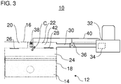
- FIG. 3 Another exemplary embodiment is shown in which the shut-off valve 36 is arranged or integrated in the connecting line 30.
- the shut-off valve 36 can be monitored electronically by the compressed air preparation device 32, as shown by the dashed line in FIG Figure 3 is specified.
- shut-off valve 36 it is also possible, for example, for the shut-off valve 36 to be arranged in or on the compressed air outlet duct 22 in or on the cylinder head 16 (not shown).
Landscapes
- Engineering & Computer Science (AREA)
- Mechanical Engineering (AREA)
- General Engineering & Computer Science (AREA)
- Compressor (AREA)
Description
- Die Erfindung betrifft eine Vorrichtung, insbesondere einen Kompressor, zur Erzeugung von Druckluft für ein Nutzfahrzeug.
- Die
DE 821 641 C offenbart eine selbsttätige Anfahr- und Regeleinrichtung für Kälteanlagen. In den Zylinderkopf des Kompressors ist ein Ventil eingebaut, das abhängig von der Stromaufnahme des Antriebsmotors oder abhängig von der Verdampfungstemperatur gesteuert wird und den Rückfluss eines Teils des Kältemittels aus dem Druckraum in den Zylinder des Kompressors oder in die Saugseite ermöglicht. - Aus der
DE 10 2008 005 435 A1 ist ein Kompressor mit einer Energiesparvorrichtung bekannt. Der Kompressor weist ein Gehäuse mit einem Kolbenraum und einem separaten Schadraum und eine Ventileinrichtung mit einem Absperrkörper zum Trennen des Schadraums von dem Kolbenraum auf. Der Schadraum ist separat zu einem Lufteinlasskanal und einem Druckluftauslasskanal angeordnet. - Zum weiteren technologischen Hintergrund wird auf die
GB 982 927 A DE 34 46 096 A1 hingewiesen. - Nachteilig am bekannten Stand der Technik kann sein, das der Schadraum viel Raum im Zylinderkopf einnehmen kann bzw. das Volumen des Schadraums nicht optimal ausgeführt werden kann aufgrund der engen Platzverhältnisse im Zylinderkopf des Kompressors.
- Der Erfindung liegt die Aufgabe zu Grunde, eine alternative und/oder verbesserte Vorrichtung zur Erzeugung von Druckluft zu schaffen, die insbesondere zumindest einige Nachteile im Stand der Technik überwindet.
- Die Aufgabe wird gelöst durch die Merkmale des unabhängigen Anspruchs. Vorteilhafte Weiterbildungen sind in den abhängigen Ansprüchen und der Beschreibung angegeben.
- Die Erfindung schafft eine Vorrichtung, insbesondere einen Kompressor (z. B. Kolbenkompressor), zur Erzeugung von Druckluft (insbesondere) für ein Nutzfahrzeug (z. B. für Druckluftbremsanlage des Nutzfahrzeugs). Die Vorrichtung weist einen Verdichtungsraum (z. B. Kolbenraum) zum Verdichten von Luft zu Druckluft auf. Die Vorrichtung weist einen Druckluftauslasskanal (z. B. in einem Zylinderkopf der Vorrichtung) zum Abführen von Druckluft aus dem Verdichtungsraum auf. Die Vorrichtung weist ein Auslassventil auf, über das der Verdichtungsraum und der Druckluftauslasskanal miteinander verbindbar sind (z. B. zum Ausgeben von Druckluft in einem Auslasstakt). Die Vorrichtung weist ein Zusatzventil (insbesondere) für einen Energiesparmodus (insbesondere zum Entlasten eines Antriebs) der Vorrichtung auf. Über das Zusatzventil sind der Verdichtungsraum und der Druckluftauslasskanal verbindbar (z. B. zusätzlich zu dem Auslassventil). Mittels des Zusatzventils ist der Druckluftauslasskanal zumindest teilweise als ein zuschaltbarer Schadraum (z. B. zuschaltbar zum Verdichtungsraum) verwendbar, wenn das Zusatzventil geöffnet ist.
- Die Erfindung schafft somit eine Vorrichtung, bei der der zuschaltbare Schadraum für den Energiesparmodus, bei dem der Kompressor bzw. ein Antrieb des Kompressors entlastet werden kann, nicht separat bzw. einzeln vorgesehen ist. Stattdessen ist der Schadraum zumindest teilweise in den Druckluftauslasskanal integriert. Das heißt, das ohnehin vorhandene Volumen des Druckluftauslasskanals kann zumindest teilweise als der Schadraum verwendet werden. Damit ist es nicht erforderlich, zusätzlichen Bauraum zum Vorsehen des Schadraums vorzusehen. Durch den eingesparten Bauraum kann die Vorrichtung beispielsweise kleiner gebaut werden und/oder es wird zusätzlicher Platz für andere Elemente (zum Beispiel Lufteinlasskanal, Einlassventil, Zusatzventil, Druckluftauslasskanal, Auslassventil, Kühlvorrichtung und/oder Kühlkanal) geschaffen.
- Zweckmäßig kann es sich bei der Vorrichtung um einen Einzylinder-Kompressor handeln.
- Insbesondere kann die Vorrichtung ferner einen Lufteinlasskanal und ein Einlassventil, über das der Lufteinlasskanal und der Verdichtungsraum miteinander verbindbar sind, aufweisen.
- Es ist möglich, dass der Lufteinlasskanal, das Einlassventil, der Druckluftauslasskanal, das Auslassventil und/oder das Zusatzventil in einem Zylinderkopf der Vorrichtung angeordnet sind.
- Insbesondere kann die Vorrichtung trieblich mit einer Brennkraftmaschine zum Antreiben der Vorrichtung verbunden sein.
- In einem bevorzugten Ausführungsbeispiel wird im Energiesparmodus Luft durch das geöffnete Zusatzventil in den zuschaltbaren Schadraum hineinverdichtet. Beispielsweise kann Luft bei einer Kolbenbewegung eines Kolbens der Vorrichtung von einem unteren Totpunkt zu einem oberen Totpunkt von dem Verdichtungsraum durch das geöffnete Zusatzventil in den zuschaltbaren Schadraum hineinverdichtet werden. Die im Schadraum vorhandene Druckluft steht zweckmäßig für eine anschließende Rückexpansion in den Verdichtungsraum zur Verfügung.
- In einem weiteren bevorzugten Ausführungsbeispiel wird im Energiesparmodus Druckluft aus dem zuschaltbaren Schadraum durch das geöffnete Zusatzventil in den Verdichtungsraum rückexpandiert, insbesondere zum Antreiben eines Kolbens der Vorrichtung. Beispielsweise kann Druckluft bei einer Kolbenbewegung eines Kolbens der Vorrichtung von einem oberen Totpunkt zu einem unteren Totpunkt aus dem zuschaltbaren Schadraum durch das geöffnete Zusatzventil in den Verdichtungsraum rückexpandiert werden. Das rückexpandierende Gas kann den Kolben antreiben und damit eine zum Antreiben der Vorrichtung benötigte Energie im Energiesparmodus verringern, in dem keine (zusätzliche) Druckluft von der Vorrichtung benötigt wird.
- In einem weiteren Ausführungsbeispiel ist der zuschaltbare Schadraum zumindest teilweise außerhalb von einem Zylinderkopf der Vorrichtung angeordnet. Alternativ oder zusätzlich ist der zuschaltbare Schadraum zumindest teilweise innerhalb von einem Zylinderkopf der Vorrichtung angeordnet. Damit kann ein Volumen des zuschaltbaren Schadraums wie gewünscht angepasst werden, zum Beispiel durch Erstreckung des Schadraums bis in Druckluftführungskomponenten stromabwärts der Vorrichtung, insbesondere des Kompressors, hinein.
- In einem weiteren Ausführungsbeispiel ist das Zusatzventil in dem Energiesparmodus, insbesondere kontinuierlich, (im Wesentlichen) geöffnet. Alternativ oder zusätzlich ist das Zusatzventil in einem Normalverdichtungsbetrieb der Vorrichtung, insbesondere kontinuierlich, (im Wesentlichen) geschlossen ist. Damit kann Luft nur im Energiesparmodus durch das Zusatzventil strömen. Der Normalverdichtungsbetrieb kann insbesondere zum Bereitstellen von Druckluft durch die Vorrichtung verwendet werden, insbesondere wenn Druckluft von der Vorrichtung benötigt wird, zum Beispiel zum Auffüllen eines Druckluftspeichers.
- Insbesondere kann das Zusatzventil normal geschlossen sein.
- Es ist beispielsweise möglich, dass das Zusatzventil eine Rückstellfeder aufweist, die einen Absperrkörper des Zusatzventils in Richtung zu einer Schließstellung vorspannt bzw. beaufschlagt.
- In einer Ausführungsform ist das Auslassventil in dem Energiesparmodus, insbesondere kontinuierlich, (im Wesentlichen) geschlossen und/oder das Auslassventil ist in einem Normalverdichtungsbetrieb der Vorrichtung, im Auslasstakt (im Wesentlichen) geöffnet. Damit kann keine Luft im Energiesparmodus durch das Auslassventil strömen.
- In einer weiteren Ausführungsform öffnet das Auslassventil selbsttätig aufgrund einer Druckdifferenz zwischen dem Verdichtungsraum und dem Druckluftauslasskanal. Insbesondere kann das Auslassventil im Auslass- bzw. Verdichtungstakt selbsttätig öffnen und/oder im Einlass- bzw. Ansaugtakt selbsttätig schließen. Alternativ oder zusätzlich ist das Auslassventil als ein Lamellenventil (zum Beispiel mit einer bewegbaren Lamelle) ausgebildet. Beispielsweise kann die bewegbare Lamelle sich in Richtung zu dem Druckluftauslasskanal öffnen und/oder insbesondere einseitig an einem Zylinderkopf der Vorrichtung befestigt sein.
- In einer Ausführungsvariante weist die Vorrichtung ferner ein, insbesondere pneumatisch betätigtes, Absperrventil auf, das vorzugsweise in dem Druckluftauslasskanal und/oder stromabwärts des Druckluftauslasskanals angeordnet sein kann. Es ist beispielsweise möglich, dass mittels des Absperrventils ein Volumen des zuschaltbaren Schadraums vorbestimmt bzw. begrenzt sein kann.
- In einer Weiterbildung ist das Absperrventil in dem Energiesparmodus der Vorrichtung, insbesondere kontinuierlich, geschlossen. Alternativ oder zusätzlich ist das Absperrventil in einem Normalverdichtungsbetrieb der Vorrichtung, insbesondere kontinuierlich, geöffnet.
- Insbesondere kann das Absperrventil, zum Beispiel pneumatisch, schaltbar zwischen einer Öffnungsstellung und einer Schließstellung sein.
- In einer bevorzugten Ausführungsvariante begrenzt das Absperrventil in einer Schließstellung den zuschaltbaren Schadraum, insbesondere stromabwärtsseitig. Mit anderen Worten gesagt, der zuschaltbare Schadraum kann nur bestehen, wenn das Absperrventil in der Schließstellung ist.
- Insbesondere kann das Zusatzventil den zuschaltbaren Schadraum stromaufwärtsseitig begrenzen.
- Zweckmäßig kann das Zusatzventil einen Übergang zwischen dem Verdichtungsraum und zuschaltbaren Schadraum darstellen.
- In einem Ausführungsbeispiel ist das Absperrventil so positioniert, dass ein zum Ausführen des Energiesparmodus benötigtes (z. B. optimiertes) Volumen für den zuschaltbaren Schadraum vorhanden ist, insbesondere in Abhängigkeit von einem Volumen des Verdichtungsraums und/oder einem Verdichtungsverhältnis der Vorrichtung. Damit kann eine Größe des Volumens des zuschaltbaren Schadraums wie gewünscht eingestellt werden. Insbesondere die Größe des Volumens des zuschaltbaren Schadraums ist nicht beschränkt durch den Bauraum im Zylinderkopf. Damit kann der Schadraum beispielsweise größer als üblich vorgesehen sein.
- In einem weiteren Ausführungsbeispiel ist das Zusatzventil separat zu dem Auslassventil oder als integrierte Ventileinheit zusammen mit dem Auslassventil ausgebildet. Damit können die Ventile beispielsweise an den vorhandenen Bauraum angepasst werden. Alternativ oder zusätzlich weisen das Auslassventil und das Zusatzventil separate Absperrkörper auf.
- In einer Ausführungsform ist eine Betätigung des Zusatzventils und/oder des Absperrventils von einer, insbesondere elektronischen, Druckluftaufbereitungseinrichtung, insbesondere pneumatisch, gesteuert. Damit kann auf vorteilhafterweise erreicht werden, dass dort (nämlich in der Druckluftaufbereitungseinrichtung), wo festgestellt bzw. erfasst wird, dass aktuell keine Druckluft von der Vorrichtung benötigt wird, gleichsam gesteuert wird, dass die Vorrichtung im Energiesparmodus zu betreiben ist, durch Öffnen des Zusatzventils.
- In einer weiteren Ausführungsform sind das Zusatzventil und das Absperrventil über die gleiche pneumatische Steuerdruckleitung und/oder den gleichen Steuerdruckanschluss einer, insbesondere elektronischen, Druckluftaufbereitungseinrichtung, gesteuert. Damit können das Zusatzventil und das Absperrventil zweckmäßig gleichzeitig geschaltet (z. B. geöffnet oder geschlossen) werden. Hierzu muss nur ein einziger Steuerausgang entsprechend gesetzt werden. Zusätzlich lässt sich ein konstruktionstechnischer und steuerungstechnischer Aufwand zum Ansteuern des Zusatzventils und des Absperrventils verringern.
- In einer weiteren Ausführungsvariante ist das Zusatzventil, insbesondere pneumatisch, elektrisch oder elektromagnetisch, zwischen einer Öffnungsstellung und einer Schließstellung, schaltbar. Beispielsweise kann das Zusatzventil ein Pneumatikventil oder ein Magnetventil sein.
- Die Erfindung ist auch auf eine Einrichtung, insbesondere eine Druckluftförderanlage, zur Erzeugung von Druckluft für ein Nutzfahrzeug (insbesondere für eine Druckluftbremsanlage) gerichtet. Die Einrichtung weist eine Vorrichtung zur Erzeugung von Druckluft, insbesondere einen Kompressor, wie hierin offenbart auf. Die Vorrichtung weist eine Verbindungsleitung, insbesondere eine Kühlwendel zum Kühlen der Druckluft, die (z. B. direkt oder indirekt) stromabwärts von dem Druckluftauslasskanal angeordnet ist, auf. Alternativ oder zusätzlich weist die Vorrichtung einen Lufttrockner auf, der stromabwärts von dem Druckluftauslasskanal angeordnet ist (z. B. stromabwärts von der Verbindungsleitung). Das Absperrventil kann in dem Druckluftauslasskanal, stromabwärts von dem Druckluftauslasskanal, stromaufwärts von der Verbindungsleitung, in der Verbindungsleitung, stromabwärts von der Verbindungsleitung, stromaufwärts von dem Lufttrockner, in dem Lufttrockner oder stromabwärts von dem Lufttrockner angeordnet sein.
- Es ist auch möglich, dass das Absperrventil in einer, insbesondere elektronischen, Druckluftaufbereitungseinrichtung mit einem Lufttrockner angeordnet ist.
- Beispielsweise kann die Verbindungsleitung außerhalb vom Zylinderkopf vorgesehen sein und/oder direkt an den im Zylinderkopf angeordneten Druckluftauslasskanal angeschlossen sein.
- Wenn beispielsweise das Absperrventil stromaufwärts von dem Lufttrockner angeordnet ist, der stromabwärts von der Verbindungsleitung angeordnet ist, insbesondere direkt an die Verbindungsleitung angeschlossen ist, kann beispielsweise ein herkömmlicher Lufttrockner verwendet werden.
- Insbesondere kann sich die Verbindungsleitung gerade erstrecken oder in Form einer Kühlwendel mit beispielsweise gewundenem Verlauf vorgesehen sein.
- Zweckmäßig kann der Lufttrockner in der elektronischen Druckluftaufbereitungseinrichtung angeordnet sein.
- Die Erfindung ist auch auf ein Kraftfahrzeug, insbesondere ein Nutzfahrzeug (z. B. Lastkraftwagen oder Omnibus), mit einer Vorrichtung wie hierin offenbart oder einer Einrichtung wie hierin offenbart gerichtet.
- Es ist auch möglich, die Vorrichtung wie hierin offenbart oder die Einrichtung wie hierin offenbart zum Beispiel bei anderen Kraftfahrzeugen oder Anlagen (stationär oder mobil) usw. zu verwenden.
- Die zuvor beschriebenen bevorzugten Ausführungsformen und Merkmale der Erfindung sind beliebig miteinander kombinierbar. Weitere Einzelheiten und Vorteile der Erfindung werden im Folgenden unter Bezug auf die beigefügten Zeichnungen beschrieben. Es zeigen:
- Figur 1
- eine Schemadarstellung einer Druckluftförderanlage gemäß einer ersten Ausführungsform in einem Normalbetriebsmodus;
- Figur 2
- eine Schemadarstellung der beispielhaften Druckluftförderanlage in einem Energiesparmodus; und
- Figur 3
- eine Schemadarstellung einer Druckluftförderanlage gemäß einer zweiten Ausführungsform in einem Energiesparmodus.
- Die in den Figuren gezeigten Ausführungsformen stimmen zumindest teilweise überein, so dass ähnliche oder identische Teile mit den gleichen Bezugszeichen versehen sind und zu deren Erläuterung auch auf die Beschreibung der anderen Ausführungsformen bzw. Figuren verwiesen wird, um Wiederholungen zu vermeiden.
- In
Figur 1 ist eine Druckluftförderanlage 10 abschnittsweise dargestellt. Die Druckluftförderanlage 10 kann in einem Kraftfahrzeug, insbesondere einem Nutzfahrzeug (zum Beispiel Lastkraftwagen oder Omnibus) umfasst sein. Insbesondere kann das Druckluftfördersystem 10 Teil einer Druckluftbremsanlage eines Nutzfahrzeugs sein. - Die Druckluftförderanlage 10 weist einen Kompressor 12 auf. Der Kompressor (auch Luftpresser genannt) 12 dient zum Verdichten von angesagter Luft zu Druckluft. Wie dargestellt ist, kann der Kompressor 12 beispielsweise als ein Kolbenkompressor mit einem hin- und herbewegbaren Kolben 14 ausgebildet sein. Der Kolben 14 kann beispielsweise über eine Triebverbindung (nicht dargestellt), zum Beispiel aufweisend eine Kurbelwelle und/oder einen Zahnradtrieb, von einer Brennkraftmaschine des Kraftfahrzeugs, insbesondere gekoppelt an deren Drehzahl, angetrieben werden.
- Der Kompressor 12 weist einen Zylinderkopf 16 und einen Zylinder 18 auf. Der Zylinderkopf 16 bedeckt den Zylinder 18. In dem Zylinder 18 ist der Kolben 14 geführt. Im Zylinderkopf 16 sind ein Lufteinlasskanal 20 und ein Druckluftauslasskanal 22 vorgesehen. Der Zylinderkopf 16, der Zylinder 18 und der Kolben 14 begrenzen einen Verdichtungsraum 24. Im Verdichtungsraum 24 wird Luft zu Druckluft verdichtet, wenn der angetriebene Kolben 14 von einem unteren Totpunkt zu einem oberen Totpunkt einer Kolbenbewegung des Kolbens 14 bewegt wird. Zusätzlich kann im Zylinderkopf 16 beispielsweise eine Kühlvorrichtung und/oder ein Kühlkanal (beides nicht dargestellt) zum Kühlen des Kompressors 12 vorgesehen sein.
- Der Kompressor 12 weist ein Einlassventil 26 (in einer Schließstellung in den
Figuren 1 bis 3 gezeigt) auf. Das Einlassventil 26 kann selbsttätig bei einer ausreichend großen (negativen) Druckdifferenz zwischen dem Lufteinlasskanal 20 und dem Verdichtungsraum 24 öffnen. Zum Beispiel kann das Einlassventil 26 ein Lamellenventil sein. Die Lamelle des Einlassventils 26 kann in oder an dem Zylinderkopf 16, insbesondere einseitig, befestigt sein. Die Lamelle des Einlassventils 26 kann sich in einer Richtung zu dem Verdichtungsraum 24 öffnen, wenn ein Druck in dem Verdichtungsraum 24 kleiner ist als in dem Lufteinlasskanal 20. In einer Öffnungsstellung verbindet das Einlassventil 26 den Lufteinlasskanal 20 und den Verdichtungsraum 24 miteinander. In einer Schließstellung trennt bzw. isoliert das Einlassventil 26 den Lufteinlasskanal 20 und den Verdichtungsraum 24 voneinander. - Der Kompressor 12 weist ein Auslassventil 28 (in einer Schließstellung in den
Figuren 1 bis 3 gezeigt) auf. Das Auslassventil 28 kann im Wesentlichen wie das Einlassventil 26 ausgebildet sein. Das Auslassventil 28 kann selbsttätig bei einer ausreichend großen (positiven) Druckdifferenz zwischen dem Verdichtungsraum 24 und dem Druckluftauslasskanal 22 öffnen. Wie das Einlassventil 26, kann auch das Auslassventil 28 ein Lamellenventil sein. Die Lamelle des Auslassventils 28 kann in oder an dem Zylinderkopf 16, insbesondere einseitig, befestigt sein. Die Lamelle des Auslassventils 28 kann sich in einer Richtung zu dem Druckluftauslasskanal 22 öffnen, wenn ein Druck in dem Verdichtungsraum 24 größer ist als in dem Druckluftauslasskanal 22. In einer Öffnungsstellung verbindet das Luftauslassventil 28 den Verdichtungsraum 24 und den Druckluftauslasskanal 22 miteinander. In einer Schließstellung des Auslassventils 28 kann keine Luft durch das Auslassventil 28 zwischen dem Verdichtungsraum 24 und dem Druckluftauslasskanal 22 strömen. - In einem Normalbetriebsmodus kann Luft aus der Umgebung über den Lufteinlasskanal 20 und das offene Einlassventil 24 in den Verdichtungsraum 24 gesaugt werden (Pfeil A - Einlasstakt bzw. Ansaugtakt). Der Kolben 14 bewegt sich von einem oberen Totpunkt einer Kolbenbewegung des Kolbens 14 zu einem unteren Totpunkt der Kolbenbewegung. Das Auslassventil 28 bleibt geschlossen.
- In dem Normalbetriebsmodus kann Druckluft aus dem Verdichtungsraum 24 über das geöffnete Auslassventil 28 und den Druckluftauslasskanal 22 den Kompressor 12 verlassen (Pfeil B - Auslasstakt bzw. Verdichtungstakt). Der Kolben 14 bewegt sich von dem unteren Totpunkt zu dem oberen Totpunkt. Das Einlassventil 24 bleibt geschlossen.
- Die Druckluft aus den Kompressor 12 wird über eine Verbindungsleitung 30 zu einer Druckluftaufbereitungseinrichtung 32 zugeführt.
- Die Verbindungsleitung 30 kann direkt an einen Auslass des Druckluftauslasskanals 22 angeschlossen sein. Die Verbindungsleitung 30 kann als gerades oder gebogenes Rohrstück ausgebildet sein. Es ist auch möglich, dass die Verbindungsleitung 30 als eine sogenannte Kühlwendel ausgebildet ist. Die Kühlwendel kann durch ihre beispielsweise gewundene Form eine Abkühlung der Druckluft aufgrund der großen Oberfläche ermöglichen.
- Die Druckluftaufbereitungseinrichtung 32 kann insbesondere als eine elektronische (bzw. elektronisch gesteuerte) Druckluftaufbereitungseinrichtung ausgebildet sein. In der Druckluftaufbereitungseinrichtung 32 kann die von dem Kompressor 12 zur Verfügung gestellte Druckluft für die nachfolgende Verwendung aufbereitet (zum Beispiel verteilt, gesammelt, getrocknet und/oder gekühlt usw.) werden. In der Druckluftaufbereitungseinrichtung 32 kann ein Lufttrockner 34 zum Trocknen von Druckluft umfasst sein. Ferner kann ein Absperrventil 36 stromaufwärts oder stromabwärts des Lufttrockners 34 vorgesehen sein. Die Druckluftaufbereitungseinrichtung 32 kann ferner eines oder mehrere Sensoren (insbesondere Druckluftsensoren), Schaltventile, Druckluftspeicher (nicht dargestellt) usw. aufweisen. Beispiele für Druckluftaufbereitungseinrichtungen, die als die Druckluftaufbereitungseinrichtung 32 verwendet werden können, sind beispielsweise in der
EP 3 128 186 A1 und derEP 2 933 503 A1 offenbart. - Der Kompressor 12 kann ferner in einem Energiesparmodus betrieben werden. Im Energiesparmodus wird der mechanische Antrieb des Kompressors 12 erheblich entlastet. Im Energiesparmodus wird keine Druckluft von der Druckluftförderanlage 10 benötigt. Dementsprechend stellt im Energiesparmodus der Kompressor 12 keine Druckluft zur Weiterverwendung zur Verfügung.
- Zum Ausführen des Energiesparmodus weist der Kompressor 12 ein Zusatzventil 38 für einen zuschaltbaren Schadraum 42 auf. Das Zusatzventil 38 kann in dem Zylinderkopf 16 angeordnet sein. In der dargestellten Ausführungsform ist das Zusatzventil 38 als Schaltventil ausgebildet. Das Zusatzventil 38 ist schaltbar zwischen einer Öffnungsstellung und einer Schließstellung. Das Zusatzventil 38 kann insbesondere pneumatisch über eine Steuerdruckleitung 40 von der Druckluftaufbereitung 32 gesteuert bzw. betätigt werden. In der Öffnungsstellung verbindet das Zusatzventil 38 den Verdichtungsraum 24 und den Druckluftauslasskanal 22. In einer Schließstellung des Zusatzventils 38 kann keine Luft durch das Zusatzventil 38 zwischen dem Verdichtungsraum 24 und dem Druckluftauslasskanal 22 strömen.
- Das Zusatzventil 38 kann normal geschlossen sein. Beispielsweise kann das Zusatzventil 38 eine Rückstellfeder aufweisen, die einen Absperrkörper des Zusatzventils 38 in Richtung zu der Schließstellung vorspannt.
- Es ist möglich dass das Zusatzventil 38 separat zu dem Auslassventil 28 vorgesehen ist. Es ist allerdings auch möglich, dass das Auslassventil 28 und das Zusatzventil 38 in einer integrierten Ventileinrichtung kombiniert sind.
- Der Energiesparmodus ist nachfolgend beispielhaft unter Bezugnahme auf
Figur 2 beschrieben. Der Energiesparmodus kann wie folgt ausgeführt werden. In der Druckluftaufbereitungseinrichtung 32 wird erfasst, dass ein Abschaltdruck der Druckluftförderanlage 10 erreicht oder überschritten ist. Die Druckluftaufbereitungseinrichtung 32 kann einen Druckluftausgang kontinuierlich schließen oder immer dann schließen, wenn eine Regeneration (Trocknung) von Druckluft durch den Lufttrockner 34 erfolgt ist. Die Druckluftaufbereitungseinrichtung schließt das Absperrventil 36. Die Druckluftaufbereitungseinrichtung 32 aktiviert ferner das Zusatzventil 38 beispielsweise pneumatisch über die Steuerdruckleitung 40. Das Zusatzventil 38 öffnet sich. - Durch die Öffnung des Zusatzventils 38 wird der zuschaltbare Schadraum 42 freigegeben bzw. zugeschaltet. Der zuschaltbare Schadraum 42 erstreckt sich von dem Zusatzventil 38 durch den Druckluftauslasskanal 22, die Verbindungsleitung 30 bis hin zu dem Absperrventil 36. Das heißt, gemäß der vorliegenden Offenbarung ist der zuschaltbare Schadraum 42 nicht separat vorgesehen, sondern in den Drucklufttrakt stromabwärts des Zusatzventils 38 und des Auslassventils 28 integriert.
- Im Energiesparmodus wird während einer ersten Ansaugphase, bei der sich der Kolben 14 vom oberen Totpunkt zum unteren Totpunkt bewegt, Luft durch das Lufteinlassventil 26 in den Verdichtungsraum 24 gesaugt. Während dieser Phase bleibt das Luftauslaufventil 28 geschlossen.
- Im Anschluss an diese erste Ansaugphase bewegt sich der Kolben 14 wieder vom unteren Totpunkt zum oberen Totpunkt. Das Lufteinlassventil 26 schließt aufgrund des fehlenden Unterdrucks im Verdichtungsraum. Zweckmäßig öffnet sich das Luftauslassventil 28 aufgrund des niedrigen Druckes in dem Verdichtungsraum 24 nicht. Durch das geöffnete Zusatzventil 38 wird Luft in den zuschaltbaren Schadraum 42 hineinverdichtet. Mit anderen Worten gesagt, der Kompressor 12 atmet während dieser Phase Luft in den Schadraum 42. Die Luft wird in den Schadraum 42 hineinkomprimiert.
- Bei der nächsten (und zweckmäßig jeden weiteren) Ansaugphase des Kompressors 12 bewegt sich der Kolben 14 wieder vom oberen Totpunkt zum unteren Totpunkt. Das Lufteinlassventil 26 und das Luftauslassventil 28 bleiben geschlossen. Während der weiteren Ansaugphase wird die in den Schadraum 42 hineinkomprimierte Luft wieder zurück in den Verdichtungsraum 24 durch das geöffnete Zusatzventil 38 expandiert.
- Im Energiesparmodus kann zyklisch über das geöffnete Zusatzventil 38 jeweils in den zugeschalteten Schadraum 42 hineinverdichtet und nachfolgend aus dem zugeschalteten Schadraum 42 in den Verdichtungsraum 24 rückexpandiert werden (vgl. Pfeil C). Dadurch wird der Kompressor 12 bzw. ein Antrieb des Kompressors 12 entlastet.
- Ein Volumen des zuschaltbaren Schadraums 42 wird einerseits durch das Zusatzventil 38 und andererseits durch das Absperrventil 36 begrenzt. Damit kann durch geeignete Positionierung des Absperrventils 36 das Volumen des zuschaltbaren Schadraums 42 wie gewünscht festgelegt sein.
- In
Figur 3 ist ein weiteres Ausführungsbeispiel gezeigt, bei dem das Absperrventil 36 in der Verbindungsleitung 30 angeordnet bzw. integriert ist. Das Absperrventil 36 kann elektronisch von der Druckluftaufbereitungseinrichtung 32 überwacht werden, wie mit der gestrichelten Linie inFigur 3 angegeben ist. - Es ist beispielsweise auch möglich, dass das Absperrventil 36 in oder an dem Druckluftauslasskanal 22 in oder an dem Zylinderkopf 16 angeordnet ist (nicht dargestellt).
- Die Erfindung ist nicht auf die vorstehend beschriebenen bevorzugten Ausführungsbeispiele beschränkt. Vielmehr ist eine Vielzahl von Varianten und Abwandlungen möglich, die ebenfalls in den Schutzbereich der Ansprüche fallen.
-
- 10
- Druckluftförderanlage
- 12
- Kompressor
- 14
- Kolben
- 16
- Zylinderkopf
- 18
- Zylinder
- 20
- Lufteinlasskanal
- 22
- Druckluftauslasskanal
- 24
- Verdichtungsraum
- 26
- Einlassventil
- 28
- Auslassventil
- 30
- Verbindungsleitung
- 32
- Druckluftaufbereitungseinrichtung
- 34
- Lufttrockner
- 36
- Absperrventil
- 38
- Zusatzventil
- 40
- Steuerdruckleitung
- 42
- Zuschaltbarer Schadraum
- A
- Luftansaugung
- B
- Druckluftabgabe
- C
- Hineinkomprimierung und Rückexpansion
Claims (12)
- Vorrichtung, insbesondere Kompressor (12), zur Erzeugung von Druckluft für ein Nutzfahrzeug, aufweisend:einen Verdichtungsraum (24) zum Verdichten von Luft zu Druckluft;einen Druckluftauslasskanal (22) zum Abführen von Druckluft aus dem Verdichtungsraum (24);ein Auslassventil (28), über das der Verdichtungsraum (24) und der Druckluftauslasskanal (22) miteinander verbindbar sind; undein Zusatzventil (38) für einen Energiesparmodus der Vorrichtung, über das der Verdichtungsraum (24) und der Druckluftauslasskanal (22) verbindbar sind, wobei mittels des Zusatzventils (38) der Druckluftauslasskanal (22) zumindest teilweise als ein zuschaltbarer Schadraum (42) verwendbar ist, wenn das Zusatzventil (38) geöffnet ist, gekennzeichnet durch:
ein, insbesondere pneumatisch betätigtes, Absperrventil (36), das in dem Druckluftauslasskanal (22) oder stromabwärts des Druckluftauslasskanals (22) angeordnet ist, wobei:das Absperrventil (36) in dem Energiesparmodus der Vorrichtung kontinuierlich geschlossen ist,das Absperrventil (36) in einem Normalverdichtungsbetrieb der Vorrichtung kontinuierlich geöffnet ist; unddas Absperrventil (36) in einer Schließstellung den zuschaltbaren Schadraum (42), insbesondere stromabwärtsseitig, begrenzt. - Vorrichtung nach Anspruch 1, wobei:
im Energiesparmodus Luft durch das geöffnete Zusatzventil (38) in den zuschaltbaren Schadraum (42) hineinverdichtet wird. - Vorrichtung nach Anspruch 1 oder Anspruch 2, wobei
im Energiesparmodus Druckluft aus dem zuschaltbaren Schadraum (42) durch das geöffnete Zusatzventil (38) in den Verdichtungsraum (24) rückexpandiert wird, insbesondere zum Antreiben eines Kolbens (14) der Vorrichtung. - Vorrichtung nach einem der vorherigen Ansprüche, wobei:der zuschaltbare Schadraum (42) zumindest teilweise außerhalb von einem Zylinderkopf (16) der Vorrichtung angeordnet ist; und/oderder zuschaltbare Schadraum (42) zumindest teilweise innerhalb von einem Zylinderkopf (16) der Vorrichtung angeordnet ist.
- Vorrichtung nach einem der vorherigen Ansprüche, wobei:das Zusatzventil (38) in dem Energiesparmodus, insbesondere kontinuierlich, geöffnet ist; und/oderdas Zusatzventil (38) in einem Normalverdichtungsbetrieb der Vorrichtung, insbesondere kontinuierlich, geschlossen ist.
- Vorrichtung nach einem der vorherigen Ansprüche, wobei:das Auslassventil (28) in dem Energiesparmodus, insbesondere kontinuierlich, geschlossen ist; und/oderdas Auslassventil (28) in einem Normalverdichtungsbetrieb der Vorrichtung, im Auslasstakt geöffnet ist; und/oderdas Auslassventil (28) selbsttätig aufgrund einer Druckdifferenz zwischen dem Verdichtungsraum (24) und dem Druckluftauslasskanal (22) öffnet; und/oderdas Auslassventil (28) als Lamellenventil ausgebildet ist.
- Vorrichtung nach einem der vorherigen Ansprüche, wobei:
das Absperrventil (36) so positioniert ist, dass ein zum Ausführen des Energiesparmodus benötigtes Volumen für den zuschaltbaren Schadraum (42) vorhanden ist, insbesondere in Abhängigkeit von einem Volumen des Verdichtungsraums (24) und/oder einem Verdichtungsverhältnis der Vorrichtung. - Vorrichtung nach einem der vorherigen Ansprüche, wobei:das Zusatzventil (38) separat zu dem Auslassventil (28) oder als integrierte Ventileinheit zusammen mit dem Auslassventil (28) ausgebildet ist; und/oderdas Auslassventil (28) und das Zusatzventil (38) separate Absperrkörper aufweisen.
- Vorrichtung nach einem der vorherigen Ansprüche, wobei:eine Betätigung des Zusatzventils (38) und/oder des Absperrventils (36) von einer, insbesondere elektronischen, Druckluftaufbereitungseinrichtung (32), insbesondere pneumatisch, gesteuert ist; und/oderdas Zusatzventil (38) und das Absperrventil (36) über die gleiche pneumatische Steuerdruckleitung (40) und/oder den gleichen Steuerdruckanschluss einer, insbesondere elektronischen, Druckluftaufbereitungseinrichtung (32), gesteuert sind.
- Vorrichtung nach einem der vorherigen Ansprüche, wobei:
das Zusatzventil (38), insbesondere pneumatisch, elektrisch oder elektromagnetisch, zwischen einer Öffnungsstellung und einer Schließstellung, schaltbar ist. - Einrichtung, insbesondere Druckluftförderanlage (10), zur Erzeugung von Druckluft für ein Nutzfahrzeug, aufweisend:die Vorrichtung nach einem der vorherigen Ansprüche; undeine Verbindungsleitung (30), insbesondere eine Kühlwendel zum Kühlen der Druckluft, die stromabwärts von dem Druckluftauslasskanal (22) angeordnet ist; und/odereinen Lufttrockner (34), der stromabwärts von dem Druckluftauslasskanal (22) angeordnet ist,wobei das Absperrventil (36) in dem Druckluftauslasskanal (22), stromabwärts von dem Druckluftauslasskanal (22), stromaufwärts von der Verbindungsleitung (30), in der Verbindungsleitung (30), stromabwärts von der Verbindungsleitung (30), stromaufwärts von dem Lufttrockner (34), in dem Lufttrockner (34) oder stromabwärts von dem Lufttrockner (34) angeordnet ist.
- Kraftfahrzeug, insbesondere Nutzfahrzeug, mit einer Vorrichtung nach einem der Ansprüche 1 bis 10 oder einer Einrichtung nach Anspruch 11.
Applications Claiming Priority (1)
| Application Number | Priority Date | Filing Date | Title |
|---|---|---|---|
| DE102018103595.0A DE102018103595A1 (de) | 2018-02-19 | 2018-02-19 | Vorrichtung zur Erzeugung von Druckluft |
Publications (2)
| Publication Number | Publication Date |
|---|---|
| EP3527825A1 EP3527825A1 (de) | 2019-08-21 |
| EP3527825B1 true EP3527825B1 (de) | 2021-06-30 |
Family
ID=65324223
Family Applications (1)
| Application Number | Title | Priority Date | Filing Date |
|---|---|---|---|
| EP19155485.6A Active EP3527825B1 (de) | 2018-02-19 | 2019-02-05 | Vorrichtung zur erzeugung von druckluft |
Country Status (2)
| Country | Link |
|---|---|
| EP (1) | EP3527825B1 (de) |
| DE (1) | DE102018103595A1 (de) |
Family Cites Families (10)
| Publication number | Priority date | Publication date | Assignee | Title |
|---|---|---|---|---|
| DE821641C (de) * | 1949-02-18 | 1951-11-19 | Alfred Richter | Selbsttaetige Anfahr- und Regeleinrichtung fuer Kaelteanlagen |
| GB982927A (en) * | 1962-03-31 | 1965-02-10 | Normalair Ltd | Improvements in or relating to compressor unloaders |
| DE3214713A1 (de) * | 1982-04-21 | 1983-10-27 | Wabco Westinghouse Fahrzeugbremsen GmbH, 3000 Hannover | Einrichtung zur erzeugung von druckgas |
| DE3446096A1 (de) * | 1984-12-18 | 1986-06-19 | Wabco Westinghouse Fahrzeugbremsen GmbH, 3000 Hannover | Sitzventileinrichtung |
| DE102008005435A1 (de) | 2008-01-22 | 2009-07-23 | Knorr-Bremse Systeme für Nutzfahrzeuge GmbH | Kompressor mit einer Energiesparvorrichtung und Verfahren zum energiesparenden Betreiben eines Kompressors |
| DE102014003927A1 (de) | 2014-03-19 | 2015-09-24 | Man Truck & Bus Ag | Betriebsverfahren für eine Druckluftaufbereitungseinrichtung für ein Nutzfahrzeug |
| DE102014014140A1 (de) * | 2014-09-20 | 2015-03-19 | Daimler Ag | Kompressor zum Verdichten von Luft, insbesondere für einen Kraftwagen |
| DE102015010347A1 (de) | 2015-08-06 | 2017-02-09 | Man Truck & Bus Ag | Betriebsverfahren für eine Druckluftaufbereitungseinrichtung für ein Nutzfahrzeug |
| DE102015010946A1 (de) * | 2015-08-19 | 2017-02-23 | Wabco Gmbh | Hubkolbenverdichter für ein Gas |
| DE102015011144A1 (de) * | 2015-08-25 | 2016-03-03 | Daimler Ag | Kompressor zum Verdichten von Luft, insbesondere für einen Kraftwagen |
-
2018
- 2018-02-19 DE DE102018103595.0A patent/DE102018103595A1/de not_active Withdrawn
-
2019
- 2019-02-05 EP EP19155485.6A patent/EP3527825B1/de active Active
Also Published As
| Publication number | Publication date |
|---|---|
| DE102018103595A1 (de) | 2019-08-22 |
| EP3527825A1 (de) | 2019-08-21 |
Similar Documents
| Publication | Publication Date | Title |
|---|---|---|
| DE69325041T2 (de) | Integritätsbestätigung eines brennstoffdampfsteuersystems auf undichte | |
| EP2205870B1 (de) | Aufgeladener kompressor und verfahren zur steuerung eines aufgeladenen kompressors | |
| DE3126365A1 (de) | Steuerung fuer verbrennungskraftmaschinen mit turbolader | |
| EP2655883B1 (de) | Ventileinrichtung zur steuerung der luftzufuhr für einen kompressor eines fahrzeugs sowie kompressorsystem und verfahren zur steuerung eines kompressorsystems | |
| DE102016201589C5 (de) | Vorrichtung zur Entlüftung eines Kurbelgehäuses einer Verbrennungskraftmaschine | |
| DE10235013B4 (de) | Verfahren zur Bestimmung eines Ladedrucksollwerts in einer Brennkraftmaschine mit einem Abgasturbolader | |
| DE3032218A1 (de) | Kolbenbrennkraftmaschine mit einem abgasturbolader | |
| DE60309047T2 (de) | Steuerverfahren zur steuerung des gasstroms in einem kompressor | |
| DE19850269A1 (de) | Gasverdichter | |
| DE19834705C5 (de) | Druckluftversorgungseinrichtung für Fahrzeug-Druckluftanlagen und Verfahren zum Energiesparen bei Druckluftversorgungseinrichtungen | |
| EP3527825B1 (de) | Vorrichtung zur erzeugung von druckluft | |
| DE102006017095A1 (de) | Kraftfahrzeug-Anfahr- und Bremshilfe als Zusatzantrieb | |
| EP3128186A1 (de) | Betriebsverfahren für eine druckluftaufbereitungseinrichtung für ein nutzfahrzeug | |
| EP2708745B1 (de) | Mehrstufiger Kolbenverdichter mit Leerlaufventilen zur Erzeugung einer Leerlauffunktion | |
| EP1386811B1 (de) | Druckluftversorgungseinrichtung für Fahrzeug-Druckluftanlage | |
| DE102005040921B4 (de) | Trockenlaufender Schraubenverdichter mit pneumatisch gesteuertem Entlüftungsventil | |
| DE102014014140A1 (de) | Kompressor zum Verdichten von Luft, insbesondere für einen Kraftwagen | |
| EP1619366B1 (de) | Schaltung einer Registeraufladung | |
| EP2499366A1 (de) | Klimakompressor für ein fahrzeug, fahrzeug | |
| EP1818532B1 (de) | Anordnung zur Abgasrückführung | |
| EP3550115B1 (de) | Vorrichtung zur drucklufterzeugung für eine brennkraftmaschine mit einem zusatzventil | |
| EP2757264A2 (de) | Verdichtereinheit und Kompressorsystem mit einer solchen | |
| EP3464899B1 (de) | Kolbenkompressor mit schliesseinrichtung für die auslassleitung | |
| DE102004017608A1 (de) | Brennkraftmaschine mit einem System zur Sekundärlufteinblasung | |
| DE2928902A1 (de) | Verbrennungskraftmaschine |
Legal Events
| Date | Code | Title | Description |
|---|---|---|---|
| PUAI | Public reference made under article 153(3) epc to a published international application that has entered the european phase |
Free format text: ORIGINAL CODE: 0009012 |
|
| STAA | Information on the status of an ep patent application or granted ep patent |
Free format text: STATUS: THE APPLICATION HAS BEEN PUBLISHED |
|
| AK | Designated contracting states |
Kind code of ref document: A1 Designated state(s): AL AT BE BG CH CY CZ DE DK EE ES FI FR GB GR HR HU IE IS IT LI LT LU LV MC MK MT NL NO PL PT RO RS SE SI SK SM TR |
|
| AX | Request for extension of the european patent |
Extension state: BA ME |
|
| STAA | Information on the status of an ep patent application or granted ep patent |
Free format text: STATUS: REQUEST FOR EXAMINATION WAS MADE |
|
| 17P | Request for examination filed |
Effective date: 20200219 |
|
| RBV | Designated contracting states (corrected) |
Designated state(s): AL AT BE BG CH CY CZ DE DK EE ES FI FR GB GR HR HU IE IS IT LI LT LU LV MC MK MT NL NO PL PT RO RS SE SI SK SM TR |
|
| GRAP | Despatch of communication of intention to grant a patent |
Free format text: ORIGINAL CODE: EPIDOSNIGR1 |
|
| STAA | Information on the status of an ep patent application or granted ep patent |
Free format text: STATUS: GRANT OF PATENT IS INTENDED |
|
| INTG | Intention to grant announced |
Effective date: 20210318 |
|
| GRAS | Grant fee paid |
Free format text: ORIGINAL CODE: EPIDOSNIGR3 |
|
| GRAA | (expected) grant |
Free format text: ORIGINAL CODE: 0009210 |
|
| STAA | Information on the status of an ep patent application or granted ep patent |
Free format text: STATUS: THE PATENT HAS BEEN GRANTED |
|
| AK | Designated contracting states |
Kind code of ref document: B1 Designated state(s): AL AT BE BG CH CY CZ DE DK EE ES FI FR GB GR HR HU IE IS IT LI LT LU LV MC MK MT NL NO PL PT RO RS SE SI SK SM TR |
|
| REG | Reference to a national code |
Ref country code: CH Ref legal event code: EP |
|
| REG | Reference to a national code |
Ref country code: DE Ref legal event code: R096 Ref document number: 502019001692 Country of ref document: DE Ref country code: AT Ref legal event code: REF Ref document number: 1406585 Country of ref document: AT Kind code of ref document: T Effective date: 20210715 |
|
| REG | Reference to a national code |
Ref country code: IE Ref legal event code: FG4D Free format text: LANGUAGE OF EP DOCUMENT: GERMAN |
|
| REG | Reference to a national code |
Ref country code: NL Ref legal event code: FP |
|
| REG | Reference to a national code |
Ref country code: SE Ref legal event code: TRGR |
|
| REG | Reference to a national code |
Ref country code: LT Ref legal event code: MG9D |
|
| PG25 | Lapsed in a contracting state [announced via postgrant information from national office to epo] |
Ref country code: HR Free format text: LAPSE BECAUSE OF FAILURE TO SUBMIT A TRANSLATION OF THE DESCRIPTION OR TO PAY THE FEE WITHIN THE PRESCRIBED TIME-LIMIT Effective date: 20210630 Ref country code: FI Free format text: LAPSE BECAUSE OF FAILURE TO SUBMIT A TRANSLATION OF THE DESCRIPTION OR TO PAY THE FEE WITHIN THE PRESCRIBED TIME-LIMIT Effective date: 20210630 Ref country code: BG Free format text: LAPSE BECAUSE OF FAILURE TO SUBMIT A TRANSLATION OF THE DESCRIPTION OR TO PAY THE FEE WITHIN THE PRESCRIBED TIME-LIMIT Effective date: 20210930 |
|
| PG25 | Lapsed in a contracting state [announced via postgrant information from national office to epo] |
Ref country code: RS Free format text: LAPSE BECAUSE OF FAILURE TO SUBMIT A TRANSLATION OF THE DESCRIPTION OR TO PAY THE FEE WITHIN THE PRESCRIBED TIME-LIMIT Effective date: 20210630 Ref country code: LV Free format text: LAPSE BECAUSE OF FAILURE TO SUBMIT A TRANSLATION OF THE DESCRIPTION OR TO PAY THE FEE WITHIN THE PRESCRIBED TIME-LIMIT Effective date: 20210630 Ref country code: NO Free format text: LAPSE BECAUSE OF FAILURE TO SUBMIT A TRANSLATION OF THE DESCRIPTION OR TO PAY THE FEE WITHIN THE PRESCRIBED TIME-LIMIT Effective date: 20210930 Ref country code: GR Free format text: LAPSE BECAUSE OF FAILURE TO SUBMIT A TRANSLATION OF THE DESCRIPTION OR TO PAY THE FEE WITHIN THE PRESCRIBED TIME-LIMIT Effective date: 20211001 |
|
| PG25 | Lapsed in a contracting state [announced via postgrant information from national office to epo] |
Ref country code: SK Free format text: LAPSE BECAUSE OF FAILURE TO SUBMIT A TRANSLATION OF THE DESCRIPTION OR TO PAY THE FEE WITHIN THE PRESCRIBED TIME-LIMIT Effective date: 20210630 Ref country code: ES Free format text: LAPSE BECAUSE OF FAILURE TO SUBMIT A TRANSLATION OF THE DESCRIPTION OR TO PAY THE FEE WITHIN THE PRESCRIBED TIME-LIMIT Effective date: 20210630 Ref country code: EE Free format text: LAPSE BECAUSE OF FAILURE TO SUBMIT A TRANSLATION OF THE DESCRIPTION OR TO PAY THE FEE WITHIN THE PRESCRIBED TIME-LIMIT Effective date: 20210630 Ref country code: CZ Free format text: LAPSE BECAUSE OF FAILURE TO SUBMIT A TRANSLATION OF THE DESCRIPTION OR TO PAY THE FEE WITHIN THE PRESCRIBED TIME-LIMIT Effective date: 20210630 Ref country code: PT Free format text: LAPSE BECAUSE OF FAILURE TO SUBMIT A TRANSLATION OF THE DESCRIPTION OR TO PAY THE FEE WITHIN THE PRESCRIBED TIME-LIMIT Effective date: 20211102 Ref country code: RO Free format text: LAPSE BECAUSE OF FAILURE TO SUBMIT A TRANSLATION OF THE DESCRIPTION OR TO PAY THE FEE WITHIN THE PRESCRIBED TIME-LIMIT Effective date: 20210630 Ref country code: SM Free format text: LAPSE BECAUSE OF FAILURE TO SUBMIT A TRANSLATION OF THE DESCRIPTION OR TO PAY THE FEE WITHIN THE PRESCRIBED TIME-LIMIT Effective date: 20210630 |
|
| PG25 | Lapsed in a contracting state [announced via postgrant information from national office to epo] |
Ref country code: PL Free format text: LAPSE BECAUSE OF FAILURE TO SUBMIT A TRANSLATION OF THE DESCRIPTION OR TO PAY THE FEE WITHIN THE PRESCRIBED TIME-LIMIT Effective date: 20210630 |
|
| REG | Reference to a national code |
Ref country code: DE Ref legal event code: R097 Ref document number: 502019001692 Country of ref document: DE |
|
| PG25 | Lapsed in a contracting state [announced via postgrant information from national office to epo] |
Ref country code: DK Free format text: LAPSE BECAUSE OF FAILURE TO SUBMIT A TRANSLATION OF THE DESCRIPTION OR TO PAY THE FEE WITHIN THE PRESCRIBED TIME-LIMIT Effective date: 20210630 |
|
| PLBE | No opposition filed within time limit |
Free format text: ORIGINAL CODE: 0009261 |
|
| STAA | Information on the status of an ep patent application or granted ep patent |
Free format text: STATUS: NO OPPOSITION FILED WITHIN TIME LIMIT |
|
| PG25 | Lapsed in a contracting state [announced via postgrant information from national office to epo] |
Ref country code: AL Free format text: LAPSE BECAUSE OF FAILURE TO SUBMIT A TRANSLATION OF THE DESCRIPTION OR TO PAY THE FEE WITHIN THE PRESCRIBED TIME-LIMIT Effective date: 20210630 |
|
| 26N | No opposition filed |
Effective date: 20220331 |
|
| PG25 | Lapsed in a contracting state [announced via postgrant information from national office to epo] |
Ref country code: MC Free format text: LAPSE BECAUSE OF FAILURE TO SUBMIT A TRANSLATION OF THE DESCRIPTION OR TO PAY THE FEE WITHIN THE PRESCRIBED TIME-LIMIT Effective date: 20210630 |
|
| REG | Reference to a national code |
Ref country code: CH Ref legal event code: PL |
|
| REG | Reference to a national code |
Ref country code: BE Ref legal event code: MM Effective date: 20220228 |
|
| PG25 | Lapsed in a contracting state [announced via postgrant information from national office to epo] |
Ref country code: LU Free format text: LAPSE BECAUSE OF NON-PAYMENT OF DUE FEES Effective date: 20220205 |
|
| PG25 | Lapsed in a contracting state [announced via postgrant information from national office to epo] |
Ref country code: LI Free format text: LAPSE BECAUSE OF NON-PAYMENT OF DUE FEES Effective date: 20220228 Ref country code: IE Free format text: LAPSE BECAUSE OF NON-PAYMENT OF DUE FEES Effective date: 20220205 Ref country code: CH Free format text: LAPSE BECAUSE OF NON-PAYMENT OF DUE FEES Effective date: 20220228 |
|
| PG25 | Lapsed in a contracting state [announced via postgrant information from national office to epo] |
Ref country code: BE Free format text: LAPSE BECAUSE OF NON-PAYMENT OF DUE FEES Effective date: 20220228 |
|
| PG25 | Lapsed in a contracting state [announced via postgrant information from national office to epo] |
Ref country code: LT Free format text: LAPSE BECAUSE OF FAILURE TO SUBMIT A TRANSLATION OF THE DESCRIPTION OR TO PAY THE FEE WITHIN THE PRESCRIBED TIME-LIMIT Effective date: 20210630 |
|
| GBPC | Gb: european patent ceased through non-payment of renewal fee |
Effective date: 20230205 |
|
| PG25 | Lapsed in a contracting state [announced via postgrant information from national office to epo] |
Ref country code: GB Free format text: LAPSE BECAUSE OF NON-PAYMENT OF DUE FEES Effective date: 20230205 |
|
| PG25 | Lapsed in a contracting state [announced via postgrant information from national office to epo] |
Ref country code: GB Free format text: LAPSE BECAUSE OF NON-PAYMENT OF DUE FEES Effective date: 20230205 |
|
| PG25 | Lapsed in a contracting state [announced via postgrant information from national office to epo] |
Ref country code: MK Free format text: LAPSE BECAUSE OF FAILURE TO SUBMIT A TRANSLATION OF THE DESCRIPTION OR TO PAY THE FEE WITHIN THE PRESCRIBED TIME-LIMIT Effective date: 20210630 Ref country code: CY Free format text: LAPSE BECAUSE OF FAILURE TO SUBMIT A TRANSLATION OF THE DESCRIPTION OR TO PAY THE FEE WITHIN THE PRESCRIBED TIME-LIMIT Effective date: 20210630 |
|
| PG25 | Lapsed in a contracting state [announced via postgrant information from national office to epo] |
Ref country code: HU Free format text: LAPSE BECAUSE OF FAILURE TO SUBMIT A TRANSLATION OF THE DESCRIPTION OR TO PAY THE FEE WITHIN THE PRESCRIBED TIME-LIMIT; INVALID AB INITIO Effective date: 20190205 |
|
| PG25 | Lapsed in a contracting state [announced via postgrant information from national office to epo] |
Ref country code: TR Free format text: LAPSE BECAUSE OF FAILURE TO SUBMIT A TRANSLATION OF THE DESCRIPTION OR TO PAY THE FEE WITHIN THE PRESCRIBED TIME-LIMIT Effective date: 20210630 |
|
| PG25 | Lapsed in a contracting state [announced via postgrant information from national office to epo] |
Ref country code: MT Free format text: LAPSE BECAUSE OF FAILURE TO SUBMIT A TRANSLATION OF THE DESCRIPTION OR TO PAY THE FEE WITHIN THE PRESCRIBED TIME-LIMIT Effective date: 20210630 |
|
| REG | Reference to a national code |
Ref country code: AT Ref legal event code: MM01 Ref document number: 1406585 Country of ref document: AT Kind code of ref document: T Effective date: 20240205 |
|
| PG25 | Lapsed in a contracting state [announced via postgrant information from national office to epo] |
Ref country code: AT Free format text: LAPSE BECAUSE OF NON-PAYMENT OF DUE FEES Effective date: 20240205 |
|
| PGFP | Annual fee paid to national office [announced via postgrant information from national office to epo] |
Ref country code: NL Payment date: 20260220 Year of fee payment: 8 |
|
| PGFP | Annual fee paid to national office [announced via postgrant information from national office to epo] |
Ref country code: SE Payment date: 20260223 Year of fee payment: 8 |
|
| PGFP | Annual fee paid to national office [announced via postgrant information from national office to epo] |
Ref country code: DE Payment date: 20260220 Year of fee payment: 8 |
|
| PGFP | Annual fee paid to national office [announced via postgrant information from national office to epo] |
Ref country code: AT Payment date: 20260410 Year of fee payment: 5 |
|
| PGFP | Annual fee paid to national office [announced via postgrant information from national office to epo] |
Ref country code: IT Payment date: 20260220 Year of fee payment: 8 |
|
| PGFP | Annual fee paid to national office [announced via postgrant information from national office to epo] |
Ref country code: FR Payment date: 20260224 Year of fee payment: 8 |