EP3527862B1 - Ventil mit einer einrichtung zur voreinstellung des strömungskanalquerschnittes - Google Patents
Ventil mit einer einrichtung zur voreinstellung des strömungskanalquerschnittes Download PDFInfo
- Publication number
- EP3527862B1 EP3527862B1 EP18157399.9A EP18157399A EP3527862B1 EP 3527862 B1 EP3527862 B1 EP 3527862B1 EP 18157399 A EP18157399 A EP 18157399A EP 3527862 B1 EP3527862 B1 EP 3527862B1
- Authority
- EP
- European Patent Office
- Prior art keywords
- section
- throttle body
- valve
- spindle
- valve according
- Prior art date
- Legal status (The legal status is an assumption and is not a legal conclusion. Google has not performed a legal analysis and makes no representation as to the accuracy of the status listed.)
- Active
Links
Images



Classifications
-
- F—MECHANICAL ENGINEERING; LIGHTING; HEATING; WEAPONS; BLASTING
- F16—ENGINEERING ELEMENTS AND UNITS; GENERAL MEASURES FOR PRODUCING AND MAINTAINING EFFECTIVE FUNCTIONING OF MACHINES OR INSTALLATIONS; THERMAL INSULATION IN GENERAL
- F16K—VALVES; TAPS; COCKS; ACTUATING-FLOATS; DEVICES FOR VENTING OR AERATING
- F16K1/00—Lift valves or globe valves, i.e. cut-off apparatus with closure members having at least a component of their opening and closing motion perpendicular to the closing faces
- F16K1/32—Details
- F16K1/52—Means for additional adjustment of the rate of flow
- F16K1/526—Means for additional adjustment of the rate of flow for limiting the maximum flow rate, using a second valve
-
- F—MECHANICAL ENGINEERING; LIGHTING; HEATING; WEAPONS; BLASTING
- F24—HEATING; RANGES; VENTILATING
- F24D—DOMESTIC- OR SPACE-HEATING SYSTEMS, e.g. CENTRAL HEATING SYSTEMS; DOMESTIC HOT-WATER SUPPLY SYSTEMS; ELEMENTS OR COMPONENTS THEREFOR
- F24D2220/00—Components of central heating installations excluding heat sources
- F24D2220/02—Fluid distribution means
- F24D2220/0264—Hydraulic balancing valves
Definitions
- the invention relates to a valve with a device for presetting the flow channel cross-section for the liquid flowing through the valve for liquid-carrying heating or cooling systems, comprising a one-part or multi-part housing with at least one inlet arranged upstream and at least one outlet arranged downstream, the inlet are connected to the outlet via a flow channel, and a connection piece that opens into the flow channel, with a spindle arranged axially displaceably in the connection piece with an operating part protruding from the housing and arranged in the housing acting on a valve seat, coupled to the spindle, of at least two Throttle body existing relative to each other movable parts, with a connection geometry for an actuating attachment which acts axially on the spindle and with a head piece arranged in the connection piece and a Valve seat, the parts arranged in the connecting piece, namely at least the spindle, throttle body, valve seat and head piece, being combined to form an assembly unit which can be mounted and dismantled as a unit in the connecting piece
- Thermostatic valves are known which are equipped with two devices for limiting the flow channel cross section leading through the valve and thus for adjusting the flow rate. These devices comprise, on the one hand, a first, presettable throttle point, which permanently limits the flow channel cross-section leading through the valve, and, on the other hand, a second, stroke-dependent throttle point, which changes the flow channel cross-section as a function of a controlled variable (e.g. room temperature) by means of a valve closure piece that can be changed in its position relative to the valve seat .
- a controlled variable e.g. room temperature
- the two throttling points connected in series are disadvantageous in these designs since, depending on the presetting of the first throttling point, strokes of different sizes are required for the second throttling point in order to achieve the desired, preset flow rates.
- the room thermostats which usually work together with the thermostatic valves for room temperature control, change their stroke position and thus also the stroke position of the valve depending on the room temperature, so that with small pre-settings the target flow rate even with the smallest room temperature changes and with large ones Presettings are only achieved with large changes in room temperature of several degrees Kelvin. This leads to undesirable room temperature deviations.
- thermostatic valves usually consist of a housing with which the manufacturer can build different valve series by screwing in differently constructed valve inserts
- the inner contours of the connecting piece into which the valve inserts can be screwed are designed the same for the respective manufacturers. This enables the manufacturers to manufacture the valve series inexpensively while always using the same housing.
- valve inserts This is also advantageous for the user, as it allows him to respond to changing conditions in the system by replacing the valve inserts To react to heating systems and, in the event of valve defects, to repair the valve by replacing the valve inserts. This can also be done under system pressure using standard assembly locks. This enables the valve inserts to be exchanged with little effort in existing systems.
- the invention is based on the objects of creating a valve insert designed as an assembly unit, which comprises at least a spindle, throttle body, seat and head piece and can be introduced into commercially available thermostatic valve housings, which is equipped with a device for presetting the flow channel cross-section for the through the valve is equipped with flowing liquid and a stroke-dependent device superimposed on it for changing the flow channel cross-section, with all pre-settings of the first device requiring an equally large valve lift of the second device in order to allow the pre-set flow rate to flow through the valve and thus a proportional control of the flow rate with all presettings and to achieve the preset flow rates regardless of the presetting with the same stroke size.
- the assembly unit should also include a pressure regulating device which keeps the pressure constant via the throttle points of the first and second devices.
- the invention proposes that the parts that are movable relative to one another and that form the throttle body form outer surfaces provided with openings, the openings forming boundary surfaces of the adjustable flow cross-section and that this is covered at least in partial areas by the valve seat, and that the valve seat extends radially towards the
- the width of the flow channel cross-section extending in the axial direction of movement of the throttle body is preset by the position of the second part, which can be changed by means of the operating part, and that the height of the variable flow channel cross-section, which extends parallel to the direction of movement of the throttle body, can be changed by the throttle body moved relative to the seat by means of the actuating attachment.
- a valve in particular a thermostatic valve, which can be manufactured inexpensively is made available, which consists of a housing and a valve insert inserted therein, the valve insert containing a presettable flow cross-section and which essentially consists of a seat and a throttle body, the Presetting changes the width of the flow channel cross-section extending radially to the direction of movement of the throttle body and the height of the variable flow channel cross-section extending axially to the direction of movement of the throttle body is changed by the stroke movement of the throttle body and the Valve insert is designed as an assembly unit, which can be assembled or disassembled in its entirety in existing thermostatic valve housing and comprises at least one presettable flow cross section and at least spindle, throttle body, seat, head piece and, if necessary, a pressure control device.
- the device for presetting the flow channel cross-section of the valve consists of at least the seat and a throttle body consisting of at least two parts, the width of the presettable flow channel cross-section being adjustable by an operating part and the height being changeable by the movement of the throttle body relative to the seat, with one if required Pressure control device is provided.
- the throttle body consists of at least a first part rotatably attached to the spindle and a second part, connected to the first part in a non-rotatable manner and connected to the seat in a non-rotatable manner, longitudinally adjustable on the spindle and axially permeable part, the second part in Towards and away from the first part.
- the boundary surface assigned to the first part and the boundary surface assigned to the second part are arranged at an angle to the direction of movement of the throttle body.
- variable flow cross section formed by the two parts that are movable relative to one another has boundary surfaces arranged at an angle to the direction of movement of the throttle body, which define its width radially to the direction of movement of the throttle body.
- the throttle body has a sealing element upstream of the adjustable flow cross section, which seals the throttle body with respect to the seat.
- the throttle body has a form-fitting contour with the seat, which enables a tight closure of the flow channel cross-section and a lower limitation of the spindle stroke.
- the assembly unit comprises a pressure control device which keeps the pressure difference constant in the direction of flow in front of and behind the throttle body.
- the pressure regulating device has a movable partition with a closure body attached to it and that, depending on the pressure difference acting on the movable partition of the pressures prevailing upstream in front of and downstream behind the adjustable flow cross-section, an arranged in the flow direction in series with the adjustable flow cross-section,
- the cross-sectional area of the throttle cross-section formed by the closure body and a seat element can be changed.
- the spindle In order to facilitate operation, provision is made for the spindle to be provided with a handle attached to it in a rotationally fixed manner for setting the width of the flow channel cross-section.
- the handle is removable.
- the handle is provided with identifiers for the setting position, which correspond to an identifier fixed in a rotationally fixed manner on the valve insert, so that the presetting values can be read off.
- a compression spring which acts on the valve spindle, is arranged within the assembly unit.
- the assembly unit is provided with a screen upstream.
- the angle of the boundary surfaces is equal to one another and is between an angle of 90 ° to the longitudinal axis of the spindle and 0 ° thereto, preferably in a range between 60 ° and 30 °.
- the drawings show a valve 1 with a device for presetting the flow channel cross section for liquids flowing through the valve for liquid-carrying heating or cooling systems. It consists of a one-part or multi-part housing 2 with at least one inlet 3 arranged upstream and at least one outlet 4 arranged downstream. The inlet 3 is connected to the outlet 4 via a Flow channel connected. A connecting piece 5 is provided between inlet 3 and outlet 4, which opens into the flow channel.
- a spindle 6 is axially displaceable and has an operating part 9 protruding from the housing 2, with a throttle body in the housing acting on a valve seat 11, coupled to the spindle 6 and consisting of at least two relatively movable parts 12, 13 14 is provided, which has a connection geometry 7 for an actuating attachment 8 acting axially on the spindle 6, and is equipped with a head piece 19 arranged in the connection piece 5 and a valve seat 11.
- the parts arranged in the connecting piece 5, namely at least the spindle 6, the throttle body 14, the valve seat 11 and the head piece 19 are combined to form an assembly unit (insert 18) which can be mounted and dismantled in the connecting piece 5 as a unit, preferably the Individual parts are captively connected to one another.
- assembly unit insert 18
- the insert 18 is arranged in the housing 2.
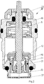
- the insert 18 is separate in the Figures 2 and 3 shown in variants.
- the parts 12, 13 which are movable relative to one another and which form the throttle body 14 form jacket surfaces provided with openings, the openings forming boundary surfaces 20, 23 of the adjustable flow cross section 10, which is covered by the valve seat 11 at least in partial areas.
- the width b of the flow channel cross section 10 extending radially to the axial direction of movement of the throttle body 14 is determined by means of the Operating part 9 variable position of the second part 13 can be preset.
- the height h of the variable flow channel cross section, which extends parallel to the direction of movement of the throttle body 14, can be changed by the throttle body 14 which can be moved relative to the seat 11 by means of the actuating attachment 8.
- the throttle body 14 has at least a first, rotatably attached to the spindle 6 part 12 and a second, rotatably connected to the first part 12 and rotatably connected to the seat 11, on the spindle 6 longitudinally adjustable and axially flowable part 13, wherein the second part 13 is movable in the direction of the first part 12 and away from it.
- the boundary surface 23 assigned to the first part 12 and the boundary surface 20 assigned to the second part 13 are arranged at an angle to the direction of movement of the throttle body, in particular not axially thereto and not orthogonally at right angles to it.
- variable flow cross section 10 formed by the two relatively movable parts 12, 13 has boundary surfaces 20, 23 arranged at an angle to the direction of movement of the throttle body 14, which determine the width b approximately radially to the direction of movement of the throttle body 14.
- the throttle body 14 has a sealing element 21 upstream of the adjustable flow cross section 10, which seals the throttle body 14 with respect to the seat 11.
- the throttle body 14 has a contour complementary to the seat 11, which enables a tight closure of the flow channel cross section 10 and a lower limitation of the spindle stroke.
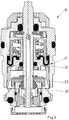
- the assembly unit (insert 18) also has, as in Figure 3 shown, a pressure control device 17, which keeps the pressure difference in the flow direction upstream and downstream of the throttle body 14 constant.
- the pressure regulating device 17 has a movable partition wall 24 (membrane) with a closure body 25 attached to it, whereby, depending on the pressure difference acting on the movable partition wall 24 of the pressures upstream in front of and downstream behind the adjustable flow cross section 10, a flow direction in series with the adjustable Flow cross section 10 arranged, formed by the closure body 25 and a seat element throttle cross section 26 can be changed in its cross-sectional area.
- the spindle 6 is equipped with a handle 22 attached to it in a rotationally fixed manner for setting the width b of the flow channel cross section 10.
- This handle 22 can be permanently installed or also be removable.
- the handle 22 can be provided with markings for the respective setting position, which correspond to markings provided in a rotationally fixed manner on the insert 18, so that the preset values can be read off.
- a compression spring 28 is provided within the assembly unit (insert 18), against which the valve spindle 6 can be displaced when actuated accordingly and which is used to reset the valve spindle 6.
- the insert 18 can be equipped with a screen 27 upstream in order to avoid contamination.
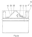
- Figure 4a the first and the second part 12, 13 of the throttle body 14 are shown in a first pre-setting of the two parts to one another, which cause a very small set flow cross-section.
- Figure 4b the first and the second part 12, 13 of the throttle body 14 are shown in a second stroke position of the two parts with respect to one another, in which the flow cross-section 10 is relatively large.
- the invention specifies a valve which enables flow rates to be preset easily, avoiding the undesirable room temperature deviations known in the prior art.
- the space requirement of the specified constructive solution is relatively small, so that an exchange of the Mounting unit, in particular also in existing housing, is possible.
Landscapes
- Engineering & Computer Science (AREA)
- General Engineering & Computer Science (AREA)
- Physics & Mathematics (AREA)
- Fluid Mechanics (AREA)
- Mechanical Engineering (AREA)
- Lift Valve (AREA)
Description
- Die Erfindung betrifft ein Ventil mit einer Einrichtung zur Voreinstellung des Strömungskanalquerschnittes für die durch das Ventil strömende Flüssigkeit für flüssigkeitsführende Heizungs- oder Kühlanlagen, bestehend aus einem ein- oder mehrteiligem Gehäuse mit mindestens einem stromaufwärts angeordnetem Einlass und mindestens einem stromabwärts angeordnetem Auslass, wobei der Einlass mit dem Auslass über einen Strömungskanal verbunden sind, und einem Anschlussstutzen, der in den Strömungskanal mündet, mit einer im Anschlussstutzen axial verschiebbar angeordneten Spindel mit aus dem Gehäuse ragendem Bedienteil und im Gehäuse angeordneten auf einen Ventilsitz wirkenden, an die Spindel gekoppelten, aus mindestens zwei relativ zueinander beweglichen Teilen bestehenden Drosselkörper, mit einer Anschlussgeometrie für einen auf die Spindel axial einwirkenden Betätigungsaufsatz sowie mit einem im Anschlussstutzen angeordneten Kopfstück und einem Ventilsitz, wobei die in dem Anschlussstutzen angeordnete Teile, nämlich mindestens Spindel, Drosselkörper, Ventilsitz und Kopfstück zu einer Montageeinheit zusammengefasst sind, die in den Anschlussstutzen als Einheit montierbar und demontierbar ist, wobei die Einzelteile unverlierbar miteinander verbunden sind.
- Aus
DE 4407447 C2 undWO 2015/010685 A2 sind Thermostatventile bekannt, die mit zwei Einrichtungen zur Begrenzung des durch das Ventil führenden Strömungskanalquerschnittes und damit zur Einstellung der Durchflussmenge ausgestattet sind. Diese Einrichtungen umfassen einerseits eine erste, voreinstellbare Drosselstelle, die den durch das Ventil führenden Strömungskanalquerschnitt dauerhaft begrenzt und andererseits eine zweite, hubabhängige Drosselstelle, die den Strömungskanalquerschnitt in Abhängigkeit von einer Regelgröße (z.B. der Raumtemperatur) durch einen seine Lage relativ zum Ventilsitz veränderbarem Ventilverschlussstück verändert. - Diese beiden in Reihe geschalteten Drosselstellen führen zu einem unvorteilhaftem Durchflussverhalten des Thermostatventils, da bei kleinen Voreinstellungen und damit kleinen Strömungskanalquerschnitten der ersten Drosselstelle die Regelung der Durchflussmenge durch die zweite Drosselstelle schon ab einem kleinen Ventilhub den Strömungskanalquerschnitt der ersten Drosselstelle übersteigt und damit wirkungslos wird.
- Dies führt zu einem unerwünschten Zweipunktverhalten, bei der die zweite Drosselstelle ständig zwischen Nulldurchfluss und der maximalen, durch die Voreinstellung der ersten Drosselstelle bestimmte Durchflussmenge wechselt. Dies hat eine unerwünscht schwankende Raumtemperatur und damit einen erhöhten Energieverbrauch zur Folge. Weiterhin ist hierbei die Ventilautorität der zweiten Drosselstelle unerwünscht niedrig, was zu einer weiteren Verschlechterung der Regelgüte führt.
- Bei großem Voreinstellwert der ersten Drosselstelle ist wiederum ein großer Ventilhub der zweiten Drosselstellung erforderlich, um den voreingestellten Strömungskanalquerschnitt der ersten Drosselstelle und damit die voreingestellte Durchflussmenge zu erreichen. Dieser unterscheidet sich wesentlich von dem wirksamen Ventilhub bei kleiner Voreinstellung.
- Nachteilig bei diesen Ausführungen sind die zwei in Reihe geschalteten Drosselstellen, da in Abhängigkeit von der Voreinstellung der ersten Drosselstelle unterschiedlich große Hübe der zweiten Drosselstelle erforderlich sind, um die gewünschten, voreingestellten Durchflüsse zu erreichen. Die üblicherweise zur Raumtemperaturregelung mit den Thermostatventilen zusammenarbeitenden Raumthermostaten ändern ihre Hubstellung und damit auch die Hubstellung des Ventils raumtemperaturabhängig, so dass bei kleinen Voreinstellungen der Solldurchfluss schon bei kleinsten Raumtemperaturänderungen und bei großen Voreinstellungen nur bei großen Raumtemperaturänderungen von mehreren Grad Kelvin erreicht wird. Dies führt zu unerwünschten Raumtemperaturabweichungen.
- In dem in
WO 2015/010685 A2 beschriebenen Thermostatventil ist zusätzlich zu der ersten und zweiten Drosselstelle eine Druckregeleinrichtung, welche die Druckdifferenz über die beiden Drosselstellen konstant hält, eingebracht. Die zuvor beschriebenen Nachteile der zwei in Reihe geschalteten Drosselstellen bestehen auch bei dieser Ventilausführung. - Aus
EP 2338093 B1 ist ein Steuerventil bekannt, bei der die erste, voreinstellbare und die zweite, hubabhängige Drosselstelle zu einer aus zwei axial zueinander fixierten aber gegeneinander verdrehbaren, mit einem Sitz zusammenwirkenden Zylinderhalbschalen gebildete Drosselstelle zusammengefasst sind und bei dem die Druckdifferenz über die Drosselstelle mittels einer Druckregeleinrichtung konstant gehalten wird. Nachteilig bei dieser Ausführung ist der große Platzbedarf dieser Konstruktion, die somit nicht in vorhandene Thermostatventilanschlussstutzen eingebracht werden kann, und dass die in dem Anschlussstutzen angeordneten Bauteile, insbesondere die aus Sitz und zwei Zylinderhalbschalen bestehende Drosselstelle, Spindel, Druckregeleinrichtung und Kopfstück nicht zu einer auswechselbaren Montageeinheit zusammengefasst sind und somit auch nicht als eine Einheit ausgetauscht werden kann. - Aus
EP 0751448 B1 ist ein Durchflussregelventil bekannt, bei dem die erste, voreinstellbare und die zweite, hubabhängige Drosselstelle zu einer Drosselstelle zusammengefasst sind und bei dem die Druckdifferenz über die Drosselstelle mittels einer Druckregeleinrichtung konstant gehalten wird, wobei die Druckregeleinrichtung gegenüberliegend zur voreinstellbaren Drosselstelle in das Gehäuse eingebracht ist. - Nachteilig bei dieser Ausführung ist ebenfalls der große Platzbedarf dieser Konstruktion und dass die in den Anschlussstutzen angeordneten Bauteile, insbesondere die aus Sitz und Kegel bestehende Drosselstelle, Spindel, Druckregeleinrichtung und Kopfstück nicht zu einer auswechselbaren Montageeinheit zusammengefasst sind und somit auch nicht als eine Einheit ausgetauscht werden können.
- Da Thermostatventile in der Regel aus einem Gehäuse bestehen, mit dem der Hersteller durch Einschrauben unterschiedlich aufgebauter Ventileinsätze unterschiedliche Ventilbaureihen aufbauen kann, sind die Innenkonturen des Anschlussstutzens, in den die Ventileinsätze eingeschraubt werden können, bei den jeweiligen Herstellern gleich ausgeführt. Dies ermöglicht den Herstellern eine kostengünstige Fertigung der Ventilbaureihen unter Verwendung immer gleicher Gehäuse.
- Auch für den Anwender ist dies vorteilhaft, da es ihm erlaubt, auch nachträglich durch Austausch der Ventileinsätze auf sich ändernde Bedingungen in der Heizungsanlagen zu reagieren und bei Ventildefekten durch Austausch der Ventileinsätze eine Reparatur des Ventils herbeizuführen. Dies ist mittels handelsüblicher Montageschleusen auch unter Anlagendruck möglich. Hierdurch wird bei Bestandanlagen mit geringem Aufwand ein Austausch der Ventileinsätze ermöglicht.
- Ausgehend von dem Stand der Technik liegen der Erfindung die Aufgaben zugrunde, einen als Montageeinheit ausgeführten Ventileinsatz zu schaffen, der mindestens Spindel, Drosselkörper, Sitz und Kopfstück umfasst und in marktübliche Thermostatventilgehäuse eingebracht werden kann, der mit einer Einrichtung zur Voreinstellung des Strömungskanalquerschnittes für die durch das Ventil strömende Flüssigkeit und einer diese überlagernde, hubabhängige Einrichtung zur Änderung des Strömungskanalquerschnittes ausgestattet ist, wobei es bei allen Voreinstellungen der ersten Einrichtung eines gleich großen Ventilhubs der zweiten Einrichtung bedarf, um die voreingestellte Durchflussmenge durch das Ventil strömen zu lassen und somit eine proportionale Regelung des Durchflusses bei allen Voreinstellungen zu ermöglichen und die voreingestellten Durchflusswerte unabhängig von der Voreinstellung bei gleicher Hubgröße zu erreichen. Die Montageeinheit soll bei Bedarf auch eine Druckregeleinrichtung, die den Druck über die Drosselstellen der ersten und zweiten Einrichtung konstant hält, umfassen. Durch Nutzung vorhandener Gehäuse soll auf kostengünstig zu fertigende Thermostatventilbaureihen aufgebaut werden.
- Zur Lösung der Aufgabe schlägt die Erfindung vor, dass die den Drosselkörper bildenden, relativ zueinander beweglichen Teile mit Durchbrüchen versehene Mantelflächen ausbilden, wobei die Durchbrüche Begrenzungsflächen des verstellbaren Strömungsquerschnittes bilden und dieser mindestens in Teilbereichen von dem Ventilsitz abgedeckt ist, und dass die sich radial zur axialen Bewegungsrichtung des Drosselkörpers erstreckende Breite des Strömungskanalquerschnitts durch die mittels des Bedienteils veränderbare Position des zweiten Teils voreingestellt ist, und dass die parallel zur Bewegungsrichtung des Drosselkörpers sich erstreckende Höhe des veränderbaren Strömungskanalquerschnittes durch den mittels des Betätigungsaufsatzes relativ zum Sitz bewegten Drosselkörpers veränderbar ist.
- Gemäß der Erfindung wird ein kostengünstig zu fertigendes Ventil, insbesondere Thermostatventil, zur Verfügung gestellt, welches aus einem Gehäuse und einem darin eingebrachten Ventileinsatz besteht, wobei der Ventileinsatz einen voreinstellbaren Strömungsquerschnitt beinhaltet und wobei dieser im Wesentlichen aus einem Sitz und einem Drosselkörper besteht, wobei die Voreinstellung die radial zur Bewegungsrichtung des Drosselkörpers erstreckende Breite des Strömungskanalquerschnitts verändert und wobei die axial zur Bewegungsrichtung des Drosselkörpers erstreckende Höhe des veränderbaren Strömungskanalquerschnittes durch die Hubbewegung des Drosselkörpers verändert wird und der Ventileinsatz als eine Montageeinheit ausgeführt ist, die in ihrer Gesamtheit in vorhandene Thermostatventilgehäuse montierbar oder demontierbar ist und mindestens einen voreinstellbaren Strömungsquerschnitt und mindestens Spindel, Drosselkörper, Sitz, Kopfstück und bei Bedarf eine Druckregeleinrichtung umfasst.
- Die Einrichtung zur Voreinstellung des Strömungskanalquerschnittes des Ventils besteht aus mindestens dem Sitz und einem aus mindestens zwei Teilen bestehenden Drosselkörper, wobei die Breite des voreinstellbaren Strömungskanalquerschnittes durch ein Bedienteil einstellbar ist und die Höhe durch die Relativbewegung des Drosselkörpers zum Sitz veränderbar ist, wobei bei Bedarf eine Druckregeleinrichtung vorgesehen ist.
- Hierzu ist insbesondere vorgesehen, dass der Drosselkörper mindestens aus einem ersten an der Spindel drehbar befestigtem Teil und einem zweiten, verdrehsicher mit dem ersten Teil und verdrehsicher mit dem Sitz verbundenen, auf der Spindel längs verstellbaren und axial durchströmbaren Teil besteht, wobei das zweite Teil in Richtung auf das erste Teil und von diesem weg beweglich ist.
- Bevorzugt ist dabei vorgesehen, dass zur Bildung der Breite des Strömungsquerschnittes bei den sich relativ zueinander beweglichen Teile die dem ersten Teil zugeordnete Begrenzungsfläche und die dem zweiten Teil zugeordnete Begrenzungsfläche im Winkel zur Bewegungsrichtung des Drosselkörpers angeordnet sind.
- Auch ist bevorzugt vorgesehen, dass der von den beiden relativ zueinander beweglichen Teile ausgebildete, veränderbare Strömungsquerschnitt im Winkel zur Bewegungsrichtung des Drosselkörpers angeordnete Begrenzungsflächen aufweist, die radial zur Bewegungsrichtung des Drosselkörpers seine Breite bestimmen.
- Zudem ist vorgesehen, dass der Drosselkörper stromaufwärts vom verstellbaren Strömungsquerschnitt ein Dichtelement aufweist, das den Drosselkörper gegenüber dem Sitz abdichtet.
- Vorteilhaft ist auch, dass der Drosselkörper eine mit dem Sitz formschlüssige Kontur aufweist, die einen dichten Verschluss des Strömungskanalquerschnittes und eine untere Begrenzung des Spindelhubs ermöglicht.
- Zusätzlich kann vorgesehen sein, dass die Montageeinheit eine Druckregeleinrichtung, welche die Druckdifferenz in Strömungsrichtung vor und hinter dem Drosselkörpers konstant hält, umfasst.
- Hierbei ist bevorzugt vorgesehen, dass die Druckregeleinrichtung eine bewegliche Trennwand mit daran angebrachtem Verschlusskörper aufweist und dass in Abhängigkeit von der auf die bewegliche Trennwand einwirkenden Druckdifferenz der stromaufwärts vor und stromabwärts hinter dem verstellbaren Strömungsquerschnitt anliegenden Drücke ein in Strömungsrichtung in Reihe mit dem verstellbaren Strömungsquerschnitt angeordneter, durch den Verschlusskörper und ein Sitzelement gebildeter Drosselquerschnitt in seiner Querschnittsfläche veränderbar ist.
- Um die Bedienung zu erleichtern ist vorgesehen, dass die Spindel mit einer drehfest an ihr angebrachten Handhabe zur Einstellung der Breite des Strömungskanalquerschnittes versehen ist.
- Hierbei ist vorgesehen, dass die Handhabe abnehmbar ist.
- Auch kann vorgesehen sein, dass die Handhabe mit Kennungen für die Einstellposition versehen ist, die mit einer drehfest an dem Ventileinsatz befestigten Kennung korrespondiert, so dass die Voreinstellwerte ablesbar sind.
- In an sich bekannter Weise ist vorgesehen, dass innerhalb der Montageeinheit eine Druckfeder angeordnet ist, die auf die Ventilspindel einwirkt.
- Zudem kann vorgesehen sein, die Montageeinheit stromaufwärts mit einem Sieb versehen ist.
- Bevorzugt ist zudem vorgesehen, dass der Winkel der Begrenzungsflächen zueinander gleich ist und zwischen einem Winkel von 90° zur Spindellängsachse und 0° dazu liegt, vorzugsweise in einem Bereich zwischen 60° und 30°.
- Ein Ausführungsbeispiel der Erfindung ist in der Zeichnung dargestellt und im Folgenden näher beschrieben.
- Es zeigt:
- Fig. 1
- ein komplettes Ventil im Zusammenbau in Ansicht, teilweise geschnitten;
- Fig. 2
- die Montageeinheit des Ventils in Ansicht im Schnitt gesehen;
- Fig. 3
- eine Variante des Einsatzes mit Druckregeleinrichtung ebenfalls im Schnitt gesehen;
- Fig. 4a
- eine Einzelheit in Ansicht in einer ersten Betriebsstellung;
- Fig. 4B
- die Einzelheit in einer zweiten Betriebsstellung;
- Fig. 5
- Einzelheiten in einer Betriebsstellung in Ansicht;
- Fig. 6
- Einzelheiten in einer Explosionsstellung in Ansicht.
- In den Zeichnungen ist ein Ventil 1 mit einer Einrichtung zur Voreinstellung des Strömungskanalquerschnittes für durch das Ventil strömende Flüssigkeiten für flüssigkeitsführende Heizungs- oder Kühlanlagen gezeigt. Es besteht aus einem ein- oder mehrteiligem Gehäuse 2 mit mindestens einem stromaufwärts angeordneten Einlass 3 und mindestens einem stromabwärts angeordneten Auslass 4. Der Einlass 3 ist mit dem Auslass 4 über einen Strömungskanal verbunden. Ein Anschlussstutzen 5 ist zwischen Einlass 3 und Auslass 4 vorgesehen, der in den Strömungskanal einmündet. Im Anschlussstutzen 5 ist axial verschiebbar eine Spindel 6 angeordnet, die ein aus dem Gehäuse 2 ragendes Bedienteil 9 aufweist, wobei im Gehäuse ein auf einen Ventilsitz 11 wirkender, mit der Spindel 6 gekoppelter, aus mindestens zwei relativ zueinander beweglichen Teilen 12, 13 bestehender Drosselkörper 14 vorgesehen ist, der eine Anschlussgeometrie 7 für einen auf die Spindel 6 axial einwirkenden Betätigungsaufsatz 8 aufweist, sowie mit einem im Anschlussstutzen 5 angeordneten Kopfstück 19 und einem Ventilsitz 11 ausgestattet ist.
- Die in dem Anschlussstutzen 5 angeordneten Teile, nämlich mindestens die Spindel 6, der Drosselkörper 14, der Ventilsitz 11 und das Kopfstück 19 sind zu einer Montageeinheit (Einsatz 18) zusammengefasst, die in den Anschlussstutzen 5 als Einheit montierbar und demontierbar ist, wobei vorzugsweise die Einzelteile unverlierbar miteinander verbunden sind. In der
Figur 1 ist gezeigt, wie der Einsatz 18 im Gehäuse 2 angeordnet ist. Der Einsatz 18 ist separat in denFiguren 2 und3 in Varianten gezeigt. - Die den Drosselkörper 14 bildenden relativ zueinander beweglichen Teile 12, 13 bilden mit Durchbrüchen versehene Mantelflächen aus, wobei die Durchbrüche Begrenzungsflächen 20, 23 des verstellbaren Strömungsquerschnittes 10 bilden, der mindestens in Teilbereichen von dem Ventilsitz 11 abgedeckt ist. Die sich radial zur axialen Bewegungsrichtung des Drosselkörpers 14 erstreckende Breite b des Strömungskanalquerschnittes 10 ist durch mittels des Bedienteils 9 veränderbare Position des zweiten Teils 13 voreinstellbar. Die parallel zur Bewegungsrichtung des Drosselkörpers 14 sich erstreckende Höhe h des veränderbaren Strömungskanalquerschnittes ist durch den mittels des Betätigungsaufsatzes 8 relativ zum Sitz 11 bewegbaren Drosselkörper 14 veränderbar.
- Wie insbesondere in
Figur 4a undFigur 4b gezeigt, weist der Drosselkörper 14 mindestens ein erstes, an der Spindel 6 drehbar befestigtes Teil 12 und ein zweites, verdrehsicher mit dem ersten Teil 12 und verdrehsicher mit dem Sitz 11 verbundenes, auf der Spindel 6 längsverstellbares und axial durchströmbares Teil 13 auf, wobei das zweite Teil 13 in Richtung auf das erste Teil 12 und von diesem weg beweglich ist. - Zur Einstellung der Breite b des Strömungsquerschnittes 10 sind bei den sich relativ zueinander beweglichen Teilen 12, 13 die dem ersten Teil 12 zugeordnete Begrenzungsfläche 23 und die dem zweiten Teil 13 zugeordnete Begrenzungsfläche 20 in einem Winkel zur Bewegungsrichtung des Drosselkörpers angeordnet, insbesondere nicht axial dazu und nicht orthogonal rechtwinklig dazu.
- Der von den beiden relativ zueinander beweglichen Teilen 12, 13 ausgebildete, veränderbare Strömungsquerschnitt 10 weist im Winkel zu der Bewegungsrichtung des Drosselkörpers 14 angeordnete Begrenzungsflächen 20, 23 auf, die etwa radial zur Bewegungsrichtung des Drosselkörpers 14 die Breite b bestimmen.
- Der Drosselkörper 14 weist stromaufwärts vom verstellbaren Strömungsquerschnitt 10 ein Dichtelement 21 auf, welches den Drosselkörper 14 gegenüber dem Sitz 11 abdichtet. Der Drosselkörper 14 weist eine mit dem Sitz 11 komplementäre Kontur auf, die einen dichten Verschluss des Strömungskanalquerschnittes 10 und eine untere Begrenzung des Spindelhubs ermöglicht.
- Die Montageeinheit (Einsatz 18) weist zudem, wie in
Figur 3 gezeigt, eine Druckregeleinrichtung 17 auf, welche die Druckdifferenz in Strömungsrichtung vor und hinter dem Drosselkörper 14 konstant hält. Die Druckregeleinrichtung 17 weist eine bewegliche Trennwand 24 (Membran) mit daran angebrachtem Verschlusskörper 25 auf, wobei in Abhängigkeit von der auf die bewegliche Trennwand 24 einwirkenden Druckdifferenz der stromaufwärts vor und stromabwärts hinter dem verstellbaren Strömungsquerschnitt 10 anliegenden Drücke ein in Strömungsrichtung in Reihe mit dem verstellbaren Strömungsquerschnitt 10 angeordneter, durch den Verschlusskörper 25 und ein Sitzelement gebildeter Drosselquerschnitt 26 in seiner Querschnittsfläche veränderbar ist. - Wie insbesondere in
Figur 1 gezeigt, ist die Spindel 6 mit einer drehfest an ihr angebrachten Handhabe 22 zur Einstellung der Breite b des Strömungskanalquerschnittes 10 ausgestattet. Diese Handhabe 22 kann fest installiert sein oder auch abnehmbar sein. Zusätzlich kann die Handhabe 22 mit Kennzeichnungen für die jeweilige Einstellposition versehen sein, die mit drehfest an dem Einsatz 18 vorgesehenen Markierungen korrespondiert, sodass die Voreinstellwerte abgelesen werden können. - In an sich bekannter Weise ist innerhalb der Montageeinheit (Einsatz 18) eine Druckfeder 28 vorgesehen, gegen welche die Ventilspindel 6 bei entsprechender Betätigung verschoben werden kann und die zur Rückstellung der Ventilspindel 6 benutzt wird.
- Zusätzlich kann der Einsatz 18 stromaufwärts mit einem Sieb 27 ausgestattet sein, um Verunreinigungen zu vermeiden.
- In
Figur 4a sind das erste und das zweite Teil 12, 13 des Drosselkörpers 14 in einer ersten Voreinstellung der beiden Teile zueinander gezeigt, die einen sehr kleinen eingestellten Strömungsquerschnitt bewirken. InFigur 4b ist das erste und das zweite Teil 12, 13 des Drosselkörpers 14 in einer zweiten Hubstellung der beiden Teile zueinander gezeigt, bei welcher der Strömungsquerschnitt 10 relativ groß ist. - Durch entsprechende Vorsprünge des zweiten Teiles 13 und dazu passende Ausnehmungen des ersten Teiles 12 sind die Teile zueinander geführt und relativ zueinander unverdrehbar gehalten. Die Vorsprünge und Ausnehmungen sind in den
Figuren 4 bis 6 gut ersichtlich. - Die Erfindung gibt ein Ventil an, welches eine einfache Voreinstellung von Durchflüssen ermöglicht, wobei die im Stand der Technik bekannten unerwünschten Raumtemperaturabweichungen vermieden werden. Zudem ist der Platzbedarf der angegebenen konstruktiven Lösung relativ gering, sodass ein Austausch der Montageeinheit, insbesondere auch in bestehende Gehäuse möglich ist.
- Die Erfindung ist nicht auf die Ausführungsbeispiele beschränkt, sondern im Rahmen der Offenbarung vielfach variabel.
- Alle neuen in der Beschreibung und/oder Zeichnung offenbarten Einzel- und Kombinationsmerkmale werden als erfindungswesentlich angesehen.
-
- 1
- Ventil
- 2
- Gehäuse
- 3
- Einlass
- 4
- Auslass
- 5
- Anschlussstutzen
- 6
- Spindel
- 7
- Anschlussgeometrie
- 8
- Betätigungsaufsatz
- 9
- Bedienteil
- 10
- Strömungsquerschnitt
- 11
- Ventilsitz
- 12
- erstes Teil
- 13
- zweites Teil
- 14
- Drosselkörper
- 15
- Dichtung
- 16
- Kontur
- 17
- Druckregeleinrichtung
- 18
- (Montageeinheit) Einsatz
- 19
- Kopfstück
- 20
- Begrenzungsfläche von 13
- 21
- Dichtelement
- 22
- Handhabe
- 23
- Begrenzungsfläche von 12
- 24
- Trennwand von 17
- 25
- Verschlusskörper
- 26
- Drosselquerschnitt
- 27
- Sieb
- 28
- Druckfeder
- b
- Breite von 10
- h
- Höhe von 10
Claims (14)
- Ventil (1) mit einer Einrichtung zur Voreinstellung des Strömungskanalquerschnittes für die durch das Ventil (1) strömende Flüssigkeit für flüssigkeitsführende Heizungs- oder Kühlanlagen, bestehend aus einem ein- oder mehrteiligem Gehäuse (2) mit mindestens einem stromaufwärts angeordnetem Einlass (3) und mindestens einem stromabwärts angeordnetem Auslass (4), wobei der Einlass (3) mit dem Auslass (4) über einen Strömungskanal verbunden sind, und einem Anschlussstutzen (5), der in den Strömungskanal mündet, mit einer im Anschlussstutzen (5) axial verschiebbar angeordneten Spindel (6) mit aus dem Gehäuse (2) ragendem Bedienteil (9) und im Gehäuse (2) angeordneten auf einen Ventilsitz (11) wirkenden, an die Spindel (6) gekoppelten, aus mindestens zwei relativ zueinander beweglichen Teilen (12, 13) bestehenden Drosselkörper (14), mit einer Anschlussgeometrie (7) für einen auf die Spindel (6) axial einwirkenden Betätigungsaufsatz (8) sowie mit einem im Anschlussstutzen (5) angeordneten Kopfstück (19) und dem Ventilsitz (11), wobei die in dem Anschlussstutzen (5) angeordneten Teile, nämlich mindestens Spindel (6), Drosselkörper (14), Ventilsitz (11) und Kopfstück (19) zu einer Montageeinheit (18) zusammengefasst sind, die in den Anschlussstutzen (5) als Einheit montierbar und demontierbar ist, wobei die Einzelteile unverlierbar miteinander verbunden sind, dadurch gekennzeichnet, dass die den Drosselkörper (14) bildenden, relativ zueinander beweglichen Teile (12, 13) mit Durchbrüchen versehene Mantelflächen ausbilden, wobei die Durchbrüche Begrenzungsflächen (20, 23) des verstellbaren Strömungsquerschnittes (10) bilden und dieser mindestens in Teilbereichen von dem Ventilsitz (11) abgedeckt ist, und dass die sich radial zur axialen Bewegungsrichtung des Drosselkörpers (14) erstreckende Breite (b) des Strömungskanalquerschnitts (10) durch die mittels des Bedienteils (9) veränderbare Position des zweiten Teils (13) voreingestellt ist, und dass die parallel zur Bewegungsrichtung des Drosselkörpers (14) sich erstreckende Höhe (h) des veränderbaren Strömungskanalquerschnittes (10) durch den mittels des Betätigungsaufsatzes (8) relativ zum Sitz (11) bewegten Drosselkörpers (14) veränderbar ist.
- Ventil nach Anspruch 1, dadurch gekennzeichnet, dass der Drosselkörper (14) mindestens aus einem ersten an der Spindel (6) drehbar befestigtem Teil (12) und einem zweiten, verdrehsicher mit dem ersten Teil (12) und verdrehsicher mit dem Sitz (11) verbundenen, auf der Spindel (6) längs verstellbaren und axial durchströmbaren Teil (13) besteht, wobei das zweite Teil (13) in Richtung auf das erste Teil (12) und von diesem weg beweglich ist.
- Ventil nach Anspruch 1 oder 2, dadurch gekennzeichnet, dass zur Bildung der Breite (b) des Strömungsquerschnittes (10) bei den sich relativ zueinander beweglichen Teile (12,13) die dem ersten Teil (12) zugeordnete Begrenzungsfläche (23) und die dem zweiten Teil (13) zugeordnete Begrenzungsfläche (20) im Winkel zur Bewegungsrichtung des Drosselkörpers (14) angeordnet sind.
- Ventil nach einem der Ansprüche 1 bis 3, dadurch gekennzeichnet, dass der von den beiden relativ zueinander beweglichen Teile (12, 13) ausgebildete, veränderbare Strömungsquerschnitt (10) im Winkel zur Bewegungsrichtung des Drosselkörpers (14) angeordnete Begrenzungsflächen (20, 23) aufweist, die radial zur Bewegungsrichtung des Drosselkörpers (14) seine Breite (b) bestimmen.
- Ventil nach einem der Ansprüche 1 bis 4, dadurch gekennzeichnet, dass der Drosselkörper (14) stromaufwärts vom verstellbaren Strömungsquerschnitt (10) ein Dichtelement (21) aufweist, das den Drosselkörper (14) gegenüber dem Sitz (11) abdichtet.
- Ventil nach einem der Ansprüche 1 bis 5, dadurch gekennzeichnet, dass der Drosselkörper (14) eine mit dem Sitz (11) formschlüssige Kontur (16) aufweist, die einen dichten Verschluss des Strömungskanalquerschnittes (10) und eine untere Begrenzung des Spindelhubs ermöglicht.
- Ventil nach einem der Ansprüche 1 bis 6, dadurch gekennzeichnet, dass die Montageeinheit 18) eine Druckregeleinrichtung (17), welche die Druckdifferenz in Strömungsrichtung vor und hinter dem Drosselkörpers (14) konstant hält, umfasst.
- Ventil nach Anspruch 7, dadurch gekennzeichnet, dass die Druckregeleinrichtung (17) eine bewegliche Trennwand (24) mit daran angebrachtem Verschlusskörper (25) aufweist und dass in Abhängigkeit von der auf die bewegliche Trennwand (24) einwirkenden Druckdifferenz der stromaufwärts vor und stromabwärts hinter dem verstellbaren Strömungsquerschnitt (10) anliegenden Drücke ein in Strömungsrichtung in Reihe mit dem verstellbaren Strömungsquerschnitt (10) angeordneter, durch den Verschlusskörper (25) und ein Sitzelement gebildeten Drosselquerschnitt (26) in seiner Querschnittsfläche veränderbar ist.
- Ventil nach einem der Ansprüche 1 bis 8, dadurch gekennzeichnet, dass die Spindel (6) mit einer drehfest an ihr angebrachten Handhabe (22) zur Einstellung der Breite (b) des Strömungskanalquerschnittes (10) versehen ist.
- Ventil nach Anspruch 9, dadurch gekennzeichnet, dass die Handhabe (22) abnehmbar ist.
- Ventil nach Anspruch 9 oder 10, dadurch gekennzeichnet, dass die Handhabe (22) mit Kennungen für die Einstellposition versehen ist, die mit einer drehfest an der Montageeinheit (18) befestigten Kennung korrespondiert, so dass die Voreinstellwerte ablesbar sind.
- Ventil nach einem der Ansprüche 1 bis 11, dadurch gekennzeichnet, dass innerhalb der Montageeinheit eine Druckfeder (28) angeordnet ist, die auf die Ventilspindel (6) einwirkt.
- Ventil nach einem der Ansprüche 1 bis 12, dadurch gekennzeichnet, dass die Montageeinheit stromaufwärts mit einem mit einem Sieb (27) versehen ist.
- Ventil nach einem der Ansprüche 1 bis 13, dadurch gekennzeichnet, dass der Winkel der Begrenzungsflächen (20, 23) zueinander gleich ist und zwischen einem Winkel von 90° zur Spindellängsachse und 0° dazu liegt, vorzugsweise in einem Bereich zwischen 60° und 30°.
Priority Applications (3)
| Application Number | Priority Date | Filing Date | Title |
|---|---|---|---|
| PL18157399T PL3527862T3 (pl) | 2018-02-19 | 2018-02-19 | Zawór z urządzeniem do wstępnego ustawiania przekroju poprzecznego kanału przepływowego |
| EP18157399.9A EP3527862B1 (de) | 2018-02-19 | 2018-02-19 | Ventil mit einer einrichtung zur voreinstellung des strömungskanalquerschnittes |
| DK18157399.9T DK3527862T3 (da) | 2018-02-19 | 2018-02-19 | Ventil med en indretning til forudindstilling af strømningskanaltværsnittet |
Applications Claiming Priority (1)
| Application Number | Priority Date | Filing Date | Title |
|---|---|---|---|
| EP18157399.9A EP3527862B1 (de) | 2018-02-19 | 2018-02-19 | Ventil mit einer einrichtung zur voreinstellung des strömungskanalquerschnittes |
Publications (2)
| Publication Number | Publication Date |
|---|---|
| EP3527862A1 EP3527862A1 (de) | 2019-08-21 |
| EP3527862B1 true EP3527862B1 (de) | 2020-10-21 |
Family
ID=61244465
Family Applications (1)
| Application Number | Title | Priority Date | Filing Date |
|---|---|---|---|
| EP18157399.9A Active EP3527862B1 (de) | 2018-02-19 | 2018-02-19 | Ventil mit einer einrichtung zur voreinstellung des strömungskanalquerschnittes |
Country Status (3)
| Country | Link |
|---|---|
| EP (1) | EP3527862B1 (de) |
| DK (1) | DK3527862T3 (de) |
| PL (1) | PL3527862T3 (de) |
Families Citing this family (1)
| Publication number | Priority date | Publication date | Assignee | Title |
|---|---|---|---|---|
| IT201900019856A1 (it) * | 2019-10-28 | 2021-04-28 | Fugas S P A | Valvola modulante con regolazione di portata minima |
Family Cites Families (4)
| Publication number | Priority date | Publication date | Assignee | Title |
|---|---|---|---|---|
| DE4407447C2 (de) | 1994-03-07 | 1999-04-29 | Oventrop Sohn Kg F W | Voreinstellbares Regulierventil |
| DE59509096D1 (de) | 1995-06-28 | 2001-04-19 | Siemens Building Tech Ag | Durchfluss-Regelventil |
| DK177066B1 (da) | 2008-05-05 | 2011-05-23 | Frese As | Reguleringsventil |
| DK3104246T3 (da) | 2013-07-22 | 2018-01-15 | Oventrop Gmbh & Co Kg | Gennemstrømningsregulerende ventil |
-
2018
- 2018-02-19 EP EP18157399.9A patent/EP3527862B1/de active Active
- 2018-02-19 PL PL18157399T patent/PL3527862T3/pl unknown
- 2018-02-19 DK DK18157399.9T patent/DK3527862T3/da active
Non-Patent Citations (1)
| Title |
|---|
| None * |
Also Published As
| Publication number | Publication date |
|---|---|
| EP3527862A1 (de) | 2019-08-21 |
| DK3527862T3 (da) | 2021-01-25 |
| PL3527862T3 (pl) | 2021-04-19 |
Similar Documents
| Publication | Publication Date | Title |
|---|---|---|
| EP2271969B1 (de) | Armaturenkombination zur regelung der durchflussmenge oder des differenzdruckes | |
| EP3025207B1 (de) | Durchflussregelventil | |
| EP2664719B1 (de) | Sanitäres Einbauelement | |
| EP0242675B1 (de) | Mischbatterie | |
| DE102009011343B4 (de) | Durchflussmengenregler | |
| DE10084851B3 (de) | Regulierventil für konstanten Durchfluß | |
| DE60033281T2 (de) | Thermostatisches mischventil | |
| EP2988071A1 (de) | Durchflussmengenregler | |
| DE1750046A1 (de) | Einstellbares Schaltventil | |
| DE69230948T2 (de) | Einhebelmischarmatur mit einer Vorrichtung zum Vermeiden von Wasserschlägen während des Hebelschliessvorganges | |
| DE69124977T2 (de) | Durchflussregler | |
| DE8324276U1 (de) | Drosselvorrichtung | |
| EP1859329A1 (de) | Durchflussmengenregler | |
| DE102013107762A1 (de) | Durchflussregelventil | |
| DE69300578T2 (de) | Verbesserungen von thermostatischen Kappen und Mischungsventilen mit solchen Kappen. | |
| DE1813599A1 (de) | Ventile,insbesondere Haehne,mit grosser AEnderung der Durchflussmengen | |
| EP3527862A1 (de) | Ventil mit einer einrichtung zur voreinstellung des strömungskanalquerschnittes | |
| DE102007013505A1 (de) | Armaturenkombination zur Regelung der Durchflussmenge oder des Differenzdruckes | |
| DE102017102308A1 (de) | Ventil mit einer Einrichtung zur Voreinstellung des Strömungskanalquerschnittes | |
| DE2432823A1 (de) | Einstellbares stromregelventil | |
| DE102018213712B4 (de) | Ventilanordnung | |
| DE69227256T2 (de) | Mengen-und temperaturbegrenzungsvorrichtung fuer ein mischventil | |
| DE3227116C2 (de) | Druckregelventil für Flüssigkeiten | |
| DE10115641A1 (de) | Sanitäres Thermostatventil | |
| DE4409498B4 (de) | Wassermischventil |
Legal Events
| Date | Code | Title | Description |
|---|---|---|---|
| PUAI | Public reference made under article 153(3) epc to a published international application that has entered the european phase |
Free format text: ORIGINAL CODE: 0009012 |
|
| STAA | Information on the status of an ep patent application or granted ep patent |
Free format text: STATUS: THE APPLICATION HAS BEEN PUBLISHED |
|
| AK | Designated contracting states |
Kind code of ref document: A1 Designated state(s): AL AT BE BG CH CY CZ DE DK EE ES FI FR GB GR HR HU IE IS IT LI LT LU LV MC MK MT NL NO PL PT RO RS SE SI SK SM TR |
|
| AX | Request for extension of the european patent |
Extension state: BA ME |
|
| STAA | Information on the status of an ep patent application or granted ep patent |
Free format text: STATUS: REQUEST FOR EXAMINATION WAS MADE |
|
| 17P | Request for examination filed |
Effective date: 20200129 |
|
| RBV | Designated contracting states (corrected) |
Designated state(s): AL AT BE BG CH CY CZ DE DK EE ES FI FR GB GR HR HU IE IS IT LI LT LU LV MC MK MT NL NO PL PT RO RS SE SI SK SM TR |
|
| GRAP | Despatch of communication of intention to grant a patent |
Free format text: ORIGINAL CODE: EPIDOSNIGR1 |
|
| STAA | Information on the status of an ep patent application or granted ep patent |
Free format text: STATUS: GRANT OF PATENT IS INTENDED |
|
| RIC1 | Information provided on ipc code assigned before grant |
Ipc: F24D 19/10 20060101ALI20200504BHEP Ipc: G05D 7/01 20060101ALI20200504BHEP Ipc: F16K 1/52 20060101AFI20200504BHEP |
|
| INTG | Intention to grant announced |
Effective date: 20200603 |
|
| GRAS | Grant fee paid |
Free format text: ORIGINAL CODE: EPIDOSNIGR3 |
|
| GRAA | (expected) grant |
Free format text: ORIGINAL CODE: 0009210 |
|
| STAA | Information on the status of an ep patent application or granted ep patent |
Free format text: STATUS: THE PATENT HAS BEEN GRANTED |
|
| AK | Designated contracting states |
Kind code of ref document: B1 Designated state(s): AL AT BE BG CH CY CZ DE DK EE ES FI FR GB GR HR HU IE IS IT LI LT LU LV MC MK MT NL NO PL PT RO RS SE SI SK SM TR |
|
| REG | Reference to a national code |
Ref country code: GB Ref legal event code: FG4D Free format text: NOT ENGLISH |
|
| REG | Reference to a national code |
Ref country code: CH Ref legal event code: EP |
|
| REG | Reference to a national code |
Ref country code: DE Ref legal event code: R096 Ref document number: 502018002757 Country of ref document: DE |
|
| REG | Reference to a national code |
Ref country code: IE Ref legal event code: FG4D Free format text: LANGUAGE OF EP DOCUMENT: GERMAN |
|
| REG | Reference to a national code |
Ref country code: CH Ref legal event code: NV Representative=s name: TROESCH SCHEIDEGGER WERNER AG, CH |
|
| REG | Reference to a national code |
Ref country code: AT Ref legal event code: REF Ref document number: 1326166 Country of ref document: AT Kind code of ref document: T Effective date: 20201115 |
|
| REG | Reference to a national code |
Ref country code: NL Ref legal event code: FP |
|
| REG | Reference to a national code |
Ref country code: DK Ref legal event code: T3 Effective date: 20210120 |
|
| PG25 | Lapsed in a contracting state [announced via postgrant information from national office to epo] |
Ref country code: RS Free format text: LAPSE BECAUSE OF FAILURE TO SUBMIT A TRANSLATION OF THE DESCRIPTION OR TO PAY THE FEE WITHIN THE PRESCRIBED TIME-LIMIT Effective date: 20201021 Ref country code: PT Free format text: LAPSE BECAUSE OF FAILURE TO SUBMIT A TRANSLATION OF THE DESCRIPTION OR TO PAY THE FEE WITHIN THE PRESCRIBED TIME-LIMIT Effective date: 20210222 Ref country code: FI Free format text: LAPSE BECAUSE OF FAILURE TO SUBMIT A TRANSLATION OF THE DESCRIPTION OR TO PAY THE FEE WITHIN THE PRESCRIBED TIME-LIMIT Effective date: 20201021 Ref country code: NO Free format text: LAPSE BECAUSE OF FAILURE TO SUBMIT A TRANSLATION OF THE DESCRIPTION OR TO PAY THE FEE WITHIN THE PRESCRIBED TIME-LIMIT Effective date: 20210121 Ref country code: GR Free format text: LAPSE BECAUSE OF FAILURE TO SUBMIT A TRANSLATION OF THE DESCRIPTION OR TO PAY THE FEE WITHIN THE PRESCRIBED TIME-LIMIT Effective date: 20210122 |
|
| REG | Reference to a national code |
Ref country code: LT Ref legal event code: MG4D |
|
| PG25 | Lapsed in a contracting state [announced via postgrant information from national office to epo] |
Ref country code: SE Free format text: LAPSE BECAUSE OF FAILURE TO SUBMIT A TRANSLATION OF THE DESCRIPTION OR TO PAY THE FEE WITHIN THE PRESCRIBED TIME-LIMIT Effective date: 20201021 Ref country code: ES Free format text: LAPSE BECAUSE OF FAILURE TO SUBMIT A TRANSLATION OF THE DESCRIPTION OR TO PAY THE FEE WITHIN THE PRESCRIBED TIME-LIMIT Effective date: 20201021 Ref country code: BG Free format text: LAPSE BECAUSE OF FAILURE TO SUBMIT A TRANSLATION OF THE DESCRIPTION OR TO PAY THE FEE WITHIN THE PRESCRIBED TIME-LIMIT Effective date: 20210121 Ref country code: IS Free format text: LAPSE BECAUSE OF FAILURE TO SUBMIT A TRANSLATION OF THE DESCRIPTION OR TO PAY THE FEE WITHIN THE PRESCRIBED TIME-LIMIT Effective date: 20210221 Ref country code: LV Free format text: LAPSE BECAUSE OF FAILURE TO SUBMIT A TRANSLATION OF THE DESCRIPTION OR TO PAY THE FEE WITHIN THE PRESCRIBED TIME-LIMIT Effective date: 20201021 |
|
| PG25 | Lapsed in a contracting state [announced via postgrant information from national office to epo] |
Ref country code: HR Free format text: LAPSE BECAUSE OF FAILURE TO SUBMIT A TRANSLATION OF THE DESCRIPTION OR TO PAY THE FEE WITHIN THE PRESCRIBED TIME-LIMIT Effective date: 20201021 |
|
| REG | Reference to a national code |
Ref country code: DE Ref legal event code: R097 Ref document number: 502018002757 Country of ref document: DE |
|
| PG25 | Lapsed in a contracting state [announced via postgrant information from national office to epo] |
Ref country code: SM Free format text: LAPSE BECAUSE OF FAILURE TO SUBMIT A TRANSLATION OF THE DESCRIPTION OR TO PAY THE FEE WITHIN THE PRESCRIBED TIME-LIMIT Effective date: 20201021 Ref country code: CZ Free format text: LAPSE BECAUSE OF FAILURE TO SUBMIT A TRANSLATION OF THE DESCRIPTION OR TO PAY THE FEE WITHIN THE PRESCRIBED TIME-LIMIT Effective date: 20201021 Ref country code: EE Free format text: LAPSE BECAUSE OF FAILURE TO SUBMIT A TRANSLATION OF THE DESCRIPTION OR TO PAY THE FEE WITHIN THE PRESCRIBED TIME-LIMIT Effective date: 20201021 Ref country code: LT Free format text: LAPSE BECAUSE OF FAILURE TO SUBMIT A TRANSLATION OF THE DESCRIPTION OR TO PAY THE FEE WITHIN THE PRESCRIBED TIME-LIMIT Effective date: 20201021 Ref country code: RO Free format text: LAPSE BECAUSE OF FAILURE TO SUBMIT A TRANSLATION OF THE DESCRIPTION OR TO PAY THE FEE WITHIN THE PRESCRIBED TIME-LIMIT Effective date: 20201021 Ref country code: SK Free format text: LAPSE BECAUSE OF FAILURE TO SUBMIT A TRANSLATION OF THE DESCRIPTION OR TO PAY THE FEE WITHIN THE PRESCRIBED TIME-LIMIT Effective date: 20201021 |
|
| PLBE | No opposition filed within time limit |
Free format text: ORIGINAL CODE: 0009261 |
|
| STAA | Information on the status of an ep patent application or granted ep patent |
Free format text: STATUS: NO OPPOSITION FILED WITHIN TIME LIMIT |
|
| REG | Reference to a national code |
Ref country code: DE Ref legal event code: R119 Ref document number: 502018002757 Country of ref document: DE |
|
| 26N | No opposition filed |
Effective date: 20210722 |
|
| PG25 | Lapsed in a contracting state [announced via postgrant information from national office to epo] |
Ref country code: MC Free format text: LAPSE BECAUSE OF FAILURE TO SUBMIT A TRANSLATION OF THE DESCRIPTION OR TO PAY THE FEE WITHIN THE PRESCRIBED TIME-LIMIT Effective date: 20201021 |
|
| PG25 | Lapsed in a contracting state [announced via postgrant information from national office to epo] |
Ref country code: LU Free format text: LAPSE BECAUSE OF NON-PAYMENT OF DUE FEES Effective date: 20210219 Ref country code: IT Free format text: LAPSE BECAUSE OF FAILURE TO SUBMIT A TRANSLATION OF THE DESCRIPTION OR TO PAY THE FEE WITHIN THE PRESCRIBED TIME-LIMIT Effective date: 20201021 Ref country code: AL Free format text: LAPSE BECAUSE OF FAILURE TO SUBMIT A TRANSLATION OF THE DESCRIPTION OR TO PAY THE FEE WITHIN THE PRESCRIBED TIME-LIMIT Effective date: 20201021 |
|
| PG25 | Lapsed in a contracting state [announced via postgrant information from national office to epo] |
Ref country code: SI Free format text: LAPSE BECAUSE OF FAILURE TO SUBMIT A TRANSLATION OF THE DESCRIPTION OR TO PAY THE FEE WITHIN THE PRESCRIBED TIME-LIMIT Effective date: 20201021 |
|
| PG25 | Lapsed in a contracting state [announced via postgrant information from national office to epo] |
Ref country code: DE Free format text: LAPSE BECAUSE OF NON-PAYMENT OF DUE FEES Effective date: 20210901 Ref country code: IE Free format text: LAPSE BECAUSE OF NON-PAYMENT OF DUE FEES Effective date: 20210219 |
|
| PG25 | Lapsed in a contracting state [announced via postgrant information from national office to epo] |
Ref country code: IS Free format text: LAPSE BECAUSE OF FAILURE TO SUBMIT A TRANSLATION OF THE DESCRIPTION OR TO PAY THE FEE WITHIN THE PRESCRIBED TIME-LIMIT Effective date: 20210221 |
|
| P01 | Opt-out of the competence of the unified patent court (upc) registered |
Effective date: 20230510 |
|
| PG25 | Lapsed in a contracting state [announced via postgrant information from national office to epo] |
Ref country code: CY Free format text: LAPSE BECAUSE OF FAILURE TO SUBMIT A TRANSLATION OF THE DESCRIPTION OR TO PAY THE FEE WITHIN THE PRESCRIBED TIME-LIMIT Effective date: 20201021 |
|
| PG25 | Lapsed in a contracting state [announced via postgrant information from national office to epo] |
Ref country code: HU Free format text: LAPSE BECAUSE OF FAILURE TO SUBMIT A TRANSLATION OF THE DESCRIPTION OR TO PAY THE FEE WITHIN THE PRESCRIBED TIME-LIMIT; INVALID AB INITIO Effective date: 20180219 |
|
| PG25 | Lapsed in a contracting state [announced via postgrant information from national office to epo] |
Ref country code: MK Free format text: LAPSE BECAUSE OF FAILURE TO SUBMIT A TRANSLATION OF THE DESCRIPTION OR TO PAY THE FEE WITHIN THE PRESCRIBED TIME-LIMIT Effective date: 20201021 |
|
| PG25 | Lapsed in a contracting state [announced via postgrant information from national office to epo] |
Ref country code: MT Free format text: LAPSE BECAUSE OF FAILURE TO SUBMIT A TRANSLATION OF THE DESCRIPTION OR TO PAY THE FEE WITHIN THE PRESCRIBED TIME-LIMIT Effective date: 20201021 |
|
| PGFP | Annual fee paid to national office [announced via postgrant information from national office to epo] |
Ref country code: NL Payment date: 20250220 Year of fee payment: 8 |
|
| PGFP | Annual fee paid to national office [announced via postgrant information from national office to epo] |
Ref country code: DK Payment date: 20250218 Year of fee payment: 8 |
|
| PGFP | Annual fee paid to national office [announced via postgrant information from national office to epo] |
Ref country code: AT Payment date: 20250220 Year of fee payment: 8 Ref country code: CH Payment date: 20250305 Year of fee payment: 8 Ref country code: BE Payment date: 20250218 Year of fee payment: 8 |
|
| PGFP | Annual fee paid to national office [announced via postgrant information from national office to epo] |
Ref country code: FR Payment date: 20250221 Year of fee payment: 8 Ref country code: PL Payment date: 20250204 Year of fee payment: 8 |
|
| PGFP | Annual fee paid to national office [announced via postgrant information from national office to epo] |
Ref country code: GB Payment date: 20250227 Year of fee payment: 8 |
|
| PG25 | Lapsed in a contracting state [announced via postgrant information from national office to epo] |
Ref country code: TR Free format text: LAPSE BECAUSE OF FAILURE TO SUBMIT A TRANSLATION OF THE DESCRIPTION OR TO PAY THE FEE WITHIN THE PRESCRIBED TIME-LIMIT Effective date: 20201021 |