EP3527954A1 - Türsensor mit drehwinkelgeber - Google Patents
Türsensor mit drehwinkelgeber Download PDFInfo
- Publication number
- EP3527954A1 EP3527954A1 EP18157281.9A EP18157281A EP3527954A1 EP 3527954 A1 EP3527954 A1 EP 3527954A1 EP 18157281 A EP18157281 A EP 18157281A EP 3527954 A1 EP3527954 A1 EP 3527954A1
- Authority
- EP
- European Patent Office
- Prior art keywords
- door
- rotary encoder
- sensor
- door leaf
- leaf
- Prior art date
- Legal status (The legal status is an assumption and is not a legal conclusion. Google has not performed a legal analysis and makes no representation as to the accuracy of the status listed.)
- Granted
Links
Images


Classifications
-
- G—PHYSICS
- G01—MEASURING; TESTING
- G01D—MEASURING NOT SPECIALLY ADAPTED FOR A SPECIFIC VARIABLE; ARRANGEMENTS FOR MEASURING TWO OR MORE VARIABLES NOT COVERED IN A SINGLE OTHER SUBCLASS; TARIFF METERING APPARATUS; MEASURING OR TESTING NOT OTHERWISE PROVIDED FOR
- G01D11/00—Component parts of measuring arrangements not specially adapted for a specific variable
- G01D11/30—Supports specially adapted for an instrument; Supports specially adapted for a set of instruments
-
- E—FIXED CONSTRUCTIONS
- E05—LOCKS; KEYS; WINDOW OR DOOR FITTINGS; SAFES
- E05F—DEVICES FOR MOVING WINGS INTO OPEN OR CLOSED POSITION; CHECKS FOR WINGS; WING FITTINGS NOT OTHERWISE PROVIDED FOR, CONCERNED WITH THE FUNCTIONING OF THE WING
- E05F7/00—Accessories for wings not provided for in other groups of this subclass
-
- E—FIXED CONSTRUCTIONS
- E05—LOCKS; KEYS; WINDOW OR DOOR FITTINGS; SAFES
- E05F—DEVICES FOR MOVING WINGS INTO OPEN OR CLOSED POSITION; CHECKS FOR WINGS; WING FITTINGS NOT OTHERWISE PROVIDED FOR, CONCERNED WITH THE FUNCTIONING OF THE WING
- E05F15/00—Power-operated mechanisms for wings
- E05F15/40—Safety devices, e.g. detection of obstructions or end positions
- E05F15/42—Detection using safety edges
- E05F15/43—Detection using safety edges responsive to disruption of energy beams, e.g. light or sound
-
- G—PHYSICS
- G01—MEASURING; TESTING
- G01C—MEASURING DISTANCES, LEVELS OR BEARINGS; SURVEYING; NAVIGATION; GYROSCOPIC INSTRUMENTS; PHOTOGRAMMETRY OR VIDEOGRAMMETRY
- G01C1/00—Measuring angles
-
- G—PHYSICS
- G01—MEASURING; TESTING
- G01C—MEASURING DISTANCES, LEVELS OR BEARINGS; SURVEYING; NAVIGATION; GYROSCOPIC INSTRUMENTS; PHOTOGRAMMETRY OR VIDEOGRAMMETRY
- G01C19/00—Gyroscopes; Turn-sensitive devices using vibrating masses; Turn-sensitive devices without moving masses; Measuring angular rate using gyroscopic effects
-
- G—PHYSICS
- G01—MEASURING; TESTING
- G01C—MEASURING DISTANCES, LEVELS OR BEARINGS; SURVEYING; NAVIGATION; GYROSCOPIC INSTRUMENTS; PHOTOGRAMMETRY OR VIDEOGRAMMETRY
- G01C19/00—Gyroscopes; Turn-sensitive devices using vibrating masses; Turn-sensitive devices without moving masses; Measuring angular rate using gyroscopic effects
- G01C19/56—Turn-sensitive devices using vibrating masses, e.g. vibratory angular rate sensors based on Coriolis forces
- G01C19/5776—Signal processing not specific to any of the devices covered by groups G01C19/5607 - G01C19/5719
-
- H—ELECTRICITY
- H04—ELECTRIC COMMUNICATION TECHNIQUE
- H04N—PICTORIAL COMMUNICATION, e.g. TELEVISION
- H04N23/00—Cameras or camera modules comprising electronic image sensors; Control thereof
- H04N23/50—Constructional details
- H04N23/54—Mounting of pick-up tubes, electronic image sensors, deviation or focusing coils
-
- H—ELECTRICITY
- H04—ELECTRIC COMMUNICATION TECHNIQUE
- H04N—PICTORIAL COMMUNICATION, e.g. TELEVISION
- H04N7/00—Television systems
- H04N7/18—Closed-circuit television [CCTV] systems, i.e. systems in which the video signal is not broadcast
-
- E—FIXED CONSTRUCTIONS
- E05—LOCKS; KEYS; WINDOW OR DOOR FITTINGS; SAFES
- E05F—DEVICES FOR MOVING WINGS INTO OPEN OR CLOSED POSITION; CHECKS FOR WINGS; WING FITTINGS NOT OTHERWISE PROVIDED FOR, CONCERNED WITH THE FUNCTIONING OF THE WING
- E05F15/00—Power-operated mechanisms for wings
- E05F15/70—Power-operated mechanisms for wings with automatic actuation
- E05F15/73—Power-operated mechanisms for wings with automatic actuation responsive to movement or presence of persons or objects
-
- E—FIXED CONSTRUCTIONS
- E05—LOCKS; KEYS; WINDOW OR DOOR FITTINGS; SAFES
- E05F—DEVICES FOR MOVING WINGS INTO OPEN OR CLOSED POSITION; CHECKS FOR WINGS; WING FITTINGS NOT OTHERWISE PROVIDED FOR, CONCERNED WITH THE FUNCTIONING OF THE WING
- E05F15/00—Power-operated mechanisms for wings
- E05F15/40—Safety devices, e.g. detection of obstructions or end positions
- E05F15/42—Detection using safety edges
- E05F2015/483—Detection using safety edges for detection during opening
-
- E—FIXED CONSTRUCTIONS
- E05—LOCKS; KEYS; WINDOW OR DOOR FITTINGS; SAFES
- E05F—DEVICES FOR MOVING WINGS INTO OPEN OR CLOSED POSITION; CHECKS FOR WINGS; WING FITTINGS NOT OTHERWISE PROVIDED FOR, CONCERNED WITH THE FUNCTIONING OF THE WING
- E05F15/00—Power-operated mechanisms for wings
- E05F15/70—Power-operated mechanisms for wings with automatic actuation
- E05F15/73—Power-operated mechanisms for wings with automatic actuation responsive to movement or presence of persons or objects
- E05F2015/765—Power-operated mechanisms for wings with automatic actuation responsive to movement or presence of persons or objects using optical sensors
-
- E—FIXED CONSTRUCTIONS
- E05—LOCKS; KEYS; WINDOW OR DOOR FITTINGS; SAFES
- E05Y—INDEXING SCHEME ASSOCIATED WITH SUBCLASSES E05D AND E05F, RELATING TO CONSTRUCTION ELEMENTS, ELECTRIC CONTROL, POWER SUPPLY, POWER SIGNAL OR TRANSMISSION, USER INTERFACES, MOUNTING OR COUPLING, DETAILS, ACCESSORIES, AUXILIARY OPERATIONS NOT OTHERWISE PROVIDED FOR, APPLICATION THEREOF
- E05Y2900/00—Application of doors, windows, wings or fittings thereof
- E05Y2900/10—Application of doors, windows, wings or fittings thereof for buildings or parts thereof
- E05Y2900/13—Type of wing
- E05Y2900/132—Doors
Definitions
- the invention relates to a ride on the door leaf door sensor with rotary encoder.
- the door sensor according to the invention is a door sensor for mounting on the door leaf of a swivel or revolving door with a 3D image sensor for monitoring a monitoring field in front of the door leaf with a rotary encoder for detecting the angle of rotation of the door leaf wherein the door sensor has a common carrier which the 3D image sensor with the rotary encoder combines.
- the door sensor according to the invention can form the advantage that it requires no input from the outside for processing the angle of rotation of the door leaf with the door sensor. Therefore, it can also be used with simple and inexpensive door controls.
- the rotary encoder is an at least 2-axis rotary encoder. This can form the advantage that the door sensor can detect its mounting situation.
- the rotary encoder is a gyrosensor. This can form the advantage that the door sensor can be made inexpensive and small.
- the common carrier defines a mounting plane for mounting on the door leaf and the rotary encoder is inclined with respect to the mounting plane and arranged in particular inclined by 15 °. This may provide the advantage that the gyro sensor within the door sensor can be aligned with the main axes of the door sensor.
- the common carrier comprises an edge or mark for horizontal and / or vertical alignment of the carrier on the door leaf, and the rotary encoder is inclined with respect to the edge or mark and arranged in particular inclined by 30 °.
- This may provide the advantage that the gyro sensor within the door sensor can be aligned with the main axes of the door sensor.
- the common carrier has a mounting plate for positionally stable recording of the 3D image sensor and the rotary encoder which has a plane for mounting on the door leaf and / or which comprises an edge or a mark which is intended to be in a horizontal and / or vertical orientation on the door leaf to be arranged, wherein the rotary encoder with respect to two vertical axes in the mounting plane, in particular the main axes of the door leaf is arranged 1-fold or 2-fold inclined.
- This can form the advantage that mounting and alignment of the door sensor and gyrosensor with respect to the door leaf can be done easily and precisely.
- the door sensor has a predetermined side for mounting in the direction of the door leaf. This can form the advantage that the rotation-proof assembly can be done easily and reliably.
- the rotary encoder is a 3-axis rotary encoder, in particular a 3-axis gyro sensor.
- This can form the advantage that a commercially available and therefore inexpensive gyrosensor can be used.
- the door sensor has a memory for storing environmental parameters, in particular the door side (inside door or door outside), the direction of rotation (left or right-hand door) and the maximum angle of rotation of the door leaf.
- environmental parameters in particular the door side (inside door or door outside), the direction of rotation (left or right-hand door) and the maximum angle of rotation of the door leaf.
- the door according to the invention is a door, in particular a swiveling or revolving door with one of the aforementioned door sensors, wherein the door sensor is mounted on the surface of the door leaf of the door and is in particular mounted on top of the door leaf, in particular in the upper 90% of the door leaf, is mounted in particular on the side of the axis of rotation, in particular less than 20%, in particular less than 10% of the width of the door leaf away from the axis of rotation.
- the inventive door can form the aforementioned advantages.
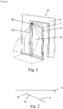
- Fig. 1 shows a door 20 with the door sensor 30 in 3D view.
- the door 20 has a door leaf 21 which is rotatably attached to the wall 10 with door hinges 22.
- the door leaf can be closed or opened in one direction, here in the direction of the observer, so that the door leaf releases the door opening 11.
- the door hinge 20 defines the axis of rotation of the door leaf.
- the axis of rotation is the axis around which the door leaf can be moved by a certain angle of rotation. When the door is closed, the angle of rotation is assumed to be zero. When the door is open at maximum, the door is open at the maximum angle of rotation.
- the door 20 is a swing door that can be opened in one direction only.
- the door and the door leaf have two door sides.
- the first door side is the inside of the door, that is the side in the direction of which the door is opened.
- the second door side is the door outside, this is the side in the direction of the door is closed.
- a door may have one of two directions of rotation.
- the direction of rotation of a door is the side on which the axis of rotation of the door is on the inside of the door.
- the direction of rotation can be clockwise or counterclockwise.
- the door 20 has the axis of rotation on the left side and therefore the left-hand rotation.
- the door sensor 30 is mounted on the door inner side at the top of the side of the rotation axis on the door leaf with a very small clearance (less than 20 cm or less than 10% of the width or height of the door leaf) to the top and side of the door leaf.
- the door sensor 30 monitors the three-dimensional monitoring field 70.
- the thus mounted door sensor is referred to as moving on the door leaf.
- the monitoring field 70 is moving with the door leaf. This means that the monitoring field can be at least partially constant to the door leaf.
- the figure shows a realistic representation of the possible extent of the monitoring field.
- the door 20 is a motor-driven door via a door control and the door sensor is designed to transmit signals to the door control depending on its detection in the monitoring field.
- This can be one Be a safety signal to stop the door, for example if a person is detected in the monitoring field in the movement field of the door leaf.
- This can also be an opening signal for opening the door, for example if a person is detected in the monitoring field, which goes to the door.
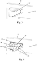
- Fig. 2 shows the door of the Fig. 1 in plan view.
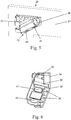
- Fig. 3 shows the door sensor 30 with housing 37 on the door leaf 21 as a detail Fig. 1 ,
- Fig. 4 shows a mounting plate 31 of the door sensor in detail Fig. 3
- the mounting plate 31 has a plane 32 for surface-parallel mounting on the door leaf 21, a horizontal edge 33 for alignment parallel to the upper edge of the door leaf and a vertical edge 34 for alignment parallel to the side edge of the door leaf.
- the mounting plate has support elements 35 for the defined angular orientation of the door sensor with respect to the plane of the door leaf.
- the mounting plate has retaining elements 36 for fixing and defining the angular orientation of the door sensor with respect to the horizontal and upper edges of the door leaf.
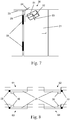
- Fig. 5 also shows the door sensor 30 with the mounting plate 31 on the door leaf 21 as a detail Fig. 3 ,
- the door sensor has a 3D image sensor 40, which has a transmitter 41 and a receiver 42.
- the transmitter transmits 20 MHz modulated IR radiation into the surveillance area.
- the receiver is a pixel matrix sensor which receives the radiation of the transmitter reflected from the monitoring area as an image and is designed to detect, for each of its pixels, the phase shift of the modulation of the received radiation compared to the emitted radiation. Due to the phase shift, the receiver determines the distance of the surface reflecting on this pixel in the interstitial space for each of its pixels and thus generates a 3D image.
- Other door sensors use instead of the phase shift the time of flight of the emitted and reflected radiation which is similar in the end. These door sensors are also called TOF (Time of Flight) sensors.
- the pixels of the receiver used are also called demodulation pixels.
- Fig. 6 also shows the door sensor 30 as a detail FIG. 3 ,
- the support members 35 fix in conjunction with the plane 32 of the mounting plate, the viewing direction and main axes of the door sensor with respect to the plane of the door panel.
- the holding elements 36 fix in connection with the horizontal Edge 33 and the vertical edge 34 of the mounting plate, the viewing direction and main axes of the door sensor with respect to the horizontal and the upper edge of the door leaf.
- the viewing direction and main axis of the door sensor is defined by the optical axes of transmitter 41 and receiver 42.
- Fig. 7 shows the orientation of the door sensor 30 with respect to the door leaf 21 as a detail of the preceding figures.
- the coordinate system of the door leaf has its zero point in the axis of rotation at the upper end of the door leaf.
- the X-axis 23 of the door leaf extends horizontally in the direction of the hinge 22, the Y-axis 24 of the door leaf is perpendicular to the door panel to the door outside, so away from the viewer and the Z-axis 25 of the door leaf is perpendicular to the bottom.
- the coordinate system of the door sensor has its zero point in the door sensor.
- the X-axis 51 of the door sensor is rotated 30 degrees down the Y-axis of the door panel compared to the X-axis of the door panel.
- the Z-axis 53 of the door sensor is rotated 15 ° relative to the plane of the door leaf about the X-axis of the door sensor forward to the viewer.
- the Y-axis 52 of the door sensor results accordingly and points away from the viewer.
- the main direction of the door sensor is thus inclined downwards and is pivoted by 30 ° from the perpendicular to the outer edge of the door panel and 15 ° out of the plane of the door panel forward.
- the door sensor has a 3-axis gyrosensor as a rotary encoder and is not shown in the figures.
- the gyro sensor is oriented according to the coordinate system of the door sensor.
- Fig. 8 shows the four mounting situations of the door sensor 30 on a door panel 30.
- the mounting situation 61 corresponds to the previous figures.
- the mounting situations 62, 63 and 64 do not correspond to the previous figures.
- the mounting situations 61 and 62 show the door sensor 30 on the door inner side of the door panel 21, while the mounting situations 63 and 64 show the door sensor 30 on the door outside of the door panel 21.
- the mounting situations 61 and 63 show the door sensor 30 on a left-handed door, since the hinges 22 are arranged on the left side of the inside of the door.
- the mounting situations 62 and 64 show the door sensor 30 on a right-handed door, since the hinges 22 are arranged on the right side of the inside of the door.
- Mounting situation 61 on the door outside a left-handed door Mounting situation 62: on the door outside a clockwise door Mounting situation 63: on the inside of the door a left-handed door Mounting situation 64: on the inside of the door a clockwise door
- the rotation angle sensor detects a rotation about all 3 axes when opening the door. From this, the door sensor determines the direction of rotation about each of its axes. From the direction of rotation of the 3 axes, the door sensor now clearly determines the correct mounting situation using the following table. A positive direction of rotation in the mathematical sense is indicated here with "+”.
- Fig. 9 shows the monitoring field 71 of the door sensor 30 with the door leaf closed 21.
- the monitoring field 71 terminates at the door outer edge.
- Fig. 10 shows the enlarged monitoring field 72 of the door sensor 30 with slightly open door leaf 21 of the same door Fig. 9 , The monitoring field 72 now extends beyond the door outer edge.
- the door sensor 30 of Fig. 9 and the Fig. 10 is thus adapted to change the monitoring field as a function of the angle of rotation and to increase here with increasing rotation angle.
- the door sensor can be designed so that the maximum magnification is reached at approximately 45 ° rotation angle of the door leaf, so that the monitoring field is reduced again with closed or by 90 ° or fully open door leaf to the end of the door outer edge.
- the angle of rotation for the door leaf of the door after 11, 12 and 13 is limited to a radial boundary line at 90 °, such as by a bottom stop, by a vertically adjacent wall, by a limitation of the door mechanism or by a limitation by the door control of the motorized door drive.
- the door leaf 11 of Fig. 11 is closed and the monitoring field 70 extends as a rectangle to the door leaf adjacent in the width of the door panel perpendicular to the space in front of the door leaf.
- the door leaf 11 of Fig. 12 is around 30 ° and the Fig. 13 opened by 60 ° and the monitoring field 71 extends as a rectangle to the door leaf in the width of the door perpendicular to the space in front of the door leaf, wherein the monitoring field 71 is reduced on the side of the hinge of the door so that the monitoring field does not exceed the radial limit line of the maximum movement of the door leaf extends.
- the door sensor is thus designed to change the extent of the monitoring field as a function of the angle of rotation of the door panel so that the monitoring field is always cut off from the plane of the door panel at the maximum opening angle and therefore does not extend beyond this level.
- a hiding of a wall can be achieved, for example, so that the wall is not detected as obstacle object when approaching the door sensor.
- Door sensor for mounting on the door leaf of a swivel or revolving door with a 3D image sensor for monitoring a monitoring field in front of the door leaf with a rotary encoder for detecting the angle of rotation of the door leaf
- the door sensor has a common carrier which connects the 3D image sensor with the rotary encoder.
- the rotary encoder is an at least 2-axis rotary encoder.
- the rotary encoder is a gyrosensor.
- the common carrier defines a mounting plane for mounting on the door leaf and the rotary encoder is inclined with respect to the mounting plane and arranged in particular inclined by 15 °.
- the common carrier comprises an edge or mark for horizontal and / or vertical alignment of the carrier on the door leaf, and the rotary encoder is inclined with respect to the edge or mark and arranged in particular inclined by 30 °.
- the common carrier has a mounting plate for positionally stable recording of the 3D image sensor and the rotary encoder which has a plane for mounting on the door leaf and / or which comprises an edge or a mark which is intended to be in a horizontal and / or vertical orientation on the door leaf to be arranged, wherein the rotary encoder with respect to two vertical axes in the mounting plane, in particular the main axes of the door leaf is arranged 1-fold or 2-fold inclined.
- the door sensor has a predetermined side for mounting in the direction of the door leaf.
- the rotary encoder is a 3-axis rotary encoder, in particular a 3-axis gyro sensor.
- the door sensor has a memory for storing environmental parameters, in particular the door side (inside door or door outside), the direction of rotation (left or right-hand door) and the maximum angle of rotation of the door leaf.
- a method for teaching parameters for a door sensor for monitoring a monitoring field in front of the door leaf of a door for mounting on the door leaf of a swivel or revolving door with a minimum 2-axis rotary encoder which is at least 1-fold inclined with respect to the door leaf wherein the following method steps performed Use of a minimum 2-axis rotary encoder which is at least 1-fold inclined with respect to the door leaf, opening the door leaf of the closed door, detecting the rotation of both axes of the rotary encoder when opening, determining the direction of rotation of both axes due to their rotation, detection the door side (door inside or door outside) on which the door sensor is mounted on the door leaf due to the direction of rotation of the two axes, storing the door side (inside or outside) in a memory, in particular a memory of the door sensor.
- further method steps are the determination of the direction of rotation of the door leaf (left or right-handed rotation) due to the direction of rotation of at least one axis of the rotary encoder and the storage of the direction of rotation in a memory, in particular in a memory of the door sensor.
- further method steps are opening the door to the maximum, in particular with subsequent reversing, in particular with subsequent closing of the door, detection of the maximum angle of rotation due to stoppage or reversal of motion due to the reversion of the rotation due to the opening to the maximum, and the storage of the maximum angle of rotation in a memory, in particular in a memory of the door sensor.
- a further method step is the use of an at least 2-axis rotary encoder which is 2-fold inclined with respect to the door leaf.
- a further method step is the use of a 3-axis rotary encoder.
- a further method step is the use of a gyro sensor as a rotary encoder.
- Door sensor for mounting on the door leaf of a swiveling or revolving door with a 3D image sensor for monitoring a monitoring field in front of the door leaf with a rotary encoder or a signal input for detecting the rotation angle of the door leaf, wherein the door sensor is adapted to the extent of the monitoring field as a function of the rotation angle to change.
- the door sensor is designed to change the extent of the monitoring field in the direction of the door outer edge as a function of the angle of rotation.
- the door sensor is designed to at least partially increase the expansion with increasing rotation angle.
- the door sensor is designed to initially increase the expansion with increasing rotation angle and then to reduce it again.
- the door sensor is designed to at least partially reduce the expansion as the angle of rotation increases.
- the door sensor is designed to initially reduce the expansion with increasing rotation angle and then to increase again.
- the door sensor is designed to change the extent of the monitoring field in dependence on the maximum angle of rotation of the opening of the door leaf.
- the door sensor is adapted to change the monitoring field so that it does not extend substantially beyond the plane of the door panel at maximum rotation angle, in particular not over a fixed space portion over the Level of the door leaf extends at maximum rotation angle, in particular does not extend beyond the plane of the door panel at maximum rotation angle.
- the door sensor has a common carrier on which connects the 3D image sensor with the rotary encoder.
- the rotary encoder is a gyrosensor.
- the change in the extent of the monitoring field is caused by a change in the evaluated space points.
- Door in particular a pivoting or revolving door with one of the aforementioned door sensors wherein the door sensor is mounted on the surface of the door leaf of the door and in particular mounted on top of the door leaf, in particular in the upper 90% of the door panel is mounted, in particular on the side of Is mounted rotation axis, in particular less than 20%, in particular less than 10% of the width of the door leaf away from the axis of rotation.
Landscapes
- Engineering & Computer Science (AREA)
- Physics & Mathematics (AREA)
- General Physics & Mathematics (AREA)
- Radar, Positioning & Navigation (AREA)
- Remote Sensing (AREA)
- Signal Processing (AREA)
- Multimedia (AREA)
- Burglar Alarm Systems (AREA)
- Power-Operated Mechanisms For Wings (AREA)
Abstract
Description
- Die Erfindung betrifft einen auf dem Türblatt mitfahrenden Türsensor mit Drehwinkelgeber.
- Aus dem Stand der Technik sind Türsensoren bekannt, die auf dem Türblatt einer Schwenktüre montiert sind. Die Patente
EP 2 453 254 A1 ,EP 2 453 260 B1 ,EP 2 698 649 B1 ,EP 2 453 252 B1 undEP 2 667 218 B1 des Anmelders beschreiben einen gattungsgemässen Sensor. - Es ist Aufgabe der Erfindung, einen verbesserten Türsensor bereit zu stellen.
- Diese Aufgabe wird, ausgehend von einem Türsensor der eingangs genannten Art, durch einen Türsensor nach Anspruch 1 und eine Türe nach Anspruch 10 gelöst. Vorteilhafte Ausgestaltungen sind in den weiteren abhängigen Ansprüchen angegeben.
- Der erfindungsgemäße Türsensor ist ein Türsensor zur Montage auf dem Türblatt einer Schwenk- oder Drehtüre mit einem 3D Bildsensor zur Überwachung eines Überwachungsfeldes vor dem Türblatt mit einem Drehwinkelgeber zur Detektion des Drehwinkels des Türblatts wobei der Türsensor einen gemeinsamen Träger aufweist welcher den 3D Bildsensor mit dem Drehwinkelgeber verbindet.
- Der erfindungsgemässe Türsensor kann den Vorteil ausbilden, dass er zur Verarbeitung der Drehwinkels des Türblatts mit dem Türsensor keine Eingabe von aussen benötigt. Daher kann er auch mit einfachen und preiswerten Türsteuerungen verwendet werden.
- Vorzugsweise ist der Drehwinkelgeber ein mindestens 2-Achsen Drehwinkelgeber. Dies kann den Vorteil ausbilden, dass der Türsensor seine Montagesituation erkennen kann.
- Vorzugsweise ist der Drehwinkelgeber ein Gyrosensor. Dies kann den Vorteil ausbilden, dass der Türsensor preiswert und klein ausgeführt werden kann.
- Vorzugsweise definiert der gemeinsame Träger eine Montageebene zur Montage am Türblatt und der Drehwinkelgeber ist in Bezug auf die Montageebene geneigt angeordnet und insbesondere um 15° geneigt angeordnet. Dies kann den Vorteil ausbilden, dass der Gyrosensor innerhalb des Türsensors nach den Hauptachsen des Türsensors ausgerichtet werden kann.
- Vorzugsweise umfasst der gemeinsame Träger eine Kante oder Markierung zur waagrechten und/oder senkrechten Ausrichtung des Trägers am Türblatt, und der Drehwinkelgeber ist in Bezug auf die Kante oder Markierung geneigt angeordnet und insbesondere um 30° geneigt angeordnet. Dies kann den Vorteil ausbilden, dass der Gyrosensor innerhalb des Türsensors nach den Hauptachsen des Türsensors ausgerichtet werden kann.
- Vorzugsweise weist der gemeinsame Träger eine Montageplatte zur positionsstabilen Aufnahme des 3D Bildsensors und des Drehwinkelgebers auf welche eine Ebene zur Montage am Türblatt aufweist und/oder welche einer Kante oder einer Markierung umfasst die dazu vorgesehen ist, in waagrechter und/oder senkrechter Ausrichtung auf dem Türblatt angeordnet zu werden, wobei der Drehwinkelgeber in Bezug auf zwei senkrechte Achsen in der Montageebene, insbesondere die Hauptachsen des Türblatts 1-fach oder 2-fach geneigt angeordnet ist. Dies kann den Vorteil ausbilden, dass Montage und Ausrichtung des Türsensors samt Gyrosensor in Bezug auf das Türblatt einfach und präzise erfolgen kann.
- Vorzugsweise weist der Türsensor eine vorbestimmte Seite zur Montage in Richtung des Türblatts auf. Dies kann den Vorteil ausbilden, dass die verdrehungssichere Montage einfach und zuverlässig erfolgen kann.
- Vorzugsweise ist der Drehwinkelgeber ein 3-Achsen Drehwinkelgeber, insbesondere ein 3-Achsen Gyrosensor. Dies kann den Vorteil ausbilden, dass ein handelsüblicher und damit preiswerter Gyrosensor verwendet werden kann.
- Vorzugsweise weist der Türsensor einen Speicher zur Speicherung von Umgebungsparametern auf, insbesondere der Türseite (Türinnenseite oder Türaussenseite), der Drehrichtung (links- oder rechtsdrehende Türe) und des maximalen Drehwinkels des Türblatts. Dies kann den Vorteil aufweisen, das dem Türsensor Umgebungsvariablen eingelernt werden kann.
- Die erfindungsgemässe Türe ist eine Türe, insbesondere eine Schwenk- oder Drehtüre mit einem der vorgenannten Türsensoren wobei der Türsensor auf der Fläche des Türblatts der Türe angebracht ist und insbesondere oben auf dem Türblatt angebracht ist, insbesondere in den oberen 90% des Türblatts angebracht ist, insbesondere auf der Seite der Drehachse, insbesondere weniger als 20%, insbesondere weniger als 10% der Breite des Türblatts von der Drehachse entfernt angebracht ist. Die erfindungsgemässe Türe kann die vorgenannten Vorteile ausbilden.
- Weitere Merkmale der Erfindung sind in den Zeichnungen und der Zusammenfassung angegeben.
- Die jeweils genannten Vorteile können sich auch für Merkmalskombinationen realisieren in deren Zusammenhang sie nicht genannt sind.
- Ein Ausführungsbeispiel der Erfindung ist in den Zeichnungen dargestellt. Alle Zeichnungen betreffen den selben erfindungsgemässen Türsensor in gleicher Anordnung am Türblatt, falls nicht ausdrücklich anders dargelegt. Gleiche Bezugszeichen in den einzelnen Figuren bezeichnen dabei einander entsprechende Elemente. Es zeigen:
- Fig. 1
- Türe mit Türsensor in 3D Ansicht
- Fig. 2
- Türe mit Türsensor in Draufsicht
- Fig. 3
- Türsensor mit Gehäuse
- Fig. 4
- Montageplatte des Türsensors
- Fig. 5
- Türsensor auf Montageplatte
- Fig. 6
- Türsensor auf Montageplatte
- Fig. 7
- Ausrichtung des Türsensors
- Fig. 8
- Montagesituationen
- Fig. 9
- Überwachungsfeld einer geschlossenen Türe
- Fig. 10
- Überwachungsfeld einer geöffneten Türe
- Fig. 11
- Hinteres Überwachungsfeld bei geschlossener Türe
- Fig. 12
- Hinteres Überwachungsfeld bei leicht geöffneter Türe
- Fig. 13
- Hinteres Überwachungsfeld bei weiter geöffneter Türe
-
Fig. 1 zeigt eine Türe 20 mit dem Türsensor 30 in 3D Ansicht. - Die Türe 20 weist ein Türblatt 21 auf welches mit Türscharnieren 22 drehbar an der Wand 10 befestigt ist. Das Türblatt kann geschlossen werden oder in eine Richtung, hier in Richtung des Betrachters, geöffnet werden, sodass das Türblatt die Türöffnung 11 frei gibt.
- Das Türscharnier 20 legt die Drehachse des Türblatts fest. Die Drehachse ist die Achse um die das Türblatt um einen bestimmten Drehwinkel bewegt werden kann. Bei geschlossener Türe wird der Drehwinkel Null angenommen. Bei maximal geöffneter Türe ist die Türe im maximalen Drehwinkel geöffnet.
- Die Türe 20 ist eine Schwenktüre, die in nur eine Richtung zu öffnen ist.
Die Türe und das Türblatt weisen zwei Türseiten auf. Die erste Türseite ist die Türinnenseite, das ist die Seite, in deren Richtung die Tür geöffnet wird. Die zweite Türseite ist die Türaussenseite, das ist die Seite in deren Richtung die Türe geschlossen wird. - Eine Türe kann eine von zwei Drehrichtungen aufweisen. Die Drehrichtung einer Türe ist die Seite an welcher die Drehachse der Türe auf der Türinnenseite ist. Die Drehrichtung kann rechtsdrehend oder linksdrehend sein. Die Türe 20 hat die Drehachse auf der linken Seite und daher die linksdrehend.
- Auf dem Türblatt 21 ist auf der Türinnenseite oben auf der Seite der Drehachse auf dem Türblatt mit sehr geringem Abstand (kleiner 20 cm oder kleiner 10% der Breite bzw. Höhe des Türblatts) zum oberen und seitlichen Abschluss des Türblatts der Türsensor 30 montiert. Der Türsensor 30 überwacht das dreidimensionale Überwachungsfeld 70. Der so montierte Türsensor wird als auf dem Türblatt mitfahrend bezeichnet. Ebenso ist das Überwachungsfeld 70 mit dem Türblatt mitfahrend. Das heisst, das Überwachungsfeld kann mindestens teilweise konstant zum Türblatt sein. Die Figur zeigt eine realistische Darstellung der möglichen Ausdehnung des Überwachungsfeldes.
- Die Türe 20 ist eine über eine Türsteuerung motorisch angetriebene Türe und der Türsensor ist dazu ausgelegt, in Abhängigkeit von seiner Detektion im Überwachungsfeld Signale an die Türsteuerung zu übergeben. Dies kann ein Sicherheitssignal zum Stopp der Türe sein, etwa falls eine Person im Überwachungsfeld im Bewegungsfeld des Türblatts detektiert wird. Dies kann auch ein Öffnungssignal zum Öffnen der Türe sein, etwa falls eine Person im Überwachungsfeld detektiert wird, die auf die Türe zu geht.
-
Fig. 2 zeigt die Türe derFig. 1 in Draufsicht. -
Fig. 3 zeigt den Türsensor 30 mit Gehäuse 37 am Türblatt 21 als Detail ausFig. 1 . -
Fig. 4 zeigt eine Montageplatte 31 des Türsensors als Detail ausFig. 3 . Die Montageplatte 31 weist eine Ebene 32 zur flächenparallelen Montage am Türblatt 21 auf, eine waagrechte Kante 33 zur Ausrichtung parallel zur Oberkante des Türblatts und eine senkrechte Kante 34 zur Ausrichtung parallel zur Seitenkante des Türblatts. Die Montageplatte weist Stützelemente 35 auf zur definierten Winkelausrichtung des Türsensors in Bezug auf die Ebene des Türblatts. Die Montageplatte weist Halteelemente 36 auf, zur Fixierung und definierten Winkelausrichtung des Türsensors in Bezug auf die Waagrechte und Oberkante des Türblatts. -
Fig. 5 zeigt den Türsensor 30 mit der Montageplatte 31 auf dem Türblatt 21 ebenfalls als Detail ausFig. 3 . Der Türsensor weist einen 3D Bildsensor 40 auf welcher einen Sender 41 und einen Empfänger 42 aufweist. Der Sender sendet mit 20 MHz modulierte IR Strahlung in den Überwachungsbereich. Der Empfänger ist ein Pixel-Matrixsensor welcher die aus dem Überwachungsbereich reflektierte Strahlung des Senders als Bild empfängt und dazu ausgebildet ist, für jeden seiner Pixel die Phasenverschiebung der Modulation der empfangenen Strahlung im Vergleich zur ausgesandten Strahlung zu detektieren. Aufgrund der Phasenverschiebung ermittelt der Empfänger für jedes seiner Pixel den Abstand der auf dieses Pixel reflektierenden Oberfläche im Überwachungsraum und generiert so ein 3D Bild. Andere Türsensoren benutzen statt der Phasenverschiebung die Flugzeit der ausgesandten und reflektieren Strahlung was im Endeffekt ähnlich ist. Diese Türsensoren werden auch TOF (Time of Flight) Sensoren genannt. Die Pixel des verwendeten Empfängers werden auch Demodulationspixel genannt. -
Fig. 6 zeigt den Türsensor 30 ebenfalls als Detail ausFigur 3 . Die Stützelemente 35 fixieren in Zusammenhang mit der Ebene 32 der Montageplatte die Blickrichtung und Hauptachsen des Türsensors in Bezug auf die Ebene des Türblatts. Die Halteelemente 36 fixieren in Zusammenhang mit der waagrechten Kante 33 und der senkrechten Kante 34 der Montageplatte die Blickrichtung und Hauptachsen des Türsensors in Bezug auf die Waagrechen und die Oberkante des Türblatts. Die Blickrichtung und Hauptachse des Türsensors wird durch die optischen Achsen von Sender 41 und Empfänger 42 definiert. -
Fig. 7 zeigt die Ausrichtung des Türsensors 30 in Bezug auf das Türblatt 21 als Detail der vorhergehenden Figuren. - Das Koordinatensystem des Türblatts hat seinen Nullpunkt in der Drehachse am oberen Ende des Türblatts. Die X-Achse 23 des Türblatts verläuft waagrecht in Richtung des Scharniers 22, die Y-Achse 24 des Türblatts verläuft lotrecht zur Ebene des Türblatts zur Türaussenseite, also vom Betrachter weg und die Z-Achse 25 des Türblatts verläuft senkrecht nach unten.
- Das Koordinatensystem des Türsensors hat seinen Nullpunkt im Türsensor. Die X-Achse 51 des Türsensors ist im Vergleich zur X-Achse des Türblatts um 30° um die Y-Achse des Türblatts nach unten gedreht. Die Z-Achse 53 des Türsensors ist im Vergleich zur Ebene des Türblatts um 15° um die X-Achse des Türsensors nach vorn zum Betrachter hingedreht. Die Y-Achse 52 des Türsensors ergibt sich entsprechend und zeigt vom Betrachter weg. Die Hauptblickrichtung des Türsensors geht also schräg nach unten und ist um 30° aus der Senkrechten zur Aussenkante des Türblatts und um 15° aus der Ebene des Türblatts nach vorn geschwenkt.
- Der Türsensor weist einen 3-Achsen Gyrosensor als Drehwinkelgeber auf und ist in den Figuren nicht dargestellt. Der Gyrosensor ist gemäss dem Koordinatensystem des Türsensors orientiert.
-
Fig. 8 zeigt die vier Montagesituationen des Türsensors 30 an einem Türblatt 30. Die Montagesituation 61 entspricht den vorhergehenden Figuren. Die Montagesituationen 62, 63 und 64 entsprechen nicht den vorhergehenden Figuren. - Die Montagesituationen 61 und 62 zeigen den Türsensor 30 auf der Türinnenseite des Türblatts 21, während die Montagesituationen 63 und 64 den Türsensor 30 auf der Türaussenseite des Türblatts 21 zeigen. Die Montagesituationen 61 und 63 zeigen den Türsensor 30 an einer linksdrehenden Türe, da die Scharniere 22 auf der linken Seite der Türinnenseite angeordnet sind. Die Montagesituationen 62 und 64 zeigen den Türsensor 30 an einer rechtsdrehenden Türe, da die Scharniere 22 auf der rechten Seite der Türinnenseite angeordnet sind.
- Es gibt also vier unterschiedliche Montagesituationen die durch die Kombination aus den beiden möglichen Türseiten (Türinnenseite oder Türaussenseite) und den beiden möglichen Drehrichtungen des Türblatts (rechtsdrehend oder linksdrehend) gegeben sind. Dies sind im Einzelnen:
Montagesituation 61: auf Türaussenseite einer linksdrehende Türe Montagesituation 62: auf Türaussenseite einer rechtsdrehenden Türe Montagesituation 63: auf Türinnenseite einer linksdrehende Türe Montagesituation 64: auf Türinnenseite einer rechtsdrehenden Türe - In einem Lernmodus detektiert der Drehwinkelsensor beim Öffnen der Türe eine Drehung um alle 3 Achsen. Daraus ermittelt der Türsensor die Drehrichtung um jede seiner Achsen. Aus der Drehrichtung der 3 Achsen ermittelt der Türsensor nun eindeutig die zutreffende Montagesituation anhand der folgenden Tabelle. Eine positive Drehrichtung im mathematischen Sinn ist hier mit "+" angegeben.
Drehrichtung X-Achse Drehrichtung Y-Achse Drehrichtung Z-Achse Montagesituation + + + 61 - + - 62 + - + 63 - - - 64 - Aus der Tabelle ist ersichtlich, dass die Detektion von nur 2 Achsen ausreichen würde, wenn dies die Achsen X und Y oder Y und Z sind, da auch allein mit diesen Achsen eine eindeutige Zuordnung der Montagesituation möglich ist. Insofern ist es ausreichend, für den Türsensor einen 2-Achsen Drehwinkelgeber zu verwenden.
- Ebenso soll angemerkt werden, dass es ausreichend ist, das Koordinatensystem des Drehwinkelgebers lediglich um eine Achse gegenüber dem Türblatt zu verdrehen. Es ist also ausreichend die Z-Achse 53 des Drehwinkelgebers im Vergleich zur Ebene des Türblatts um 15° um die X-Achse des Türsensors nach vorn zum Betrachter hin zu verdrehen. Die X-Achse des Drehwinkelgebers kann also parallel zur X-Achse des Türblatts verbleiben.
-
Fig. 9 zeigt das Überwachungsfeld 71 des Türsensors 30 mit geschlossenem Türblatt 21. Das Überwachungsfeld 71 endet an der Türaussenkante. -
Fig. 10 zeigt das vergrösserte Überwachungsfeld 72 des Türsensors 30 mit leicht geöffnetem Türblatt 21 der gleichen Türe derFig. 9 . Das Überwachungsfeld 72 reicht nun über die Türaussenkante hinaus. Der Türsensor 30 derFig. 9 und derFig. 10 ist also dazu ausgebildet, das Überwachungsfeld in Abhängigkeit des Drehwinkels zu verändern und hier mit zunehmendem Drehwinkel zu vergrössern. - Der Türsensor kann dazu ausgelegt sein, dass die maximale Vergrösserung etwa bei 45° Drehwinkel des Türblatts erreicht ist, sodass das Überwachungsfeld bei geschlossener oder um 90° oder vollständig geöffnetem Türblatt wieder zum Ende der Türaussenkante reduziert ist.
-
Fig. 11, Fig. 12 und Fig. 13 zeigten jeweils eine Türe mit einem Türblatt 21 mit einem Türsensor 30 und dem Überwachungsfeld 70, 71 bei verschiedenen Drehwinkeln des Türblatts in Draufsicht. - Der Drehwinkel für das Türblatt der Türe nach
Fig. 11, Fig. 12 und Fig. 13 ist auf eine radiale Begrenzungslinie bei 90° begrenzt, etwa durch einen Bodenanschlag, durch eine senkrecht angrenzende Wand, durch eine Begrenzung der Türmechanik oder durch eine Begrenzung durch die Türsteuerung des motorischen Türantriebs. - Das Türblatt 11 der
Fig. 11 ist geschlossen und das Überwachungsfeld 70 erstreckt sich als Rechteck an das Türblatt angrenzend in der Breite des Türblatts senkrecht in den Raum vor dem Türblatt. - Das Türblatt 11 der
Fig. 12 ist um 30° und derFig. 13 um 60° geöffnet und das Überwachungsfeld 71 erstreckt sich als Rechteck an das Türblatt angrenzend in der Breite des Türblatts senkrecht in den Raum vor dem Türblatt, wobei das Überwachungsfeld 71 auf der Seite des Scharniers der Türe so vermindert ist, dass das Überwachungsfeld nicht über die radiale Begrenzungslinie der maximalen Bewegung des Türblatts hinausreicht. - Der Türsensor ist also dazu ausgelegt, die Ausdehnung des Überwachungsfeldes in Abhängigkeit des Drehwinkels des Türblatts so zu ändern, dass das Überwachungsfeld von der Ebene des Türblatts bei maximalem Öffnungswinkel stets abgeschnitten ist und also nicht über diese Ebene hinausreicht. Dadurch kann etwa auch ein Ausblenden einer Wand erreicht werden, damit die Wand bei der Annäherung des Türsensors nicht als Hindernis-Objekt detektiert wird.
- Türsensor zur Montage auf dem Türblatt einer Schwenk- oder Drehtüre mit einem 3D Bildsensor zur Überwachung eines Überwachungsfeldes vor dem Türblatt mit einem Drehwinkelgeber zur Detektion des Drehwinkels des Türblatts wobei der Türsensor einen gemeinsamen Träger aufweist welcher den 3D Bildsensor mit dem Drehwinkelgeber verbindet. Vorzugsweise ist der Drehwinkelgeber ein mindestens 2-Achsen Drehwinkelgeber. Vorzugsweise ist der Drehwinkelgeber ein Gyrosensor. Vorzugsweise definiert der gemeinsame Träger eine Montageebene zur Montage am Türblatt und der Drehwinkelgeber ist in Bezug auf die Montageebene geneigt angeordnet und insbesondere um 15° geneigt angeordnet. Vorzugsweise umfasst der gemeinsame Träger eine Kante oder Markierung zur waagrechten und/oder senkrechten Ausrichtung des Trägers am Türblatt, und der Drehwinkelgeber ist in Bezug auf die Kante oder Markierung geneigt angeordnet und insbesondere um 30° geneigt angeordnet. Vorzugsweise weist der gemeinsame Träger eine Montageplatte zur positionsstabilen Aufnahme des 3D Bildsensors und des Drehwinkelgebers auf welche eine Ebene zur Montage am Türblatt aufweist und/oder welche einer Kante oder einer Markierung umfasst die dazu vorgesehen ist, in waagrechter und/oder senkrechter Ausrichtung auf dem Türblatt angeordnet zu werden, wobei der Drehwinkelgeber in Bezug auf zwei senkrechte Achsen in der Montageebene, insbesondere die Hauptachsen des Türblatts 1-fach oder 2-fach geneigt angeordnet ist. Vorzugsweise weist der Türsensor eine vorbestimmte Seite zur Montage in Richtung des Türblatts auf. Vorzugsweise ist der Drehwinkelgeber ein 3-Achsen Drehwinkelgeber, insbesondere ein 3-Achsen Gyrosensor. Vorzugsweise weist der Türsensor einen Speicher zur Speicherung von Umgebungsparametern auf, insbesondere der Türseite (Türinnenseite oder Türaussenseite), der Drehrichtung (links- oder rechtsdrehende Türe) und des maximalen Drehwinkels des Türblatts.
- Verfahren zum Einlernen von Parametern für einen Türsensor zur Überwachung eines Überwachungsfeldes vor dem Türblatt einer Türe zur Montage auf dem Türblatt einer Schwenk- oder Drehtüre mit einem mindestens 2-achsigen Drehwinkelgeber welcher in Bezug auf das Türblatt mindestens 1-fach geneigt ist wobei folgende Verfahrensschritte ausgeführt werden: Verwendung eines mindestens 2-achsigen Drehwinkelgebers welcher in Bezug auf das Türblatt mindestens 1-fach geneigt ist, Öffnen des Türblattes der geschlossenen Türe, Detektion der Drehung beider Achsen des Drehwinkelgebers beim Öffnen, Ermittlung der Drehrichtung beider Achsen aufgrund deren Drehung, Ermittlung der Türseite (Türinnenseite oder Türaussenseite) an der der Türsensor am Türblatt montiert ist aufgrund der Drehrichtung der beiden Achsen, Speicherung der Türseite (innen oder aussen) in einem Speicher, insbesondere einem Speicher des Türsensors. Vorzugsweise sind weitere Verfahrensschritte die Ermittlung der Drehrichtung des Türblatts (links- oder rechtsdrehend) aufgrund der Drehrichtung mindestens einer Achse des Drehwinkelgebers und die Speicherung der Drehrichtung in einem Speicher, insbesondere in einem Speicher des Türsensors. Vorzugsweise sind weitere Verfahrensschritte das Öffnen der Türe bis zum Maximum, insbesondere mit anschliessendem Reversieren, insbesondere mit anschliessendem Schliessen der Türe, Detektion des maximalen Drehwinkels aufgrund des Stillstandes oder der Bewegungsumkehr aufgrund der Reversion der Drehung aufgrund des Öffnens bis zum Maximum, und die Speicherung des maximalen Drehwinkels in einem Speicher, insbesondere in einem Speicher des Türsensors. Vorzugsweise ist ein weiterer Verfahrensschritt die Verwendung eines mindestens 2-achsigen Drehwinkelgebers welcher in Bezug auf das Türblatt 2-fach geneigt ist. Vorzugsweise ist ein weiterer Verfahrensschritt die Verwendung eines 3-achsigen Drehwinkelgebers. Vorzugsweise ist ein weiterer Verfahrensschritt die Verwendung eines Gyrosensors als Drehwinkelgeber.
- Türsensor zur Montage auf dem Türblatt einer Schwenk- oder Drehtüre mit einem 3D Bildsensor zur Überwachung eines Überwachungsfeldes vor dem Türblatt mit einem Drehwinkelgeber oder einem Signaleingang zur Erfassung des Drehwinkels des Türblatts wobei der Türsensor dazu ausgebildet ist, die Ausdehnung des Überwachungsfelds in Abhängigkeit des Drehwinkels zu ändern. Vorzugsweise ist der Türsensor dazu ausgebildet, die Ausdehnung des Überwachungsfeldes in Richtung der Türaussenkante in Abhängigkeit des Drehwinkels zu ändern. Vorzugsweise ist der Türsensor dazu ausgebildet, die Ausdehnung mit zunehmendem Drehwinkel mindestens teilweise zu vergrössern. Vorzugsweise ist der Türsensor dazu ausgebildet, die Ausdehnung mit zunehmendem Drehwinkel zunächst zu vergrössern und dann wieder zu verringern. Vorzugsweise ist der Türsensor dazu ausgebildet, die Ausdehnung mit zunehmendem Drehwinkel mindestens teilweise zu verringern. Vorzugsweise ist der Türsensor dazu ausgebildet, die Ausdehnung mit zunehmendem Drehwinkel zunächst zu verringern und dann wieder zu vergrössern. Vorzugsweise ist der Türsensor dazu ausgebildet, die Ausdehnung des Überwachungsfeldes in Abhängigkeit des maximalen Drehwinkels der Öffnung des Türblatts zu ändern. Vorzugsweise ist der Türsensor dazu ausgebildet, das Überwachungsfeld so zu ändern, dass es im Wesentlichen nicht über die Ebene des Türblatts bei maximalem Drehwinkel hinausreicht, insbesondre nicht über einen festgelegten Raumabschnitt über die Ebene des Türblatts bei maximalem Drehwinkel hinausreicht, insbesondre nicht über die Ebene des Türblatts bei maximalem Drehwinkel hinausreicht. Vorzugsweise weist der Türsensor einen gemeinsamen Träger auf welcher den 3D Bildsensor mit dem Drehwinkelgeber verbindet. Vorzugsweise ist der Drehwinkelgeber ein Gyrosensor. Vorzugsweise ist die Änderung der Ausdehnung des Überwachungsfeldes durch eine Änderung der ausgewerteten Raumpunkte bewirkt.
- Türe, insbesondere eine Schwenk- oder Drehtüre mit einem der vorgenannten Türsensoren wobei der Türsensor auf der Fläche des Türblatts der Türe angebracht ist und insbesondere oben auf dem Türblatt angebracht ist, insbesondere in den oberen 90% des Türblatts angebracht ist, insbesondere auf der Seite der Drehachse, insbesondere weniger als 20%, insbesondere weniger als 10% der Breite des Türblatts von der Drehachse entfernt angebracht ist.
-
- 10
- Wand
- 11
- Türöffnung
- 20
- Tür
- 21
- Türblatt
- 22
- Türscharnier
- 23
- X-Achse des Türblatts
- 24
- Y-Achse des Türblatts
- 25
- Z-Achse des Türblatts
- 30
- Türsensor
- 31
- Montageplatte
- 32
- Ebene der Montageplatte
- 33
- Waagrechte Kante der Montageplatte
- 34
- Senkrechte Kante der Montageplatte
- 35
- Stützelemente
- 36
- Halteelemente
- 37
- Gehäuse
- 40
- 3D Bildsensor
- 41
- Sender
- 42
- Empfänger
- 50
- 3-Achsen Gyrosensor
- 51
- X-Achse des Gyrosensors
- 52
- Y-Achse des Gyrosensors
- 53
- Z-Achse des Gyrosensors
- 61
- 1. Fall der Anordnung
- 62
- 2. Fall der Anordnung
- 63
- 3. Fall der Anordnung
- 64
- 4. Fall der Anordnung
- 70
- Überwachungsfeld
- 71
- reduziertes Überwachungsfeld
- 72
- vergrössertes Überwachungsfeld
Claims (10)
- Türsensor (30)- zur Montage auf dem Türblatt (21) einer Schwenk- oder Drehtüre (20)- mit einem 3D Bildsensor (40)- zur Überwachung eines Überwachungsfeldes (70,71,72) vor dem Türblatt- mit einem Drehwinkelgeberdadurch gekennzeichnet, dass- zur Detektion des Drehwinkels des Türblatts- der Türsensor einen gemeinsamen Träger (31) aufweist- welcher den 3D Bildsensor mit dem Drehwinkelgeber verbindet.
- Türsensor nach einem der vorgenannten Ansprüche, dadurch gekennzeichnet,- dass der Drehwinkelgeber ein mindestens 2-Achsen Drehwinkelgeber ist.
- Türsensor nach einem der vorgenannten Ansprüche, dadurch gekennzeichnet,- dass der Drehwinkelgeber ein Gyrosensor ist.
- Türsensor nach einem der vorgenannten Ansprüche, dadurch gekennzeichnet,- dass der gemeinsame Träger- eine Montageebene (32) zur Montage am Türblatt definiert und- der Drehwinkelgeber- in Bezug auf die Montageebene geneigt angeordnet ist- und insbesondere um 15° geneigt angeordnet ist.
- Türsensor nach einem der vorgenannten Ansprüche, dadurch gekennzeichnet,- dass der gemeinsame Träger- eine Kante (33, 34) oder Markierung zur waagrechten und/oder senkrechten Ausrichtung des Trägers am Türblatt umfasst,- und der Drehwinkelgeber- in Bezug auf die Kante oder Markierung geneigt angeordnet ist- und insbesondere um 30° geneigt angeordnet ist.
- Türsensor nach einem der vorgenannten Ansprüche, dadurch gekennzeichnet,- dass der gemeinsame Träger eine Montageplatte (31) zur positionsstabilen Aufnahme des 3D Bildsensors und des Drehwinkelgebers aufweist- welche eine Ebene zur Montage am Türblatt aufweist und/oder- welche einer Kante oder einer Markierung umfasst die dazu vorgesehen ist, in waagrechter und/oder senkrechter Ausrichtung auf dem Türblatt angeordnet zu werden,- wobei der Drehwinkelgeber in Bezug auf zwei senkrechte Achsen in der Montageebene, insbesondere die Hauptachsen des Türblatts 1-fach oder 2-fach geneigt angeordnet ist.
- Türsensor nach einem der vorgenannten Ansprüche, dadurch gekennzeichnet,- dass der Türsensor eine vorbestimmte Seite zur Montage in Richtung des Türblatts aufweist.
- Türsensor nach einem der vorgenannten Ansprüche, dadurch gekennzeichnet,- dass der Drehwinkelgeber ein 3-Achsen Drehwinkelgeber ist,- insbesondere, dass der Drehwinkelgeber ein 3-Achsen Gyrosensor ist.
- Türsensor nach einem der vorgenannten Ansprüche, dadurch gekennzeichnet,- dass dieser einen Speicher zur Speicherung von Umgebungsparametern aufweist.
- Türe, insbesondere eine Schwenk- oder Drehtüre- mit einem Türsensor nach einem der vorgenannten Ansprüche,dadurch gekennzeichnet, dass- der Türsensor auf dem Türblatt der Türe angebracht ist- insbesondere oben auf dem Türblatt angebracht ist und- insbesondere auf der Seite der Drehachse angebracht ist.
Priority Applications (3)
| Application Number | Priority Date | Filing Date | Title |
|---|---|---|---|
| EP18157281.9A EP3527954B1 (de) | 2018-02-16 | 2018-02-16 | Türsensor mit drehwinkelgeber |
| US16/268,847 US10947768B2 (en) | 2018-02-16 | 2019-02-06 | Door sensor with rotation angle encoder |
| CN201910116010.4A CN110160485B (zh) | 2018-02-16 | 2019-02-15 | 具有转动角度编码器的门传感器 |
Applications Claiming Priority (1)
| Application Number | Priority Date | Filing Date | Title |
|---|---|---|---|
| EP18157281.9A EP3527954B1 (de) | 2018-02-16 | 2018-02-16 | Türsensor mit drehwinkelgeber |
Publications (2)
| Publication Number | Publication Date |
|---|---|
| EP3527954A1 true EP3527954A1 (de) | 2019-08-21 |
| EP3527954B1 EP3527954B1 (de) | 2022-03-30 |
Family
ID=61231191
Family Applications (1)
| Application Number | Title | Priority Date | Filing Date |
|---|---|---|---|
| EP18157281.9A Active EP3527954B1 (de) | 2018-02-16 | 2018-02-16 | Türsensor mit drehwinkelgeber |
Country Status (3)
| Country | Link |
|---|---|
| US (1) | US10947768B2 (de) |
| EP (1) | EP3527954B1 (de) |
| CN (1) | CN110160485B (de) |
Cited By (2)
| Publication number | Priority date | Publication date | Assignee | Title |
|---|---|---|---|---|
| EP3907367A1 (de) * | 2020-05-08 | 2021-11-10 | GEZE GmbH | Automatische fensteranlage |
| EP3765695B1 (de) * | 2018-03-13 | 2024-08-21 | Pepperl+Fuchs SE | Türsensoreinrichtung und verfahren zum betreiben einer türsensoreinrichtung |
Families Citing this family (9)
| Publication number | Priority date | Publication date | Assignee | Title |
|---|---|---|---|---|
| US10808447B2 (en) | 2017-04-25 | 2020-10-20 | Masonite Corporation | Emergency door closing device |
| US11174664B2 (en) | 2018-03-20 | 2021-11-16 | Masonite Corporation | Door positioning system |
| US11396975B2 (en) | 2019-07-08 | 2022-07-26 | Rick Hagel | Removable or adjustable cover for garage door sensor |
| US11125004B2 (en) * | 2019-07-08 | 2021-09-21 | Rick Hagel | Removable or adjustable cover for garage door sensor |
| JP1677183S (de) | 2019-10-31 | 2021-01-18 | ||
| CN113266994B (zh) * | 2020-02-17 | 2022-10-25 | 青岛海尔电冰箱有限公司 | 冰箱及冰箱检测方法 |
| CN111577059B (zh) * | 2020-04-17 | 2021-09-28 | 佛山科学技术学院 | 基于数字陀螺仪的门开关检测系统 |
| CN111491085B (zh) * | 2020-04-21 | 2021-11-05 | Oppo广东移动通信有限公司 | 图像传感器、摄像装置及电子设备 |
| CN113878614B (zh) * | 2021-09-27 | 2024-05-24 | 山东新一代信息产业技术研究院有限公司 | 一种增加室外巡检机器人重心平衡的方法及系统 |
Citations (8)
| Publication number | Priority date | Publication date | Assignee | Title |
|---|---|---|---|---|
| US20040140782A1 (en) * | 2002-07-09 | 2004-07-22 | Junichiro Okabe | Door sensor and door equipped with such door sensor |
| DE102007038421B3 (de) * | 2007-08-14 | 2008-09-11 | Pepperl + Fuchs Gmbh | Sicherheitsvorrichtung und Verfahren zum Überwachen einer automatischen Tür |
| DE102009024601A1 (de) * | 2008-10-23 | 2010-04-29 | Pepperl + Fuchs Gmbh | Türüberwachungssensor und Verfahren zum Betrieb eines Türüberwachungssensors |
| EP2453254A1 (de) | 2010-11-15 | 2012-05-16 | Cedes AG | Vorrichtung zur Überwachung einer Tür mit einem 3-D-Sensor |
| WO2012071664A1 (en) * | 2010-12-03 | 2012-06-07 | Sensotech Inc. | Adaptive ultrasound detecting system for a door assembly |
| GB2498315A (en) * | 2010-10-29 | 2013-07-10 | Optex Co Ltd | Automatic door sensor and functionality expansion module used for same |
| EP2453260B1 (de) | 2010-11-15 | 2014-04-30 | Cedes AG | Überwachungssensor mit Selbstprüfung |
| EP2453252B1 (de) | 2010-11-15 | 2015-06-10 | Cedes AG | Energiespar-3D-sensor |
Family Cites Families (9)
| Publication number | Priority date | Publication date | Assignee | Title |
|---|---|---|---|---|
| ATE387620T1 (de) * | 2004-07-22 | 2008-03-15 | Bea Sa | Lichtabtastvorrichtung zur detektion um automatische türen |
| JP4915246B2 (ja) * | 2007-01-26 | 2012-04-11 | セイコーエプソン株式会社 | ジャイロモジュール |
| US20120127317A1 (en) * | 2010-11-19 | 2012-05-24 | Bea, Inc. | Method and device to securely open and close a passageway or access point |
| US9329035B2 (en) * | 2011-12-12 | 2016-05-03 | Heptagon Micro Optics Pte. Ltd. | Method to compensate for errors in time-of-flight range cameras caused by multiple reflections |
| GB2511069B (en) * | 2013-02-21 | 2015-06-17 | Dale Read | Energy usage monitoring system |
| DE102013221494A1 (de) * | 2013-10-23 | 2015-04-23 | Robert Bosch Gmbh | Verfahren und Vorrichtung zum Bestimmen eines Drehwinkels eines Objekts um eine Drehachse |
| US9217272B2 (en) * | 2013-11-12 | 2015-12-22 | Complete Entry Systems and Services (2004) Inc. | Automatic door with emergency rescue system |
| US11136812B2 (en) * | 2016-05-09 | 2021-10-05 | Milbat—Giving Quality to Life | Motorized door opening device |
| US10551407B2 (en) * | 2016-07-29 | 2020-02-04 | Blackberry Limited | Determining an open/close status of a barrier |
-
2018
- 2018-02-16 EP EP18157281.9A patent/EP3527954B1/de active Active
-
2019
- 2019-02-06 US US16/268,847 patent/US10947768B2/en active Active
- 2019-02-15 CN CN201910116010.4A patent/CN110160485B/zh active Active
Patent Citations (10)
| Publication number | Priority date | Publication date | Assignee | Title |
|---|---|---|---|---|
| US20040140782A1 (en) * | 2002-07-09 | 2004-07-22 | Junichiro Okabe | Door sensor and door equipped with such door sensor |
| DE102007038421B3 (de) * | 2007-08-14 | 2008-09-11 | Pepperl + Fuchs Gmbh | Sicherheitsvorrichtung und Verfahren zum Überwachen einer automatischen Tür |
| DE102009024601A1 (de) * | 2008-10-23 | 2010-04-29 | Pepperl + Fuchs Gmbh | Türüberwachungssensor und Verfahren zum Betrieb eines Türüberwachungssensors |
| GB2498315A (en) * | 2010-10-29 | 2013-07-10 | Optex Co Ltd | Automatic door sensor and functionality expansion module used for same |
| EP2453254A1 (de) | 2010-11-15 | 2012-05-16 | Cedes AG | Vorrichtung zur Überwachung einer Tür mit einem 3-D-Sensor |
| EP2453260B1 (de) | 2010-11-15 | 2014-04-30 | Cedes AG | Überwachungssensor mit Selbstprüfung |
| EP2453252B1 (de) | 2010-11-15 | 2015-06-10 | Cedes AG | Energiespar-3D-sensor |
| EP2698649B1 (de) | 2010-11-15 | 2015-07-08 | Cedes AG | Überwachungssensor mit Selbstprüfung |
| EP2667218B1 (de) | 2010-11-15 | 2017-10-18 | Cedes AG | Energiespar-3-D-Sensor |
| WO2012071664A1 (en) * | 2010-12-03 | 2012-06-07 | Sensotech Inc. | Adaptive ultrasound detecting system for a door assembly |
Cited By (2)
| Publication number | Priority date | Publication date | Assignee | Title |
|---|---|---|---|---|
| EP3765695B1 (de) * | 2018-03-13 | 2024-08-21 | Pepperl+Fuchs SE | Türsensoreinrichtung und verfahren zum betreiben einer türsensoreinrichtung |
| EP3907367A1 (de) * | 2020-05-08 | 2021-11-10 | GEZE GmbH | Automatische fensteranlage |
Also Published As
| Publication number | Publication date |
|---|---|
| US10947768B2 (en) | 2021-03-16 |
| US20190257130A1 (en) | 2019-08-22 |
| CN110160485A (zh) | 2019-08-23 |
| EP3527954B1 (de) | 2022-03-30 |
| CN110160485B (zh) | 2023-06-06 |
Similar Documents
| Publication | Publication Date | Title |
|---|---|---|
| EP3527954B1 (de) | Türsensor mit drehwinkelgeber | |
| DE69526397T2 (de) | Geschlossenes Fernsehüberwachungssystem mit fahrbarer Kamera und selbsttätiger Zielerfassung | |
| EP3527766B1 (de) | Einlernverfahren für einen türsensor | |
| DE10245889B4 (de) | Verfahren und/oder Einrichtung zur Bestimmung einer Pendelung einer Last eines Hebezeuges | |
| DE60023545T2 (de) | Automatiktüranordnung mit video-erzeugungssystem | |
| DE102005012107B4 (de) | Meßsystem und Verfahren zur geodätischen Vermessung von Objekten | |
| DE102011053212B3 (de) | Optoelektronischer Sensor und Verfahren zur Erfassung von Objekten in einem Überwachungsbereich | |
| EP2418517A2 (de) | Optoelektronischer Sensor | |
| DE102007050334A1 (de) | Verfahren und Einrichtung zur Steuerung eines vertikal oder horizontal bewegten Tores unter Absicherung der Torschließebene gegenüber Hindernissen | |
| DE19653026B4 (de) | Vorrichtung zur Ansteuerung und/oder Absicherung eines motorisch angetriebenen Flügels einer Tür, eines Fensters oder dergleichen | |
| EP3581747B1 (de) | Überwachungseinrichtung | |
| EP3584400A1 (de) | Schutztür oder schutztor und verfahren zum betreiben einer schutztür oder eines schutztores | |
| WO2014094941A1 (de) | Kraftfahrzeug mit kamera-monitor-system | |
| DE102008044990A1 (de) | Verfahren und Vorrichtung zur Ansteuerung und/oder Überwachung eines motorisch angetriebenen Flügels während der Öffnungsphase | |
| DE202020006115U1 (de) | Vorrichtung zum Aufnehmen von Kisten und Roboter | |
| EP2335229B1 (de) | Verstellsicherung für überwachungskameras | |
| DE102012000861A1 (de) | Wahrscheinlichkeitsbasierte Bestimmung eines Ansteuerungsmodus für eine Bildstabilisierungseinrichtung | |
| EP3575534A1 (de) | Vorrichtung zur sensorischen absicherung der flügelbewegungen einer automatischen drehtür | |
| DE112019006362T5 (de) | Objektdetektionsvorrichtung | |
| DE3344576C1 (de) | Sensoranordnung zur Überwachung des Schwenkbereiches von Türflügeln | |
| DE19804631C2 (de) | Verfahren und Vorrichtung zur Ansteuerung und/oder Überwachung eines motorisch angetriebenen Flügels | |
| DE29701462U1 (de) | Vorrichtung zur automatischen Steuerung von Toren oder Türen | |
| EP2884746A1 (de) | Überwachungskameravorrichtung mit Tiefeninformationsbestimmung | |
| EP0852313B1 (de) | Vorrichtung zur Ansteuerung und/oder Absicherung eines motorisch angetriebenen Flügels einer Tür, eines Fensters oder dergleichen | |
| DE19710727A1 (de) | Überwachungseinrichtung |
Legal Events
| Date | Code | Title | Description |
|---|---|---|---|
| PUAI | Public reference made under article 153(3) epc to a published international application that has entered the european phase |
Free format text: ORIGINAL CODE: 0009012 |
|
| STAA | Information on the status of an ep patent application or granted ep patent |
Free format text: STATUS: REQUEST FOR EXAMINATION WAS MADE |
|
| 17P | Request for examination filed |
Effective date: 20190702 |
|
| AK | Designated contracting states |
Kind code of ref document: A1 Designated state(s): AL AT BE BG CH CY CZ DE DK EE ES FI FR GB GR HR HU IE IS IT LI LT LU LV MC MK MT NL NO PL PT RO RS SE SI SK SM TR |
|
| AX | Request for extension of the european patent |
Extension state: BA ME |
|
| STAA | Information on the status of an ep patent application or granted ep patent |
Free format text: STATUS: EXAMINATION IS IN PROGRESS |
|
| 17Q | First examination report despatched |
Effective date: 20201020 |
|
| GRAP | Despatch of communication of intention to grant a patent |
Free format text: ORIGINAL CODE: EPIDOSNIGR1 |
|
| STAA | Information on the status of an ep patent application or granted ep patent |
Free format text: STATUS: GRANT OF PATENT IS INTENDED |
|
| INTG | Intention to grant announced |
Effective date: 20211022 |
|
| GRAS | Grant fee paid |
Free format text: ORIGINAL CODE: EPIDOSNIGR3 |
|
| GRAA | (expected) grant |
Free format text: ORIGINAL CODE: 0009210 |
|
| STAA | Information on the status of an ep patent application or granted ep patent |
Free format text: STATUS: THE PATENT HAS BEEN GRANTED |
|
| AK | Designated contracting states |
Kind code of ref document: B1 Designated state(s): AL AT BE BG CH CY CZ DE DK EE ES FI FR GB GR HR HU IE IS IT LI LT LU LV MC MK MT NL NO PL PT RO RS SE SI SK SM TR |
|
| REG | Reference to a national code |
Ref country code: GB Ref legal event code: FG4D Free format text: NOT ENGLISH |
|
| REG | Reference to a national code |
Ref country code: CH Ref legal event code: EP |
|
| REG | Reference to a national code |
Ref country code: AT Ref legal event code: REF Ref document number: 1479599 Country of ref document: AT Kind code of ref document: T Effective date: 20220415 |
|
| REG | Reference to a national code |
Ref country code: DE Ref legal event code: R096 Ref document number: 502018009209 Country of ref document: DE |
|
| REG | Reference to a national code |
Ref country code: IE Ref legal event code: FG4D Free format text: LANGUAGE OF EP DOCUMENT: GERMAN |
|
| REG | Reference to a national code |
Ref country code: LT Ref legal event code: MG9D |
|
| PG25 | Lapsed in a contracting state [announced via postgrant information from national office to epo] |
Ref country code: SE Free format text: LAPSE BECAUSE OF FAILURE TO SUBMIT A TRANSLATION OF THE DESCRIPTION OR TO PAY THE FEE WITHIN THE PRESCRIBED TIME-LIMIT Effective date: 20220330 Ref country code: RS Free format text: LAPSE BECAUSE OF FAILURE TO SUBMIT A TRANSLATION OF THE DESCRIPTION OR TO PAY THE FEE WITHIN THE PRESCRIBED TIME-LIMIT Effective date: 20220330 Ref country code: NO Free format text: LAPSE BECAUSE OF FAILURE TO SUBMIT A TRANSLATION OF THE DESCRIPTION OR TO PAY THE FEE WITHIN THE PRESCRIBED TIME-LIMIT Effective date: 20220630 Ref country code: LT Free format text: LAPSE BECAUSE OF FAILURE TO SUBMIT A TRANSLATION OF THE DESCRIPTION OR TO PAY THE FEE WITHIN THE PRESCRIBED TIME-LIMIT Effective date: 20220330 Ref country code: HR Free format text: LAPSE BECAUSE OF FAILURE TO SUBMIT A TRANSLATION OF THE DESCRIPTION OR TO PAY THE FEE WITHIN THE PRESCRIBED TIME-LIMIT Effective date: 20220330 Ref country code: BG Free format text: LAPSE BECAUSE OF FAILURE TO SUBMIT A TRANSLATION OF THE DESCRIPTION OR TO PAY THE FEE WITHIN THE PRESCRIBED TIME-LIMIT Effective date: 20220630 |
|
| REG | Reference to a national code |
Ref country code: NL Ref legal event code: MP Effective date: 20220330 |
|
| PG25 | Lapsed in a contracting state [announced via postgrant information from national office to epo] |
Ref country code: LV Free format text: LAPSE BECAUSE OF FAILURE TO SUBMIT A TRANSLATION OF THE DESCRIPTION OR TO PAY THE FEE WITHIN THE PRESCRIBED TIME-LIMIT Effective date: 20220330 Ref country code: GR Free format text: LAPSE BECAUSE OF FAILURE TO SUBMIT A TRANSLATION OF THE DESCRIPTION OR TO PAY THE FEE WITHIN THE PRESCRIBED TIME-LIMIT Effective date: 20220701 Ref country code: FI Free format text: LAPSE BECAUSE OF FAILURE TO SUBMIT A TRANSLATION OF THE DESCRIPTION OR TO PAY THE FEE WITHIN THE PRESCRIBED TIME-LIMIT Effective date: 20220330 |
|
| PG25 | Lapsed in a contracting state [announced via postgrant information from national office to epo] |
Ref country code: NL Free format text: LAPSE BECAUSE OF FAILURE TO SUBMIT A TRANSLATION OF THE DESCRIPTION OR TO PAY THE FEE WITHIN THE PRESCRIBED TIME-LIMIT Effective date: 20220330 |
|
| PG25 | Lapsed in a contracting state [announced via postgrant information from national office to epo] |
Ref country code: SM Free format text: LAPSE BECAUSE OF FAILURE TO SUBMIT A TRANSLATION OF THE DESCRIPTION OR TO PAY THE FEE WITHIN THE PRESCRIBED TIME-LIMIT Effective date: 20220330 Ref country code: SK Free format text: LAPSE BECAUSE OF FAILURE TO SUBMIT A TRANSLATION OF THE DESCRIPTION OR TO PAY THE FEE WITHIN THE PRESCRIBED TIME-LIMIT Effective date: 20220330 Ref country code: RO Free format text: LAPSE BECAUSE OF FAILURE TO SUBMIT A TRANSLATION OF THE DESCRIPTION OR TO PAY THE FEE WITHIN THE PRESCRIBED TIME-LIMIT Effective date: 20220330 Ref country code: PT Free format text: LAPSE BECAUSE OF FAILURE TO SUBMIT A TRANSLATION OF THE DESCRIPTION OR TO PAY THE FEE WITHIN THE PRESCRIBED TIME-LIMIT Effective date: 20220801 Ref country code: ES Free format text: LAPSE BECAUSE OF FAILURE TO SUBMIT A TRANSLATION OF THE DESCRIPTION OR TO PAY THE FEE WITHIN THE PRESCRIBED TIME-LIMIT Effective date: 20220330 Ref country code: EE Free format text: LAPSE BECAUSE OF FAILURE TO SUBMIT A TRANSLATION OF THE DESCRIPTION OR TO PAY THE FEE WITHIN THE PRESCRIBED TIME-LIMIT Effective date: 20220330 Ref country code: CZ Free format text: LAPSE BECAUSE OF FAILURE TO SUBMIT A TRANSLATION OF THE DESCRIPTION OR TO PAY THE FEE WITHIN THE PRESCRIBED TIME-LIMIT Effective date: 20220330 |
|
| PG25 | Lapsed in a contracting state [announced via postgrant information from national office to epo] |
Ref country code: PL Free format text: LAPSE BECAUSE OF FAILURE TO SUBMIT A TRANSLATION OF THE DESCRIPTION OR TO PAY THE FEE WITHIN THE PRESCRIBED TIME-LIMIT Effective date: 20220330 Ref country code: IS Free format text: LAPSE BECAUSE OF FAILURE TO SUBMIT A TRANSLATION OF THE DESCRIPTION OR TO PAY THE FEE WITHIN THE PRESCRIBED TIME-LIMIT Effective date: 20220730 Ref country code: AL Free format text: LAPSE BECAUSE OF FAILURE TO SUBMIT A TRANSLATION OF THE DESCRIPTION OR TO PAY THE FEE WITHIN THE PRESCRIBED TIME-LIMIT Effective date: 20220330 |
|
| REG | Reference to a national code |
Ref country code: DE Ref legal event code: R097 Ref document number: 502018009209 Country of ref document: DE |
|
| PG25 | Lapsed in a contracting state [announced via postgrant information from national office to epo] |
Ref country code: DK Free format text: LAPSE BECAUSE OF FAILURE TO SUBMIT A TRANSLATION OF THE DESCRIPTION OR TO PAY THE FEE WITHIN THE PRESCRIBED TIME-LIMIT Effective date: 20220330 |
|
| PLBE | No opposition filed within time limit |
Free format text: ORIGINAL CODE: 0009261 |
|
| STAA | Information on the status of an ep patent application or granted ep patent |
Free format text: STATUS: NO OPPOSITION FILED WITHIN TIME LIMIT |
|
| 26N | No opposition filed |
Effective date: 20230103 |
|
| PG25 | Lapsed in a contracting state [announced via postgrant information from national office to epo] |
Ref country code: SI Free format text: LAPSE BECAUSE OF FAILURE TO SUBMIT A TRANSLATION OF THE DESCRIPTION OR TO PAY THE FEE WITHIN THE PRESCRIBED TIME-LIMIT Effective date: 20220330 |
|
| P01 | Opt-out of the competence of the unified patent court (upc) registered |
Effective date: 20230519 |
|
| PG25 | Lapsed in a contracting state [announced via postgrant information from national office to epo] |
Ref country code: IT Free format text: LAPSE BECAUSE OF FAILURE TO SUBMIT A TRANSLATION OF THE DESCRIPTION OR TO PAY THE FEE WITHIN THE PRESCRIBED TIME-LIMIT Effective date: 20220330 |
|
| PG25 | Lapsed in a contracting state [announced via postgrant information from national office to epo] |
Ref country code: MC Free format text: LAPSE BECAUSE OF FAILURE TO SUBMIT A TRANSLATION OF THE DESCRIPTION OR TO PAY THE FEE WITHIN THE PRESCRIBED TIME-LIMIT Effective date: 20220330 |
|
| GBPC | Gb: european patent ceased through non-payment of renewal fee |
Effective date: 20230216 |
|
| PG25 | Lapsed in a contracting state [announced via postgrant information from national office to epo] |
Ref country code: LU Free format text: LAPSE BECAUSE OF NON-PAYMENT OF DUE FEES Effective date: 20230216 |
|
| REG | Reference to a national code |
Ref country code: IE Ref legal event code: MM4A |
|
| PG25 | Lapsed in a contracting state [announced via postgrant information from national office to epo] |
Ref country code: GB Free format text: LAPSE BECAUSE OF NON-PAYMENT OF DUE FEES Effective date: 20230216 |
|
| PG25 | Lapsed in a contracting state [announced via postgrant information from national office to epo] |
Ref country code: IE Free format text: LAPSE BECAUSE OF NON-PAYMENT OF DUE FEES Effective date: 20230216 Ref country code: GB Free format text: LAPSE BECAUSE OF NON-PAYMENT OF DUE FEES Effective date: 20230216 Ref country code: FR Free format text: LAPSE BECAUSE OF NON-PAYMENT OF DUE FEES Effective date: 20230228 |
|
| REG | Reference to a national code |
Ref country code: AT Ref legal event code: MM01 Ref document number: 1479599 Country of ref document: AT Kind code of ref document: T Effective date: 20230216 |
|
| PG25 | Lapsed in a contracting state [announced via postgrant information from national office to epo] |
Ref country code: AT Free format text: LAPSE BECAUSE OF NON-PAYMENT OF DUE FEES Effective date: 20230216 |
|
| PG25 | Lapsed in a contracting state [announced via postgrant information from national office to epo] |
Ref country code: AT Free format text: LAPSE BECAUSE OF NON-PAYMENT OF DUE FEES Effective date: 20230216 |
|
| REG | Reference to a national code |
Ref country code: DE Ref legal event code: R082 Ref document number: 502018009209 Country of ref document: DE Representative=s name: RAVENSPAT PATENTANWAELTE PARTNERSCHAFT MBB, DE |
|
| PG25 | Lapsed in a contracting state [announced via postgrant information from national office to epo] |
Ref country code: CY Free format text: LAPSE BECAUSE OF FAILURE TO SUBMIT A TRANSLATION OF THE DESCRIPTION OR TO PAY THE FEE WITHIN THE PRESCRIBED TIME-LIMIT; INVALID AB INITIO Effective date: 20180216 |
|
| PG25 | Lapsed in a contracting state [announced via postgrant information from national office to epo] |
Ref country code: HU Free format text: LAPSE BECAUSE OF FAILURE TO SUBMIT A TRANSLATION OF THE DESCRIPTION OR TO PAY THE FEE WITHIN THE PRESCRIBED TIME-LIMIT; INVALID AB INITIO Effective date: 20180216 |
|
| PG25 | Lapsed in a contracting state [announced via postgrant information from national office to epo] |
Ref country code: TR Free format text: LAPSE BECAUSE OF FAILURE TO SUBMIT A TRANSLATION OF THE DESCRIPTION OR TO PAY THE FEE WITHIN THE PRESCRIBED TIME-LIMIT Effective date: 20220330 |
|
| REG | Reference to a national code |
Ref country code: CH Ref legal event code: U11 Free format text: ST27 STATUS EVENT CODE: U-0-0-U10-U11 (AS PROVIDED BY THE NATIONAL OFFICE) Effective date: 20260301 |
|
| PGFP | Annual fee paid to national office [announced via postgrant information from national office to epo] |
Ref country code: DE Payment date: 20260217 Year of fee payment: 9 |
|
| PGFP | Annual fee paid to national office [announced via postgrant information from national office to epo] |
Ref country code: BE Payment date: 20260218 Year of fee payment: 9 |
|
| PGFP | Annual fee paid to national office [announced via postgrant information from national office to epo] |
Ref country code: CH Payment date: 20260301 Year of fee payment: 9 |