EP3528014B1 - Rideau de lumière et procédé d'exploitation d'un rideau de lumière - Google Patents
Rideau de lumière et procédé d'exploitation d'un rideau de lumière Download PDFInfo
- Publication number
- EP3528014B1 EP3528014B1 EP18157097.9A EP18157097A EP3528014B1 EP 3528014 B1 EP3528014 B1 EP 3528014B1 EP 18157097 A EP18157097 A EP 18157097A EP 3528014 B1 EP3528014 B1 EP 3528014B1
- Authority
- EP
- European Patent Office
- Prior art keywords
- optical unit
- optical
- procedure
- power
- light curtain
- Prior art date
- Legal status (The legal status is an assumption and is not a legal conclusion. Google has not performed a legal analysis and makes no representation as to the accuracy of the status listed.)
- Active
Links
Images




Classifications
-
- G—PHYSICS
- G01—MEASURING; TESTING
- G01V—GEOPHYSICS; GRAVITATIONAL MEASUREMENTS; DETECTING MASSES OR OBJECTS; TAGS
- G01V8/00—Prospecting or detecting by optical means
- G01V8/10—Detecting, e.g. by using light barriers
- G01V8/20—Detecting, e.g. by using light barriers using multiple transmitters or receivers
Definitions
- the present invention relates to light curtains, in particular safety light curtains, for monitoring a protective field. Furthermore, the present invention relates to optical units which are part of such a light curtain, and to a method for monitoring the correct pairing of such light curtain optical units.
- light curtains and in particular safety light curtains detect the movement or intrusion of objects into guarded zones, and more particularly, provide protection for human operators who are working with machines or other industrial equipment.
- Light curtains employing infrared or visible light beams are used to provide operator safety in a variety of industrial applications.
- Light curtains typically are employed for operator protection around machinery, such as punch presses, brakes, molding machines, automatic assembly equipment, coil winding machinery, robot operation, casting operations and the like.
- Conventional light curtains typically employ light emitting diodes (LED) mounted at spaced positions along a transmitter bar at one side of the guard zone and phototransistors (PT), photodiodes or photoreceivers mounted along a receiver bar at the opposite side of the zone.
- the LEDs transmit modulated infrared light beams along separate parallel channels to the PTs at the receiver bar. If one or more beams are blocked from penetration by an opaque object, such as the operator's arm, a control circuit either shuts the machine down, prevents the machine from cycling, or otherwise safeguards the area.
- safety light curtains comprise two optical units (also called bars, sticks, edges or strips), which are formed as two different constructional units, one of the optical units having the functionality of an emitter and one of a receiver.
- This dedicated architecture of an emitter and receiver has several drawbacks.
- the fabrication costs are high, because each type of optical unit has to be fabricated differently.
- the optical communication is only unidirectional, i.e. from the sender side to the receiver side. Therefore the optical synchronization may be difficult and a transmission of communication information is possible only in one direction.
- the grid has two identical transmitting/receiving strips, to which transmitting and receiving units are fixed.
- the transmitting/receiving strips are placed opposite to each other with a protective field being formed between the strips.
- the transmitting/receiving strips are identically formed in control and evaluation units.
- the control and evaluation units have safety outputs, which are formed together as a switching channel.
- An identical power supply is provided for all the strips.
- this unintentionally involved other receiver might switch ON the output signal switching device, OSSD, which in the OFF state causes a control unit to output a safety signal upon interruption of at least one light barrier.
- OSSD output signal switching device
- the inventors of the present invention have recognized that an erroneous pairing of optical units that are not initially installed to be interacting with each other leads to dangerous situations and has to be prevented.
- a conventional possibility to overcome this problem would be to use beam coding for such scenarios.
- this concept only works in case multiple systems are installed in a way that different systems with the same beam coding cannot see each other, even in all cases where mirroring objects are intruding the detection field. This is not guaranteed in all cases. Additional mechanical shades might also help to prevent this problem, although they are not the preferred solution because they enhance the costs and complexity of the safety system.
- DE 100 46 136 A1 relates to a light gate which has unique bit patterns for each beam path between the transmitter and receiver arrays in order to avoid synchronization between unintended senders and transmitters.
- the receiver only responds to one particular sender emitting a cyclic predetermined data pattern.
- the assignment of the transmitted bits of the bit pattern is changed with respect to the light axes from one complete transmission cycle to the next according to a predetermined assignment rule.
- an optical barrier is provided by an optical barrier unit that is made up of one or more emitter element modules and one or more receiver element modules.
- the emitter modules present are controlled by a control circuit to emit modulated beams encoded in a particular manner.
- a particular beam of each emitter module is encoded with one of a pair of unique words that both indicate the identity of the module emitting that beam and further indicate a different binary word value depending on which of the pair is used as part of a further code that will identify the barrier unit.
- a corresponding number of particular beams are modulated with appropriate ones of other pairs of unique words to both identify those modules and to provide the proper binary word value as a further part of the optical barrier unit's identification number.
- the other beams of all of the one or more modules present are modulated with one of two other code words that indicate the high and low binary word values needed to complete the identification number of the optical barrier unit.
- modules to exchange coded words that identify the barrier unit as well as identifying the modules being used, where the presence of the unique words that indicate the identity of the particular module emitting that particular modulated beam permits synchronization since the receiving element or elements in a particular receiving module intended to receive that particular modulated beam encoded with the identification number for the emitting module are known and what these elements or element actually receives as a modulated beam is determined.
- EP 2 796 903 A1 relates to light curtains, in particular safety light curtains, for monitoring a protective field, in particular to optical units of such light curtains which comprise optoelectronic components interconnected by a communication bus, and to a method for allocating individual addresses to each of a plurality of optoelectronic components.
- the optical unit comprises a controller unit, a plurality of optoelectronic components interconnected by means of a communication bus, each of said optoelectronic components having a transmission input terminal for receiving a transmission signal and a transmission output terminal for outputting a transmission signal, and a receiving terminal for receiving a control signal from said control unit.
- An individual address is allocated to each of said optoelectronic components depending on a position of the respective optoelectronic component with respect to the other optoelectronic components.
- the object underlying the present invention is to provide a light curtain and a method for operating a pair of optical units, which enhances the safety of such a light curtain, at the same time keeping the costs and complexity low.
- the present invention is based on the idea that when installing a light curtain, the optical units are paired with each other and this pairing is monitored continuously during the operation of the light curtain or after each interruption of the protective field, at least during each power-up procedure.
- the present invention provides a light curtain for monitoring a protective field, said light curtain comprising at least one first optical unit comprising at least one first radiation emitter and/or first radiation receiver, and at least one second optical unit comprising at least one second radiation receiver and/or second radiation emitter for forming at least one radiation beam between the first and second optical unit.
- the first optical unit has a first controller unit and a first communication interface
- the second optical unit has a second controller and a second communication interface.
- a unique identifier is allocated to at least one of said optical units, wherein the first and second communication interfaces are operable to exchange communication signals between the first and second optical units, and wherein at least one of the first and second controller is operable to verify the identifier of the opposing optical unit based on the transmitted communication signals.
- a unique identifier is allocated to each of said optical units and both the first and second controllers are operable to verify the identifier of the opposing optical unit based on the transmitted communication signals.
- a particularly simple and cost effective solution is achieved when forming said first and second communication interfaces by said at least one first and second radiation emitters or radiation receivers.
- the radiation beams that monitor the protective field are also used for allowing a communication between the first and second optical unit.
- said first and second optical units each comprise a transceiver unit carrying a plurality of light emitting elements and light receiving elements, said first and second transceiver units having an identical structure.
- Each optical unit has at least one separate detachable plug-in module.
- the first and second transceiver units are identically built, whereas the first and second plug-in modules differ from each other and thus define the functionality of the respective optical unit.
- the plug-in module differentiates an optical unit as the emitter with, for instance, the test input, or as the receiver with, for instance, the output signal switching devices, OSSD.
- Such a modular architecture allows a very cost-effective fabrication, because the transceiver modules are identically built and on the other hand, can be applied in a very flexible way for a multitude or architectures.
- each optical unit comprises storing means for storing its own unique identifier and for storing the opposing optical unit's unique identifier.
- permanent or volatile storing means may be provided for storing the information regarding the unique identifier received from the opposing optical unit with the identifier that has been stored during the first power-up procedure.
- the storing is permanent so that no erroneous pairing can be performed during the start-up.
- the term "light” in the context of the present invention is intended to cover any kind of electromagnetic radiation, preferably in a wavelength range from infrared to ultraviolet, and is not limited to visible light only.
- the emitted light is an infrared radiation having a wavelength between about 750 nm and 1500 nm, or visible light having a wavelength between about 400 nm and 750 nm.
- the present invention further relates to a method of operating a light curtain having at least one first optical unit comprising at least one first radiation emitter and/or first radiation receiver, and at least one second optical unit comprising at least one second radiation receiver and/or second radiation emitter for forming at least one radiation beam between the first and second optical unit, said first optical unit comprising a first controller unit and a first communication interface, said second optical unit comprising a second controller and a second communication interface, said method comprising the following steps:
- the method further comprises the following steps:
- a user does not have to provide any additional confirmation when a set of new optical units is installed and put into operation for the first time. Only in case the power-up procedure which is not the first power-up procedure after installation is stopped, if the unique identifiers of the first and second optical units do not match with the stored identifiers.
- This arrangement has the advantage that the first installation may start with optical units that are not yet paired without generating a confirmation request requiring a user confirmation. This is also valid, if only one of the two sticks starts up the first time. This is important for any repair case, where the other stick remains installed but a new one is added to the system.
- the unique identifiers do not have to be paired during the fabrication process, thereby enhancing the flexibility of the system and reducing costs.
- a user input may be required for continuing the power-up procedure if the unique identifiers of the first and second optical units do not match with the stored identifiers. This allows a user to start the system after ensuring that the new configuration is indeed intentional and safe.
- the method may store the unique identifier of the first and second optical units in the respective opposing optical unit as the new pairing.
- Such a confirmation by a user may also be required in case that an operation mode using coded beams is employed, irrespective of whether the light curtain is put into operation for the first time or not.
- a flag may be provided which indicates a state where the light curtain is fresh from the factory. This is a simple means of determining whether the current power-up procedure is a first power-up procedure after installation.
- the information of this flag is altered after the first power-up procedure, so that every following power-up procedure is determined to be not the first one after installation.
- this flag can be reset into indicating the state where the light curtain is fresh from the factory.
- the unique identifier is additionally verified during continuous operation of the light curtain.
- the safety of the system is further enhanced because also conditions that have changed during operation can be taken into account.
- said first and second optical units perform a bidirectional optical communication between each other.
- a unidirectional communication may also be sufficient, if the unique identifier of only one of the optical units is monitored. This may for instance be the case for light curtains with one dedicated emitter stick and a corresponding receiver stick, where only the receiver stick's identifier is stored in the emitter stick and monitored at least during every further power-up procedure.
- said first and second unique identifiers comprise a binary word.
- Such a binary word may be transmitted for instance in a header of a message, similar to an individual address.
- the radiation beams may also have a specific "encoded" pulse pattern, provided that the radiation beam is formed by a pulsed radiation.
- the radiation may be transmitted as a train of pulses which are transmitted at specific instances in each of a plurality of time frames. These instances have to match so that two communicating optical units can synchronize with each other.
- FIG. 1 a schematic representation of a light curtain comprising two optical units is shown.
- the light curtain 100 in this embodiment consists of two identical first and second optical units 102, 104, which form between each other a plurality of light barriers for monitoring a protective field.
- the optical units 102, 104 may for instance be formed according to the principles of the European patent application EP 2 511 737 A1 , and may in particular use plug-in modules 106, 108 for defining their respective functionality.
- the ideas of the present invention are also applicable to arrangements, where the first optical unit is an emitter bar (only comprising radiation emitters) and the second optical unit is a receiver bar (only comprising radiation detectors). But in this case the confirmation can only be done at the receiver bar which is less effective compared to a set up with two transceiver bars where the confirmation can be carried out at both bars.
- the first optical unit 102 will be described as having a leading (or master) function, whereas the second optical unit 104 is considered to follow this lead. Consequently, the first optical unit 102 will also be referred to as the "principal”, while the second optical unit 104 is referred to as a "companion”. It is however clear for a person skilled in the art that this particular exemplary arrangement is not essential for carrying out the ideas of the present invention.
- each optical unit 102, 104 comprises two preferably identical modules 110 each having light emitting and light receiving elements. These optical modules 110 may be identically built for both optical units 102, 104. Each of the optical units 102, 104 further comprises at least one second optical module 112 that also comprises a microcontroller providing the necessary intelligence to the optical unit 102, 104. Each of the modules 110, 112 may for instance have a height of about 150 mm. However, any other size or number of modules within each optical unit 102, 104 can also be used together with the present invention. As shown in FIG.
- the first and second optical unit 102, 104 may be identically built except for the plug-in modules 106a, 106b and 108a, 108b which are defining the particular functionality of each of the optical units.
- the optical modules do not necessarily have to be identical for each of the optical units, but can differ in that one of the optical units has modules comprising only emitters, whereas the other has modules with only receivers.
- Each of the optical modules 110 comprises a plurality of optoelectronic components with their associated circuitry for emitting and sensing the radiation beams.
- the second optical module 112 contains the same optical functions and additionally, at least one microcontroller and optionally electronic circuitry, such as an interface with an external connector.
- the optoelectronic components do not necessarily have to be grouped in optical modules 110, 112.
- the light curtain may be formed by a linear array of radiation beams 114 which can either be infrared radiation with a wavelength between about 750 nm and 1500 nm, or visible light having a wavelength between about 400 nm and 750 nm.
- the radiation beams 114 may for instance be activated sequentially, one beam at a time, from one peripheral end to the other peripheral end of each stick. Because each optical unit 102, 104 has transmitting and sensing photo elements, the scan through the light curtain activates every element sequentially and with an alternating direction, the beam being sent from the second optical unit 104 to the first optical unit 102 and back again. During such a scan sequence, the respective receiving stick always only sequentially detects the light from the pre-determined emitting element to the corresponding receiving element.
- each optical unit 102, 104 is formed by a plurality of optoelectronic components 116 each comprising at least one light-emitting element 118 and at least one light-receiving element 120.
- Each of the optoelectronic components 116 has a rather high degree of integrated intelligence in the form of a separate control element 122 which may for instance be formed as an integrated circuit, such as an application specific integrated circuit (ASIC).
- Each of the control elements 122 provides electronic circuitry for driving the at least one light-emitting element 118 and for processing signals generated by the at least one light-receiving element 120.
- each of the optoelectronic components 116 is connected to a communication bus 124.
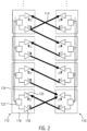
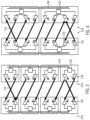
- FIG. 4 Alternative architectures which can also be advantageously used with the addressing scheme according to the present invention is depicted in figure 4 .
- the present invention of course can also be employed with systems that are optically unidirectional in that one of the optical units (reference numeral 210) only comprises optical senders and the other optical unit 210' comprises only receivers.
- each control unit 122 can be assigned to at least two emitters and/or receivers.
- FIG. 5 illustrates the optically unidirectional architecture.
- synchronization may happen between a first optical unit and a neighboring second optical unit of the same type and brand which, however, is not the one belonging to the intended protective field. Consequently, an unsafe condition may arise because the first optical unit may assume an uninterrupted light curtain while in reality the beam path between the first optical unit and the second optical unit is interrupted for instance by an intruding person.
- Such an erroneous synchronization may also happen with deflected beams that reach the first optical unit via mirroring surfaces.
- An example scenario may occur with a light curtain system being installed and running when a light emitter is pointed towards a receiver.
- this unintentionally involved other receiver might switch ON the output signal switching device, OSSD, which in the OFF state causes a control unit to output a safety signal upon interruption of at least one light barrier.
- OSSD output signal switching device
- the controllers 112 comprise storing means that store a unique identifier of the respective optical unit 102, 104.
- the unique identifier of the first optical unit 102 is transmitted to the second optical unit a 104 and stored in the controller 112.
- the unique identifier of the second optical unit 104 is transmitted to the first optical unit 102 and is stored by the controller 112 of the first optical unit 102.
- a factory fresh flag provides the information that this is the first power-up procedure after installation of the light curtain 100.
- This procedure of storing the respective identifier of the opposing optical unit is also referred to as "pairing" in the following.
- the controllers 112 exchange the respective unique identifiers and compare the received values with the values stored in the storing means during the first power-up procedure.
- the unique identifier which is received together with this erroneous signal is different to the identifier which is expected to be received. Consequently, the light curtain 100 may stop the power-up procedure and emit a warning signal.
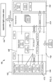
- Fig. 6 shows a more detailed block diagram of a light curtain 100 according to an exemplary embodiment of the present invention.
- the first optical unit 102 which may form a principal and the second optical unit 104 which may form a companion are structured essentially identical and differ from each other only in the configuration of their plug-in modules 106, 108.
- the optical unit 102 comprises an optical block 126 which symbolizes the plurality of optoelectronic components comprising the light emitting and light receiving elements.
- the top plug-in module 108 which is optional for the present invention may for instance comprise additional CPUs, inputs/outputs, and a supply delay.
- the bottom plug-in module 106 may exemplarily define the functionality of the first optical unit 102 as a principal comprising the OSSD.
- the optical unit 102 comprises a supply block 128 for managing the power supply and a CPU block 130 representing the control element of the optical unit 102.
- a bidirectional optical communication 134 takes place between the optical block 126 of the first optical unit 102 and the corresponding opposite light curtain stick 104.
- One or more DIP switches 132 are provided that allow a user to manually choose particular operational configurations. For instance, the setting of the DIP switch may indicate that an operational mode is to be used that employs beam coding.
- beam coding signifies an operational mode where the optical communication between the first optical unit 102 and the second optical unit 104 is performed using a particular defined optical pulse pattern.
- the first and second optical units 102, 104 have to use the same pulse pattern in order to be able to communicate with each other.
- the optical unit 102 may further comprise an optical alignment system (integrated laser alignment system, ILAS) and one or more light emitting diodes (LED) that are used for signaling purposes.
- An additional optical communication interface OCI may be provided for connecting the light curtain with an external device, such as a personal computer.
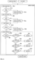
- Fig. 7 illustrates as a schematic flow chart the identification steps that are performed by each optical unit 102, 104 during a power-up procedure.
- the process starts with identifying the bottom plug-in module (step 701) and deciding whether the identification could be correctly established (step 702). If this identification did not take place properly, the process exits towards an error handling routine. If the answer is affirmative, it is decided, whether the plug-in module has been changed and replaced by a different type (step 703). If this is the case, an administration mode is entered (see Fig. 9 and the specification below). If, however, the plug-in type has not been changed, the DIP switches are read out in the next step (step 704).
- step 707 is to identify the top plug-in module. Only in case the top plug-in module also could be identified successfully (step 708), the process proceeds to the status that this particular stick has been identified (step 709). Otherwise, the process exits into the error handling routine.
- step 706 it is decided whether the present procedure is the first power-up procedure after delivery. If this is not the case, the administration mode is entered. However, if the reason for the DIP switch being changed is that it is the first power-up after delivery, the process proceeds to the identification of the top plug-in unit (step 707).
- the first and second optical units after having preformed their respective own identification start synchronizing with each other (step 802).
- the synchronization step is performed via the bidirectional optical communication 134 using the same beams that are also used for monitoring the protected area.
- step 803 it is decided for each of the two optical units whether the synchronization was successful or step 802 is repeated, if this is not the case. If the synchronization has been successful, the communication with the respective other stick is established in step 804. In step 805, it is determined whether the communication has been established successfully, and step 804 is repeated if this is not the case.
- step 806 the configurations of both sticks are compared to each other (step 806), and it is decided whether the configurations of the two sticks are identical (step 807). If this is the case, the process enters the run mode, which is the usual operation mode where the light curtain monitors a protected area.
- step 808 If the configuration is not identical, however, it is checked in step 808 whether the pairing between the two sticks has changed (step 808). If the pairing has changed, the process exits towards the administration mode (explained below with reference to Fig. 9 ). If the pairing has remained unchanged, however, the new configuration is distributed to all optoelectronic components in the optical unit (step 809). According to the present invention, step 808 is a safeguard against situations where a neighboring third stick erroneously succeeds to synchronize with one of the first and second sticks.
- Fig. 9 schematically illustrates the administration mode ("admin mode") that is entered when a user input is needed. In any case, entering the administration mode causes the OSSDs to be switched OFF.
- This mode may comprise different activities.
- the administration mode allows for diagnosis.
- Data are sent from the optical unit for instance to a computer when requested or permanently (steps 910 to 919). These data comprise for example operating data, configuration data or error data, e. g. length, resolution, product-ID number, production date, serial number, firmware, software, etc.
- the administration mode may comprise a configuration procedure and a firmware download mode. For these activities, data are sent for instance from a computer to the optical unit on request and new configuration sets or firmware are downloaded.
- a checking and possible teach-in procedure regarding the type of plug-in module can be performed (steps 901 to 903).
- a DIP switch confirmation can be performed (steps 904 to 906).
- changes in the position of the DIP switches are confirmed by a user.
- the pairing of the two optical units forming a light curtain is checked and confirmed in the administration mode (steps 907 to 909).
- the light curtain recognizes a new situation of the plug-in module (for example a new DIP switch setting)
- this new configuration must be confirmed by a user.
- This process can also be described as a teach-in of a new configuration.
- the principal stick which is configured as a receiver (“Rx stick”)
- Rx stick has a DIP switch to set the beam coding. Therefore, the user must validate the correct pairing of each system when beam coding is used, i.e. when the DIP switch for beam coding does not have the default position.
- the confirmation procedure may be used in both sticks, principal and companion, and may advantageously be performed as follows.
- the beam coding is changed using the appropriate DIP switch. Then, the system is installed and powered up; all other systems which could influence the confirmation process must be unpowered; at least some beams must be uninterrupted.
- the OSSD remain OFF in any case, i. e. whether the protective field is interrupted or not.
- the device IDs of the sticks are exchanged and paired automatically.
- a DIP switch confirmation procedure is required at the principal and the same confirmation procedure is required at the companion (if several systems are in the area, only one single companion, i.e. the associated and corresponding one, is allowed to confirm).
- the OSSD are switched ON.
- the procedure is performed via optical communication.
- the user may set the principal to beam coding (with confirming) and the principal stick sends the information about this setting via optical communication to the companion.
- the companion now may wait for a confirmation and the user confirms the setting at the companion.
- the companion sends the confirmation optically to the principal, which sends an acknowledge message to the companion. Only then the companion changes the beam coding and acknowledges it to principal. Both sticks are then ready for normal operation.
- this confirmation procedure may only be selected (performed) at the considered system - if other systems are installed nearby, such a confirmation must not be done.
- the correct pairing must be checked by the system (not by the user, but automatically) minimally at each power-up (i.e. the stick ID or cascaded unit ID are exchanged).
- a higher safety level can be achieved when doing it more often, for instance before activating the OSSD, when synchronizing the two sticks, and/or periodically during operation.
- Reference Numerals Reference Numeral Description 100 light curtain 102 first optical unit 104 second optical unit 106 first plug-in module 108 second plug-in module 110, 310 first optical module (without controller) 210, 410 optical module with only receivers 210', 410' optical module with only emitters 112 second optical module (with controller) 114 radiation beam 116 optoelectronic component 118 light emitting element 120 light receiving element 122 control element 124 communication bus 126 optical block 128 supply block 130 CPU block 132 DIP switches 134 bidirectional optical communication 701-709, 801-809, 901- process steps
Landscapes
- Physics & Mathematics (AREA)
- Life Sciences & Earth Sciences (AREA)
- General Life Sciences & Earth Sciences (AREA)
- General Physics & Mathematics (AREA)
- Geophysics (AREA)
- Optical Communication System (AREA)
Claims (13)
- Rideau de lumière pour surveiller un champ de protection, ledit rideau de lumière comprenant :au moins une première unité optique (102) comprenant au moins un premier émetteur de rayonnement et au moins un premier récepteur de rayonnement, et au moins une deuxième unité optique (104) qui est opposée à ladite première unité optique (102) comprenant au moins un deuxième récepteur de rayonnement et au moins un deuxième émetteur de rayonnement pour former un réseau linéaire de faisceaux de rayonnement entre les première et deuxième unités optiques (102, 104),ladite première unité optique (102) comprenant une première unité de commande et une première interface de communication, ladite deuxième unité optique (104) comprenant une deuxième unité de commande et une deuxième interface de communication,dans lequel un premier identifiant unique est attribué à la première unité optique (104) et un deuxième identifiant unique est attribué à la deuxième unité optique (102), etdans lequel les première et deuxième interfaces de communication peuvent fonctionner pour échanger des signaux de communication entre les première et deuxième unités optiques (102, 104),caractérisé en ce quechacune des première et deuxième unités de commande peut fonctionner pour vérifier l'identifiant de l'unité optique opposée sur la base des signaux de communication transmis, dans lequel les première et deuxième unités de commande peuvent en outre fonctionner, pendant une procédure de mise sous tension, pour déterminer si la procédure de mise sous tension est une première procédure de mise sous tension après l'installation,si la procédure de mise sous tension est une première procédure de mise sous tension après l'installation, pour stocker le premier identifiant unique dans la deuxième unité optique et/ou pour stocker le deuxième identifiant unique dans la première unité optique,si la procédure de mise sous tension n'est pas la première procédure de mise sous tension après l'installation, pour vérifier si les identifiants uniques de la/des première et/ou deuxième unité(s) optique(s) correspondent aux identifiants stockés.
- Rideau de lumière selon la revendication 1, dans lequel lesdites première et deuxième interfaces de communication sont formées par lesdits premiers et deuxièmes émetteurs de rayonnement et récepteurs de rayonnement.
- Rideau de lumière selon l'une des revendications précédentes, dans lequel lesdites première et deuxième unités optiques (102, 104) comprennent chacune une unité émettrice-réceptrice portant une pluralité d'éléments émetteurs de lumière et d'éléments récepteurs de lumière, lesdites première et deuxième unités émettrices-réceptrices ayant une structure identique.
- Rideau de lumière selon l'une des revendications précédentes, dans lequel chaque unité optique (102, 104) comprend un moyen de stockage pour stocker son propre identifiant unique et pour stocker l'identifiant unique de l'unité optique opposée.
- Procédé de fonctionnement d'un rideau de lumière ayant au moins une première unité optique (102) comprenant au moins un premier émetteur de rayonnement et au moins un premier récepteur de rayonnement, et au moins une deuxième unité optique (104) qui est opposée à ladite première unité optique comprenant au moins un deuxième récepteur de rayonnement et au moins un deuxième émetteur de rayonnement pour former un réseau linéaire de faisceaux de rayonnement entre les première et deuxième unités optique (102, 104), ladite première unité optique (102) comprenant une première unité de commande et une première interface de communication, ladite deuxième unité optique (104) comprenant une deuxième unité de commande et une deuxième interface de communication, ledit procédé étant caractérisé par les étapes suivantes :la transmission d'un premier identifiant unique attribué à la première unité optique vers la deuxième unité optique, et la transmission d'un deuxième identifiant unique attribué à la deuxième unité optique vers la première unité optique,la vérification que les identifiants uniques reçus des première et deuxième unités optiques correspondent à des identifiants qui sont stockés dans l'unité optique réceptrice,pendant une procédure de mise sous tension, la détermination que la procédure de mise sous tension est une première procédure de mise sous tension après l'installation,si la procédure de mise sous tension est une première procédure de mise sous tension après l'installation, le stockage du premier identifiant unique dans la deuxième unité optique et/ou le stockage du deuxième identifiant unique dans la première unité optique,si la procédure de mise sous tension n'est pas la première procédure de mise sous tension après l'installation, la vérification que les identifiants uniques de la/des première et/ou deuxième unité(s) optique(s) correspondent aux identifiants stockés.
- Procédé selon la revendication 5, dans lequel la procédure de mise sous tension est arrêtée, si les identifiants uniques des première et deuxième unités optiques ne correspondent pas aux identifiants stockés.
- Procédé selon la revendication 5 ou 6, dans lequel un drapeau est fourni qui indique un état dans lequel le rideau de lumière est fraîchement sorti de l'usine.
- Procédé selon la revendication 7, dans lequel, après une opération de maintenance, ledit drapeau peut être réinitialisé pour indiquer l'état dans lequel le rideau de lumière est fraîchement sorti de l'usine.
- Procédé selon l'une des revendications 5 à 8, dans lequel l'identifiant unique est en outre vérifié lors du fonctionnement continu du rideau de lumière.
- Procédé selon l'une des revendications 5 à 9, dans lequel lesdites première et deuxième unités optiques (102, 104) effectuent une communication optique bidirectionnelle entre elles.
- Procédé selon l'une des revendications 5 à 10, dans lequel lesdits premier et deuxième identifiants uniques comprennent un mot binaire.
- Procédé selon l'une des revendications 5 à 11, dans lequel ledit au moins un faisceau de rayonnement est formé par un rayonnement pulsé, et dans lequel un motif d'impulsion dudit faisceau de rayonnement peut être choisi comme un codage de faisceau qui est spécifique au rideau de lumière.
- Procédé selon la revendication 12, dans lequel, si le rideau de lumière fonctionne en utilisant ledit codage de faisceau, un utilisateur doit valider un appairage correct des unités optiques du rideau de lumière.
Priority Applications (1)
| Application Number | Priority Date | Filing Date | Title |
|---|---|---|---|
| EP18157097.9A EP3528014B1 (fr) | 2018-02-16 | 2018-02-16 | Rideau de lumière et procédé d'exploitation d'un rideau de lumière |
Applications Claiming Priority (1)
| Application Number | Priority Date | Filing Date | Title |
|---|---|---|---|
| EP18157097.9A EP3528014B1 (fr) | 2018-02-16 | 2018-02-16 | Rideau de lumière et procédé d'exploitation d'un rideau de lumière |
Publications (2)
| Publication Number | Publication Date |
|---|---|
| EP3528014A1 EP3528014A1 (fr) | 2019-08-21 |
| EP3528014B1 true EP3528014B1 (fr) | 2023-05-03 |
Family
ID=61244395
Family Applications (1)
| Application Number | Title | Priority Date | Filing Date |
|---|---|---|---|
| EP18157097.9A Active EP3528014B1 (fr) | 2018-02-16 | 2018-02-16 | Rideau de lumière et procédé d'exploitation d'un rideau de lumière |
Country Status (1)
| Country | Link |
|---|---|
| EP (1) | EP3528014B1 (fr) |
Citations (1)
| Publication number | Priority date | Publication date | Assignee | Title |
|---|---|---|---|---|
| EP2796903A1 (fr) * | 2013-04-24 | 2014-10-29 | Cedes Safety & Automation AG | Unité optique, rideau de lumière et procédé pour attribuer une adresse individuelle |
Family Cites Families (5)
| Publication number | Priority date | Publication date | Assignee | Title |
|---|---|---|---|---|
| FR2778749B1 (fr) * | 1998-05-15 | 2000-07-28 | Jay Electronique Sa | Barriere optique formee d'elements emetteurs/recepteurs regroupes en mobiles |
| DE10046136B4 (de) * | 2000-09-15 | 2006-04-20 | Leuze Lumiflex Gmbh + Co. Kg | Verfahren zur Identifizierung von Lichtschrankensendern |
| EP1870734B1 (fr) | 2006-06-20 | 2009-01-14 | Sick Ag | Rideau de lumière opto-électronique avec au moins deux barres de transmission/réception |
| EP2511737B1 (fr) | 2011-04-13 | 2021-09-15 | Rockwell Automation Switzerland GmbH | Rideau de lumière modulaire et module de plugin correspondant |
| EP2813868B1 (fr) | 2013-06-11 | 2021-08-04 | Rockwell Automation Switzerland GmbH | Procédé de synchronisation d'unités optiques d'une barrière photoélectrique et rideau de lumière |
-
2018
- 2018-02-16 EP EP18157097.9A patent/EP3528014B1/fr active Active
Patent Citations (1)
| Publication number | Priority date | Publication date | Assignee | Title |
|---|---|---|---|---|
| EP2796903A1 (fr) * | 2013-04-24 | 2014-10-29 | Cedes Safety & Automation AG | Unité optique, rideau de lumière et procédé pour attribuer une adresse individuelle |
Also Published As
| Publication number | Publication date |
|---|---|
| EP3528014A1 (fr) | 2019-08-21 |
Similar Documents
| Publication | Publication Date | Title |
|---|---|---|
| US8058605B2 (en) | Optoelectronic sensor for safeguarding a hazardous area | |
| EP0598630B1 (fr) | Rideau de lumière avec des indicateurs pour les faisceaux individuels et méthode d'opération | |
| US10178302B2 (en) | Safety control device and safety control system | |
| EP2511737B1 (fr) | Rideau de lumière modulaire et module de plugin correspondant | |
| US6137408A (en) | Controller for plural area sensors | |
| EP2813868B1 (fr) | Procédé de synchronisation d'unités optiques d'une barrière photoélectrique et rideau de lumière | |
| US8487236B2 (en) | Multi-optical axis photoelectric sensor | |
| JPH11345548A (ja) | 多光軸光電スイッチの状態表示方法およびその多光軸光電スイッチ | |
| ES2361858T3 (es) | Sistema de detección y procedimiento de detección. | |
| CN105371094B (zh) | 多光轴光电传感器 | |
| US20070200699A1 (en) | Light barrier arrangement | |
| ES2783349T3 (es) | Dispositivo de supervisión para una instalación de transporte de personas, método de prueba e instalación de transporte de personas | |
| EP2808706A1 (fr) | Élément émetteur/récepteur pour une unité optique d'une barrière photoélectrique et rideau de lumière photoélectrique | |
| US11262475B2 (en) | Optoelectronic sensor having plug-in unit for providing extended functionality | |
| EP2383623B1 (fr) | Système modulaire de dispositif de commutation sécurisée avec liaison optique | |
| JP2006317238A (ja) | 多光軸光電式安全装置 | |
| JP2006317237A (ja) | 多光軸光電式安全装置 | |
| WO1998010516A1 (fr) | Procede de controle general des operations et controleur associe | |
| EP3528014B1 (fr) | Rideau de lumière et procédé d'exploitation d'un rideau de lumière | |
| JP2013156813A (ja) | 侵入検出装置,ロボット,侵入検出方法および侵入検出プログラム | |
| CN111094164A (zh) | 与建筑物相关的人员运送系统的现场设备的状态检查 | |
| JP5813982B2 (ja) | 双方向型物体検知センサ | |
| CN1828118B (zh) | 具有单独的输出信号的光电栅栏 | |
| US6204575B1 (en) | Method of verifying an extension area sensor controlled, master controller of area sensors, and cover to be used when no slave controller is added | |
| US12228696B1 (en) | Sensor arrangement |
Legal Events
| Date | Code | Title | Description |
|---|---|---|---|
| PUAI | Public reference made under article 153(3) epc to a published international application that has entered the european phase |
Free format text: ORIGINAL CODE: 0009012 |
|
| STAA | Information on the status of an ep patent application or granted ep patent |
Free format text: STATUS: THE APPLICATION HAS BEEN PUBLISHED |
|
| AK | Designated contracting states |
Kind code of ref document: A1 Designated state(s): AL AT BE BG CH CY CZ DE DK EE ES FI FR GB GR HR HU IE IS IT LI LT LU LV MC MK MT NL NO PL PT RO RS SE SI SK SM TR |
|
| AX | Request for extension of the european patent |
Extension state: BA ME |
|
| STAA | Information on the status of an ep patent application or granted ep patent |
Free format text: STATUS: REQUEST FOR EXAMINATION WAS MADE |
|
| 17P | Request for examination filed |
Effective date: 20200218 |
|
| RBV | Designated contracting states (corrected) |
Designated state(s): AL AT BE BG CH CY CZ DE DK EE ES FI FR GB GR HR HU IE IS IT LI LT LU LV MC MK MT NL NO PL PT RO RS SE SI SK SM TR |
|
| STAA | Information on the status of an ep patent application or granted ep patent |
Free format text: STATUS: EXAMINATION IS IN PROGRESS |
|
| 17Q | First examination report despatched |
Effective date: 20220331 |
|
| GRAP | Despatch of communication of intention to grant a patent |
Free format text: ORIGINAL CODE: EPIDOSNIGR1 |
|
| STAA | Information on the status of an ep patent application or granted ep patent |
Free format text: STATUS: GRANT OF PATENT IS INTENDED |
|
| INTG | Intention to grant announced |
Effective date: 20230130 |
|
| GRAS | Grant fee paid |
Free format text: ORIGINAL CODE: EPIDOSNIGR3 |
|
| GRAA | (expected) grant |
Free format text: ORIGINAL CODE: 0009210 |
|
| STAA | Information on the status of an ep patent application or granted ep patent |
Free format text: STATUS: THE PATENT HAS BEEN GRANTED |
|
| AK | Designated contracting states |
Kind code of ref document: B1 Designated state(s): AL AT BE BG CH CY CZ DE DK EE ES FI FR GB GR HR HU IE IS IT LI LT LU LV MC MK MT NL NO PL PT RO RS SE SI SK SM TR |
|
| REG | Reference to a national code |
Ref country code: GB Ref legal event code: FG4D |
|
| REG | Reference to a national code |
Ref country code: AT Ref legal event code: REF Ref document number: 1565097 Country of ref document: AT Kind code of ref document: T Effective date: 20230515 Ref country code: CH Ref legal event code: EP |
|
| REG | Reference to a national code |
Ref country code: DE Ref legal event code: R096 Ref document number: 602018049097 Country of ref document: DE |
|
| REG | Reference to a national code |
Ref country code: IE Ref legal event code: FG4D |
|
| REG | Reference to a national code |
Ref country code: LT Ref legal event code: MG9D |
|
| REG | Reference to a national code |
Ref country code: NL Ref legal event code: MP Effective date: 20230503 |
|
| REG | Reference to a national code |
Ref country code: AT Ref legal event code: MK05 Ref document number: 1565097 Country of ref document: AT Kind code of ref document: T Effective date: 20230503 |
|
| PG25 | Lapsed in a contracting state [announced via postgrant information from national office to epo] |
Ref country code: SE Free format text: LAPSE BECAUSE OF FAILURE TO SUBMIT A TRANSLATION OF THE DESCRIPTION OR TO PAY THE FEE WITHIN THE PRESCRIBED TIME-LIMIT Effective date: 20230503 Ref country code: PT Free format text: LAPSE BECAUSE OF FAILURE TO SUBMIT A TRANSLATION OF THE DESCRIPTION OR TO PAY THE FEE WITHIN THE PRESCRIBED TIME-LIMIT Effective date: 20230904 Ref country code: NO Free format text: LAPSE BECAUSE OF FAILURE TO SUBMIT A TRANSLATION OF THE DESCRIPTION OR TO PAY THE FEE WITHIN THE PRESCRIBED TIME-LIMIT Effective date: 20230803 Ref country code: NL Free format text: LAPSE BECAUSE OF FAILURE TO SUBMIT A TRANSLATION OF THE DESCRIPTION OR TO PAY THE FEE WITHIN THE PRESCRIBED TIME-LIMIT Effective date: 20230503 Ref country code: ES Free format text: LAPSE BECAUSE OF FAILURE TO SUBMIT A TRANSLATION OF THE DESCRIPTION OR TO PAY THE FEE WITHIN THE PRESCRIBED TIME-LIMIT Effective date: 20230503 Ref country code: AT Free format text: LAPSE BECAUSE OF FAILURE TO SUBMIT A TRANSLATION OF THE DESCRIPTION OR TO PAY THE FEE WITHIN THE PRESCRIBED TIME-LIMIT Effective date: 20230503 |
|
| PG25 | Lapsed in a contracting state [announced via postgrant information from national office to epo] |
Ref country code: RS Free format text: LAPSE BECAUSE OF FAILURE TO SUBMIT A TRANSLATION OF THE DESCRIPTION OR TO PAY THE FEE WITHIN THE PRESCRIBED TIME-LIMIT Effective date: 20230503 Ref country code: PL Free format text: LAPSE BECAUSE OF FAILURE TO SUBMIT A TRANSLATION OF THE DESCRIPTION OR TO PAY THE FEE WITHIN THE PRESCRIBED TIME-LIMIT Effective date: 20230503 Ref country code: LV Free format text: LAPSE BECAUSE OF FAILURE TO SUBMIT A TRANSLATION OF THE DESCRIPTION OR TO PAY THE FEE WITHIN THE PRESCRIBED TIME-LIMIT Effective date: 20230503 Ref country code: LT Free format text: LAPSE BECAUSE OF FAILURE TO SUBMIT A TRANSLATION OF THE DESCRIPTION OR TO PAY THE FEE WITHIN THE PRESCRIBED TIME-LIMIT Effective date: 20230503 Ref country code: IS Free format text: LAPSE BECAUSE OF FAILURE TO SUBMIT A TRANSLATION OF THE DESCRIPTION OR TO PAY THE FEE WITHIN THE PRESCRIBED TIME-LIMIT Effective date: 20230903 Ref country code: HR Free format text: LAPSE BECAUSE OF FAILURE TO SUBMIT A TRANSLATION OF THE DESCRIPTION OR TO PAY THE FEE WITHIN THE PRESCRIBED TIME-LIMIT Effective date: 20230503 Ref country code: GR Free format text: LAPSE BECAUSE OF FAILURE TO SUBMIT A TRANSLATION OF THE DESCRIPTION OR TO PAY THE FEE WITHIN THE PRESCRIBED TIME-LIMIT Effective date: 20230804 |
|
| PG25 | Lapsed in a contracting state [announced via postgrant information from national office to epo] |
Ref country code: FI Free format text: LAPSE BECAUSE OF FAILURE TO SUBMIT A TRANSLATION OF THE DESCRIPTION OR TO PAY THE FEE WITHIN THE PRESCRIBED TIME-LIMIT Effective date: 20230503 |
|
| PG25 | Lapsed in a contracting state [announced via postgrant information from national office to epo] |
Ref country code: SK Free format text: LAPSE BECAUSE OF FAILURE TO SUBMIT A TRANSLATION OF THE DESCRIPTION OR TO PAY THE FEE WITHIN THE PRESCRIBED TIME-LIMIT Effective date: 20230503 |
|
| PG25 | Lapsed in a contracting state [announced via postgrant information from national office to epo] |
Ref country code: SM Free format text: LAPSE BECAUSE OF FAILURE TO SUBMIT A TRANSLATION OF THE DESCRIPTION OR TO PAY THE FEE WITHIN THE PRESCRIBED TIME-LIMIT Effective date: 20230503 Ref country code: SK Free format text: LAPSE BECAUSE OF FAILURE TO SUBMIT A TRANSLATION OF THE DESCRIPTION OR TO PAY THE FEE WITHIN THE PRESCRIBED TIME-LIMIT Effective date: 20230503 Ref country code: RO Free format text: LAPSE BECAUSE OF FAILURE TO SUBMIT A TRANSLATION OF THE DESCRIPTION OR TO PAY THE FEE WITHIN THE PRESCRIBED TIME-LIMIT Effective date: 20230503 Ref country code: EE Free format text: LAPSE BECAUSE OF FAILURE TO SUBMIT A TRANSLATION OF THE DESCRIPTION OR TO PAY THE FEE WITHIN THE PRESCRIBED TIME-LIMIT Effective date: 20230503 Ref country code: DK Free format text: LAPSE BECAUSE OF FAILURE TO SUBMIT A TRANSLATION OF THE DESCRIPTION OR TO PAY THE FEE WITHIN THE PRESCRIBED TIME-LIMIT Effective date: 20230503 Ref country code: CZ Free format text: LAPSE BECAUSE OF FAILURE TO SUBMIT A TRANSLATION OF THE DESCRIPTION OR TO PAY THE FEE WITHIN THE PRESCRIBED TIME-LIMIT Effective date: 20230503 |
|
| REG | Reference to a national code |
Ref country code: DE Ref legal event code: R097 Ref document number: 602018049097 Country of ref document: DE |
|
| PLBE | No opposition filed within time limit |
Free format text: ORIGINAL CODE: 0009261 |
|
| STAA | Information on the status of an ep patent application or granted ep patent |
Free format text: STATUS: NO OPPOSITION FILED WITHIN TIME LIMIT |
|
| 26N | No opposition filed |
Effective date: 20240206 |
|
| PG25 | Lapsed in a contracting state [announced via postgrant information from national office to epo] |
Ref country code: SI Free format text: LAPSE BECAUSE OF FAILURE TO SUBMIT A TRANSLATION OF THE DESCRIPTION OR TO PAY THE FEE WITHIN THE PRESCRIBED TIME-LIMIT Effective date: 20230503 |
|
| PG25 | Lapsed in a contracting state [announced via postgrant information from national office to epo] |
Ref country code: SI Free format text: LAPSE BECAUSE OF FAILURE TO SUBMIT A TRANSLATION OF THE DESCRIPTION OR TO PAY THE FEE WITHIN THE PRESCRIBED TIME-LIMIT Effective date: 20230503 Ref country code: IT Free format text: LAPSE BECAUSE OF FAILURE TO SUBMIT A TRANSLATION OF THE DESCRIPTION OR TO PAY THE FEE WITHIN THE PRESCRIBED TIME-LIMIT Effective date: 20230503 |
|
| PG25 | Lapsed in a contracting state [announced via postgrant information from national office to epo] |
Ref country code: MC Free format text: LAPSE BECAUSE OF FAILURE TO SUBMIT A TRANSLATION OF THE DESCRIPTION OR TO PAY THE FEE WITHIN THE PRESCRIBED TIME-LIMIT Effective date: 20230503 |
|
| REG | Reference to a national code |
Ref country code: CH Ref legal event code: PL |
|
| PG25 | Lapsed in a contracting state [announced via postgrant information from national office to epo] |
Ref country code: LU Free format text: LAPSE BECAUSE OF NON-PAYMENT OF DUE FEES Effective date: 20240216 |
|
| PG25 | Lapsed in a contracting state [announced via postgrant information from national office to epo] |
Ref country code: CH Free format text: LAPSE BECAUSE OF NON-PAYMENT OF DUE FEES Effective date: 20240229 |
|
| PG25 | Lapsed in a contracting state [announced via postgrant information from national office to epo] |
Ref country code: LU Free format text: LAPSE BECAUSE OF NON-PAYMENT OF DUE FEES Effective date: 20240216 Ref country code: CH Free format text: LAPSE BECAUSE OF NON-PAYMENT OF DUE FEES Effective date: 20240229 |
|
| PG25 | Lapsed in a contracting state [announced via postgrant information from national office to epo] |
Ref country code: BG Free format text: LAPSE BECAUSE OF FAILURE TO SUBMIT A TRANSLATION OF THE DESCRIPTION OR TO PAY THE FEE WITHIN THE PRESCRIBED TIME-LIMIT Effective date: 20230503 |
|
| PG25 | Lapsed in a contracting state [announced via postgrant information from national office to epo] |
Ref country code: BG Free format text: LAPSE BECAUSE OF FAILURE TO SUBMIT A TRANSLATION OF THE DESCRIPTION OR TO PAY THE FEE WITHIN THE PRESCRIBED TIME-LIMIT Effective date: 20230503 |
|
| REG | Reference to a national code |
Ref country code: BE Ref legal event code: MM Effective date: 20240229 |
|
| PG25 | Lapsed in a contracting state [announced via postgrant information from national office to epo] |
Ref country code: BE Free format text: LAPSE BECAUSE OF NON-PAYMENT OF DUE FEES Effective date: 20240229 |
|
| PG25 | Lapsed in a contracting state [announced via postgrant information from national office to epo] |
Ref country code: IE Free format text: LAPSE BECAUSE OF NON-PAYMENT OF DUE FEES Effective date: 20240216 |
|
| PG25 | Lapsed in a contracting state [announced via postgrant information from national office to epo] |
Ref country code: IE Free format text: LAPSE BECAUSE OF NON-PAYMENT OF DUE FEES Effective date: 20240216 Ref country code: BE Free format text: LAPSE BECAUSE OF NON-PAYMENT OF DUE FEES Effective date: 20240229 |
|
| PG25 | Lapsed in a contracting state [announced via postgrant information from national office to epo] |
Ref country code: CY Free format text: LAPSE BECAUSE OF FAILURE TO SUBMIT A TRANSLATION OF THE DESCRIPTION OR TO PAY THE FEE WITHIN THE PRESCRIBED TIME-LIMIT; INVALID AB INITIO Effective date: 20180216 |
|
| PG25 | Lapsed in a contracting state [announced via postgrant information from national office to epo] |
Ref country code: HU Free format text: LAPSE BECAUSE OF FAILURE TO SUBMIT A TRANSLATION OF THE DESCRIPTION OR TO PAY THE FEE WITHIN THE PRESCRIBED TIME-LIMIT; INVALID AB INITIO Effective date: 20180216 |
|
| PG25 | Lapsed in a contracting state [announced via postgrant information from national office to epo] |
Ref country code: TR Free format text: LAPSE BECAUSE OF FAILURE TO SUBMIT A TRANSLATION OF THE DESCRIPTION OR TO PAY THE FEE WITHIN THE PRESCRIBED TIME-LIMIT Effective date: 20230503 |
|
| PGFP | Annual fee paid to national office [announced via postgrant information from national office to epo] |
Ref country code: GB Payment date: 20260122 Year of fee payment: 9 |
|
| PGFP | Annual fee paid to national office [announced via postgrant information from national office to epo] |
Ref country code: DE Payment date: 20260121 Year of fee payment: 9 |
|
| PGFP | Annual fee paid to national office [announced via postgrant information from national office to epo] |
Ref country code: FR Payment date: 20260121 Year of fee payment: 9 |