EP3528044B1 - Dispositif de projection - Google Patents
Dispositif de projection Download PDFInfo
- Publication number
- EP3528044B1 EP3528044B1 EP19156686.8A EP19156686A EP3528044B1 EP 3528044 B1 EP3528044 B1 EP 3528044B1 EP 19156686 A EP19156686 A EP 19156686A EP 3528044 B1 EP3528044 B1 EP 3528044B1
- Authority
- EP
- European Patent Office
- Prior art keywords
- light
- color
- combining element
- splitting
- projection device
- Prior art date
- Legal status (The legal status is an assumption and is not a legal conclusion. Google has not performed a legal analysis and makes no representation as to the accuracy of the status listed.)
- Active
Links
Images


Classifications
-
- G—PHYSICS
- G03—PHOTOGRAPHY; CINEMATOGRAPHY; ANALOGOUS TECHNIQUES USING WAVES OTHER THAN OPTICAL WAVES; ELECTROGRAPHY; HOLOGRAPHY
- G03B—APPARATUS OR ARRANGEMENTS FOR TAKING PHOTOGRAPHS OR FOR PROJECTING OR VIEWING THEM; APPARATUS OR ARRANGEMENTS EMPLOYING ANALOGOUS TECHNIQUES USING WAVES OTHER THAN OPTICAL WAVES; ACCESSORIES THEREFOR
- G03B33/00—Colour photography, other than mere exposure or projection of a colour film
- G03B33/10—Simultaneous recording or projection
- G03B33/12—Simultaneous recording or projection using beam-splitting or beam-combining systems, e.g. dichroic mirrors
-
- G—PHYSICS
- G02—OPTICS
- G02B—OPTICAL ELEMENTS, SYSTEMS OR APPARATUS
- G02B27/00—Optical systems or apparatus not provided for by any of the groups G02B1/00 - G02B26/00, G02B30/00
- G02B27/10—Beam splitting or combining systems
- G02B27/1006—Beam splitting or combining systems for splitting or combining different wavelengths
-
- G—PHYSICS
- G02—OPTICS
- G02B—OPTICAL ELEMENTS, SYSTEMS OR APPARATUS
- G02B27/00—Optical systems or apparatus not provided for by any of the groups G02B1/00 - G02B26/00, G02B30/00
- G02B27/10—Beam splitting or combining systems
- G02B27/14—Beam splitting or combining systems operating by reflection only
- G02B27/141—Beam splitting or combining systems operating by reflection only using dichroic mirrors
-
- G—PHYSICS
- G03—PHOTOGRAPHY; CINEMATOGRAPHY; ANALOGOUS TECHNIQUES USING WAVES OTHER THAN OPTICAL WAVES; ELECTROGRAPHY; HOLOGRAPHY
- G03B—APPARATUS OR ARRANGEMENTS FOR TAKING PHOTOGRAPHS OR FOR PROJECTING OR VIEWING THEM; APPARATUS OR ARRANGEMENTS EMPLOYING ANALOGOUS TECHNIQUES USING WAVES OTHER THAN OPTICAL WAVES; ACCESSORIES THEREFOR
- G03B21/00—Projectors or projection-type viewers; Accessories therefor
- G03B21/005—Projectors using an electronic spatial light modulator but not peculiar thereto
-
- G—PHYSICS
- G03—PHOTOGRAPHY; CINEMATOGRAPHY; ANALOGOUS TECHNIQUES USING WAVES OTHER THAN OPTICAL WAVES; ELECTROGRAPHY; HOLOGRAPHY
- G03B—APPARATUS OR ARRANGEMENTS FOR TAKING PHOTOGRAPHS OR FOR PROJECTING OR VIEWING THEM; APPARATUS OR ARRANGEMENTS EMPLOYING ANALOGOUS TECHNIQUES USING WAVES OTHER THAN OPTICAL WAVES; ACCESSORIES THEREFOR
- G03B21/00—Projectors or projection-type viewers; Accessories therefor
- G03B21/14—Details
- G03B21/20—Lamp housings
- G03B21/2006—Lamp housings characterised by the light source
- G03B21/2033—LED or laser light sources
-
- G—PHYSICS
- G03—PHOTOGRAPHY; CINEMATOGRAPHY; ANALOGOUS TECHNIQUES USING WAVES OTHER THAN OPTICAL WAVES; ELECTROGRAPHY; HOLOGRAPHY
- G03B—APPARATUS OR ARRANGEMENTS FOR TAKING PHOTOGRAPHS OR FOR PROJECTING OR VIEWING THEM; APPARATUS OR ARRANGEMENTS EMPLOYING ANALOGOUS TECHNIQUES USING WAVES OTHER THAN OPTICAL WAVES; ACCESSORIES THEREFOR
- G03B21/00—Projectors or projection-type viewers; Accessories therefor
- G03B21/14—Details
- G03B21/20—Lamp housings
- G03B21/206—Control of light source other than position or intensity
-
- G—PHYSICS
- G03—PHOTOGRAPHY; CINEMATOGRAPHY; ANALOGOUS TECHNIQUES USING WAVES OTHER THAN OPTICAL WAVES; ELECTROGRAPHY; HOLOGRAPHY
- G03B—APPARATUS OR ARRANGEMENTS FOR TAKING PHOTOGRAPHS OR FOR PROJECTING OR VIEWING THEM; APPARATUS OR ARRANGEMENTS EMPLOYING ANALOGOUS TECHNIQUES USING WAVES OTHER THAN OPTICAL WAVES; ACCESSORIES THEREFOR
- G03B21/00—Projectors or projection-type viewers; Accessories therefor
- G03B21/14—Details
- G03B21/20—Lamp housings
- G03B21/2066—Reflectors in illumination beam
-
- G—PHYSICS
- G03—PHOTOGRAPHY; CINEMATOGRAPHY; ANALOGOUS TECHNIQUES USING WAVES OTHER THAN OPTICAL WAVES; ELECTROGRAPHY; HOLOGRAPHY
- G03B—APPARATUS OR ARRANGEMENTS FOR TAKING PHOTOGRAPHS OR FOR PROJECTING OR VIEWING THEM; APPARATUS OR ARRANGEMENTS EMPLOYING ANALOGOUS TECHNIQUES USING WAVES OTHER THAN OPTICAL WAVES; ACCESSORIES THEREFOR
- G03B21/00—Projectors or projection-type viewers; Accessories therefor
- G03B21/14—Details
- G03B21/20—Lamp housings
- G03B21/208—Homogenising, shaping of the illumination light
Definitions
- the disclosure is related to a projection device, and particularly to an illumination system and a projection device with simple structure.
- the structure of a projection device such as a laser projector, is provided with at least two dichroic mirrors having opposite coating conditions to arrange the optical path for different color light.
- the dichroic mirrors with opposite coating conditions cause the beam of projection device to consume more energy in the transmission process.
- there are limits to reduction of the volume of such structure the manufacturing process of the mechanical element is complex and the required accuracy is higher.
- BACKGROUND section is only for enhancement of understanding of the BACKGROUND section of the described technology and therefore it may contain information that does not form the prior art that is already known to a person of ordinary skill in the art. Further, the information disclosed in the BACKGROUND section does not mean that one or more problems to be resolved by one or more embodiments of the disclosure was acknowledged by a person of ordinary skill in the art.
- US 2005/062614 A1 describes a projection display apparatus which includes a light source configured to supply light; a polarizing beam splitter for splitting light from the light source into two different polarization state lights; two reflective light panels of which each has a color filter embedded therein and respectively modulates the two polarization state lights so as to simultaneously produce red, green and blue image lights; and a projection lens receiving these color image lights and then projecting them onto a viewing surface so as to form a full-color image.
- An embodiment of the disclosure provides a projection device having the advantage of simple structure, which can reduce the volume of structure while reducing power consumption of the projection device, thereby improving compactness and optical efficiency of the projection device.
- an embodiment of the disclosure provides a projection device including an illumination system, a light splitting and combining element, at least two light valves and an image-forming lens.
- the illumination system is configured to provide an illumination beam.
- the illumination beam includes a first color light and a second color light.
- the light splitting and combining element is disposed on a transmission path of the illumination beam to allow the first color light to pass through and reflect the second color light.
- the at least two light valves are respectively disposed on a transmission path of the first color light and the second color light from the light splitting and combining element to respectively convert the first color light and the second color light into a first color image light and a second color image light.
- the image-forming lens is disposed on a transmission path of the first color image light and the second color image light from the at least two light valves, and receives the first color image light and the second color image light to generate a projection beam, wherein the first color image light from the first color light passes through the light splitting and combining element to the image-forming lens, and the second color image light from the second beam is reflected by the light splitting and combining element to the image-forming lens.
- the projection device further comprises at least two reflecting elements respectively disposed on the transmission paths of the first color light and the second color light from the light splitting and combining element, and configured to respectively reflect the first color light and the second color light to the at least two light valves.
- a transmission direction of the first color image light and the second color image light between the light splitting and combining element and the image-forming lens is parallel with and opposite to a transmission direction of the illumination beam between the illumination system and the light splitting and combining element.
- the illumination system and the image-forming lens are disposed on the same side of the light splitting and combining element.
- the light splitting and combining element comprises a first region and a second region adjacent to each other, the illumination beam from the illumination system enters the first region of the light splitting and combining element, the first color image light and the second color image light from the at least two light valves enter the second region of the light splitting and combining element.
- an alignment direction of the first region and the second region is perpendicular to a transmission direction of the illumination beam between the illumination system and the light splitting and combining element, and the alignment direction of the first region and the second region is perpendicular to a transmission direction of the first color image light and the second color image light between the light splitting and combining element and the image-forming lens.
- the projection device further comprises at least two reflecting elements respectively disposed on the transmission paths of the first color light and the second color light from the light splitting and combining element, and the at least two reflecting elements respectively reflect the first color light and the second color light from the first region to the at least two light valves.
- the projection device further comprises a first prism set and a second prism set, wherein the first prism set is disposed on the transmission path of the first color light and having a first surface, a second surface and a third surface, the first color light reflected by one of the at least two reflecting elements enters the first prism set through the first surface, and is transmitted to one of the at least two light valves after leaving through the second surface, wherein the first color image light enters the first prism set through the second surface, and is transmitted to the second region of the light splitting and combining element after leaving through the third surface; and the second prism set is disposed on the transmission path of the second color light and having a fourth surface, a fifth surface and a sixth surface, the second color light reflected by the other one of the at least two reflecting elements enters the second prism set through the fourth surface, and is transmitted to the other one of the at least two light valves after leaving through the fifth surface, wherein the second color image light enters the second prism set through the fifth surface, and is transmitted
- the illumination beam further comprises a third color light.
- the light splitting and combining element allows the third color light to pass through, a transmission path of the third color light from the light splitting and combining element is the same as that of the first color light.
- the light splitting and combining element reflects the third color light, and a transmission path of the third color light from the light splitting and combining element is the same as that of the second color light.
- the illumination system comprises a light integration rod, wherein the light integration rod is disposed on the transmission path of the illumination beam, and the illumination beam is transmitted to the light splitting and combining element after passing through the light integration rod.
- the projection device further comprises two filters, wherein the two filters are respectively disposed on transmission paths of the first color light and the second color light, and are respectively disposed between the light splitting and combining element and the at least two light valves.
- the illumination system comprises a lens array module, wherein the lens array module is disposed on the transmission path of the illumination beam, and the illumination beam is transmitted to the light splitting and combining element after passing through the lens array module.
- the number of light splitting and combining element required by the projection device may be reduced, such that it is possible to use only the structure of a single light splitting and combining element and thus achieving simple structure.
- the mechanical element can be easily designed and assembled while the volume of projection device can be minimized. Additionally, it is not required to use different coatings and thus the power consumption of the projection device can be reduced, thereby improving compactness and optical efficiency of the projection device and reducing manufacturing cost.
- FIG. 1 is a schematic view of a projection device from a perspective according to an embodiment of the disclosure.
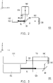
- FIG. 2 is a schematic top view of a projection device according to the embodiment of FIG. 1 of the disclosure.
- FIG. 3 is a schematic side view of the projection device according to the embodiment of FIG. 1 of the disclosure.
- a projection device 100 includes an illumination system 110, a light splitting and combining element 120, at least two reflecting elements such as a reflecting element M1 and a reflecting element M2, at least two light valves such as a light valve 130 and a light valve 140 and an image-forming lens 150.
- the illumination system 110 is configured to provide an illumination beam IL, wherein the illumination beam IL includes a first color light R and a second color light G.
- the light splitting and combining element 120 is disposed on a transmission path of the illumination beam IL. After the illumination beam IL is transmitted to the light splitting and combining element 120, the light splitting and combining element 120 splits the illumination beam IL into the first color light R and the second color light G, that is, the light splitting and combining element 120 allows the first color light R to pass through and reflects the second color light G.
- the illumination beam IL may be a yellow beam
- the first color light R may be a red beam
- the second color light G may be a green beam; that is, the yellow beam at least includes beams having red wavelength band and green wavelength band, which should not be construed as a limitation to the disclosure.
- the reflecting element M1 and the reflecting element M2 are configured to reflect an incident beam, and respectively disposed on transmission paths of the first color light R and the second color light G from the light splitting and combining element 120 so as to change the transmission directions of the first color light R and the second color light G.
- the light valve 130 is disposed on a transmission path of the first color light R reflected by the reflecting element M1, and converts the reflected first color light R into a first color image light IB1.
- the light valve 140 is disposed on a transmission path of the second color light G reflected by the reflecting element M2, and converts the reflected second color light G into a second color image light IB2.
- the projection device 100 of the embodiment further includes a first prism set 160 and a second prism set 170.
- the first prism set 160 and the second prism set 170 having one or more prisms are configured to control the transmission path of the beam or split the beam.
- the first prism set 160 is disposed on a transmission path of the first color light R between the reflecting element M1 and the light valve 130.
- the second prism set 170 is disposed on a transmission path of the second color light G between the reflecting element M2 and the light valve 140.
- the first color light R enters the first prism set 160 through a surface S1 (i.e., first surface) after being reflected by the reflecting element M1, leaves the first prism set 160 through a surface S2 (i.e., second surface) and is transmitted to the light valve 130 to be converted by the light valve 130 into the first color image light IB1. Then the first color image light IB1 enters the first prism set 160 through the surface S2, and is transmitted to the light splitting and combining element 120 after leaving the first prism set 160 through a surface S3 (i.e., third surface).
- a surface S1 i.e., first surface
- S2 i.e., second surface
- the first color image light IB1 enters the first prism set 160 through the surface S2, and is transmitted to the light splitting and combining element 120 after leaving the first prism set 160 through a surface S3 (i.e., third surface).
- the second color light G enters the second prism set 170 through a surface S4 (i.e., fourth surface) after being reflected by the reflecting element M2, and is transmitted to the light valve 140 after leaving the second prism set 170 through a surface S5 (i.e., fifth surface) to be converted by the light valve 140 into the second color image light IB2. Then the second color image light IB2 enters the second prism set 170 through the surface S5 and leaves the second prism set 170 through a surface S6 (i.e., sixth surface) to be transmitted to the light splitting and combining element 120.
- a surface S4 i.e., fourth surface
- a surface S5 i.e., fifth surface
- the image-forming lens 150 is disposed on a transmission path of the first color image light IB1 from the light valve 130 and the second color image light IB2 from the light valve 140.
- the first color image light IB1 converted from the first color light R passes through the light splitting and combining element 120 again and is transmitted to the image-forming lens 150, and the second color image light IB2 converted from the second color light G is reflected by the light splitting and combining element 120 again and is transmitted to the image-forming lens 150.
- the image-forming lens 150 receives the first color image light IB1 and the second color image light IB2 and projects a projection beam PB to display a projection image.
- the illumination system 110 and the image-forming lens 150 are disposed on the same side of the light splitting and combining element 120, and the transmission direction of the first color image light IB1 and the second color image light IB2 between the light splitting and combining element 120 and the image-forming lens 150 is parallel with and opposite to the transmission direction of the illumination beam IL between the illumination system 110 and the light splitting and combining element 120.
- the illumination system 110 may include at least one light emitting element for emitting light, a light diffusing element or a wavelength converting device.
- the at least one light emitting element is, for example, a diode module including a light emitting diode or a laser diode (LD) chip or an array consisting of a plurality of diode modules for providing a beam of single color such as blue laser beam, red laser beam, which should not be construed as limitation to the disclosure.
- Green beam represents that the peak wavelength thereof falls within a wavelength range of 500 nm to 565 nm.
- Red beam represents that the peak wavelength thereof falls within a wavelength range of 625 nm to 740 nm.
- Blue beam represents that the peak wavelength thereof falls within a wavelength range of 400 nm to 470 nm.
- the peak wavelength is defined as a wavelength corresponding to the maximum light intensity.
- the wavelength converting device is an optical element configured to convert a short-wavelength beam into a long-wavelength converting beam relative to the short-wavelength beam.
- the wavelength converting device may be a phosphor wheel.
- the phosphor wheel is provided with a photoluminescence material (e.g., phosphor powder) which can receive short-wavelength beam and generate a corresponding converting beam via a photoluminescence phenomenon.
- a photoluminescence material e.g., phosphor powder
- the photoluminescence material is phosphor powder that can excite yellow beam and the blue beam with shorter wavelength provided by the light emitting element is irradiated on the phosphor powder that can excite yellow beam
- the phosphor powder may be excited by the blue beam and convert at least a portion of the blue beam into yellow beam, wherein the yellow beam has yellow light spectrum with peak wavelength in a range of 535 nm to 570 nm.
- the photoluminescence material is a phosphor powder that can excite green beam
- the converting beam is correspondingly a green beam.
- the blue beam passes through the phosphor wheel.
- the light diffusing element such as a diffusor wheel, a vibrating diffusor, a diffusion plate or a diffusor of other elements, is an optical element that causes the beam passing through the light diffusing element to diffuse/scatter, which should not be construed as a limitation to the disclosure.
- the light splitting and combining element 120 is an optical element capable of splitting and combining light.
- the light splitting and combining element 120 is a dichroic mirror (DM) of which the surface has a dichroic coating with wavelength selectivity, which is an color-separation film for color separation or combination depending on wavelengths (colors), but not limited thereto.
- the light splitting and combining element 120 is designed to allow the first color light R belonging to the red beam to pass through, and reflect the second color light G belonging to the green beam.
- the first color image light IB1 (i.e., red image light) converted from the first color light R passes through the light splitting and combining element 120 again, and the second color image light IB2 (i.e., green image light) converted from the second color light G is reflected by the light splitting and combining element 120 again, such that the first color image light IB1 and the second color image light IB2 are combined by the light splitting and combining element 120 and transmitted to the image-forming lens 150.
- the light splitting and combining element 120 is designed to be able to reflect the red beam and allow the green beam to pass through, which should not be construed as a limitation to the disclosure.
- the light valve 130 or the light valve 140 refers to any one of spatial light modulators such as a digital micro-mirror device (DMD), a liquid-crystal-on-silicon panel (LCOS panel) or a liquid crystal display panel (LCD).
- the number of light valve is, for example, two (light valve 130 and light valve 140), and each of the two light valve is a digital micro-mirror device.
- the light valve 130 receives the first color light R and converts the first color light R into the first color image light IB1.
- the light valve 140 receives the second color light G and converts the second color light G into the second color image light IB2.
- sufficient teaching, suggestions and implementation of detailed steps and method of converting the single color b received by the light valve 130 and the light valve 140 into image beam may be derived from common knowledge of the field and thus no repetition is incorporated herein.
- the image-forming lens 150 includes a combination of one or more optical lens having refractive powers, such as various combinations among non-planar lenses including a biconcave lens, a biconvex lens, a concave-convex lens, a convex-concave lens, a plano-convex lens and a plano-concave lens.
- the image-forming lens 150 may include a planar optical lens.
- the disclosure provides no limitation to the form and type of the image-forming lens 150.
- the image-forming lens 150 is disposed on a transmission path of the first color image light IB1 and the second color image light IB2.
- the image-forming lens 150 receives the first color image light IB1 and the second color image light IB2 to generate the projection beam PB, and projects the projection beam PB onto a projection medium.
- the projection medium is, for example, a projection screen, a projection wall or an electronic whiteboard and so on, which should not be construed as a limitation to the disclosure.
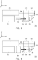
- FIG. 4 is a schematic view of a projection device from a perspective according to an embodiment of the disclosure.
- a projection device 100' in the embodiment may be adaptable for the projection device 100.
- the projection device 100' further includes a light integration rod 112 and a first optical lens set 114.
- the light integration rod 112 and the first optical lens set 114 are disposed on the transmission path of the illumination beam IL in sequence.
- the light integration rod 112 is configured to uniform the light and allow the beam that passes through to be uniformly and accurately outputted.
- the first optical lens set 114 has one or more optical lenses provided therein for calibrating beam.
- the illumination beam IL is transmitted to the light splitting and combining element 120 after passing through the light integration rod 112 and the first optical lens set 114.
- the light splitting and combining element 120 may be divided into two neighboring regions.
- the light splitting and combining element 120 is divided into upper and lower parts: the illumination beam IL from the illumination system 110 enters a first region BR, and an image light (including first color image light IB1 and second color image light IB2) from the light valve 130 and the light valve 140 enters a second region TR. That is, after the illumination beam IL enters the first region BR of the light splitting and combining element 120, the optical paths of the first color light R and the second color light G are spitted. Meanwhile, after the image light from the light valve 130 and the light valve 140 enters the second region TR of the light splitting and combining element 120, the first color image light IB1 and the second color image light IB2 are combined and transmitted to the image-forming lens 150.
- the alignment direction of the first region BR and the second region TR is as z direction shown in FIG. 1 or FIG. 4 and perpendicular to the transmission direction of the illumination beam IL between the illumination system 110 and the light splitting and combining element 120 as the positive x direction shown in FIG. 1 or FIG. 4 , and is also perpendicular to the transmission direction of the first color image light IB1 and the second color image light IB2 between the light splitting and combining element 120 and the image-forming lens 150 as the negative x direction shown in FIG. 1 or FIG. 4 .
- the transmission direction (negative x direction) of the first color image light IB1 and the second color image light IB2 between the light splitting and combining element 120 and the image-forming lens 150 is parallel with and opposite to the transmission direction (positive x direction) of the illumination beam IL between the illumination system 110 and the light splitting and combining element 120.
- the reflecting element M1 and the reflecting element M2 respectively reflect the first color light R and the second color light G from the first region BR such that the first color light R and the second color light G respectively pass through the first prism set 160 and the second prism set 170 and are transmitted to the light valve 130 and the light valve 140.
- the first prism set 160 and the second prism set 170 are exemplified as a prism set constructed by three splitting prisms; however, the disclosure provides no limitation to the number, the optical path and the light-splitting design of the first prism set 160 and the second prism set 170.
- a second optical lens set 162 is disposed on a beam transmission path between the reflecting element M1 and the first prism set 160.
- a third optical lens set 172 is further disposed on a beam transmission path between the reflecting element M2 and the second prism set 170, respectively configured to calibrate the reflected first color light R and the second color light G.
- the light valve 130 and the light valve 140 are respectively disposed on one side of the first prism set 160 and the second prism set 170, and the light-entering surface through which the first color light R enters the first prism set 160 is different from the light-exiting surface through which the first color image light IB1 leaves the first prism set 160.
- the light-entering surface through which the second color light G enters the second prism set 170 is different from the light-exiting surface through which the second color image light IB2 leaves the second prism set 170.
- the first color image color IB1 and the second color image light IB2 respectively leave the first prism set 160 and the second prism set 170 then to enter the second region TR of the light splitting and combining element 120.
- the first color image light IB1 passes through the second region TR of the light splitting and combining element 120 and is transmitted to the image-forming lens 150.
- the second color image light IB2 is reflected by the second region TR of the light splitting and combining element 120 to the image-forming lens 150.
- the illumination beam IL provided by the illumination system 110 of the projection device 100' includes a third color light B other than the first color light R and the second color light G.
- the blue beam is described as an example.
- the light splitting and combining element 120 allows the third color light B to pass through. Therefore, the transmission path of the third color light B from the light splitting and combining element 120 is the same as the transmission path of the first color light R, which should not be construed as a limitation to the disclosure.
- the light splitting and combining element 120 reflects the third color light B, and therefore the transmission path of the third color light B from the light splitting and combining element 120 is the same as the transmission path of the second color light G.
- one of the light valve 130 and the light valve 140 may convert the third color light B into a third color image light IB3.
- the third color image light IB3 may be transmitted to the image-forming lens 150 on one of the first color image light IB1's and the second color image light IB2's optical paths.
- the first color image light IB1, the second color image light IB2 and the third color image light IB3 are formed into the projection beam PB through the first prism set 160 as well as the second prism set 170 and the image-forming lens 150, thereby forming a projection image on the projection medium.
- the sufficient teaching, suggestions and implementation about how to form the projection image, regarding the detailed steps and method thereof, may be derived from common knowledge of the field; therefore, no repetition is incorporated herein.
- FIG. 5 is a schematic side view of a projection device according to an embodiment of the disclosure.
- a projection device 700 in the embodiment may be adaptable for the projection device 100 and the projection device 100' described above.
- the implementation method of the projection device 700 and the configuration relationship between the elements of the projection device 700 are similar to the projection device 100 shown in FIG. 1 and the projection device 100' shown in FIG. 4 .
- the main difference is that the projection device 700 not only includes the light integration rod 112 but also includes at least two filters, namely filter 180 and filter 182.
- the filter 180 is disposed on the transmission path of the first color light R that passes through the light splitting and combining element 120, and between the light splitting and combining element 120 and the light valve 130.
- the filter 182 is disposed on the transmission path of the second color light G reflected by the light splitting and combining element 120 and between the light splitting and combining element 120 and the light valve 140.
- FIG. 6 is a schematic side view of a projection device according to an embodiment of the disclosure.
- a projection device 800 in the embodiment may be adaptable for the projection device 100 shown in FIG. 1 , the projection device 100' shown in FIG. 4 or the projection device 700 shown in FIG. 5 .
- the implementation method of the projection device 800 and the configuration relationship between the elements of the projection device 800 are similar to the projection device 700.
- the main difference is that, as compared to the projection device 700, the projection device 800 also includes the filter 180 and the filter 182 but does not use the light integration rod 112; instead, the projection device 800 uses a lens array module 184.
- the lens array module 184 is disposed on the transmission path of the illumination beam IL, and the illumination beam IL is transmitted to the light splitting and combining element 120 after passing through the lens array module 184.
- the lens array module 184 is, for example, constructed by two sets of lens arrays facing away from each other and aligned with each other. Specifically, the convex surface of the lens array is regarded as the front surface, and the planar surface is regarded the rear surface.
- aligned arrangement refers to that the positions of lens unit of the two sets of lens arrays are aligned with each other.
- the beam passing through the lens array module 184 makes the light to be distributed uniformly.
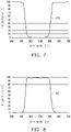
- FIG. 7 is a schematic view showing transmittance variation versus wavelength of a filter for allowing the first color light to pass therethrough according to an embodiment of the disclosure.
- FIG. 8 is a schematic view showing transmittance variation versus wavelength of a filter for allowing the second color light to pass therethrough according to an embodiment of the disclosure.
- the transmittance variation with respect to wavelength of the filter 180 of the projection device 700 and the projection device 800 may be as indicated by transmittance 410 shown in FIG. 7 .
- the first color light R is red beam. After the first color light R passes through the filter 180, other color light that is not red light may be filtered such that red color is more pure.
- the third color light B is blue beam.
- the filter 180 After the third color light B passes through the filter 180, other color light that is not blue color may be filtered such that blue color is more pure.
- the filter 180 has 100% transmittance with respect to the blue beam (third color light B) having wavelength less than 470 nm and the red beam (first color light R) having wavelength greater than 620 nm.
- the transmittance variation with respect to wavelength of the filter 182 may be as indicated by transmittance 510 shown in FIG. 8 .
- the second color light G is green beam. After the second color light G passes through the filter 182, other color light that is not green light may be filtered such that green color is more pure.
- the filter 182 has 100% transmittance with respect to the green beam (second color light G) having wavelength in a range between 500 nm and 565 nm.
- second color light G green beam
- the disclosure provides no limitation to the configuration position of the filter 180 and the filter 182.
- the embodiments shown in FIG. 5 and FIG. 6 only serve as examples.
- the filter may be disposed at any position on the transmission path of the single color beam (first color light R or second color light G).
- the disclosure provides no limitation to the range of the color light wavelength band that can be filtered by the filter 180 and the filter 182, which allow the color light with narrower wavelength band to pass through such that the color light is more pure.
- the exemplary embodiments of the disclosure provide a projection device, including the illumination system, the light splitting and combining element, at least two reflecting elements, at least two light valves and the image-forming lens.
- the illumination system provides the illumination beam.
- the light splitting and combining element is disposed on the transmission path of the illumination beam for splitting the illumination beam into the first color light and the second color light, and allows the first color light to pass through and reflects the second color light.
- the at least two reflecting elements respectively reflect the first color light and the second color light.
- the at least two light valves respectively convert the reflected first color light and the second color light into the first color image light and the second color image light, and the first color image light and the second color image light are transmitted to the light splitting and combining element.
- the first color image light passes through the light splitting and combining element to the image-forming lens, and the second color image light is reflected by the light splitting and combining element to the image-forming lens.
- the image-forming lens receives the first color image light and the second color image light to generate the projection beam.
- the illumination system and the image-forming lens of the projection device in the embodiment may be disposed on the same side, thereby reducing the volume of the projection device and improving compactness of the projection device.
Landscapes
- Physics & Mathematics (AREA)
- General Physics & Mathematics (AREA)
- Optics & Photonics (AREA)
- Projection Apparatus (AREA)
Claims (14)
- Dispositif de projection (100), comportant :un système d'éclairage (110), un élément de séparation et de combinaison de lumière (120), au moins deux modulateurs de lumière (130, 140) et une lentille de formation d'image (150),caractérisé en ce que le système d'éclairage (110) est configuré pour délivrer un faisceau d'éclairage (IL), le faisceau d'éclairage (IL) comportant une première lumière colorée (R) et une deuxième lumière colorée (G) ;l'élément de séparation et de combinaison de lumière (120) est disposé sur un trajet de transmission du faisceau d'éclairage (IL), et configuré pour permettre à la première lumière colorée (R) de passer à travers et de réfléchir la deuxième lumière colorée (G) ;les au moins deux modulateurs de lumière (130, 140) sont respectivement disposés sur des trajets de transmission de la première lumière colorée (R) et de de la deuxième lumière colorée (G) provenant de l'élément de séparation et de combinaison de lumière (120), et configurés pour convertir la première lumière colorée (R) et la deuxième lumière colorée (G) en une première lumière d'image en couleur (IB1) et une seconde lumière d'image en couleur (IB2) respectivement ; etla lentille de formation d'image (150) est disposée sur un trajet de transmission de la première lumière d'image en couleur (IB1) et de la seconde lumière d'image en couleur (IB2) provenant des au moins deux modulateurs de lumière (130, 140), et configurée pour recevoir la première lumière d'image en couleur (IB1) et la seconde lumière d'image en couleur (IB2) pour générer un faisceau de projection (PB),dans lequel la première lumière d'image en couleur (IB1) provenant de la première lumière colorée (R) traverse l'élément de séparation et de combinaison de lumière (120) jusqu'à la lentille de formation d'image (150), et la seconde lumière d'image en couleur (IB2) provenant de la deuxième lumière colorée (G) est réfléchie par l'élément de séparation et de combinaison de lumière (120) vers la lentille de formation d'image (150).
- Dispositif de projection (100) selon la revendication 1, comportant en outre au moins deux éléments réfléchissants (M1, M2) respectivement disposés sur les trajets de transmission de la première lumière colorée (R) et de la deuxième lumière colorée (G) provenant de l'élément de séparation et de combinaison de lumière (120), et configurés pour réfléchir respectivement la première lumière colorée (R) et la deuxième lumière colorée (G) vers les au moins deux modulateurs de lumière (130, 140).
- Dispositif de projection selon la revendication 1 ou 2, dans lequel une direction de transmission de la première lumière d'image en couleur (IB1) et de la seconde lumière d'image en couleur (IB2) entre l'élément de séparation et de combinaison de lumière (120) et la lentille de formation d'image (150) est parallèle et opposée à une direction de transmission du faisceau d'éclairage (IL) entre le système d'éclairage (110) et l'élément de séparation et de combinaison de lumière (120).
- Dispositif de projection selon l'une quelconque des revendications précédentes, dans lequel le système d'éclairage (110) et la lentille de formation d'image (150) sont disposés du même côté de l'élément de séparation et de combinaison de lumière (120).
- Dispositif de projection selon l'une quelconque des revendications précédentes, dans lequel l'élément de séparation et de combinaison de lumière (120) comporte une première zone (BR) et une seconde zone (TR) adjacentes l'une à l'autre, le faisceau d'éclairage (IL) provenant du système d'éclairage (110) entre dans la première zone (BR) de l'élément de séparation et de combinaison de lumière (120), la première lumière d'image en couleur (IB1) et la seconde lumière d'image en couleur (IB2) provenant des au moins deux modulateurs de lumière (130, 140) entrent dans la seconde zone (TR) de l'élément de séparation et de combinaison de lumière (120).
- Dispositif de projection selon la revendication 5, dans lequel une direction d'alignement de la première zone (BR) et de la seconde zone (TR) est perpendiculaire à une direction de transmission du faisceau d'éclairage (IL) entre le système d'éclairage (110) et l'élément de séparation et de combinaison de lumière (120), et la direction d'alignement de la première zone (BR) et de la seconde zone (TR) est perpendiculaire à une direction de transmission de la première lumière d'image en couleur (IB1) et de la deuxième lumière d'image en couleur (IB2) entre l'élément de séparation et de combinaison de lumière (120) et la lentille de formation d'image (150).
- Dispositif de projection selon la revendication 5, comportant en outre au moins deux éléments réfléchissants (M1, M2) respectivement disposés sur les trajets de transmission de la première lumière colorée (R) et de la deuxième lumière colorée (G) provenant de l'élément de séparation et de combinaison de lumière (120), et les au moins deux éléments réfléchissants (M1, M2) réfléchissent respectivement la première lumière colorée (R) et la deuxième lumière colorée (G) provenant de la première zone (BR) vers les au moins deux modulateurs de lumière (130, 140).
- Dispositif de projection selon la revendication 7, comportant en outre :un premier ensemble de prismes (160), disposé sur le trajet de transmission de la première lumière colorée (R) et ayant une première surface, une deuxième surface et une troisième surface,dans lequel la première lumière colorée (R) réfléchie par l'un des au moins deux éléments réfléchissants (M1, M2) entre dans le premier ensemble de prismes (160) par la première surface, et est transmise à l'un des au moins deux modulateurs de lumière (130, 140) après être sortie par la deuxième surface, dans lequel la première lumière d'image en couleur (IB1) entre dans le premier ensemble de prismes (160) par la deuxième surface, et est transmise à la seconde zone (TR) de l'élément de séparation et de combinaison de lumière (120) après être sortie par la troisième surface ; etun second ensemble de prismes (170), disposé sur le trajet de transmission de la deuxième lumière colorée (G) et ayant une quatrième surface, une cinquième surface et une sixième surface,dans lequel la deuxième lumière colorée (G) réfléchie par l'autre des au moins deux éléments réfléchissants (M1, M2) entre dans le second ensemble de prismes (170) par la quatrième surface, et est transmise à l'autre des au moins deux modulateurs de lumière (130, 140) après être sortie par la cinquième surface, dans lequel la deuxième lumière d'image en couleur (IB2) entre dans le second ensemble de prismes (170) par la cinquième surface, et est transmise à la seconde zone (TR) de l'élément de séparation et de combinaison de lumière (120) après être sortie par la sixième surface.
- Dispositif de projection selon l'une quelconque des revendications précédentes, dans lequel le faisceau d'éclairage (IL) comporte en outre une troisième lumière colorée (B).
- Dispositif de projection selon la revendication 9, dans lequel l'élément de séparation et de combinaison de lumière (120) permet à la troisième lumière colorée (B) de passer à travers, un trajet de transmission de la troisième lumière colorée (B) provenant de l'élément de séparation et de combinaison de lumière (120) étant le même que celui de la première lumière colorée (R).
- Dispositif de projection selon la revendication 9, dans lequel l'élément de séparation et de combinaison de lumière (120) réfléchit la troisième lumière colorée (B), et un trajet de transmission de la troisième lumière colorée (B) provenant de l'élément de séparation et de combinaison de lumière (120) étant le même que celui de la deuxième lumière colorée (G).
- Dispositif de projection selon l'une quelconque des revendications précédentes, dans lequel le système d'éclairage (100) comporte :
un barreau d'intégration de lumière (112), disposé sur le trajet de transmission du faisceau d'éclairage (IL), et le faisceau d'éclairage (IL) étant transmis à l'élément de séparation et de combinaison de lumière (120) après avoir traversé le barreau d'intégration de lumière (112). - Dispositif de projection selon l'une quelconque des revendications précédentes, comportant en outre :
deux filtres (180, 182) respectivement disposés sur des trajets de transmission de la première ligne colorée (R) et de la deuxième lumière colorée (G), et respectivement disposés entre l'élément de séparation et de combinaison de lumière (120) et les au moins deux modulateurs de lumière (130, 140). - Dispositif de projection selon l'une quelconque des revendications précédentes, dans lequel le système d'éclairage (110) comporte :
un module de matrice de lentilles (184), disposé sur le trajet de transmission du faisceau d'éclairage (IL), et le faisceau d'éclairage (IL) étant transmis à l'élément de séparation et de combinaison de lumière (120) après avoir traversé le module de matrice de lentilles (184).
Applications Claiming Priority (1)
| Application Number | Priority Date | Filing Date | Title |
|---|---|---|---|
| CN201810151181.6A CN110161787B (zh) | 2018-02-14 | 2018-02-14 | 投影装置 |
Publications (2)
| Publication Number | Publication Date |
|---|---|
| EP3528044A1 EP3528044A1 (fr) | 2019-08-21 |
| EP3528044B1 true EP3528044B1 (fr) | 2022-04-13 |
Family
ID=65433471
Family Applications (1)
| Application Number | Title | Priority Date | Filing Date |
|---|---|---|---|
| EP19156686.8A Active EP3528044B1 (fr) | 2018-02-14 | 2019-02-12 | Dispositif de projection |
Country Status (3)
| Country | Link |
|---|---|
| US (1) | US10642146B2 (fr) |
| EP (1) | EP3528044B1 (fr) |
| CN (1) | CN110161787B (fr) |
Families Citing this family (1)
| Publication number | Priority date | Publication date | Assignee | Title |
|---|---|---|---|---|
| CN115113391B (zh) * | 2021-03-18 | 2024-08-27 | 中强光电股份有限公司 | 光机模块与投影装置 |
Family Cites Families (18)
| Publication number | Priority date | Publication date | Assignee | Title |
|---|---|---|---|---|
| US6561652B1 (en) * | 1998-12-22 | 2003-05-13 | Vanntelligent (Bvi) Limited | Optical assembly for reflective light valves |
| US7004587B2 (en) * | 2004-01-28 | 2006-02-28 | Himax Technologies, Inc. | Projection display apparatus with two reflective light panels |
| US20060256289A1 (en) | 2004-04-30 | 2006-11-16 | Yoshio Fukuzaki | Projection display apparatus |
| TWI403821B (zh) * | 2009-10-28 | 2013-08-01 | Young Optics Inc | 照明系統及投影裝置 |
| US8888290B2 (en) * | 2011-04-08 | 2014-11-18 | Hong Kong Applied Science and Technology Research Institute Company Limited | Polarization beam splitters for image projection apparatus |
| JP2013114229A (ja) * | 2011-11-30 | 2013-06-10 | Sanyo Electric Co Ltd | 光源装置及び投写型映像表示装置 |
| JP6080381B2 (ja) * | 2012-04-26 | 2017-02-15 | キヤノン株式会社 | 光学系およびそれを用いた投射型表示装置 |
| CN103631075B (zh) * | 2012-08-24 | 2016-08-03 | 扬明光学股份有限公司 | 照明系统、投影装置及照明方法 |
| US9664989B2 (en) | 2013-05-23 | 2017-05-30 | Texas Instruments Incorporated | Multi-spatial light modulator image display projector architectures using solid state light sources |
| US9885946B2 (en) * | 2014-03-05 | 2018-02-06 | Nec Display Solutions, Ltd. | Projection type display apparatus and image display method |
| CN109188837B (zh) | 2014-04-23 | 2020-12-08 | 深圳光峰科技股份有限公司 | 光源系统、投影系统及方法 |
| US10732495B2 (en) * | 2014-05-02 | 2020-08-04 | Coretronic Corporation | Illumination system, projection apparatus and method for driving illumination system |
| WO2016165569A1 (fr) * | 2015-04-09 | 2016-10-20 | 深圳市光峰光电技术有限公司 | Dispositif électroluminescent et système de projection |
| CN106371272B (zh) | 2015-07-20 | 2019-04-23 | 深圳光峰科技股份有限公司 | 合光的控制系统及投影机 |
| JP6814978B2 (ja) | 2016-02-10 | 2021-01-20 | パナソニックIpマネジメント株式会社 | 投写型映像表示装置 |
| CN109765745B (zh) * | 2017-11-09 | 2021-08-17 | 深圳光峰科技股份有限公司 | 光源装置及投影系统 |
| CN207851427U (zh) | 2018-02-02 | 2018-09-11 | 中强光电股份有限公司 | 投影装置及光机模块 |
| CN207937747U (zh) * | 2018-02-14 | 2018-10-02 | 中强光电股份有限公司 | 投影装置 |
-
2018
- 2018-02-14 CN CN201810151181.6A patent/CN110161787B/zh active Active
-
2019
- 2019-02-11 US US16/271,888 patent/US10642146B2/en active Active
- 2019-02-12 EP EP19156686.8A patent/EP3528044B1/fr active Active
Also Published As
| Publication number | Publication date |
|---|---|
| EP3528044A1 (fr) | 2019-08-21 |
| CN110161787A (zh) | 2019-08-23 |
| CN110161787B (zh) | 2021-08-27 |
| US10642146B2 (en) | 2020-05-05 |
| US20190250499A1 (en) | 2019-08-15 |
Similar Documents
| Publication | Publication Date | Title |
|---|---|---|
| US9977317B2 (en) | Illumination system and projection device | |
| US9645480B2 (en) | Light source module and projection apparatus having the same | |
| EP3594747A1 (fr) | Système d'éclairage et dispositif de projection | |
| US11442351B2 (en) | Illumination system and projection apparatus for enhancing uniformity of illumination light beams | |
| US20190086779A1 (en) | Illumination system and projection apparatus | |
| CN108572504A (zh) | 投影系统 | |
| US12332559B2 (en) | Illumination system and projection apparatus | |
| TW201839494A (zh) | 照明系統 | |
| US10838291B2 (en) | Illumination system and projection device | |
| US10969673B2 (en) | Polarization rotation device and projection device | |
| CN108628073A (zh) | 光学系统 | |
| US11874590B2 (en) | Illumination system and projection device | |
| EP3528044B1 (fr) | Dispositif de projection | |
| EP3923069A1 (fr) | Dispositif de projection | |
| CN210573154U (zh) | 照明系统以及投影装置 | |
| CN207937747U (zh) | 投影装置 | |
| US11803114B2 (en) | Illumination system and projection apparatus | |
| TWI730146B (zh) | 光學系統 | |
| US20230140825A1 (en) | Beam splitter/combiner and projection apparatus | |
| US11543741B2 (en) | Illumination system and projection device | |
| US20210041776A1 (en) | Lighting system and projection device | |
| CN109459906B (zh) | 光学系统 | |
| US20250251655A1 (en) | Illumination system and projection device | |
| US20250102894A1 (en) | Illumination system and projection device | |
| US20240027886A1 (en) | Illumination system and projection device |
Legal Events
| Date | Code | Title | Description |
|---|---|---|---|
| PUAI | Public reference made under article 153(3) epc to a published international application that has entered the european phase |
Free format text: ORIGINAL CODE: 0009012 |
|
| STAA | Information on the status of an ep patent application or granted ep patent |
Free format text: STATUS: THE APPLICATION HAS BEEN PUBLISHED |
|
| AK | Designated contracting states |
Kind code of ref document: A1 Designated state(s): AL AT BE BG CH CY CZ DE DK EE ES FI FR GB GR HR HU IE IS IT LI LT LU LV MC MK MT NL NO PL PT RO RS SE SI SK SM TR |
|
| AX | Request for extension of the european patent |
Extension state: BA ME |
|
| STAA | Information on the status of an ep patent application or granted ep patent |
Free format text: STATUS: REQUEST FOR EXAMINATION WAS MADE |
|
| 17P | Request for examination filed |
Effective date: 20200122 |
|
| RBV | Designated contracting states (corrected) |
Designated state(s): AL AT BE BG CH CY CZ DE DK EE ES FI FR GB GR HR HU IE IS IT LI LT LU LV MC MK MT NL NO PL PT RO RS SE SI SK SM TR |
|
| GRAP | Despatch of communication of intention to grant a patent |
Free format text: ORIGINAL CODE: EPIDOSNIGR1 |
|
| STAA | Information on the status of an ep patent application or granted ep patent |
Free format text: STATUS: GRANT OF PATENT IS INTENDED |
|
| RIC1 | Information provided on ipc code assigned before grant |
Ipc: G03B 33/12 20060101ALN20211026BHEP Ipc: G03B 21/20 20060101AFI20211026BHEP |
|
| RIC1 | Information provided on ipc code assigned before grant |
Ipc: G03B 33/12 20060101ALN20211105BHEP Ipc: G03B 21/20 20060101AFI20211105BHEP |
|
| INTG | Intention to grant announced |
Effective date: 20211126 |
|
| GRAS | Grant fee paid |
Free format text: ORIGINAL CODE: EPIDOSNIGR3 |
|
| GRAA | (expected) grant |
Free format text: ORIGINAL CODE: 0009210 |
|
| STAA | Information on the status of an ep patent application or granted ep patent |
Free format text: STATUS: THE PATENT HAS BEEN GRANTED |
|
| AK | Designated contracting states |
Kind code of ref document: B1 Designated state(s): AL AT BE BG CH CY CZ DE DK EE ES FI FR GB GR HR HU IE IS IT LI LT LU LV MC MK MT NL NO PL PT RO RS SE SI SK SM TR |
|
| REG | Reference to a national code |
Ref country code: GB Ref legal event code: FG4D |
|
| REG | Reference to a national code |
Ref country code: CH Ref legal event code: EP |
|
| REG | Reference to a national code |
Ref country code: DE Ref legal event code: R096 Ref document number: 602019013568 Country of ref document: DE |
|
| REG | Reference to a national code |
Ref country code: IE Ref legal event code: FG4D |
|
| REG | Reference to a national code |
Ref country code: AT Ref legal event code: REF Ref document number: 1483851 Country of ref document: AT Kind code of ref document: T Effective date: 20220515 |
|
| REG | Reference to a national code |
Ref country code: LT Ref legal event code: MG9D |
|
| REG | Reference to a national code |
Ref country code: NL Ref legal event code: MP Effective date: 20220413 |
|
| REG | Reference to a national code |
Ref country code: AT Ref legal event code: MK05 Ref document number: 1483851 Country of ref document: AT Kind code of ref document: T Effective date: 20220413 |
|
| PG25 | Lapsed in a contracting state [announced via postgrant information from national office to epo] |
Ref country code: NL Free format text: LAPSE BECAUSE OF FAILURE TO SUBMIT A TRANSLATION OF THE DESCRIPTION OR TO PAY THE FEE WITHIN THE PRESCRIBED TIME-LIMIT Effective date: 20220413 |
|
| PG25 | Lapsed in a contracting state [announced via postgrant information from national office to epo] |
Ref country code: SE Free format text: LAPSE BECAUSE OF FAILURE TO SUBMIT A TRANSLATION OF THE DESCRIPTION OR TO PAY THE FEE WITHIN THE PRESCRIBED TIME-LIMIT Effective date: 20220413 Ref country code: PT Free format text: LAPSE BECAUSE OF FAILURE TO SUBMIT A TRANSLATION OF THE DESCRIPTION OR TO PAY THE FEE WITHIN THE PRESCRIBED TIME-LIMIT Effective date: 20220816 Ref country code: NO Free format text: LAPSE BECAUSE OF FAILURE TO SUBMIT A TRANSLATION OF THE DESCRIPTION OR TO PAY THE FEE WITHIN THE PRESCRIBED TIME-LIMIT Effective date: 20220713 Ref country code: LT Free format text: LAPSE BECAUSE OF FAILURE TO SUBMIT A TRANSLATION OF THE DESCRIPTION OR TO PAY THE FEE WITHIN THE PRESCRIBED TIME-LIMIT Effective date: 20220413 Ref country code: HR Free format text: LAPSE BECAUSE OF FAILURE TO SUBMIT A TRANSLATION OF THE DESCRIPTION OR TO PAY THE FEE WITHIN THE PRESCRIBED TIME-LIMIT Effective date: 20220413 Ref country code: GR Free format text: LAPSE BECAUSE OF FAILURE TO SUBMIT A TRANSLATION OF THE DESCRIPTION OR TO PAY THE FEE WITHIN THE PRESCRIBED TIME-LIMIT Effective date: 20220714 Ref country code: FI Free format text: LAPSE BECAUSE OF FAILURE TO SUBMIT A TRANSLATION OF THE DESCRIPTION OR TO PAY THE FEE WITHIN THE PRESCRIBED TIME-LIMIT Effective date: 20220413 Ref country code: ES Free format text: LAPSE BECAUSE OF FAILURE TO SUBMIT A TRANSLATION OF THE DESCRIPTION OR TO PAY THE FEE WITHIN THE PRESCRIBED TIME-LIMIT Effective date: 20220413 Ref country code: BG Free format text: LAPSE BECAUSE OF FAILURE TO SUBMIT A TRANSLATION OF THE DESCRIPTION OR TO PAY THE FEE WITHIN THE PRESCRIBED TIME-LIMIT Effective date: 20220713 Ref country code: AT Free format text: LAPSE BECAUSE OF FAILURE TO SUBMIT A TRANSLATION OF THE DESCRIPTION OR TO PAY THE FEE WITHIN THE PRESCRIBED TIME-LIMIT Effective date: 20220413 |
|
| PG25 | Lapsed in a contracting state [announced via postgrant information from national office to epo] |
Ref country code: RS Free format text: LAPSE BECAUSE OF FAILURE TO SUBMIT A TRANSLATION OF THE DESCRIPTION OR TO PAY THE FEE WITHIN THE PRESCRIBED TIME-LIMIT Effective date: 20220413 Ref country code: PL Free format text: LAPSE BECAUSE OF FAILURE TO SUBMIT A TRANSLATION OF THE DESCRIPTION OR TO PAY THE FEE WITHIN THE PRESCRIBED TIME-LIMIT Effective date: 20220413 Ref country code: LV Free format text: LAPSE BECAUSE OF FAILURE TO SUBMIT A TRANSLATION OF THE DESCRIPTION OR TO PAY THE FEE WITHIN THE PRESCRIBED TIME-LIMIT Effective date: 20220413 Ref country code: IS Free format text: LAPSE BECAUSE OF FAILURE TO SUBMIT A TRANSLATION OF THE DESCRIPTION OR TO PAY THE FEE WITHIN THE PRESCRIBED TIME-LIMIT Effective date: 20220813 |
|
| REG | Reference to a national code |
Ref country code: DE Ref legal event code: R097 Ref document number: 602019013568 Country of ref document: DE |
|
| PG25 | Lapsed in a contracting state [announced via postgrant information from national office to epo] |
Ref country code: SM Free format text: LAPSE BECAUSE OF FAILURE TO SUBMIT A TRANSLATION OF THE DESCRIPTION OR TO PAY THE FEE WITHIN THE PRESCRIBED TIME-LIMIT Effective date: 20220413 Ref country code: SK Free format text: LAPSE BECAUSE OF FAILURE TO SUBMIT A TRANSLATION OF THE DESCRIPTION OR TO PAY THE FEE WITHIN THE PRESCRIBED TIME-LIMIT Effective date: 20220413 Ref country code: RO Free format text: LAPSE BECAUSE OF FAILURE TO SUBMIT A TRANSLATION OF THE DESCRIPTION OR TO PAY THE FEE WITHIN THE PRESCRIBED TIME-LIMIT Effective date: 20220413 Ref country code: EE Free format text: LAPSE BECAUSE OF FAILURE TO SUBMIT A TRANSLATION OF THE DESCRIPTION OR TO PAY THE FEE WITHIN THE PRESCRIBED TIME-LIMIT Effective date: 20220413 Ref country code: DK Free format text: LAPSE BECAUSE OF FAILURE TO SUBMIT A TRANSLATION OF THE DESCRIPTION OR TO PAY THE FEE WITHIN THE PRESCRIBED TIME-LIMIT Effective date: 20220413 Ref country code: CZ Free format text: LAPSE BECAUSE OF FAILURE TO SUBMIT A TRANSLATION OF THE DESCRIPTION OR TO PAY THE FEE WITHIN THE PRESCRIBED TIME-LIMIT Effective date: 20220413 |
|
| PLBE | No opposition filed within time limit |
Free format text: ORIGINAL CODE: 0009261 |
|
| STAA | Information on the status of an ep patent application or granted ep patent |
Free format text: STATUS: NO OPPOSITION FILED WITHIN TIME LIMIT |
|
| 26N | No opposition filed |
Effective date: 20230116 |
|
| PG25 | Lapsed in a contracting state [announced via postgrant information from national office to epo] |
Ref country code: AL Free format text: LAPSE BECAUSE OF FAILURE TO SUBMIT A TRANSLATION OF THE DESCRIPTION OR TO PAY THE FEE WITHIN THE PRESCRIBED TIME-LIMIT Effective date: 20220413 |
|
| PG25 | Lapsed in a contracting state [announced via postgrant information from national office to epo] |
Ref country code: SI Free format text: LAPSE BECAUSE OF FAILURE TO SUBMIT A TRANSLATION OF THE DESCRIPTION OR TO PAY THE FEE WITHIN THE PRESCRIBED TIME-LIMIT Effective date: 20220413 |
|
| PG25 | Lapsed in a contracting state [announced via postgrant information from national office to epo] |
Ref country code: MC Free format text: LAPSE BECAUSE OF FAILURE TO SUBMIT A TRANSLATION OF THE DESCRIPTION OR TO PAY THE FEE WITHIN THE PRESCRIBED TIME-LIMIT Effective date: 20220413 |
|
| REG | Reference to a national code |
Ref country code: CH Ref legal event code: PL |
|
| REG | Reference to a national code |
Ref country code: BE Ref legal event code: MM Effective date: 20230228 |
|
| PG25 | Lapsed in a contracting state [announced via postgrant information from national office to epo] |
Ref country code: LU Free format text: LAPSE BECAUSE OF NON-PAYMENT OF DUE FEES Effective date: 20230212 Ref country code: LI Free format text: LAPSE BECAUSE OF NON-PAYMENT OF DUE FEES Effective date: 20230228 Ref country code: CH Free format text: LAPSE BECAUSE OF NON-PAYMENT OF DUE FEES Effective date: 20230228 |
|
| REG | Reference to a national code |
Ref country code: IE Ref legal event code: MM4A |
|
| PG25 | Lapsed in a contracting state [announced via postgrant information from national office to epo] |
Ref country code: IT Free format text: LAPSE BECAUSE OF FAILURE TO SUBMIT A TRANSLATION OF THE DESCRIPTION OR TO PAY THE FEE WITHIN THE PRESCRIBED TIME-LIMIT Effective date: 20220413 Ref country code: IE Free format text: LAPSE BECAUSE OF NON-PAYMENT OF DUE FEES Effective date: 20230212 |
|
| PG25 | Lapsed in a contracting state [announced via postgrant information from national office to epo] |
Ref country code: BE Free format text: LAPSE BECAUSE OF NON-PAYMENT OF DUE FEES Effective date: 20230228 |
|
| PG25 | Lapsed in a contracting state [announced via postgrant information from national office to epo] |
Ref country code: BG Free format text: LAPSE BECAUSE OF FAILURE TO SUBMIT A TRANSLATION OF THE DESCRIPTION OR TO PAY THE FEE WITHIN THE PRESCRIBED TIME-LIMIT Effective date: 20220413 |
|
| PG25 | Lapsed in a contracting state [announced via postgrant information from national office to epo] |
Ref country code: BG Free format text: LAPSE BECAUSE OF FAILURE TO SUBMIT A TRANSLATION OF THE DESCRIPTION OR TO PAY THE FEE WITHIN THE PRESCRIBED TIME-LIMIT Effective date: 20220413 |
|
| PG25 | Lapsed in a contracting state [announced via postgrant information from national office to epo] |
Ref country code: CY Free format text: LAPSE BECAUSE OF FAILURE TO SUBMIT A TRANSLATION OF THE DESCRIPTION OR TO PAY THE FEE WITHIN THE PRESCRIBED TIME-LIMIT; INVALID AB INITIO Effective date: 20190212 |
|
| PG25 | Lapsed in a contracting state [announced via postgrant information from national office to epo] |
Ref country code: HU Free format text: LAPSE BECAUSE OF FAILURE TO SUBMIT A TRANSLATION OF THE DESCRIPTION OR TO PAY THE FEE WITHIN THE PRESCRIBED TIME-LIMIT; INVALID AB INITIO Effective date: 20190212 |
|
| PG25 | Lapsed in a contracting state [announced via postgrant information from national office to epo] |
Ref country code: TR Free format text: LAPSE BECAUSE OF FAILURE TO SUBMIT A TRANSLATION OF THE DESCRIPTION OR TO PAY THE FEE WITHIN THE PRESCRIBED TIME-LIMIT Effective date: 20220413 |
|
| PGFP | Annual fee paid to national office [announced via postgrant information from national office to epo] |
Ref country code: GB Payment date: 20260219 Year of fee payment: 8 |
|
| PGFP | Annual fee paid to national office [announced via postgrant information from national office to epo] |
Ref country code: DE Payment date: 20260226 Year of fee payment: 8 |
|
| PGFP | Annual fee paid to national office [announced via postgrant information from national office to epo] |
Ref country code: FR Payment date: 20260223 Year of fee payment: 8 |