EP3528065A1 - Procédé de surveillance, de commande et de mise hors tension contrôlée des unités de commande et/ou des unités informatiques - Google Patents
Procédé de surveillance, de commande et de mise hors tension contrôlée des unités de commande et/ou des unités informatiques Download PDFInfo
- Publication number
- EP3528065A1 EP3528065A1 EP18156871.8A EP18156871A EP3528065A1 EP 3528065 A1 EP3528065 A1 EP 3528065A1 EP 18156871 A EP18156871 A EP 18156871A EP 3528065 A1 EP3528065 A1 EP 3528065A1
- Authority
- EP
- European Patent Office
- Prior art keywords
- power supply
- control
- supply components
- control system
- applications
- Prior art date
- Legal status (The legal status is an assumption and is not a legal conclusion. Google has not performed a legal analysis and makes no representation as to the accuracy of the status listed.)
- Granted
Links
Images

Classifications
-
- G—PHYSICS
- G06—COMPUTING OR CALCULATING; COUNTING
- G06F—ELECTRIC DIGITAL DATA PROCESSING
- G06F1/00—Details not covered by groups G06F3/00 - G06F13/00 and G06F21/00
- G06F1/26—Power supply means, e.g. regulation thereof
- G06F1/30—Means for acting in the event of power-supply failure or interruption, e.g. power-supply fluctuations
-
- G—PHYSICS
- G05—CONTROLLING; REGULATING
- G05B—CONTROL OR REGULATING SYSTEMS IN GENERAL; FUNCTIONAL ELEMENTS OF SUCH SYSTEMS; MONITORING OR TESTING ARRANGEMENTS FOR SUCH SYSTEMS OR ELEMENTS
- G05B19/00—Program-control systems
- G05B19/02—Program-control systems electric
- G05B19/04—Program control other than numerical control, i.e. in sequence controllers or logic controllers
- G05B19/042—Program control other than numerical control, i.e. in sequence controllers or logic controllers using digital processors
-
- G—PHYSICS
- G06—COMPUTING OR CALCULATING; COUNTING
- G06F—ELECTRIC DIGITAL DATA PROCESSING
- G06F1/00—Details not covered by groups G06F3/00 - G06F13/00 and G06F21/00
- G06F1/26—Power supply means, e.g. regulation thereof
- G06F1/32—Means for saving power
- G06F1/3203—Power management, i.e. event-based initiation of a power-saving mode
-
- G—PHYSICS
- G06—COMPUTING OR CALCULATING; COUNTING
- G06F—ELECTRIC DIGITAL DATA PROCESSING
- G06F1/00—Details not covered by groups G06F3/00 - G06F13/00 and G06F21/00
- G06F1/26—Power supply means, e.g. regulation thereof
- G06F1/32—Means for saving power
- G06F1/3203—Power management, i.e. event-based initiation of a power-saving mode
- G06F1/3206—Monitoring of events, devices or parameters that trigger a change in power modality
-
- G—PHYSICS
- G06—COMPUTING OR CALCULATING; COUNTING
- G06F—ELECTRIC DIGITAL DATA PROCESSING
- G06F1/00—Details not covered by groups G06F3/00 - G06F13/00 and G06F21/00
- G06F1/26—Power supply means, e.g. regulation thereof
- G06F1/32—Means for saving power
- G06F1/3203—Power management, i.e. event-based initiation of a power-saving mode
- G06F1/3234—Power saving characterised by the action undertaken
- G06F1/3287—Power saving characterised by the action undertaken by switching off individual functional units in the computer system
-
- G—PHYSICS
- G05—CONTROLLING; REGULATING
- G05B—CONTROL OR REGULATING SYSTEMS IN GENERAL; FUNCTIONAL ELEMENTS OF SUCH SYSTEMS; MONITORING OR TESTING ARRANGEMENTS FOR SUCH SYSTEMS OR ELEMENTS
- G05B2219/00—Program-control systems
- G05B2219/20—Pc systems
- G05B2219/24—Pc safety
- G05B2219/24146—Configure actuators to be switched off in case of emergency stop
Definitions
- the subject invention relates to a method for monitoring, controlling and controlled shutdown of control and / or computer units of at least one system.
- the at least one system has power supply components, in particular electrical power supplies, electrical fuses, uninterruptible power supplies, etc., of which a power supply of the control and / or computer units is ensured.
- industrial plants usually comprise control and / or computer units, such as e.g. so-called industrial PCs and / or intelligent electronic, mostly microprocessor-based devices (eg control devices, protective devices, pressure and temperature transmitters, flow meters, actuators, programmable logic controllers, etc.), controlled by which plant-internal or plant-specific processes, monitors and / or controlled become.
- control devices e.g. control devices, protective devices, pressure and temperature transmitters, flow meters, actuators, programmable logic controllers, etc.
- microprocessor-based devices eg control devices, protective devices, pressure and temperature transmitters, flow meters, actuators, programmable logic controllers, etc.
- power supply components are used in a system.
- Under power supply components are all components in a current path such as electrical power supplies and / or switching power supplies, electrical fuses, uninterruptible power supplies, power storage (eg accumulator, capacitor, superconducting magnetic Energy storage, etc.), measuring units, etc. understood, which monitor the supply of the respective control and / or computer unit with energy over this current path, control and ensure and thus ensure trouble-free operations in the system.
- power storage eg accumulator, capacitor, superconducting magnetic Energy storage, etc.
- UPS uninterruptible power supplies
- UPS uninterruptible power supplies
- UPS uninterruptible power supplies
- UPS uninterruptible power supplies
- UPS uninterruptible power supplies
- UPS uninterruptible power supplies
- UPS uninterruptible power supplies
- UPS uninterruptible power supplies
- UPS uninterruptible power supplies
- UPS uninterruptible power supplies
- UPS uninterruptible power supplies
- UPS uninterruptible power supplies
- UPS uninterruptible power supply
- UPS uninterruptible power supply
- the uninterruptible power supply is used to provide an alternative power supply for each connected control and / or computer unit with the help of one or more energy storage modules (eg accumulator modules, batteries) in case of failure or failure of the power supply.
- the power supply of a control and / or computer unit by the energy storage of a UPS has the disadvantage that the one or more energy storage can provide only for a certain duration for the power supply.
- These actions range, for example, from a reduction of energy consumption (eg reduction of the display brightness, termination of applications) via sending warnings that the battery reserve has fallen below predetermined thresholds, to the controlled turning off of the mobile terminal falls below a minimum battery reserve, usually running applications are terminated properly and data is backed up before the device is turned off.
- a reduction of energy consumption eg reduction of the display brightness, termination of applications
- an uninterruptible power supply system in which a server unit is powered by two uninterruptible power supplies of a server unit.
- the two power supplies are connected to the server unit via a communication network and communicate with the server unit when a fault is detected in the power grid or when one or both power supplies is switched to battery operation.
- the server unit for a waiting time is stored, after the expiry of a shutdown of the server unit is started.
- the software components of the other consumers are defined as slaves in the sense of a master-slave communication and registered the master in the power supply as a communication partner for the implementation of the regulated shutdown. In the case of the error of the supply voltage or when switching to the buffer voltage, this is communicated to the master of the power supply and thus started the regulated shutdown or a shutdown sequence.
- the slaves must be switched off before the master - ie a waiting time (ie the time until the start of the controlled shutdown) must be shorter, for example, for the slaves than for the master.
- a waiting time ie the time until the start of the controlled shutdown
- such a method has a relatively complex communication or time-consuming administration, since it must be set up separately for each uninterruptible power supply of a system and the respective associated consumers.
- the invention is therefore based on the object to provide a comparison with the prior art improved method for monitoring, controlling and controlled shutdown of control and / or computer units at least one system.
- the object is achieved by a method for monitoring, controlling and controlled shutdown of control and / or computer units of at least one system.
- the control and / or computer units by means of power supply components such as electrical power supplies and / or switching power supplies, electrical fuses, uninterruptible power supplies, power storage (eg accumulator, capacitor, superconducting magnetic energy storage, etc.), measuring units, etc. are supplied with energy.
- power supply components such as electrical power supplies and / or switching power supplies, electrical fuses, uninterruptible power supplies, power storage (eg accumulator, capacitor, superconducting magnetic energy storage, etc.), measuring units, etc.
- power storage eg accumulator, capacitor, superconducting magnetic energy storage, etc.
- measuring units etc.
- a control application is installed on the control and / or computer units of the at least one system.
- a communication network is used to establish a connection to a control system for power supply components.
- control applications installed on the control and / or computer units of the at least one system are identified and the power supply components of the at least one system associated with the respective identified control applications.
- the established mappings between the power supply components and identified control applications are then stored and the power supply components for event alarms (eg, power failure, power supply component failure such as overheating or failure, switching to backup mode buffering, low battery power with uninterruptible power supply, etc.) monitored.
- event alarms eg, power failure, power supply component failure such as overheating or failure, switching to backup mode buffering, low battery power with uninterruptible power supply, etc.
- event alarms e.g. power failure, power supply component failure such as overheating or failure, switching to backup mode buffering, low battery power with uninterruptible power supply, etc.
- the main aspect of the proposed solution according to the invention is that by means of a control system for power supply components all control applications are detected and detected which are installed and available on the respective control and / or computer units of the at least one system. Furthermore, an assignment to the power supply components takes place centrally via the control system for power supply components, enabling time-saving and flexible configuration and administration. Furthermore, the method according to the invention makes it unnecessary to distinguish between two types of control applications or shutdown control and / or computer units (eg master / slave). By means of the method according to the invention, each power supply component is assigned at least the control applications of the control and / or computer units directly supplied with energy by this power supply component.
- the power supply control system provides both data on the power supply components available or used in the system and available control applications.
- the mappings between power supply components and control applications can thus be easily and flexibly, e.g. be carried out on the basis of an installation plan.
- waiting times and / or necessary shutdown times of individual control and / or computer units can be taken into account very easily. If necessary, it can be checked during allocation whether, for example, control and / or computer units have to be shut down in a predetermined sequence or sequence.
- the use of the control system for power supply components and a central allocation allows a reduction of a communication load of the individual power supply components as well as for the control and / or computer units.
- the control applications identified by the control system for power supply components are output on at least one input / output unit for the assignment of the power supply components to the control applications.
- the at least one input / output unit can be connected to the control system for power supply components.
- a connection of the input / output unit to the control system can be done for example by means of an application, in particular web application.
- a standardized Internet or web browser can be used as user interface for an output or display of the identified power supply components and control applications, as well as for carrying out the assignment.
- a stationary PC e.g., without additional effort or without restrictions, a stationary PC, stationary PC systems and mobile devices (eg tablet PC, handheld, etc.) can be used for the input / output unit or as a display.
- a stationary PC e.g tablet PC, handheld, etc.
- mobile devices eg tablet PC, handheld, etc.
- cloud computing via which, for example, the input / output unit or the output of the power supply components and control applications as well as assignment functionality are made available by means of applications.
- configuration parameters and / or predefinable actions for the respective control application are entered or set after the allocation between power supply components and identified control applications. This can e.g. take place via the at least one input / output unit which is connected to the control system for power supply components.
- the configuration of the respective control application may be e.g. be adapted to the respectively assigned power supply component. For example, configuration parameters such as e.g. Buffering or waiting times in case of an event alarm such as "Power supply switches to buffer or battery operation". During these buffering or waiting times, the control application may e.g. no actions or preparatory actions for shutting down the control and / or computer unit are initiated.
- actions to be initiated for the respective control application can be set. For example, when switching off / failure of a power supply component because of eg overheating, faults in the power supply network, etc., an immediate shutdown of the supplied control and / or computer units can be set as an action.
- an uninterruptible power supply as an assigned power supply component, for example, when setting the predefinable actions for the respective control applications, the buffer operation (ie a switch to a battery operation) are taken into account.
- the respective control and / or computer unit can be instructed by the associated control application, for example, at an event alarm "switch to buffer mode" of the power supply energy saving measures to initiate (eg, darken or turn off display units, etc.), terminate applications, etc. and to start a controlled shutdown only after an event alarm "low battery status” and / or after expiry of a predetermined waiting time.
- an event alarm "switch to buffer mode" of the power supply energy saving measures to initiate (eg, darken or turn off display units, etc.), terminate applications, etc. and to start a controlled shutdown only after an event alarm "low battery status" and / or after expiry of a predetermined waiting time.
- An expedient development of the method according to the invention provides that an authentication is provided for the assignment between power supply components and identified control applications and / or for an input of configuration parameters and / or predefinable actions of the control applications.
- a range of displayed data eg, identified power supply components and / or control applications
- / or permissible allocation and / or configuration options may ideally be defined by different user roles.
- access via the at least one input / output unit to the data and assignment and configuration options or to the control system for power supply components is restricted in a simple and efficient manner and protected against manipulation and unauthorized access.
- a user name with associated password can be used.
- different views can be offered on power supply components and control applications - eg restrictions to certain sections of the plant, to one or more plants, output of data for diagnostic purposes only, etc.
- control system for power supply components a control system comprising a centralized database server unit, local server units fixedly assigned to the power supply components, and client units to each local server unit is used.
- a control system for power supply components is from the previously unpublished European patent application EP 18156846.0 known.
- EP 18156846.0 European patent application
- Such a control system has the advantage that a load on the power supply components by data communication and data processing is minimized because, for example, data on the power supply components can be provided by the control system and need not be queried directly from the respective power supply components.
- control system and in particular the central server unit with the associated database thus represent a kind of "data turnstile" for assignment, administration and configuration of the control applications available in at least one system, through which the communication and data load on the individual power supply component, but also the respective control applications is significantly reduced.
- the communication and data processing architecture of the control system enables a server / client franchisable relationship, ideally an n-to-m relationship.
- the control system is accessed - eg via at least one input / output unit by means of client applications.
- client applications are predetermined, for example, by the configuration, capacity, etc. of the control system, in particular the central server unit, and are therefore independent of the number of power supply components and control applications identified by the control system.
- offers such a Control system as in the previously unpublished European patent application EP 18156846.0 described, the advantage that it is functional without functional limitations on various hardware architecture variants (eg stationary PC system, distributed computer system, cloud computing). In this way, the control system can very simply establish a connection to at least one installation or its power supply components and control applications via a communications network (eg Ethernet).
- a communications network eg Ethernet
- a client unit is created for communication between the identified control application and the central server unit of the control system.
- the control application on the respective control and / or computer unit then functions as a local server unit for communication to the generated client unit.
- the client unit can be created, for example, on the basis of a template unit, a so-called template.
- a preferred embodiment of the method according to the invention provides that the allocations between the power supply components and the identified control applications are stored centrally in the control system for power supply components.
- the monitoring of the power supply components for event alarms is ideally also performed by the control system for power supply components.
- the entire communication from the power supply component to the respectively assigned control applications is carried out via the control system for power supply components, and thus, in particular, the communication and data load of the individual power supply component is reduced.
- this embodiment variant of the method according to the invention offers the possibility of also assigning to a power supply component control applications which are installed on control and / or computer units caused by a fault in this power supply component only indirectly affected - eg allocations between power supplies and control applications of different, eg successive sections of a plant.
- a change in the configuration parameters and / or predefinable actions of the respective control application is carried out centrally via the control system for power supply components, for example by means of an input / output unit which can be connected to the control system.
- the changes can be made without great effort, e.g. be entered via a central input / output unit and then forwarded to the appropriate control application.
- centralized monitoring by the power supply component control system centrally collects event alarm information for diagnostic purposes centrally on the control system.
- incoming event alarms such as power supply fault, power supply component overheating, power supply component is switched off, switching to buffer operation in an uninterruptible power supply (UPS), battery status of a UPS eg low, power supply shut down, etc., for example, output or displayed and then optionally collected, for example, in a so-called log file together with a time stamp.
- the collected event alarms or the log files can then be queried, for example, via the at least one input / output unit of the control system and evaluated for diagnostic purposes. As a result, it can be determined in a simple manner whether frequently occur with certain power supply components or in certain current paths faults.
- the associations between the power supply components and the identified control applications may be stored locally in the respective control application and / or the respective associated power supply component.
- the connection to the control system for power supply components via the communication network can be disconnected again. That it is between control system and e.g. a facility built only for the identification of power supply components and control applications of this system, for the allocation between power supply components and control applications and optionally for a configuration of the control application a connection. After that, this connection is disconnected.
- the monitoring of the power supply components to event alarm takes place locally by the respectively associated control application or by the respective associated control applications.
- the local storage of the allocations and the local monitoring of the power supply components to event alarms are particularly well suited for systems that have, for example, a low computer power or low computer resources. Furthermore, the local storage of the allocation and the local monitoring of the power supply components for event alarms is also well suited for installations in which a deliberate minimization of application programs for risk reduction is sought. Such systems are used, for example, for very specific functions or task areas and should be affected by as few as possible no additional applications.
- Changes of configuration parameters and / or predefinable actions of the respective control application can ideally also locally - in particular via an input / output unit of the respective control and / or computer unit - performed. In this way, for example, configuration parameters and / or action sequences in case of an event alarm on an assigned power supply component can be easily adapted directly in the control application.
- data on event alarms of power supply components are collected locally by the respective associated control application for diagnostic purposes.
- data on event alarms of power supply components are collected locally by the respective associated control application for diagnostic purposes.
- data on event alarms of power supply components are collected locally by the respective associated control application for diagnostic purposes.
- e.g. be retrieved directly from the respective control and / or computer unit, which event alarms were detected by the respective installed control application or which specifiable actions were performed.
- An expedient embodiment of the method according to the invention provides that a so-called OPC-UA interface is used for a data exchange for a communication connection between the control system for power supply components and the control application.
- OPC UA interface for communication enables communication according to an open, manufacturer-independent and device-independent standard.
- OPC UA provides adequate security for data transmission and some protection against manipulation through authentication and authorization, encryption and data integrity by signing e.g. by means of the specific firmware of the respective power supply component.
- DCP Discovery and Configuration Protocol
- the Discovery and Configuration Protocol or DCP is a protocol definition within the context of PROFINET, an open industrial Ethernet standard used for automation.
- DCP can therefore easily by means of a communication network (eg Ethernet) connected power supply components at least one automation system and the on the control and / or computer units of the at least one automation system installed control applications quickly and easily detected or determined by a sent from the control system for power supply components, so-called multicast.
- a communication network eg Ethernet
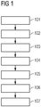
- FIG. 1 shows schematically and by way of example a sequence of the method according to the invention for monitoring, controlling and controlled shutdown of control and / or computer units of at least one installation.
- the control and / or computer units of the at least one system of power supply components of the at least one system are supplied with energy.
- a control application is installed in an installation process 101 on the control and / or computer units.
- a connection is established, for example, between the at least one installation or between the power supply components and installed control applications of the at least one installation and a control system for power supply components via a communication network (eg Ethernet).
- a communication network eg Ethernet
- the power supply components and the control and / or computer units with the installed control applications should also have a connection to the communication network (eg Ethernet).
- control system for power supply components
- a control system for example, a control system can be used, as in the hitherto unpublished European patent application EP 18156846.0 described.
- a control system comprises a central server unit with associated database, local server units which are dedicated to the power supply components of the at least one system, and client units to each local server unit.
- the control system for power supply components sends out a detection call via the communication network.
- the power supply components connected to the communication network and the control applications available on the control and / or computer units are addressed by the detection call.
- the sending of the detection call is carried out, for example, in the form of a so-called multicast, whereby, for example, the so-called Discovery and Configuration Protocol or DCP for short is used.
- the power supply components and the control applications for example, response messages with unique identification data (eg MAC address of the power supply component or the control and / or computer unit of the control application, a device name and / or identifier, an IP address, etc.) are sent back to the control system, thus identifying the power supply components and control applications.
- unique identification data eg MAC address of the power supply component or the control and / or computer unit of the control application, a device name and / or identifier, an IP address, etc.
- a client unit for communication between the respectively identified control application and the control system in particular the central server unit of the control system for power supply components, can be created in each case in the control system for power supply components.
- a template unit - a so-called template - can be used to create the client unit.
- the control application then takes over the function of the local server unit for the communication to the respectively generated client unit.
- the identified power supply components and control applications of the at least one system can then be displayed and / or output for a mapping operation 104, for example via an input / output unit.
- the input / output unit may be connected to the control system for power supply components e.g. be connected by means of an application or web application.
- the identified power supply components and control applications are then displayed, for example, in a standard web browser as a user interface, without limitation, e.g. a stationary PC, stationary PC systems and / or mobile terminals (e.g., tablet PC, handheld, etc.) can be used for the input / output unit.
- the identified power supply components are then assigned the respective identified control applications.
- a power supply component identified by the control system is assigned at least one control application which is installed on a control and / or computer unit powered by this power supply component.
- a Power supply component eg power supply or uninterruptible power supply
- control applications can be assigned to this power supply component.
- the failure of the power supply in one plant section or plant may have an effect on a preceding and / or following plant section or a preceding and / or following plant such that in the preceding and / or following section of the plant or in the preceding and / or or following installation control and / or computer units - if necessary, despite functioning power supply - must be shut down.
- buffer times such as e.g. a so-called dead time (waiting for the control application without action), a waiting time (preparing a shutdown by the control application), etc.
- actions such as no action in the dead time, initiate energy saving measures in buffer operation of the power supply, termination of applications, storage of data, shutdown of the control and / or computer unit, etc. individually or as a sequence to be executed (eg in the form of a so-called batch) certain event alarms be assigned to.
- the input of the configuration parameters and / or the predefinable action of the respective control application can be like the assignment be made via the input / output unit.
- the settings (parameters, actions) of the respective control application can be displayed, for example, by means of the web application or via the web browser. Furthermore, plausibility checks of the entries can be carried out.
- an authentication e.g. be provided by username and password.
- a range of displayed data e.g., power supply components, control applications, parameters, etc.
- permissible configuration options e.g., only display / read access, feasible associations, parameter changes, etc.
- standard or default values and / or default actions can be specified by the control system.
- the allocation process 104 the allocations between the power supply components and the control applications and optionally made configurations of the control applications are then stored in a storage process 105.
- a monitoring process 106 the power supply components are then monitored for occurring event alarms.
- the storage of the allocations in the storage process 105 and the monitoring of the power supply components to event alarms in the monitoring process 106 can in one embodiment of the method according to the invention - such as in FIG. 2 shown centrally in the control system for power supply components, the control system in this variant permanent communication links having the power supply components and the control applications eg by means of OPC UA interface.
- the storage of the allocations in the storage process 105 and the monitoring of the power supply components in the monitoring process 106 - such as in the in FIG. 3 exemplified embodiment of the method according to the invention - done locally in the respective control application.
- the connection of the control system for power supply components is separated via the communication network to the power supply components and control applications.
- a communication network eg Ethernet
- the power supply component can have a local server unit and a client function can be adopted by the control application.
- an execution procedure 107 when an event alarm occurs (eg, power supply in buffering, low battery, overheating of the power supply component, shutdown of the power supply, etc.) in a power supply component of all the control application associated with that power supply component, the corresponding presettable or configuration is established initiated actions on the associated control and / or computer unit.
- the actions can be executed, for example, as a command-line-based application or as a so-called batch file, in particular if several actions are to be run through.
- the control application may e.g. an alarm or alarm message is sent to an input / output unit.
- the controlled control and / or computer units are controlled and shut down, for example, taking into account the respective shutdown or shut-down times.
- the affected control and / or computer units can be restarted again, for example, by emitting a voltage pulse, for example by a special event alarm (eg "power supply available again").
- FIG. 2 exemplified an embodiment of the method according to the invention, in which a central monitoring of the power supply components SV1, SV2 is provided and there is a permanent communication connection to the control system SYS for power supply components SV1, SV2.
- FIG. 2 shows an exemplary system AN, which includes two power supply components SV1, SV2, for example.
- control and / or computer units SE1, SE2, SE3 are supplied with energy from the power supply components SV1, SV2.
- a first power supply component SV1 supplies a first and second control and / or computer units SE1, SE2 with energy and, for example, a third power and control unit and / or computer unit SE3 from a second power supply component SV2.
- a control application SD1, SD2, SD3 is respectively installed on the control and / or computer units SE1, SE2, SE3.
- a communication connection to the control system SYS for power supply components SV1, SV2 is established via a communication network.
- the control system SYS can be connected to the communication network (eg Ethernet) to which the system AN or the power supply components SV1, SV2 and the control and / or computer units SE1, SE2, SE3 are connected.
- the control system SYS sends out a detection call DE (eg a multicast by means of a DCP protocol) via the communication network.
- On the detection call DE are of the power supply components SV1, SV2 and of the On the control and / or computer units SE1, SE2, SE3 installed control applications SD1, SD2, SD3 sent response messages to the control system SYS and thus the power supply components SV1, SV2 and the control applications identified SD1, SD2, SD3 on the control system SYS.
- the association between the identified power supply components SV1, SV2 and the identified control applications SD1, SD2, SD3 of the exemplary system AN is then performed.
- the first power supply component SV1 is assigned the control applications SD1, SD2, which are installed on the control and / or computer units SE1, SE2 supplied by the first power supply component SV1, SV2.
- the second power supply component SV2 is e.g. associated with the control application SD3, which is installed on the supplied from the second power supply component SV2 control and / or computer unit SE3.
- the control application SD3 installed on the third control and / or computer unit SE3 can also be assigned, for example, to the first power supply component SV1. Analogously, this also applies to the control applications SD1, SD2 installed on the first and / or second control and / or computer unit SE1, SE2, if a fault in the second power supply component SV2 also affects these control and / or computer units SE1, SE2 should have an indirect effect.
- the assignment between the power supply components SV1, SV2 and the control applications SD1, SD2, SD3 and possibly an input of configuration parameters and / or predefinable actions for the control applications SD1, SD2, SD3 in the assignment process 204 can be carried out, for example, via an input / output unit AE, which is connected to the control system SYS.
- the allocations in the storage process 205 are stored centrally in the control system SYS for power supply components SV1, SV2.
- the central server unit associated database are used.
- configurations of the control applications SD1, SD2, SD3 can also be stored centrally, for example, and / or transmitted to the respective control applications SD1, SD2, SD3 via the communication network, for example by means of an OPC-UA interface.
- the power supply components SV1, SV2 are then monitored centrally by the control system SYS via the existing communication link (e.g., by means of OPC-UA) for the occurrence of disturbances in the power supply and associated event alarms.
- the control system may collect and store event alarm data for diagnostic purposes during the monitoring process 206. A query and evaluation of these data can be performed, for example, via the attached to the control system SYS input / output unit AE.
- control applications SD1, SD2, SD3 are addressed by the control system SYS based on the stored assignments.
- the respective predetermined or configured actions are initiated in the execution process 207 on the respectively associated control and / or computer units SE1, SE2, SE3.
- the associated control and / or computer units SE1, SE2, SE3 can shut down in a controlled manner.
- control applications SD1, SD2, SD3 may, for example, issue alarms be sent, which can be displayed for example on the input / output unit AE or eg a service employee can be issued on a mobile device.
- Changes or adaptations of the configurations of the control applications SD1, SD2, SD3 can be made, for example, via the control system SYS or via the input / output unit AE connected to the control system SYS .
- the changes and adjustments can also be stored centrally in the control system SYS and, if necessary, forwarded to the respective control application SD1, SD2, SD3 for processing.
- FIG. 3 shows an example of an embodiment of the method according to the invention, in which a local monitoring of the power supply components SV1, SV2 is provided.
- a local monitoring of the power supply components SV1, SV2 is provided.
- no permanent communication connection to the control system SYS for power supply components SV1, SV2 is necessary.
- FIG. 3 again shows the exemplary system AN with exemplary two power supply components SV1, SV2, again exemplified by the first power supply component SV1, the first and second control and / or computer units SE1, SE2 and the second power supply component SV2, the third control and / or computer unit SE3 be energized.
- a control application SD1, SD2, SD3 is respectively installed on the control and / or computer units SE1, SE2, SE3, and a communication connection to the control system SYS for power supply components SV1, SV2 is set up in the process of communication setup 302 via a communication network.
- the control system SYS sends out a detection call DE (eg a multicast by means of a DCP protocol) via the communication network.
- a detection call DE eg a multicast by means of a DCP protocol
- On the detection call DE are sent from the power supply components SV1, SV2 and of the control and / or computer units SE1, SE2, SE3 control applications SD1, SD2, SD3 response messages to the control system SYS and thus the power supply components SV1, SV2 and the control applications SD1, SD2, SD3 identified at the control system SYS.
- the assignment process 304 again an association takes place between the identified power supply components SV1, SV2 and the identified control applications SD1, SD2, SD3 of the exemplary system AN.
- the assignment and optionally a configuration of the control applications SD1, SD2, SD3 (input of configuration parameters and actions) can be carried out, for example, via the input / output unit AE connected to the control system SYS.
- the entered assignments between the identified power supply components SV1, SV2 and the identified control applications SD1, SD2, SD3 are first transferred in a memory process 305 from the control system SYS to the respective control applications SD1, SD2, SD3 and power supply components SV1, SV2.
- an OPC UA interface can be used for the communication.
- the respective assignments are stored locally at the respective control application SD1, SD2, SD3 and / or on the respective power supply component SV1, SV2.
- configuration parameters and / or actions entered in the assignment process 304 are likewise transmitted to the respective control application SD1, SD2, SD3 and stored locally.
- the communication connection of the control system SYS to the communication network or to the power supply components SV1, SV2 and to the control and computer units SE1, SE2, SE3 or the associated control applications SD1, SD2, SD3 can be disconnected.
- the power supply components SV1, SV2 are then monitored locally by the respectively assigned control applications SD1, SD2, SD3 via the respective communication connection for occurrence of event alarms. That the first power supply is e.g. monitored by the associated control applications SD1, SD2 of the first and second control and computer units SE1, SE2.
- the second power supply component SV2 is monitored, for example, by the associated control application SD3 of the third control and / or computer unit SE3.
- the first and second power supplies SV1, SV2 have local server units or server functions and the associated control applications SD1, SD2, SD3 e.g. act as a client unit.
- SV2 Upon occurrence of an event alarm on the first and / or the second power supply component SV1, SV2 are then introduced by the respective control applications SD1, SD2, SD3 in the execution process 307, the respective predetermined actions on the associated control and computer unit SE1, SE2, SE3 and if necessary during prolonged interruption of Power the respective control and computer unit SE1, SE2, SE3 shut down controlled. From the respective control application SD1, SD2, SD3, for example, in the execution process 307, an alarm or an alarm message can be issued locally.
- a change of configuration parameters and given actions for certain event alarms can, for example, be made locally at the respective control application SD1, SD2, SD3.
- a local input / output unit LAE can be used, and e.g. a configuration of the corresponding control application SD1 be changed or adapted.
Landscapes
- Engineering & Computer Science (AREA)
- Theoretical Computer Science (AREA)
- Physics & Mathematics (AREA)
- General Physics & Mathematics (AREA)
- General Engineering & Computer Science (AREA)
- Automation & Control Theory (AREA)
- Computer Hardware Design (AREA)
- Computing Systems (AREA)
- Power Sources (AREA)
- Remote Monitoring And Control Of Power-Distribution Networks (AREA)
Priority Applications (3)
| Application Number | Priority Date | Filing Date | Title |
|---|---|---|---|
| EP18156871.8A EP3528065B1 (fr) | 2018-02-15 | 2018-02-15 | Procédé de surveillance, de commande et de mise hors tension contrôlée des unités de commande et/ou des unités informatiques |
| US16/275,475 US11093014B2 (en) | 2018-02-15 | 2019-02-14 | Method for monitoring, control and graceful shutdown of control and/or computer units |
| CN201910116930.6A CN110162160B (zh) | 2018-02-15 | 2019-02-15 | 监控、控制和受监督地关机控制和/或计算机单元的方法 |
Applications Claiming Priority (1)
| Application Number | Priority Date | Filing Date | Title |
|---|---|---|---|
| EP18156871.8A EP3528065B1 (fr) | 2018-02-15 | 2018-02-15 | Procédé de surveillance, de commande et de mise hors tension contrôlée des unités de commande et/ou des unités informatiques |
Publications (2)
| Publication Number | Publication Date |
|---|---|
| EP3528065A1 true EP3528065A1 (fr) | 2019-08-21 |
| EP3528065B1 EP3528065B1 (fr) | 2021-08-18 |
Family
ID=61244384
Family Applications (1)
| Application Number | Title | Priority Date | Filing Date |
|---|---|---|---|
| EP18156871.8A Active EP3528065B1 (fr) | 2018-02-15 | 2018-02-15 | Procédé de surveillance, de commande et de mise hors tension contrôlée des unités de commande et/ou des unités informatiques |
Country Status (3)
| Country | Link |
|---|---|
| US (1) | US11093014B2 (fr) |
| EP (1) | EP3528065B1 (fr) |
| CN (1) | CN110162160B (fr) |
Cited By (1)
| Publication number | Priority date | Publication date | Assignee | Title |
|---|---|---|---|---|
| WO2024081489A1 (fr) * | 2022-10-14 | 2024-04-18 | Caterpillar Inc. | Contrôleur de mode de système modulaire et procédés associés |
Families Citing this family (1)
| Publication number | Priority date | Publication date | Assignee | Title |
|---|---|---|---|---|
| US11031804B2 (en) * | 2017-11-06 | 2021-06-08 | Nxp B.V. | Power controller |
Citations (4)
| Publication number | Priority date | Publication date | Assignee | Title |
|---|---|---|---|---|
| EP1832955A1 (fr) | 2006-03-10 | 2007-09-12 | Densei Lambda K.K. | Alimentation électrique sans coupure, système d'alimentation électrique sans coupure et support de stockage |
| EP2869154A1 (fr) * | 2013-10-31 | 2015-05-06 | Rockwell Automation Technologies, Inc. | Fonctionnement indépendant de matériel de commande et système de surveillance dans un contrôleur d'automatisation |
| EP2787405B1 (fr) | 2013-04-05 | 2017-07-19 | Siemens Aktiengesellschaft | Procédé de fonctionnement d'une installation électrique et installation électrique |
| EP2876778B1 (fr) | 2013-11-22 | 2017-08-02 | Siemens Aktiengesellschaft | Installation électrique dotée d'une unité d'alimentation électrique sans coupure |
Family Cites Families (9)
| Publication number | Priority date | Publication date | Assignee | Title |
|---|---|---|---|---|
| US20020129355A1 (en) * | 2001-03-01 | 2002-09-12 | Mike Velten | Method and system for monitoring an apparatus for a computer |
| US7469363B2 (en) * | 2002-07-29 | 2008-12-23 | Baumuller Anlagen-Systemtech-Nik Gmbh & Co. | Computer network with diagnosis computer nodes |
| US7275169B2 (en) * | 2003-11-03 | 2007-09-25 | American Power Conversion Corporation | Graphical view of shutdown process |
| US7296172B2 (en) * | 2004-08-24 | 2007-11-13 | Inventec Corporation | Power control and management method for uninterruptible power system and servers |
| US7590653B2 (en) * | 2005-03-02 | 2009-09-15 | Cassatt Corporation | Automated discovery and inventory of nodes within an autonomic distributed computing system |
| US8635484B2 (en) * | 2009-03-18 | 2014-01-21 | Hewlett-Packard Development Company, L.P. | Event based correlation of power events |
| US9360908B2 (en) * | 2012-12-12 | 2016-06-07 | Lenovo Enterprise Solutions (Singapore) Pte. Ltd. | Sequential power up of devices in a computing cluster based on device function |
| US10225153B2 (en) * | 2016-04-18 | 2019-03-05 | International Business Machines Corporation | Node discovery mechanisms in a switchless network |
| US10205628B2 (en) * | 2016-06-07 | 2019-02-12 | Time Warner Cable Enterprises Llc | Methods and apparatus for determining and/or controlling backup power in a communications system |
-
2018
- 2018-02-15 EP EP18156871.8A patent/EP3528065B1/fr active Active
-
2019
- 2019-02-14 US US16/275,475 patent/US11093014B2/en active Active
- 2019-02-15 CN CN201910116930.6A patent/CN110162160B/zh active Active
Patent Citations (4)
| Publication number | Priority date | Publication date | Assignee | Title |
|---|---|---|---|---|
| EP1832955A1 (fr) | 2006-03-10 | 2007-09-12 | Densei Lambda K.K. | Alimentation électrique sans coupure, système d'alimentation électrique sans coupure et support de stockage |
| EP2787405B1 (fr) | 2013-04-05 | 2017-07-19 | Siemens Aktiengesellschaft | Procédé de fonctionnement d'une installation électrique et installation électrique |
| EP2869154A1 (fr) * | 2013-10-31 | 2015-05-06 | Rockwell Automation Technologies, Inc. | Fonctionnement indépendant de matériel de commande et système de surveillance dans un contrôleur d'automatisation |
| EP2876778B1 (fr) | 2013-11-22 | 2017-08-02 | Siemens Aktiengesellschaft | Installation électrique dotée d'une unité d'alimentation électrique sans coupure |
Cited By (2)
| Publication number | Priority date | Publication date | Assignee | Title |
|---|---|---|---|---|
| WO2024081489A1 (fr) * | 2022-10-14 | 2024-04-18 | Caterpillar Inc. | Contrôleur de mode de système modulaire et procédés associés |
| US12281462B2 (en) | 2022-10-14 | 2025-04-22 | Caterpillar Inc. | Modular system mode controller and related methods |
Also Published As
| Publication number | Publication date |
|---|---|
| CN110162160B (zh) | 2023-11-28 |
| EP3528065B1 (fr) | 2021-08-18 |
| CN110162160A (zh) | 2019-08-23 |
| US20190250687A1 (en) | 2019-08-15 |
| US11093014B2 (en) | 2021-08-17 |
Similar Documents
| Publication | Publication Date | Title |
|---|---|---|
| EP3560150B1 (fr) | Surveillance de la transmission de données dans un système d'accès à des appareils sur une base client serveur | |
| DE102012003242A1 (de) | Verfahren zum ausfallsicheren Betreiben eines Prozesssteuersystems mit redundanten Steuereinrichtungen | |
| DE19744071B4 (de) | Eine programmierbare Logiksteuervorrichtung verwendendes Steuerungssystem | |
| EP3547618A1 (fr) | Procédé d'établissement d'une connexion de communication redondante et unité de commande sécurisée | |
| EP2684335B1 (fr) | Installation d'automatisation d'énergie et procédé servant à faire fonctionner une installation d'automatisation d'énergie | |
| CN109257564A (zh) | 一种电气设备运行状态监控系统 | |
| EP2491492B1 (fr) | Système d'automatisation et procédé pour faire fonctionner un système d'automatisation | |
| EP3528064A1 (fr) | Système de commande et procédé associé de mise en marche, de commande et de surveillance pour des éléments d'alimentation électrique | |
| EP3113461B1 (fr) | Procédé d'établissement de liaisons de communication à des appareils de commande à fonctionnement redondant d'un système d'automatisation industrielle et appareil de commande | |
| EP3528065B1 (fr) | Procédé de surveillance, de commande et de mise hors tension contrôlée des unités de commande et/ou des unités informatiques | |
| EP2266002A1 (fr) | Procédé d utilisation d une commande de sécurité et réseau d automatisation doté d une telle commande de sécurité | |
| EP3602732B1 (fr) | Procédé de fonctionnement d'une installation électrique comprenant une pluralité de consommateurs électriques, alimentation électrique et installation électrique | |
| EP2798418B1 (fr) | Dispositif et procédé de constitution automatique de séquences de mise en fonctionnement dans une installation | |
| DE102011077787A1 (de) | System zum Zugriff von zumindest einem Client auf zumindest ein Feldgerät | |
| DE102023115224A1 (de) | Einrichtungen und verfahren für nicht-störendes ersetzen von simplex-e/a-komponenten | |
| DE102013109090B9 (de) | Energieverteilungseinheit, Computeranordnung und Verfahren zum Erfassen von Anschlussinformationen | |
| DE102023104376A1 (de) | Verfahren zum Betrieb eines elektrochirurgischen Generators | |
| EP3851923A1 (fr) | Système de guidage pour installations technique pourvu de gestion de certificats | |
| DE102009047864A1 (de) | Automatisierungssystem und Verfahren zum Betrieb eines Automatisierungssystems | |
| EP1426862B1 (fr) | Synchronisation de traitement de données dans des unités de traitement redondantes d'un système de traitement de données | |
| DE102024105515A1 (de) | Eingabe/ausgabe-modul-schnittstelle mit stromsparmodus | |
| DE112004002933B4 (de) | Vorrichtung zum Steuern des Energieflusses zwischen einem Energieversorgungsnetz und einer daran angeschlossenen elektrischen Einrichtung | |
| EP1251645A2 (fr) | Station de lignes d'alimentation et systéme modulaire de lignes d'alimentation pour commander au moins un appareil de télécommunications | |
| EP4300220A1 (fr) | Procédé de communication de sécurité, dispositif de communication, système de communication de sécurité et système de commande | |
| EP3026514B1 (fr) | Installation d'automatisation et procédé de commande externe d'un algorithme d'autocontrôle dans un dispositif de sécurité décentralisé |
Legal Events
| Date | Code | Title | Description |
|---|---|---|---|
| PUAI | Public reference made under article 153(3) epc to a published international application that has entered the european phase |
Free format text: ORIGINAL CODE: 0009012 |
|
| STAA | Information on the status of an ep patent application or granted ep patent |
Free format text: STATUS: THE APPLICATION HAS BEEN PUBLISHED |
|
| AK | Designated contracting states |
Kind code of ref document: A1 Designated state(s): AL AT BE BG CH CY CZ DE DK EE ES FI FR GB GR HR HU IE IS IT LI LT LU LV MC MK MT NL NO PL PT RO RS SE SI SK SM TR |
|
| AX | Request for extension of the european patent |
Extension state: BA ME |
|
| STAA | Information on the status of an ep patent application or granted ep patent |
Free format text: STATUS: REQUEST FOR EXAMINATION WAS MADE |
|
| STAA | Information on the status of an ep patent application or granted ep patent |
Free format text: STATUS: EXAMINATION IS IN PROGRESS |
|
| 17P | Request for examination filed |
Effective date: 20200205 |
|
| RBV | Designated contracting states (corrected) |
Designated state(s): AL AT BE BG CH CY CZ DE DK EE ES FI FR GB GR HR HU IE IS IT LI LT LU LV MC MK MT NL NO PL PT RO RS SE SI SK SM TR |
|
| 17Q | First examination report despatched |
Effective date: 20200226 |
|
| GRAP | Despatch of communication of intention to grant a patent |
Free format text: ORIGINAL CODE: EPIDOSNIGR1 |
|
| STAA | Information on the status of an ep patent application or granted ep patent |
Free format text: STATUS: GRANT OF PATENT IS INTENDED |
|
| GRAJ | Information related to disapproval of communication of intention to grant by the applicant or resumption of examination proceedings by the epo deleted |
Free format text: ORIGINAL CODE: EPIDOSDIGR1 |
|
| STAA | Information on the status of an ep patent application or granted ep patent |
Free format text: STATUS: EXAMINATION IS IN PROGRESS |
|
| INTG | Intention to grant announced |
Effective date: 20210215 |
|
| GRAP | Despatch of communication of intention to grant a patent |
Free format text: ORIGINAL CODE: EPIDOSNIGR1 |
|
| STAA | Information on the status of an ep patent application or granted ep patent |
Free format text: STATUS: GRANT OF PATENT IS INTENDED |
|
| INTC | Intention to grant announced (deleted) | ||
| INTG | Intention to grant announced |
Effective date: 20210319 |
|
| GRAS | Grant fee paid |
Free format text: ORIGINAL CODE: EPIDOSNIGR3 |
|
| GRAA | (expected) grant |
Free format text: ORIGINAL CODE: 0009210 |
|
| STAA | Information on the status of an ep patent application or granted ep patent |
Free format text: STATUS: THE PATENT HAS BEEN GRANTED |
|
| AK | Designated contracting states |
Kind code of ref document: B1 Designated state(s): AL AT BE BG CH CY CZ DE DK EE ES FI FR GB GR HR HU IE IS IT LI LT LU LV MC MK MT NL NO PL PT RO RS SE SI SK SM TR |
|
| REG | Reference to a national code |
Ref country code: GB Ref legal event code: FG4D Free format text: NOT ENGLISH |
|
| REG | Reference to a national code |
Ref country code: CH Ref legal event code: EP |
|
| REG | Reference to a national code |
Ref country code: DE Ref legal event code: R096 Ref document number: 502018006598 Country of ref document: DE |
|
| REG | Reference to a national code |
Ref country code: IE Ref legal event code: FG4D Free format text: LANGUAGE OF EP DOCUMENT: GERMAN Ref country code: AT Ref legal event code: REF Ref document number: 1422187 Country of ref document: AT Kind code of ref document: T Effective date: 20210915 |
|
| REG | Reference to a national code |
Ref country code: LT Ref legal event code: MG9D |
|
| REG | Reference to a national code |
Ref country code: NL Ref legal event code: MP Effective date: 20210818 |
|
| PG25 | Lapsed in a contracting state [announced via postgrant information from national office to epo] |
Ref country code: SE Free format text: LAPSE BECAUSE OF FAILURE TO SUBMIT A TRANSLATION OF THE DESCRIPTION OR TO PAY THE FEE WITHIN THE PRESCRIBED TIME-LIMIT Effective date: 20210818 Ref country code: RS Free format text: LAPSE BECAUSE OF FAILURE TO SUBMIT A TRANSLATION OF THE DESCRIPTION OR TO PAY THE FEE WITHIN THE PRESCRIBED TIME-LIMIT Effective date: 20210818 Ref country code: HR Free format text: LAPSE BECAUSE OF FAILURE TO SUBMIT A TRANSLATION OF THE DESCRIPTION OR TO PAY THE FEE WITHIN THE PRESCRIBED TIME-LIMIT Effective date: 20210818 Ref country code: ES Free format text: LAPSE BECAUSE OF FAILURE TO SUBMIT A TRANSLATION OF THE DESCRIPTION OR TO PAY THE FEE WITHIN THE PRESCRIBED TIME-LIMIT Effective date: 20210818 Ref country code: FI Free format text: LAPSE BECAUSE OF FAILURE TO SUBMIT A TRANSLATION OF THE DESCRIPTION OR TO PAY THE FEE WITHIN THE PRESCRIBED TIME-LIMIT Effective date: 20210818 Ref country code: NO Free format text: LAPSE BECAUSE OF FAILURE TO SUBMIT A TRANSLATION OF THE DESCRIPTION OR TO PAY THE FEE WITHIN THE PRESCRIBED TIME-LIMIT Effective date: 20211118 Ref country code: PT Free format text: LAPSE BECAUSE OF FAILURE TO SUBMIT A TRANSLATION OF THE DESCRIPTION OR TO PAY THE FEE WITHIN THE PRESCRIBED TIME-LIMIT Effective date: 20211220 Ref country code: LT Free format text: LAPSE BECAUSE OF FAILURE TO SUBMIT A TRANSLATION OF THE DESCRIPTION OR TO PAY THE FEE WITHIN THE PRESCRIBED TIME-LIMIT Effective date: 20210818 Ref country code: BG Free format text: LAPSE BECAUSE OF FAILURE TO SUBMIT A TRANSLATION OF THE DESCRIPTION OR TO PAY THE FEE WITHIN THE PRESCRIBED TIME-LIMIT Effective date: 20211118 |
|
| PG25 | Lapsed in a contracting state [announced via postgrant information from national office to epo] |
Ref country code: PL Free format text: LAPSE BECAUSE OF FAILURE TO SUBMIT A TRANSLATION OF THE DESCRIPTION OR TO PAY THE FEE WITHIN THE PRESCRIBED TIME-LIMIT Effective date: 20210818 Ref country code: LV Free format text: LAPSE BECAUSE OF FAILURE TO SUBMIT A TRANSLATION OF THE DESCRIPTION OR TO PAY THE FEE WITHIN THE PRESCRIBED TIME-LIMIT Effective date: 20210818 Ref country code: GR Free format text: LAPSE BECAUSE OF FAILURE TO SUBMIT A TRANSLATION OF THE DESCRIPTION OR TO PAY THE FEE WITHIN THE PRESCRIBED TIME-LIMIT Effective date: 20211119 |
|
| PG25 | Lapsed in a contracting state [announced via postgrant information from national office to epo] |
Ref country code: NL Free format text: LAPSE BECAUSE OF FAILURE TO SUBMIT A TRANSLATION OF THE DESCRIPTION OR TO PAY THE FEE WITHIN THE PRESCRIBED TIME-LIMIT Effective date: 20210818 |
|
| PG25 | Lapsed in a contracting state [announced via postgrant information from national office to epo] |
Ref country code: DK Free format text: LAPSE BECAUSE OF FAILURE TO SUBMIT A TRANSLATION OF THE DESCRIPTION OR TO PAY THE FEE WITHIN THE PRESCRIBED TIME-LIMIT Effective date: 20210818 |
|
| REG | Reference to a national code |
Ref country code: DE Ref legal event code: R097 Ref document number: 502018006598 Country of ref document: DE |
|
| PG25 | Lapsed in a contracting state [announced via postgrant information from national office to epo] |
Ref country code: SM Free format text: LAPSE BECAUSE OF FAILURE TO SUBMIT A TRANSLATION OF THE DESCRIPTION OR TO PAY THE FEE WITHIN THE PRESCRIBED TIME-LIMIT Effective date: 20210818 Ref country code: SK Free format text: LAPSE BECAUSE OF FAILURE TO SUBMIT A TRANSLATION OF THE DESCRIPTION OR TO PAY THE FEE WITHIN THE PRESCRIBED TIME-LIMIT Effective date: 20210818 Ref country code: RO Free format text: LAPSE BECAUSE OF FAILURE TO SUBMIT A TRANSLATION OF THE DESCRIPTION OR TO PAY THE FEE WITHIN THE PRESCRIBED TIME-LIMIT Effective date: 20210818 Ref country code: EE Free format text: LAPSE BECAUSE OF FAILURE TO SUBMIT A TRANSLATION OF THE DESCRIPTION OR TO PAY THE FEE WITHIN THE PRESCRIBED TIME-LIMIT Effective date: 20210818 Ref country code: CZ Free format text: LAPSE BECAUSE OF FAILURE TO SUBMIT A TRANSLATION OF THE DESCRIPTION OR TO PAY THE FEE WITHIN THE PRESCRIBED TIME-LIMIT Effective date: 20210818 Ref country code: AL Free format text: LAPSE BECAUSE OF FAILURE TO SUBMIT A TRANSLATION OF THE DESCRIPTION OR TO PAY THE FEE WITHIN THE PRESCRIBED TIME-LIMIT Effective date: 20210818 |
|
| PLBE | No opposition filed within time limit |
Free format text: ORIGINAL CODE: 0009261 |
|
| STAA | Information on the status of an ep patent application or granted ep patent |
Free format text: STATUS: NO OPPOSITION FILED WITHIN TIME LIMIT |
|
| 26N | No opposition filed |
Effective date: 20220519 |
|
| PG25 | Lapsed in a contracting state [announced via postgrant information from national office to epo] |
Ref country code: IT Free format text: LAPSE BECAUSE OF FAILURE TO SUBMIT A TRANSLATION OF THE DESCRIPTION OR TO PAY THE FEE WITHIN THE PRESCRIBED TIME-LIMIT Effective date: 20210818 |
|
| PG25 | Lapsed in a contracting state [announced via postgrant information from national office to epo] |
Ref country code: SI Free format text: LAPSE BECAUSE OF FAILURE TO SUBMIT A TRANSLATION OF THE DESCRIPTION OR TO PAY THE FEE WITHIN THE PRESCRIBED TIME-LIMIT Effective date: 20210818 |
|
| PG25 | Lapsed in a contracting state [announced via postgrant information from national office to epo] |
Ref country code: MC Free format text: LAPSE BECAUSE OF FAILURE TO SUBMIT A TRANSLATION OF THE DESCRIPTION OR TO PAY THE FEE WITHIN THE PRESCRIBED TIME-LIMIT Effective date: 20210818 |
|
| REG | Reference to a national code |
Ref country code: CH Ref legal event code: PL |
|
| REG | Reference to a national code |
Ref country code: BE Ref legal event code: MM Effective date: 20220228 |
|
| GBPC | Gb: european patent ceased through non-payment of renewal fee |
Effective date: 20220215 |
|
| PG25 | Lapsed in a contracting state [announced via postgrant information from national office to epo] |
Ref country code: LU Free format text: LAPSE BECAUSE OF NON-PAYMENT OF DUE FEES Effective date: 20220215 |
|
| PG25 | Lapsed in a contracting state [announced via postgrant information from national office to epo] |
Ref country code: FR Free format text: LAPSE BECAUSE OF NON-PAYMENT OF DUE FEES Effective date: 20220228 |
|
| PG25 | Lapsed in a contracting state [announced via postgrant information from national office to epo] |
Ref country code: LI Free format text: LAPSE BECAUSE OF NON-PAYMENT OF DUE FEES Effective date: 20220228 Ref country code: IE Free format text: LAPSE BECAUSE OF NON-PAYMENT OF DUE FEES Effective date: 20220215 Ref country code: GB Free format text: LAPSE BECAUSE OF NON-PAYMENT OF DUE FEES Effective date: 20220215 Ref country code: CH Free format text: LAPSE BECAUSE OF NON-PAYMENT OF DUE FEES Effective date: 20220228 |
|
| PG25 | Lapsed in a contracting state [announced via postgrant information from national office to epo] |
Ref country code: BE Free format text: LAPSE BECAUSE OF NON-PAYMENT OF DUE FEES Effective date: 20220228 |
|
| REG | Reference to a national code |
Ref country code: AT Ref legal event code: MM01 Ref document number: 1422187 Country of ref document: AT Kind code of ref document: T Effective date: 20230215 |
|
| PG25 | Lapsed in a contracting state [announced via postgrant information from national office to epo] |
Ref country code: AT Free format text: LAPSE BECAUSE OF NON-PAYMENT OF DUE FEES Effective date: 20230215 |
|
| PG25 | Lapsed in a contracting state [announced via postgrant information from national office to epo] |
Ref country code: MK Free format text: LAPSE BECAUSE OF FAILURE TO SUBMIT A TRANSLATION OF THE DESCRIPTION OR TO PAY THE FEE WITHIN THE PRESCRIBED TIME-LIMIT Effective date: 20210818 Ref country code: CY Free format text: LAPSE BECAUSE OF FAILURE TO SUBMIT A TRANSLATION OF THE DESCRIPTION OR TO PAY THE FEE WITHIN THE PRESCRIBED TIME-LIMIT Effective date: 20210818 Ref country code: AT Free format text: LAPSE BECAUSE OF NON-PAYMENT OF DUE FEES Effective date: 20230215 |
|
| PG25 | Lapsed in a contracting state [announced via postgrant information from national office to epo] |
Ref country code: HU Free format text: LAPSE BECAUSE OF FAILURE TO SUBMIT A TRANSLATION OF THE DESCRIPTION OR TO PAY THE FEE WITHIN THE PRESCRIBED TIME-LIMIT; INVALID AB INITIO Effective date: 20180215 |
|
| PG25 | Lapsed in a contracting state [announced via postgrant information from national office to epo] |
Ref country code: TR Free format text: LAPSE BECAUSE OF FAILURE TO SUBMIT A TRANSLATION OF THE DESCRIPTION OR TO PAY THE FEE WITHIN THE PRESCRIBED TIME-LIMIT Effective date: 20210818 |
|
| PG25 | Lapsed in a contracting state [announced via postgrant information from national office to epo] |
Ref country code: MT Free format text: LAPSE BECAUSE OF FAILURE TO SUBMIT A TRANSLATION OF THE DESCRIPTION OR TO PAY THE FEE WITHIN THE PRESCRIBED TIME-LIMIT Effective date: 20210818 |
|
| PGFP | Annual fee paid to national office [announced via postgrant information from national office to epo] |
Ref country code: DE Payment date: 20250417 Year of fee payment: 8 |
|
| PGFP | Annual fee paid to national office [announced via postgrant information from national office to epo] |
Ref country code: AT Payment date: 20260410 Year of fee payment: 5 |