EP3528558B1 - Procédé d'attribution de puissance, procédé de réglage de puissance, terminal et dispositif de réseau d'accès - Google Patents
Procédé d'attribution de puissance, procédé de réglage de puissance, terminal et dispositif de réseau d'accès Download PDFInfo
- Publication number
- EP3528558B1 EP3528558B1 EP17867719.1A EP17867719A EP3528558B1 EP 3528558 B1 EP3528558 B1 EP 3528558B1 EP 17867719 A EP17867719 A EP 17867719A EP 3528558 B1 EP3528558 B1 EP 3528558B1
- Authority
- EP
- European Patent Office
- Prior art keywords
- carrier
- carried
- transmit power
- transmitted
- channel
- Prior art date
- Legal status (The legal status is an assumption and is not a legal conclusion. Google has not performed a legal analysis and makes no representation as to the accuracy of the status listed.)
- Active
Links
Images





Classifications
-
- H—ELECTRICITY
- H04—ELECTRIC COMMUNICATION TECHNIQUE
- H04W—WIRELESS COMMUNICATION NETWORKS
- H04W52/00—Power management, e.g. Transmission Power Control [TPC] or power classes
- H04W52/04—Transmission power control [TPC]
- H04W52/06—TPC algorithms
- H04W52/14—Separate analysis of uplink or downlink
- H04W52/146—Uplink power control
-
- H—ELECTRICITY
- H04—ELECTRIC COMMUNICATION TECHNIQUE
- H04W—WIRELESS COMMUNICATION NETWORKS
- H04W52/00—Power management, e.g. Transmission Power Control [TPC] or power classes
- H04W52/04—Transmission power control [TPC]
- H04W52/30—Transmission power control [TPC] using constraints in the total amount of available transmission power
- H04W52/36—Transmission power control [TPC] using constraints in the total amount of available transmission power with a discrete range or set of values, e.g. step size, ramping or offsets
- H04W52/367—Power values between minimum and maximum limits, e.g. dynamic range
-
- H—ELECTRICITY
- H04—ELECTRIC COMMUNICATION TECHNIQUE
- H04L—TRANSMISSION OF DIGITAL INFORMATION, e.g. TELEGRAPHIC COMMUNICATION
- H04L25/00—Baseband systems
- H04L25/02—Details ; arrangements for supplying electrical power along data transmission lines
- H04L25/0202—Channel estimation
- H04L25/0224—Channel estimation using sounding signals
- H04L25/0226—Channel estimation using sounding signals sounding signals per se
-
- H—ELECTRICITY
- H04—ELECTRIC COMMUNICATION TECHNIQUE
- H04L—TRANSMISSION OF DIGITAL INFORMATION, e.g. TELEGRAPHIC COMMUNICATION
- H04L5/00—Arrangements affording multiple use of the transmission path
- H04L5/003—Arrangements for allocating sub-channels of the transmission path
- H04L5/0048—Allocation of pilot signals, i.e. of signals known to the receiver
- H04L5/0051—Allocation of pilot signals, i.e. of signals known to the receiver of dedicated pilots, i.e. pilots destined for a single user or terminal
-
- H—ELECTRICITY
- H04—ELECTRIC COMMUNICATION TECHNIQUE
- H04W—WIRELESS COMMUNICATION NETWORKS
- H04W52/00—Power management, e.g. Transmission Power Control [TPC] or power classes
- H04W52/04—Transmission power control [TPC]
- H04W52/18—TPC being performed according to specific parameters
- H04W52/28—TPC being performed according to specific parameters using user profile, e.g. mobile speed, priority or network state, e.g. standby, idle or non-transmission
- H04W52/281—TPC being performed according to specific parameters using user profile, e.g. mobile speed, priority or network state, e.g. standby, idle or non-transmission taking into account user or data type priority
-
- H—ELECTRICITY
- H04—ELECTRIC COMMUNICATION TECHNIQUE
- H04W—WIRELESS COMMUNICATION NETWORKS
- H04W52/00—Power management, e.g. Transmission Power Control [TPC] or power classes
- H04W52/04—Transmission power control [TPC]
- H04W52/30—Transmission power control [TPC] using constraints in the total amount of available transmission power
- H04W52/34—TPC management, i.e. sharing limited amount of power among users or channels or data types, e.g. cell loading
- H04W52/346—TPC management, i.e. sharing limited amount of power among users or channels or data types, e.g. cell loading distributing total power among users or channels
-
- H—ELECTRICITY
- H04—ELECTRIC COMMUNICATION TECHNIQUE
- H04W—WIRELESS COMMUNICATION NETWORKS
- H04W72/00—Local resource management
- H04W72/04—Wireless resource allocation
-
- H—ELECTRICITY
- H04—ELECTRIC COMMUNICATION TECHNIQUE
- H04W—WIRELESS COMMUNICATION NETWORKS
- H04W72/00—Local resource management
- H04W72/04—Wireless resource allocation
- H04W72/044—Wireless resource allocation based on the type of the allocated resource
- H04W72/0446—Resources in time domain, e.g. slots or frames
-
- H—ELECTRICITY
- H04—ELECTRIC COMMUNICATION TECHNIQUE
- H04W—WIRELESS COMMUNICATION NETWORKS
- H04W72/00—Local resource management
- H04W72/04—Wireless resource allocation
- H04W72/044—Wireless resource allocation based on the type of the allocated resource
- H04W72/0453—Resources in frequency domain, e.g. a carrier in FDMA
-
- H—ELECTRICITY
- H04—ELECTRIC COMMUNICATION TECHNIQUE
- H04W—WIRELESS COMMUNICATION NETWORKS
- H04W72/00—Local resource management
- H04W72/04—Wireless resource allocation
- H04W72/044—Wireless resource allocation based on the type of the allocated resource
- H04W72/0473—Wireless resource allocation based on the type of the allocated resource the resource being transmission power
-
- H—ELECTRICITY
- H04—ELECTRIC COMMUNICATION TECHNIQUE
- H04W—WIRELESS COMMUNICATION NETWORKS
- H04W72/00—Local resource management
- H04W72/20—Control channels or signalling for resource management
- H04W72/21—Control channels or signalling for resource management in the uplink direction of a wireless link, i.e. towards the network
-
- H—ELECTRICITY
- H04—ELECTRIC COMMUNICATION TECHNIQUE
- H04W—WIRELESS COMMUNICATION NETWORKS
- H04W72/00—Local resource management
- H04W72/20—Control channels or signalling for resource management
- H04W72/23—Control channels or signalling for resource management in the downlink direction of a wireless link, i.e. towards a terminal
-
- H—ELECTRICITY
- H04—ELECTRIC COMMUNICATION TECHNIQUE
- H04W—WIRELESS COMMUNICATION NETWORKS
- H04W72/00—Local resource management
- H04W72/50—Allocation or scheduling criteria for wireless resources
- H04W72/56—Allocation or scheduling criteria for wireless resources based on priority criteria
-
- H—ELECTRICITY
- H04—ELECTRIC COMMUNICATION TECHNIQUE
- H04W—WIRELESS COMMUNICATION NETWORKS
- H04W52/00—Power management, e.g. Transmission Power Control [TPC] or power classes
- H04W52/04—Transmission power control [TPC]
- H04W52/38—TPC being performed in particular situations
-
- H—ELECTRICITY
- H04—ELECTRIC COMMUNICATION TECHNIQUE
- H04W—WIRELESS COMMUNICATION NETWORKS
- H04W52/00—Power management, e.g. Transmission Power Control [TPC] or power classes
- H04W52/04—Transmission power control [TPC]
- H04W52/54—Signalisation aspects of the TPC commands, e.g. frame structure
-
- H—ELECTRICITY
- H04—ELECTRIC COMMUNICATION TECHNIQUE
- H04W—WIRELESS COMMUNICATION NETWORKS
- H04W74/00—Wireless channel access
- H04W74/08—Non-scheduled access, e.g. ALOHA
- H04W74/0833—Random access procedures, e.g. with 4-step access
Definitions
- This application relates to the field of communications technologies, and in particular, to a power allocation method, a power adjustment method, a terminal, and an access network device.
- LTE-A Long Term Evolution Advanced
- 3GPP 3rd Generation Partnership Project
- LTE-A Long Term Evolution Advanced
- CA carrier aggregation
- spectrums of two or more component carriers are aggregated to obtain a larger transmission bandwidth.
- uplink subframes on different carriers overlap with each other. This phenomenon occurs mainly in the following two cases (two carriers are used as an example in all the following descriptions, and a plurality of carriers may be included actually).
- Case 1 There is a relatively large difference between a length of an uplink subframe on a first carrier and a length of an uplink subframe on a second carrier, so that one uplink subframe on the second carrier is corresponding to a plurality of uplink subframes on the first carrier.
- minimum transmission time granularities in other words, minimum time units of data transmission
- a length of a subframe at a high frequency of 28 GHz is 0.3 ms
- a length of a subframe at a low frequency of 2 GHz may be set to 1 ms, and therefore one low-frequency subframe is corresponding to a plurality of high-frequency subframes.
- Case 2 An uplink subframe on a first carrier and an uplink subframe on a second carrier have approximate lengths or identical lengths. However, start time of the uplink subframe on the first carrier and start time of the uplink subframe on the second carrier are different, and therefore there is a location offset between the uplink subframe on the first carrier and the uplink subframe on the second carrier. Consequently, one uplink subframe on the second carrier overlaps two uplink subframes on the first carrier. Specifically, the two carriers belong to two timing advance groups (TAG), and uplink transmit channels on the two carriers have different timing advances. Consequently, uplink subframes on the two carriers have different start time and overlap with each other.
- TAG timing advance groups
- a terminal Before transmitting uplink data in the uplink subframes on the two carriers, a terminal needs to allocate a power to a channel of a corresponding uplink subframe.
- a channel transmit power required by each uplink subframe (in other words, a transmit power of a channel transmitted in the uplink subframe) is determined based on downlink control information (DCI), and then a transmit power of each channel in an overlapping uplink subframe on the two carriers is determined based on priorities of the channels in the overlapping uplink subframe on the two carriers.
- DCI downlink control information
- the terminal may obtain two pieces of DCI corresponding to the two carriers respectively.
- information including power allocation information and the like about a to-be-transmitted channel, in an uplink subframe, to which a power needs to be allocated can be determined based on DCI corresponding to the second carrier.
- the first carrier when the DCI corresponding to the second carrier is obtained, only information about channels in first several (or one) uplink subframes, on the first carrier, that overlap the uplink subframe on the second carrier can be obtained, but information about channels in last several (or one) uplink subframes on the first carrier is not included. Consequently, when powers are allocated based on the priorities of the channels in an overlapping uplink subframe on the two carriers, a channel transmit power required by the first carrier in the last several (or one) uplink subframes that overlap on the two carriers cannot be considered.
- the power allocated according to the foregoing solution may not meet a transmit power requirement of the channels in the last several (or one) uplink subframes on the first carrier.
- one uplink subframe (a long subframe) on the second carrier overlaps a plurality of uplink subframes (short subframes) on the first carrier
- one of the short subframes probably requires a relatively large power, and consequently a power allocation requirement of the entire long subframe cannot be effectively met.
- US 2018/295585 A1 discloses a method for performing a power scaling.
- the method performed by a user equipment (UE) includes determining, by the UE configured with dual connectivity to a master cell group (MCG) and a secondary cell group (SCG), a first power for a first transmission in a first subframe toward the MCG, determining a second power for a second transmission toward the SCG and scaling down the second power for the second transmission toward the SCG, if a total power related to the MCG and the SCG exceeds a maximum power, wherein the scaling down is performed, if the first transmission toward the MCG in the first subframe is overlapped with the second transmission toward the SCG
- MCG master cell group
- SCG secondary cell group
- embodiments of the present invention provide a power allocation method, and a terminal.
- the present invention is defined by a power allocation method according to independent claim 1 and a terminal according to independent claim 5. Additional features of the invention are provided in the dependent claims.
- FIG. 1 and FIG. 2 are schematic structural diagrams of communications systems useful for understanding the present invention.
- the communications system may be an LTE system or a 5G system.
- the communications system includes at least one terminal 120 and at least one base station 140.
- FIG. 1 and FIG. 2 are corresponding to two different application scenarios. To facilitate understanding of the technical solutions provided in the embodiments of the present invention, the application scenarios of this application are first described with reference to FIG. 1 and FIG. 2 .
- Application scenario 1 is a scenario of carrier aggregation between access network devices (for example, base stations).
- the terminal 120 simultaneously transmits data with two access network devices 140, to implement carrier aggregation. As shown in FIG. 1 , the terminal 120 transmits uplink data to one access network device 140 on a carrier A, and the terminal 120 transmits uplink data to another access network device 140 on a carrier B. In this scenario, there are two cases: data can be exchanged in real time (ideal backhaul) and data cannot be exchanged in real time (non-ideal backhaul) between the two access network devices 140. Uplink data and the downlink data are respectively transmitted by using an uplink subframe and a downlink subframe of the carrier A (or the carrier B) as carrying bodies.
- subframes in which the terminal 120 sends uplink data to the two access network devices 140 have different start time. Therefore, regardless of whether the two subframes have a relatively large or small length difference, there is non-aligned and/or overlapping time between uplink subframes corresponding to the two access network devices.
- one uplink subframe corresponding to one access network device overlaps at least two uplink subframes corresponding to the other access network device.
- uplink subframes in which the terminal 120 sends uplink data to the two access network devices 140 have same start time. Therefore, there is non-aligned and/or overlapping time between two uplink subframes only when there is a relatively large length difference between the two subframes.
- one uplink subframe corresponding to one access network device overlaps at least two uplink subframes corresponding to the other access network device.
- Application scenario 2 (referring to FIG. 2 ) is carrier aggregation of a single access network device.
- the terminal 120 transmits data on at least two carriers to implement carrier aggregation. As shown in FIG. 2 , the terminal 120 simultaneously transmits uplink data to the access network device 140 on a carrier A and a carrier B.
- uplink subframes in which the terminal 120 sends uplink data to the access network device 140 have different start time. Therefore, regardless of whether the two subframes have a relatively large or small length difference, there is non-aligned or overlapping time between uplink subframes corresponding to two access network devices. Alternatively, one uplink subframe corresponding to one access network device overlaps at least two uplink subframes corresponding to the other access network device.
- uplink subframes in which the terminal 120 sends uplink data to the access network device 140 have same start time. Therefore, there is non-aligned and/or overlapping time between two uplink subframes corresponding to two access network devices only when there is a relatively large length difference between the two subframes.
- one uplink subframe corresponding to one access network device overlaps at least two uplink subframes corresponding to the other access network device.
- a terminal implements carrier aggregation transmission with an access network device on a low-frequency carrier (Low-frequency carrier) and a high-frequency carrier (High-frequency carrier).
- a length of a subframe on the low-frequency carrier is greater than a length of a subframe on the high-frequency carrier.
- the subframe on the low-frequency carrier is a long subframe
- the subframe on the high-frequency carrier is a short subframe.
- One long subframe on the low-frequency carrier overlaps a plurality of short subframes on the high-frequency carrier.
- the terminal When allocating transmit powers to a long subframe i and a plurality of short subframes overlapping the long subframe i, the terminal needs to know a channel transmit power required by these short subframes, and a channel transmit power required by each of the short subframes is usually determined by using information (for example, a scheduling decision and a power control command) carried in DCI. As shown in FIG. 3 , the terminal allocates, at a moment t, transmit powers to a long subframe i and short subframes (i1 to iN) overlapping the long subframe i, and in this case, DCI received by the terminal includes DCI 1 and DCI 2.
- the DCI 1 carries information that is used to determine a channel transmit power of the long subframe i
- the DCI 2 carries only information that is used to determine a channel transmit power for first M short subframes of the N short subframes that overlap the long subframe i
- information that is used to determine a channel transmit power for last (N-M) short subframes is carried in DCI 3. Therefore, a power requirement of the last (N-M) short subframes cannot be met when powers are allocated at the moment t in a conventional manner.
- a transmit power of a long subframe is also affected.
- first two short subframes may be uplink subframes that require a relatively large channel transmit power, but last several short subframes are downlink subframes that require a relatively small channel transmit power.
- a priority of a channel of a short subframe is higher than a priority of a channel of a long subframe, according to the existing power allocation method, a power is preferably allocated to a short subframe in an overlapping area when the power is limited.
- a channel transmit power allocable to uplink data in the long subframe may not meet a required channel transmit power, while in most cases a channel transmit power allocated to uplink data transmission in the short subframe exceeds a channel transmit power actually required by the short subframe. This causes a waste of a transmit power of uplink data transmission in the short subframe and an insufficient power is allocated to uplink data transmission in the long subframe.
- FIG. 4 shows a hardware structure implementing a terminal 120 according to an embodiment of the present invention.
- the terminal 120 includes a processor 21, a transceiver 22, and a memory 23.
- the processor 21 includes one or more processing cores, and the processor 21 executes various function applications and information processing by running a software program and a module.
- the transceiver 22 includes a receiver Rx and a transmitter Tx.
- the transceiver 22 may be alternatively implemented as a communications chip.
- the communications chip may include a receiving module, a transmission module, a modem module, and the like, and is configured to modulate/demodulate information and receive/send the information by using a radio signal.
- the transceiver 22, the memory 23, and the processor 21 are coupled by using a bus.
- the memory 23 may be configured to store a software program and a module.
- the memory may store an operating system 24 and an application program module 25 required by at least one function.
- the application program module 25 includes at least a determining module 250 configured to determine information, a receiving module 251 configured to receive information, and a processing module 252 configured to process information.
- the determining module 250 is configured to determine a first initial transmit power and a second initial transmit power.
- the first initial transmit power includes an initial transmit power of a channel that is transmitted in each of M first subframes and that is carried by a first carrier.
- the second initial transmit power is an initial transmit power of a channel that is transmitted in a second subframe and that is carried by a second carrier.
- the receiving module 251 is configured to receive minimum guaranteed power information that is of channels carried by the first carrier and that is sent by an access network device.
- the processing module 252 is configured to: when a sum of any of the first initial transmit powers and the second initial transmit power is greater than a maximum transmit power of the terminal, obtain an available transmit power for channels that are transmitted in N first subframes and that are carried by the first carrier and an available transmit power of the channel that is transmitted in the second subframe and that is carried by the second carrier, based on a priority order between the channels that are transmitted in the M first subframes and that are carried by the first carrier and the channel that is transmitted in the second subframe and that is carried by the second carrier and based on the minimum guaranteed power information of the channels carried by the first carrier.
- the second subframe on the second carrier overlaps the N first subframes on the first carrier, the M first subframes are first M first subframes of the N first subframes, N is greater than M, and M and N are positive integers.
- the processor 21 is configured to execute modules in the application program module 25, to implement steps in FIG. 6 that need to be performed by the terminal.
- the receiving module 251 is configured to receive a power adjustment factor sent by an access network device.
- the processing module 252 is configured to obtain an available transmit power of a channel in a second part of a subframe based on the power adjustment factor and an available transmit power of a channel in a first part of the subframe.
- the subframe includes the first part and the second part, and the second part follows the first part.
- the power adjustment factor is used to determine an offset value between the available transmit power of the channel in the first part of the subframe and the available transmit power of the channel in the second part of the subframe.
- the processor 21 is configured to execute modules in the application program module 25, to implement steps in FIG. 7 that need to be performed by the terminal.
- the memory 23 is a computer readable storage medium, and may be implemented by any type of volatile or non-volatile storage device or a combination thereof, such as a static random access memory (SRAM), an electrically erasable programmable read-only memory (EEPROM), an erasable programmable read-only memory (EPROM), a programmable read-only memory (PROM), a read-only memory (ROM), a magnetic memory, a flash memory, a magnetic disk, or an optical disc.
- SRAM static random access memory
- EEPROM electrically erasable programmable read-only memory
- EPROM erasable programmable read-only memory
- PROM programmable read-only memory
- ROM read-only memory
- magnetic memory a magnetic memory
- flash memory a flash memory
- magnetic disk a magnetic disk, or an optical disc.
- a person skilled in the art may understand that a structure of the terminal 120 shown in FIG. 4 does not constitute any limitation on the terminal, and the terminal may include components more or fewer than those shown in the figure, a combination of some components, or components disposed differently.
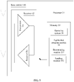
- FIG. 5 shows a hardware structure implementing an access network device 140, which is not part of the invention, but an illustrative example necessary for understanding the invention.
- the access network device 140 includes a processor 31, a transceiver 32, and a memory 33.
- the processor 31 includes one or more processing cores, and the processor 31 executes various function applications and information processing by running a software program and a module.
- the transceiver 32 includes a receiver Rx and a transmitter Tx.
- the transceiver 32 may be alternatively implemented as a communications chip.
- the communications chip may include a receiving module, a transmission module, a modem module, and the like, and is configured to modulate/demodulate information and receive/send the information by using a radio signal.
- the transceiver 32, the memory 33, and the processor 31 are coupled by using a bus.
- the memory 33 may be configured to store a software program and a module.
- the memory may store an operating system 34 and an application program module 35 required by at least one function.
- the application program module 35 includes at least a determining module 351 configured to determine information and a sending module 352 configured to send information.
- the determining module 351 is configured to determine minimum guaranteed power information of channels carried by a first carrier.
- the sending module 352 is configured to send, to a terminal, the minimum guaranteed power information of the channels carried by the first carrier.
- the minimum guaranteed power information is used to by the terminal to obtain, when a sum of any of the first initial transmit powers and a second initial transmit power is greater than a maximum transmit power of the terminal, an available transmit power for channels that are transmitted in N first subframes and that are carried by the first carrier and an available transmit power of a channel that is transmitted in a second subframe and that is carried by a second carrier, based on a priority order between channels that are transmitted in M first subframes and that are carried by the first carrier and the channel that is transmitted in the second subframe and that is carried by the second carrier and based on the minimum guaranteed power information of the channels carried by the first carrier.
- the first initial transmit power includes an initial transmit power of the channel that is transmitted in each of the M first subframes and that is carried by the first carrier.
- the second initial transmit power is an initial transmit power of the channel that is transmitted in the second subframe and that is carried by the second carrier.
- the second subframe on the second carrier overlaps the N first subframes on the first carrier.
- the M first subframes are first M first subframes of the N first subframes, N is greater than M, and M and N are positive integers.
- the processor 31 is configured to execute modules in the application program module 35, to implement steps in FIG. 6 that need to be performed by the access network device.
- the determining module 351 is configured to determine a power adjustment factor.
- the sending module 352 is configured to send the power adjustment factor to a terminal.
- the power adjustment factor is used by the terminal to obtain an available transmit power of a channel in a second part of a subframe based on the power adjustment factor and an available transmit power of a channel in a first part of the subframe.
- the subframe includes the first part and the second part, and the second part follows the first part.
- the power adjustment factor is used to determine an offset value between the available transmit power of the channel in the first part of the subframe and the available transmit power of the channel in the second part of the subframe.
- the processor 31 is configured to execute modules in the application program module 35, to implement steps in FIG. 7 that need to be performed by the access network device.
- the memory 33 is a computer readable storage medium, and may be implemented by any type of volatile or non-volatile storage device or a combination thereof, such as a static random access memory (SRAM), an electrically erasable programmable read-only memory (EEPROM), an erasable programmable read-only memory (EPROM), a programmable read-only memory (PROM), a read-only memory (ROM), a magnetic memory, a flash memory, a magnetic disk, or an optical disc.
- SRAM static random access memory
- EEPROM electrically erasable programmable read-only memory
- EPROM erasable programmable read-only memory
- PROM programmable read-only memory
- ROM read-only memory
- magnetic memory a magnetic memory
- flash memory a flash memory
- magnetic disk a magnetic disk, or an optical disc.
- a structure of the access network device 140 shown in FIG. 5 does not constitute any limitation on the access network device, and the access network device may include components more or fewer than those shown in the figure, a combination of some components, or components disposed differently.
- FIG. 6 shows a power allocation method according to an embodiment of the present invention. The method is implemented by using the system shown in FIG. 1 or FIG. 2 . The method includes the following steps.
- a terminal determines a first initial transmit power and a second initial transmit power, where the first initial transmit power includes an initial transmit power of a channel that is transmitted in each of M first subframes and that is carried by a first carrier, and the second initial transmit power is an initial transmit power of a channel that is transmitted in a second subframe and that is carried by a second carrier.
- the terminal Before power allocation, the terminal receives DCI (for example, the DCI 1 and the DCI 2 in FIG. 3 ).
- the DCI 1 carries information that is used to determine a channel transmit power of a long subframe i
- the DCI 2 carries only information that is used to determine a channel transmit power for first M short subframes of N short subframes that overlap the long subframe i.
- the terminal determines the first initial transmit power and the second initial transmit power based on the DCI.
- S101 An access network device determines minimum guaranteed power information of channels carried by the first carrier.
- the minimum guaranteed power information of the channels carried by the first carrier may be an index of a ratio of a minimum guaranteed power to a maximum transmit power.
- the minimum guaranteed power for the channels carried by the first carrier is greater than or equal to 0, and the ratio of the minimum guaranteed power to the maximum transmit power PCMAX may be in a percentage (in %) form.
- the ratio of the minimum guaranteed power for the channels carried by the first carrier to the maximum transmit power may be any one of the following listed candidate values: 0%, 5%, 10%, 15%, 20%, 30%, 37%, 44%, 50%, 56%, 63%, 70%, 80%, 90%, 95%, and 100%.
- the minimum guaranteed power for the channels carried by the first carrier is determined based on the index in the minimum guaranteed power information. For example, if the index is 6, the corresponding ratio of the minimum guaranteed power to the maximum transmit power is 30%, and the minimum guaranteed power can be obtained through calculation based on the maximum transmit power.
- the access network device may determine the minimum guaranteed power information of the channels carried by the first carrier, based on a type and a priority of to-be-transmitted data in several overlapping uplink short sub frames.
- the access network device may determine the minimum guaranteed power information of the channels carried by the first carrier, based on the type of the to-be-transmitted data in the several overlapping uplink short subframes. Specifically, when a channel of the to-be-transmitted data in the several overlapping uplink short subframes has a relatively high priority (for example, several data types with a highest priority), the ratio of the minimum guaranteed power for the channels carried by the first carrier and the maximum transmit power may by greater than or equal to a specified value (for example, 50%).
- a specified value for example, 50%
- the minimum guaranteed power of the channels carried by the first carrier may be any one of the foregoing candidate values greater than or equal to 50%.
- the minimum guaranteed power information of the channels carried by the first carrier in step S101 is used by the terminal, during a validity period, only when a power is allocated to uplink data on the first carrier in the several overlapping uplink subframes.
- the validity period may be a quantity of times (for example, one or several times) or may be time (for example, a period of time).
- the minimum guaranteed power information of the channels carried by the first carrier in step S101 may be used whenever the terminal allocates a power to the first carrier in the several overlapping uplink subframes.
- the access network device sends the minimum guaranteed power information of the channels carried by the first carrier to a terminal.
- S102 may include: sending, by the access network device, higher layer signaling or physical layer signaling to the terminal, where the higher layer signaling or the physical layer signaling includes the minimum guaranteed power information of the channels carried by the first carrier.
- the higher layer signaling may be radio resource control (Radio Resource Control, "RRC” for short) signaling
- RRC Radio Resource Control
- DCI DCI signaling
- S102 may include: sending, by the access network device on the first carrier or the second carrier, the minimum guaranteed power information of the channels carried by the first carrier.
- the higher layer signaling or the physical layer signaling may be higher layer signaling or physical layer signaling that is sent on the second carrier, or the higher layer signaling or the physical layer signaling may be higher layer signaling or physical layer signaling that is sent on the first carrier.
- the physical layer signaling is physical layer signaling sent on a primary component carrier (for example, the second carrier), or the physical layer signaling is physical layer signaling sent on a secondary component carrier (for example, the first carrier).
- the DCI signaling is DCI signaling sent on a primary component carrier, or the DCI signaling is DCI signaling sent on a secondary component carrier.
- the DCI signaling may be DCI signaling (different from DCI signaling used for a downlink grant (DL grant)) that is particularly used to transmit the minimum guaranteed power information.
- the access network device further sends, to the terminal by using indication signaling, power allocation information of channels that are in N first subframes and that are carried by the first carrier.
- the indication signaling is higher layer signaling or physical layer signaling that carries power allocation information of a channel that is in each of the N first subframes and that is carried by the first carrier.
- the indication signaling is the physical layer signaling
- a transmission subframe of first signaling that is sent on the first carrier overlaps a transmission subframe of second signaling that is sent on the second carrier.
- the second signaling carries the power allocation information of the channel that is carried by the second carrier in the second subframe.
- the DCI 2 carries the power allocation information of the channel that is carried by the first carrier in the N first sub frames.
- the access network device sends two pieces of DCI to the terminal.
- the two pieces of DCI are separately used to indicate power allocation information of channels that are carried by the first carrier in M first subframes and power allocation information of channels that are carried by the first carrier in (N-M) first subframes.
- S103 The terminal receives the minimum guaranteed power information that is of the channels carried by the first carrier and that is transmitted by the access network device.
- S103 may include: receiving, by the terminal, first signaling that is sent by the access network device on the first carrier or the second carrier, where the first signaling is higher layer signaling or physical layer signaling that carries the minimum guaranteed power information of the channels carried by the first carrier.
- the transmission subframe of the first signaling that is sent on the first carrier overlaps the transmission subframe of the second signaling that is sent on the second carrier, and the second signaling carries the power allocation information of the channel that is carried by the second carrier in the second subframe.
- FIG. 3 is used as an example.
- the second signaling may be the DCI 1
- the first signaling may be the DCI 2.
- Transmission subframes of the DCI 1 and DCI 2 overlap with each other.
- the minimum guaranteed power information, carried in the DCI 2, of the channels carried by the first carrier may be used in subsequent power allocation.
- the terminal receives the power allocation information of the channels that are in the N first subframes and that are carried by the first carrier, where the power allocation information is sent by the access network device by using the indication signaling.
- the terminal obtains an available transmit power for channels that are transmitted in N first subframes and that are carried by the first carrier and an available transmit power of a channel that is transmitted in a second subframe and that is carried by a second carrier, based on a priority order between channels that are transmitted in M first subframes and that are carried by the first carrier and the channel that is transmitted in the second subframe and that is carried by the second carrier and based on the minimum guaranteed power information of the channels carried by the first carrier.
- the second subframe on the second carrier overlaps the N first subframes on the first carrier, the M first subframes are first M first subframes of the N first subframe, N is greater than M, and M and N are positive integers.
- Both the first subframe and the second subframe are uplink subframes.
- the M first subframes have a same length but may transmit different channels.
- overlapping time between the second subframe on the second carrier and the N first subframes on the first carrier is greater than or equal to a preset threshold.
- the overlapping time is a time length of an overlapping part.
- the threshold may be time or a ratio of the overlapping time to a time length of the N first subframes. For example, the overlapping time is 50% of the time length of the N first subframes.
- one uplink subframe (the second subframe) on a low-frequency carrier (the second carrier) overlaps three uplink subframes (the first subframe) on a high-frequency carrier (the first carrier), (where for example, the low-frequency carrier may be 2GHz, and the high-frequency carrier is 28 GHz; alternatively, the low-frequency carrier and the high-frequency carrier may be other values, provided that a ratio of an uplink subframe length corresponding to the low-frequency carrier and an uplink subframe length corresponding to the high-frequency carrier is 1/3.)
- the terminal may obtain a transmit power for uplink data transmission in three uplink subframes on the high-frequency carrier and a transmit power for uplink data transmission in one uplink subframe on the low-frequency carrier based on the minimum guaranteed power information of the uplink data transmission on the high-frequency carrier and based on priorities of channels of first two uplink subframes on the high-frequency carrier and a channel of one uplink subframe on the low-frequency carrier
- S104 includes the following steps.
- the terminal obtains a minimum guaranteed power based on the minimum guaranteed power information of the channels carried by the first carrier.
- the minimum guaranteed power information in step S101 is an index of the minimum guaranteed power.
- the terminal stores candidate values for the ratio of the minimum guaranteed power to the maximum transmit power. After obtaining the index of the minimum guaranteed power, the terminal determines, from these candidate values based on the index, the ratio of the minimum guaranteed power to the maximum transmit power, and then can obtain the minimum guaranteed power through calculation based on the ratio and the maximum transmit power.
- the terminal obtains a first available transmit power for the channels that are transmitted in the N first subframes and that are carried by the first carrier and a second available transmit power of the channel that is transmitted in the second subframe and that is carried by the second carrier, based on the priority order between the channels that are transmitted in the M first subframes and that are carried by the first carrier and the channel that is transmitted in the second subframe and that is carried by the second carrier.
- step S1042 to determine the priority order between the channels that are transmitted in the M first subframes and that are carried by the first carrier and the channel that is transmitted in the second subframe and that is carried by the second carrier, the terminal first needs to obtain a priority order rule.
- the priority order rule is used to determine a priority order of channels of uplink subframes.
- the priority order rule may be predefined, and is pre-stored in a terminal, and the terminal can directly obtain the priority order rule when determining a priority.
- the priority order rule is sent by the access network device to the terminal.
- the process may specifically include the following steps.
- Step 1 The access network device sends the priority order rule to the terminal.
- the access network device may send the priority order rule to the terminal by using higher layer signaling or physical layer signaling.
- the higher layer signaling may be RRC signaling, and the physical layer signaling may be DCI signaling.
- the access network device may send the priority order rule to the terminal on the first carrier or the second carrier.
- the access network device sends the higher layer signaling or the physical layer signaling to the terminal on the first carrier or the second carrier.
- the higher layer signaling or the physical layer signaling includes the priority order rule.
- the priority order rule is used to determine the priority order between the channels that are transmitted in the M first subframes and that are carried by the first carrier and the channel that is transmitted in the second subframe and that is carried by the second carrier.
- priority order rules are different.
- the access network device may configure different priority order rules for different users according to different scenarios.
- the physical layer signaling is physical layer signaling sent on a primary component carrier (for example, the second carrier), or the physical layer signaling is physical layer signaling sent on a secondary component carrier (for example, the first carrier).
- the DCI signaling is DCI signaling sent on a primary component carrier, or the DCI signaling is DCI signaling sent on a secondary component carrier.
- a channel priority order includes at least one of the following: a priority order between channel types, a priority order between uplink control information (Uplink Control Information, "UCI" for short) carried by channels, and a priority order between carriers corresponding to channels.
- UCI Uplink Control Information
- the priority order between channel types includes at least one of the following:
- the priority order between UCI carried by channels includes at least one of the following:
- the priority order between carriers corresponding to channels includes at least one of the following: a priority order determined based on index numbers of carriers, a priority order of carriers that is configured at a higher layer, a priority order determined based on a duplex manner of carriers, a priority order determined based on radio resource control RRC connection states of carriers, and a priority order determined based on transmission points corresponding to carriers.
- the priority order may be correspondingly set according to an actual scenario.
- a primary component carrier is used to transmit a RACH
- a secondary component carrier is used to transmit an acknowledgment (Acknowledgment, "ACK" for short) instruction (carried on a PUSCH).
- ACK acknowledgment
- the priority order between channel types is: PRACH > PUSCH.
- the priority order between channel types may be: PRACH > PUCCH > PUSCH with UCI > PUSCH without UCI > SRS.
- the random access channel has a highest priority
- the uplink control channel has a second highest priority
- the uplink shared channel transmitting UCI has a third highest priority
- the uplink shared channel transmitting no UCI has a fourth highest priority
- the sounding reference signal has a lowest priority.
- the scenario is related to multi-beam sweeping.
- the terminal sends a plurality of random access channels (Random Access Channel, "RACH" for short) by using a plurality of beams in a time division manner.
- RACH Random Access Channel
- 10 RACHs are used as an example.
- a priority of the RACH may be lower than a priority of the PUCCH, that is, PUCCH > PRACH.
- a priority order between carriers or cell groups corresponding to channels may be that a priority of any uplink channel on a primary component carrier or in a master cell group is greater than or equal to a priority of any uplink channel on a secondary component carrier or in a secondary cell group.
- the step may include the following steps:
- the access network device determines a corresponding priority order rule based on a type of a data channel that is to be scheduled immediately, and the access network device sends the corresponding priority order rule to the terminal.
- Step 2 The terminal receives the priority order rule sent by the access network device.
- the terminal receives the higher layer signaling or the physical layer signaling that is sent by the access network device on the first carrier or the second carrier.
- the higher layer signaling or the physical layer signaling includes the priority order rule.
- the priority order rule is used to determine the priority order between the channels that are transmitted in the M first subframes and that are carried by the first carrier and the channel that is transmitted in the second subframe and that is carried by the second carrier.
- Step 3 The terminal determines, according to the priority order rule, the priority order between the channels that are transmitted in the M first subframes and that are carried by the first carrier and the channel that is transmitted in the second subframe and that is carried by the second carrier.
- the terminal first selects a first subframe from the M first subframes on the first carrier according to the priority order rule, and then compares a priority of the channel transmitted in the first subframe and a priority of the channel transmitted in the second subframe.
- the selecting a first subframe from the M first subframes on the first carrier specifically includes: selecting a first subframe with a highest channel priority from the M first subframes; or selecting a first subframe with a lowest channel priority from the M first subframes; or selecting a first subframe with a specified channel priority (for example, a second highest priority) from the M first subframes.
- the priority order rule includes only one of the foregoing priority orders, for example, includes only the priority order between channel types, if channels of two uplink subframes are of a same type, priorities are the same.
- the priority order rule includes more than two of the foregoing priority orders, for example, includes the priority order between channel types and the priority order between UCI carried by channels, if channels of two uplink subframes are of a same type, for example, if both channels carry uplink control information, priorities of UCI carried by the channels are compared.
- the obtaining a first available transmit power for the channels that are transmitted in the N first subframes and that are carried by the first carrier and a second available transmit power of the channel that is transmitted in the second subframe and that is carried by the second carrier, based on a priority order between the channels that are transmitted in the M first subframes and that are carried by the first carrier and the channel that is transmitted in the second subframe and that is carried by the second carrier includes: reducing the first initial transmit power and the second initial transmit power based on the priority order, to respectively obtain the first available transmit power for the channels that are transmitted in the N first subframes and that are carried by the first carrier and the second available transmit power of the channel that is transmitted in the second subframe and that is carried by the second carrier, where a sum of the first available transmit power for the channels that are transmitted in the N first subframes and that are carried by the first carrier and the second available transmit power of the channel that is transmitted in the second subframe and that is carried by the second carrier is less than or
- an initial transmit power of a channel with a lower priority is reduced until the sum of the first available transmit power for the channels that are transmitted in the N first subframes and that are carried by the first carrier and the second available transmit power of the channel that is transmitted in the second subframe and that is carried by the second carrier is less than or equal to the maximum transmit power.
- initial transmit powers of channels with different priorities are reduced according to different reduction ratios (a reduction ratio of a channel with a lower priority is greater than a reduction ratio of a channel with a higher priority) until the sum of the first available transmit power for the channels that are transmitted in the N first subframes and that are carried by the first carrier and the second available transmit power of the channel that is transmitted in the second subframe and that is carried by the second carrier is less than or equal to the maximum transmit power.
- the terminal determines, based on the minimum guaranteed power and at least one of the first available transmit power and the second available transmit power, at least one of the available transmit power for the channels that are transmitted in the N first subframes and that are carried by the first carrier and the available transmit power of the channel that is transmitted in the second subframe and that is carried by the second carrier.
- the terminal may determine the available transmit power for the channels that are transmitted in the N first subframes and that are carried by the first carrier in the following manner: Maximum ⁇ P_priority, P_guaranteed ⁇ , where P_priority is the first available transmit power for the channels that are transmitted in the N first subframes and that is carried by the first carrier, and P_guaranteed is the minimum guaranteed power.
- an available transmit power of a channel that is transmitted in the second subframe and that is carried by the second carrier may be the second available transmit power.
- the available transmit power for the channels that are transmitted in the N first subframe and that are carried by the first carrier may be determined by taking a minimum value or an average value. This is not limited herein.
- the sum of the finally obtained available transmit power for the channels that are transmitted in the N first subframes and that are carried by the first carrier and the finally obtained available transmit power of the channel that is transmitted in the second subframe and that is carried by the second carrier is less than or equal to the maximum transmit power.
- the method may further include: transmitting, by the terminal based on the available transmit power for the channels that are transmitted in the N first subframes and that are carried by the first carrier, the channels that are transmitted in the N first subframes and that are carried by the first carrier, and transmitting, based on the available transmit power of the channel that is transmitted in the second subframe and that is carried by the second carrier, the channel that is transmitted in the second subframe and that is carried by the second carrier.
- the method may further include: transmitting, by the terminal based on the available transmit power for the channels that are transmitted in the N first subframes and that are carried by the first carrier, the channels that are transmitted in the N first subframes and that are carried by the first carrier, and transmitting, based on the second available transmit power of the channel that is transmitted in the second subframe and that is carried by the second carrier, the channel that is transmitted in the second subframe and that is carried by the second carrier.
- the method may further include: transmitting, by the terminal based on the first available transmit power for the channels that are transmitted in the N first subframes and that are carried by the first carrier, the channels that are transmitted in the N first subframes and that are carried by the first carrier, and transmitting, based on the available transmit power of the channel that is transmitted in the second subframe and that is carried by the second carrier, the channel that is transmitted in the second subframe and that is carried by the second carri er.
- an uplink subframe on one carrier or in one cell group overlaps a plurality of uplink subframes on another carrier or in another cell group, a minimum guaranteed power is reserved for a last part in an overlapping area, so that a power requirement in the last part of the overlapping area can be met during uplink power allocation to the two carriers, to ensure performance of data transmission in an uplink subframe of the last part in the overlapping area.
- This implements maximization of power efficiency of uplink data transmission and data transmission performance.
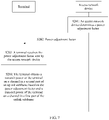
- FIG. 7 shows a power adjustment method, which is not part of the invention, but an illustrative example necessary for understanding the invention.
- the method is implemented by using the system shown in FIG. 1 or FIG. 2 .
- the method includes the following steps.
- An access network device determines a power adjustment factor.
- the power adjustment factor is used to determine an offset value between an available transmit power of a channel in a first part of a subframe and an available transmit power of a channel in a second part of the subframe.
- the power adjustment factor is specifically configured to: when a terminal sends data in an uplink subframe, adjust a transmit power of the data in the uplink subframe. Specifically, the terminal sends uplink data in the first part of the uplink subframe by using a first power, then obtains a second power through calculation based on the offset value and the first power, and sends uplink data in the second part of the uplink subframe by using the second power.
- the offset value may be a ratio value or a difference value.
- the power adjustment factor is a difference value, controlling the offset value to be positive or negative to increase or reduce the first power, to obtain the second power.
- the power adjustment factor is a ratio value, controlling the power value to be greater than or less than 1 to increase or reduce the first power, to obtain the second power.
- the power adjustment factor is a cell-specific parameter.
- the power adjustment factor is set based on a cell, and therefore the power adjustment factor is the cell-specific parameter.
- step S201 may include the following steps: The access network device determines a cell in which the terminal is located, and the access network device determines a corresponding power adjustment factor based on the cell in which the terminal is located.
- the access network device sends the power adjustment factor to a terminal.
- S202 may include: sending, by the access network device, the power adjustment factor to the terminal by using higher layer signaling or physical layer signaling.
- the higher layer signaling may be RRC signaling, and the physical layer signaling may be DCI signaling.
- the physical layer signaling is physical layer signaling transmitted on a primary component carrier (for example, the second carrier), or the physical layer signaling is physical layer signaling transmitted on a secondary component carrier (for example, the first carrier).
- the DCI signaling is DCI signaling transmitted on a primary component carrier, or the DCI signaling is DCI signaling transmitted on a secondary component carrier.
- S203 The terminal receives the power adjustment factor sent by the access network device.
- S203 may include: receiving, by the terminal, the power adjustment factor that is sent by the access network device by using the higher layer signaling or the physical layer signaling.
- the terminal obtains a transmit power of the terminal on a channel in a second part of an uplink subframe based on the power adjustment factor and a transmit power of the terminal on a channel in a first part of the uplink subframe, where the uplink subframe includes the first part and the second part, and the second part follows the first part.
- the terminal After determining the transmit powers of the two parts based on the power adjustment factor, the terminal sends the uplink subframe by using the two determined transmit powers.
- Two parts of an uplink subframe may be obtained through division by symbol or timeslot, and this is not limited herein.
- the transmit powers of the channels in the two parts of the uplink subframe are adjusted by using the power adjustment factor, so that the transmit powers of the channels in the two parts of the uplink subframe can be adjusted in real time, and power allocation and power efficiency of the channels in the two parts of the uplink subframe can be maximized.
- FIG. 8 is a block diagram of a communications apparatus according to an embodiment of this application.
- the communications apparatus may be implemented as all or a part of a terminal by using a dedicated hardware circuit or a combination of software and hardware.
- the communications apparatus includes a determining unit 801, a receiving unit 802, and a processing unit 803.
- the determining unit 801 is configured to determine a first initial transmit power and a second initial transmit power.
- the first initial transmit power includes an initial transmit power of a channel that is transmitted in each of M first subframes and that is carried by a first carrier.
- the second initial transmit power is an initial transmit power of a channel that is transmitted in a second subframe and that is carried by a second carrier.
- the receiving unit 802 is configured to receive minimum guaranteed power information that is of channels carried by the first carrier and that is sent by an access network device.
- the processing unit 803 is configured to: when a sum of any of the first initial transmit powers and the second initial transmit power is greater than a maximum transmit power of the terminal, obtain an available transmit power for channels that are transmitted in N first subframes and that are carried by the first carrier and an available transmit power of the channel that is transmitted in the second subframe and that is carried by the second carrier, based on a priority order between the channels that are transmitted in the M first subframes and that are carried by the first carrier and the channel that is transmitted in the second subframe and that is carried by the second carrier and based on the minimum guaranteed power information of the channels carried by the first carrier.
- the second subframe on the second carrier overlaps the N first subframes on the first carrier, the M first subframes are first M first subframes of the N first subframes, N is greater than M, and M and N are positive integers.
- the processing unit 803 is configured to:
- the processing unit 803 is configured to: reduce the first initial transmit power and the second initial transmit power based on the priority order, to respectively obtain the first available transmit power for the channels that are transmitted in the N first subframes and that are carried by the first carrier and the second available transmit power of the channel that is transmitted in the second subframe and that is carried by the second carrier, where a sum of the first available transmit power for the channels that are transmitted in the N first subframes and that are carried by the first carrier and the second available transmit power of the channel that is transmitted in the second subframe and that is carried by the second carrier is less than or equal to the maximum transmit power.
- the priority order between the channels that are transmitted in the M first subframes and that are carried by the first carrier and the channel that is transmitted in the second subframe and that is carried by the second carrier includes at least one of a priority order between channel types, a priority order between UCI carried by channels, and a priority order between carriers corresponding to channels.
- the receiving unit 802 is further configured to: receive higher layer signaling or physical layer signaling that is sent by the access network device on the first carrier or the second carrier, where the higher layer signaling or the physical layer signaling includes a priority order rule, and the priority order rule is used to determine the priority order between the channels that are transmitted in the M first subframes and that are carried by the first carrier and the channel that is transmitted in the second subframe and that is carried by the second carrier.
- the receiving unit 802 is configured to: receive first signaling that is sent by the access network device on the first carrier or the second carrier, where the first signaling is higher layer signaling or physical layer signaling that carries the minimum guaranteed power information of the channels carried by the first carrier.
- the receiving unit 802 may be implemented by a receiver or a processor coordinating with a receiver.
- the determining unit 801 and the processing unit 803 each may be implemented by a processor or by a processor executing a program instruction in a memory.
- FIG. 9 is a block diagram of a communications apparatus, which is not part of the invention, but an illustrative example necessary for understanding the invention.
- the communications apparatus may be implemented as all or a part of an access network device by using a dedicated hardware circuit or a combination of software and hardware.
- the communications apparatus includes a determining unit 901 and a sending unit 902.
- the determining unit 901 is configured to determine minimum guaranteed power information of channels carried by a first carrier.
- the sending unit 902 is configured to send, to a terminal, the minimum guaranteed power information of the channels carried by the first carrier.
- the sending unit 902 is configured to: send higher layer signaling or physical layer signaling to the terminal on the first carrier or the second carrier, where the higher layer signaling or the physical layer signaling includes the minimum guaranteed power information of the channels carried by the first carrier.
- the sending unit 902 is further configured to: send the higher layer signaling or the physical layer signaling to the terminal on the first carrier or the second carrier, where the higher layer signaling or the physical layer signaling includes a priority order rule, and the priority order rule is used to determine the priority order between the channels that are transmitted in the M first subframes and that are carried by the first carrier and the channel that is transmitted in the second subframe and that is carried by the second carrier.
- the higher layer signaling or the physical layer signaling includes a priority order rule
- the priority order rule is used to determine the priority order between the channels that are transmitted in the M first subframes and that are carried by the first carrier and the channel that is transmitted in the second subframe and that is carried by the second carrier.
- the priority order between the channels that are transmitted in the M first subframes and that are carried by the first carrier and the channel that is transmitted in the second subframe and that is carried by the second carrier includes at least one of a priority order between channel types, a priority order between UCI carried by channels, and a priority order between carriers corresponding to channels.
- the determining unit 901 may be implemented by a processor or by a processor executing a program instruction in a memory.
- the sending unit 902 may be implemented by a transmitter or by a processor coordinating with a transmitter.
- FIG. 10 is a block diagram of a communications apparatus, which is not part of the invention, but an illustrative example necessary for understanding the invention.
- the communications apparatus may be implemented as all or a part of a terminal by using a dedicated hardware circuit or a combination of software and hardware.
- the communications apparatus includes a receiving unit 1001 and a processing unit 1002.
- the receiving unit 1001 is configured to receive a power adjustment factor sent by an access network device.
- the processing unit 1002 is configured to obtain an available transmit power of a channel in a second part of a subframe based on the power adjustment factor and an available transmit power of a channel in a first part of the subframe.
- the subframe includes the first part and the second part, and the second part follows the first part.
- the power adjustment factor is used to determine an offset value between the available transmit power of the channel in the first part of the subframe and the available transmit power of the channel in the second part of the subframe.
- the receiving unit 1001 is configured to: receive the power adjustment factor that is sent by the access network device by using higher layer signaling or physical layer signaling.
- the power adjustment factor is a cell-specific parameter.
- the receiving unit 1001 may be implemented by a receiver or a processor coordinating with a receiver.
- the processing unit 1002 may be implemented by a processor or by a processor executing a program instruction in a memory.
- FIG. 11 is a block diagram of a communications apparatus, which is not part of the invention, but an illustrative example necessary for understanding the invention.
- the communications apparatus may be implemented as all or a part of an access network device by using a dedicated hardware circuit or a combination of software and hardware.
- the communications apparatus includes a determining unit 1101 and a sending unit 1102.
- the determining unit 1101 is configured to determine a power adjustment factor.
- the sending unit 1102 is configured to send the power adjustment factor to a terminal, where the power adjustment factor is used by the terminal to obtain an available transmit power of a channel in a second part of a subframe based on the power adjustment factor and an available transmit power of a channel in a first part of the subframe.
- the subframe includes the first part and the second part, and the second part follows the first part.
- the power adjustment factor is used to determine an offset value between the available transmit power of the channel in the first part of the subframe and the available transmit power of the channel in the second part of the subframe.
- the sending unit 1102 is configured to: send the power adjustment factor to the terminal by using higher layer signaling or physical layer signaling.
- the power adjustment factor is a cell-specific parameter.
- the determining unit 1101 may be implemented by a processor or by a processor executing a program instruction in a memory.
- the sending unit 1102 may be implemented by a transmitter or by a processor coordinating with a transmitter.
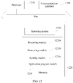
- FIG. 12 is a structural diagram of a communications chip, which is not part of the invention, but an illustrative example necessary for understanding the invention.
- the communications chip is applied to a mobile communications system device such as the foregoing access network device or terminal.
- the communications chip includes a processor 1210, a memory 1220, and a communications interface 1230.
- the processor 1210 is connected to both the memory 1220 and the communications interface 1230 by using a bus.
- the communications interface 1230 is configured to implement communication with another communications device.
- the processor 1210 includes one or more processing cores.
- the processor 1210 runs an operating system or an application program module.
- the memory 1220 may store an operating system 1222 and an application program module 1224 required by at least one function.
- the application program module 1224 includes a receiving module 1224a, a processing module 1224b, and a sending module 1224c.
- the receiving module 1224a is configured to implement a receiving-related step.
- the processing module 1224b is configured to implement a calculation-related or processing-related step.
- the sending module 1224c is configured to implement a sending-related step.
- the memory 1220 may be implemented by any type of volatile or non-volatile storage device or a combination thereof, such as a static random access memory (SRAM), an electrically erasable programmable read-only memory (EEPROM), an erasable programmable read-only memory (EPROM), a programmable read-only memory (PROM), a read-only memory (ROM), a magnetic memory, a flash memory, a magnetic disk, or an optical disc.
- SRAM static random access memory
- EEPROM electrically erasable programmable read-only memory
- EPROM erasable programmable read-only memory
- PROM programmable read-only memory
- ROM read-only memory
- magnetic memory a magnetic memory
- flash memory a flash memory
- magnetic disk a magnetic disk
- optical disc an optical disc
- FIG. 12 does not constitute any limitation on the communications chip, and the communications chip may include components more or fewer than those shown in the figure, a combination of some components, or components disposed differently.
- the program may be stored in a computer-readable storage medium.
- the storage medium may include a read-only memory, a magnetic disk, or an optical disc.
Landscapes
- Engineering & Computer Science (AREA)
- Signal Processing (AREA)
- Computer Networks & Wireless Communication (AREA)
- Power Engineering (AREA)
- Mobile Radio Communication Systems (AREA)
Claims (10)
- Procédé d'attribution de puissance, dans lequel le procédé comprend :la détermination (S100), par un terminal, d'une première puissance d'émission initiale et d'une seconde puissance d'émission initiale, dans lequel la première puissance d'émission initiale comprend une puissance d'émission initiale d'un canal qui est transmis dans chacune des M premières sous-trames et qui est porté par une première porteuse, et la seconde puissance d'émission initiale est une puissance d'émission initiale d'un canal qui est transmis dans une seconde sous-trame et qui est porté par une seconde porteuse ;la réception (S103), par le terminal, d'informations de puissance minimale garantie qui sont des informations de canaux portés par la première porteuse et qui sont envoyées par un dispositif de réseau d'accès ; etlorsqu'une somme de l'une quelconque des premières puissances d'émission initiales et de la seconde puissance d'émission initiale est supérieure à une puissance d'émission maximale du terminal, l'obtention, par le terminal, d'une puissance d'émission disponible pour les canaux qui sont transmis dans N premières sous-trames et qui sont portés par la première porteuse et d'une puissance d'émission disponible du canal qui est transmis dans la seconde sous-trame et qui est porté par la seconde porteuse, sur la base d'un ordre de priorité entre les canaux qui sont transmis dans les M premières sous-trames et qui sont portés par la première porteuse et le canal qui est transmis dans la seconde sous-trame et qui est porté par la seconde porteuse et sur la base des informations de puissance minimale garantie des canaux portés par la première porteuse, dans lequel la seconde sous-trame sur la seconde porteuse chevauche les N premières sous-trames sur la première porteuse, les M premières sous-trames sont les M premières sous-trames des N premières sous-trames, N est supérieur à M, et M et N sont des entiers positifs, dans lequel la seconde sous-trame sur la seconde porteuse est plus grande que l'une quelconque des N premières sous-trames sur la première porteuse,dans lequel l'obtention, par le terminal, d'une puissance d'émission disponible pour les canaux qui sont transmis dans N premières sous-trames et qui sont portés par la première porteuse et une puissance d'émission disponible du canal qui est transmis dans la seconde sous-trame et qui est porté par la seconde porteuse, sur la base d'un ordre de priorité entre les canaux qui sont transmis dans les M premières sous-trames et qui sont portés par la première porteuse et le canal qui est transmis dans la seconde sous-trame et qui est porté par la seconde porteuse et sur la base des informations de puissance minimale garantie des canaux portés par la première porteuse comprend :
l'obtention (S1041), par le terminal, d'une puissance minimale garantie sur la base des informations de puissance minimale garantie des canaux portés par la première porteuse, dans lequel les informations de puissance minimale garantie sont un indice de la puissance minimale garantie ; dans lequel l'obtention de la puissance minimale garantie comprend les étapes :de stockage de valeurs candidates pour le rapport entre la puissance minimale garantie et la puissance d'émission maximale ;de détermination, par le terminal, à partir de ces valeurs candidates sur la base de l'indice, du rapport entre la puissance minimale garantie et la puissance d'émission maximale, etd'obtention, par le terminal, de la puissance minimale garantie par un calcul basé sur le rapport et la puissance d'émission maximale ;d'obtention (S1042), par le terminal, d'une première puissance d'émission disponible pour les canaux qui sont transmis dans les N premières sous-trames et qui sont portés par la première porteuse et une seconde puissance d'émission disponible du canal qui est transmis dans la seconde sous-trame et qui est porté par la seconde porteuse, sur la base de l'ordre de priorité entre les canaux qui sont transmis dans les M premières sous-trames et qui sont portés par la première porteuse et le canal qui est transmis dans la seconde sous-trame et qui est porté par la seconde porteuse ; etde détermination (S1043), par le terminal sur la base de la puissance minimale garantie et d'au moins l'une de la première puissance d'émission disponible ou de la seconde puissance d'émission disponible, d'au moins l'une de la puissance d'émission disponible pour les canaux qui sont transmis dans les N premières sous-trames et qui sont portés par la première porteuse et de la puissance d'émission disponible du canal qui est transmis dans la seconde sous-trame et qui est porté par la seconde porteuse. - Procédé selon la revendication 1, dans lequel l'obtention, par le terminal, d'une première puissance d'émission disponible pour les canaux qui sont transmis dans les N premières sous-trames et qui sont portés par la première porteuse et une seconde puissance d'émission disponible du canal qui est transmis dans la seconde sous-trame et qui est porté par la seconde porteuse, sur la base de l'ordre de priorité entre les canaux qui sont transmis dans les M premières sous-trames et qui sont portés par la première porteuse et le canal qui est transmis dans la seconde sous-trame et qui est porté par la seconde porteuse comprend :
la réduction de la première puissance d'émission initiale et de la seconde puissance d'émission initiale sur la base de l'ordre de priorité, pour obtenir respectivement la première puissance d'émission disponible pour les canaux qui sont transmis dans les N premières sous-trames et qui sont portés par la première porteuse et la seconde puissance d'émission disponible du canal qui est transmis dans la seconde sous-trame et qui est porté par la seconde porteuse, dans lequel une somme de la première puissance d'émission disponible du canal qui est transmis dans chacune des N premières sous-trames et qui est porté par la première porteuse et de la seconde puissance d'émission disponible du canal qui est transmis dans la seconde sous-trame et qui est porté par la seconde porteuse est inférieure ou égale à la puissance d'émission maximale. - Procédé selon l'une quelconque des revendications 1 et 2, dans lequel l'ordre de priorité entre les canaux qui sont transmis dans les M premières sous-trames et qui sont portés par la première porteuse et le canal qui est transmis dans la seconde sous-trame et qui est porté par la seconde porteuse comprend au moins l'un d'un ordre de priorité entre des types de canaux, d'un ordre de priorité entre des informations de commande de liaison montante, UCI, portées par des canaux, ou d'un ordre de priorité entre des porteuses correspondant à des canaux.
- Procédé selon la revendication 3, dans lequel l'ordre de priorité entre des types de canaux comprend au moins l'un des éléments suivants :lorsqu'il existe un canal d'accès aléatoire physique, PRACH, le PRACH a la priorité la plus élevée ;lorsqu'un canal de commande de liaison montante physique, PUCCH, et un canal partagé de liaison montante physique, PUSCH, coexistent, la priorité du PUCCH est supérieure à la priorité du PUSCH, ou la priorité du PUCCH est supérieure à la priorité d'un PUSCH ne portant pas d'UCI et est la même qu'une priorité d'un PUSCH portant des UCI ;lorsqu'un PUSCH portant des UCI et un PUSCH ne portant pas d'UCI coexistent, la priorité du PUSCH portant des UCI est supérieure à la priorité du PUSCH ne portant pas d'UCI ; oulorsqu'un PRACH, un PUCCH, un PUSCH et un signal de référence de sondage, SRS, coexistent, le SRS a la priorité la plus basse.
- Terminal, dans lequel le terminal comprend :une unité de détermination (801) configurée pour déterminer une première puissance d'émission initiale et une seconde puissance d'émission initiale, dans lequel la première puissance d'émission initiale comprend une puissance d'émission initiale d'un canal qui est transmis dans chacune des M premières sous-trames et qui est porté par une première porteuse, et la seconde puissance d'émission initiale est une puissance d'émission initiale d'un canal qui est transmis dans une seconde sous-trame et qui est porté par une seconde porteuse ;une unité de réception (802), configurée pour recevoir des informations de puissance minimale garantie qui sont des informations de canaux portés par la première porteuse et qui sont envoyées par un dispositif de réseau d'accès ; etune unité de traitement (803), configurée pour : lorsqu'une somme de l'une quelconque des premières puissances d'émission initiales et de la seconde puissance d'émission initiale est supérieure à une puissance d'émission maximale du terminal, obtenir une puissance d'émission disponible pour les canaux qui sont transmis dans N premières sous-trames et qui sont portés par la première porteuse et d'une puissance d'émission disponible du canal qui est transmis dans la seconde sous-trame et qui est porté par la seconde porteuse, sur la base d'un ordre de priorité entre les canaux qui sont transmis dans les M premières sous-trames et qui sont portés par la première porteuse et le canal qui est transmis dans la seconde sous-trame et qui est porté par la seconde porteuse et sur la base des informations de puissance minimale garantie des canaux portés par la première porteuse, dans lequel la seconde sous-trame sur la seconde porteuse chevauche les N premières sous-trames sur la première porteuse, les M premières sous-trames sont les M premières sous-trames des N premières sous-trames, N est supérieur à M, et M et N sont des entiers positifs, et dans lequel la seconde sous-trame sur la seconde porteuse est plus grande que l'une quelconque des N premières sous-trames sur la première porteuse,dans lequel l'unité de traitement est configurée pour :
obtenir une puissance minimale garantie sur la base des informations de puissance minimale garantie des canaux portés par la première porteuse, dans lequel les informations de puissance minimale garantie sont un indice de la puissance minimale garantie ; dans lequel pour obtenir la puissance minimale garantie, l'unité de traitement est configurée pour :stocker des valeurs candidates pour le rapport entre la puissance minimale garantie et la puissance d'émission maximale ;déterminer à partir de ces valeurs candidates sur la base de l'indice, le rapport entre la puissance minimale garantie et la puissance d'émission maximale, etobtenir la puissance minimale garantie par un calcul basé sur le rapport et la puissance d'émission maximale ;obtenir une première puissance d'émission disponible pour les canaux qui sont transmis dans les N premières sous-trames et qui sont portés par la première porteuse et une seconde puissance d'émission disponible du canal qui est transmis dans la seconde sous-trame et qui est porté par la seconde porteuse, sur la base de l'ordre de priorité entre les canaux qui sont transmis dans les M premières sous-trames et qui sont portés par la première porteuse et le canal qui est transmis dans la seconde sous-trame et qui est porté par la seconde porteuse ; etdéterminer, sur la base de la puissance minimale garantie et d'au moins l'une de la première puissance d'émission disponible ou de la seconde puissance d'émission disponible, au moins l'une de la puissance d'émission disponible pour les canaux qui sont transmis dans les N premières sous-trames et qui sont portés par la première porteuse et de la puissance d'émission disponible du canal qui est transmis dans la seconde sous-trame et qui est porté par la seconde porteuse. - Terminal selon la revendication 5, dans lequel l'unité de traitement est configurée pour :
réduire la première puissance d'émission initiale et la seconde puissance d'émission initiale sur la base de l'ordre de priorité, pour obtenir respectivement la première puissance d'émission disponible pour les canaux qui sont transmis dans les N premières sous-trames et qui sont portés par la première porteuse et la seconde puissance d'émission disponible du canal qui est transmis dans la seconde sous-trame et qui est porté par la seconde porteuse, dans lequel une somme de la première puissance d'émission disponible du canal qui est transmis dans chacune des N premières sous-trames et qui est porté par la première porteuse et de la seconde puissance d'émission disponible du canal qui est transmis dans la seconde sous-trame et qui est porté par la seconde porteuse est inférieure ou égale à la puissance d'émission maximale. - Terminal selon l'une quelconque des revendications 5 et 6, dans lequel l'ordre de priorité entre les canaux qui sont transmis dans les M premières sous-trames et qui sont portés par la première porteuse et le canal qui est transmis dans la seconde sous-trame et qui est porté par la seconde porteuse comprend au moins l'un d'un ordre de priorité entre des types de canaux, d'un ordre de priorité entre des informations de commande de liaison montante, UCI, portées par des canaux, ou d'un ordre de priorité entre des porteuses correspondant à des canaux.
- Terminal selon la revendication 7, dans lequel l'ordre de priorité entre des types de canaux comprend au moins l'un des éléments suivants :lorsqu'il existe un canal d'accès aléatoire physique, PRACH, le PRACH a la priorité la plus élevée ;lorsqu'un canal de commande de liaison montante physique, PUCCH, et un canal partagé de liaison montante physique, PUSCH, coexistent, la priorité du PUCCH est supérieure à la priorité du PUSCH, ou la priorité du PUCCH est supérieure à la priorité d'un PUSCH ne portant pas d'UCI et est la même qu'une priorité d'un PUSCH portant des UCI ;lorsqu'un PUSCH portant des UCI et un PUSCH ne portant pas d'UCI coexistent, la priorité du PUSCH portant des UCI est supérieure à la priorité du PUSCH ne portant pas d'UCI ; oulorsqu'un PRACH, un PUCCH, un PUSCH et un SRS coexistent, le SRS a la priorité la plus basse.
- Produit de programme informatique comprenant des instructions pour amener le terminal selon la revendication 5 à exécuter les étapes du procédé selon la revendication 1.
- Support de stockage lisible par ordinateur sur lequel est stocké le programme informatique selon la revendication 9.
Applications Claiming Priority (2)
| Application Number | Priority Date | Filing Date | Title |
|---|---|---|---|
| CN201610956516.2A CN108024323B (zh) | 2016-11-03 | 2016-11-03 | 功率分配方法、功率调整方法、终端和接入网设备 |
| PCT/CN2017/109238 WO2018082635A1 (fr) | 2016-11-03 | 2017-11-03 | Procédé d'attribution de puissance, procédé de réglage de puissance, terminal et dispositif de réseau d'accès |
Publications (3)
| Publication Number | Publication Date |
|---|---|
| EP3528558A1 EP3528558A1 (fr) | 2019-08-21 |
| EP3528558A4 EP3528558A4 (fr) | 2019-10-16 |
| EP3528558B1 true EP3528558B1 (fr) | 2022-05-11 |
Family
ID=62076663
Family Applications (1)
| Application Number | Title | Priority Date | Filing Date |
|---|---|---|---|
| EP17867719.1A Active EP3528558B1 (fr) | 2016-11-03 | 2017-11-03 | Procédé d'attribution de puissance, procédé de réglage de puissance, terminal et dispositif de réseau d'accès |
Country Status (6)
| Country | Link |
|---|---|
| US (1) | US11006375B2 (fr) |
| EP (1) | EP3528558B1 (fr) |
| JP (1) | JP2019536351A (fr) |
| CN (1) | CN108024323B (fr) |
| BR (1) | BR112019008993A2 (fr) |
| WO (1) | WO2018082635A1 (fr) |
Families Citing this family (11)
| Publication number | Priority date | Publication date | Assignee | Title |
|---|---|---|---|---|
| WO2020087437A1 (fr) * | 2018-11-01 | 2020-05-07 | Guangdong Oppo Mobile Telecommunications Corp., Ltd. | Équipement utilisateur et son procédé de communication sans fil |
| WO2020087454A1 (fr) * | 2018-11-01 | 2020-05-07 | Oppo广东移动通信有限公司 | Procédé de régulation de puissance et dispositif terminal |
| US11356962B2 (en) * | 2019-01-07 | 2022-06-07 | Qualcomm Incorporated | Power control in NR-NR dual connectivity |
| CN111565454A (zh) * | 2019-02-14 | 2020-08-21 | 索尼公司 | 电子装置、无线通信方法和计算机可读介质 |
| CN111586819B (zh) * | 2019-02-15 | 2023-10-20 | 华为技术有限公司 | 一种上行保证功率信息发送、接收方法及设备 |
| CN111615184B (zh) * | 2019-04-22 | 2023-12-22 | 维沃移动通信有限公司 | 处理方法及终端 |
| CN112399545B (zh) * | 2019-08-16 | 2024-04-12 | 华为技术有限公司 | 一种信号发送方法及装置 |
| CN116235568A (zh) * | 2020-08-06 | 2023-06-06 | 华为技术有限公司 | 用于多点通信中的上行定时的系统和方法 |
| CN113784427B (zh) * | 2021-08-18 | 2023-06-06 | 中国联合网络通信集团有限公司 | 功率控制方法及装置 |
| CN116017659A (zh) * | 2021-10-22 | 2023-04-25 | 华为技术有限公司 | 一种功率分配方法、装置及系统 |
| WO2024197766A1 (fr) * | 2023-03-31 | 2024-10-03 | Qualcomm Incorporated | Priorisation de puissance comprenant des cellules candidates |
Family Cites Families (15)
| Publication number | Priority date | Publication date | Assignee | Title |
|---|---|---|---|---|
| CN1161908C (zh) | 2001-07-20 | 2004-08-11 | 华为技术有限公司 | 带功率偏置的物理公共分组信道传输方法 |
| US8472967B2 (en) | 2008-02-01 | 2013-06-25 | Qualcomm Incorporated | Allocating transmit power among two or more carriers assigned to a wireless communication device |
| TWI508590B (zh) * | 2009-02-09 | 2015-11-11 | Interdigital Patent Holdings | 利用多載波無線傳送器/接收器單元之上鏈功率控制裝置及方法 |
| CN101959234B (zh) * | 2009-07-21 | 2013-07-17 | 鼎桥通信技术有限公司 | 一种多载波hsupa的实现方法 |
| CN102573030B (zh) * | 2011-12-08 | 2014-11-05 | 电信科学技术研究院 | 一种上行功率控制方法及装置 |
| EP3042529B1 (fr) * | 2013-09-04 | 2020-04-01 | LG Electronics Inc. | Procédé et appareil de commande de puissance de liaison montante dans un système de communication sans fil |
| US9900844B2 (en) * | 2014-01-13 | 2018-02-20 | Samsung Electronics Co., Ltd. | Uplink transmissions for dual connectivity |
| US9749963B2 (en) | 2014-01-22 | 2017-08-29 | Lg Electronics Inc. | Uplink power control in dual connectivity to first or second cell group based on first or second configuration |
| SG10202009141VA (en) * | 2014-01-29 | 2020-11-27 | Interdigital Patent Holdings Inc | Uplink transmissions in wireless communications |
| CN104936297B (zh) * | 2014-03-18 | 2020-01-10 | 北京三星通信技术研究有限公司 | 配置有包含d2d子帧服务小区的系统的功率控制方法及用户设备 |
| CN104936275A (zh) * | 2014-03-20 | 2015-09-23 | 中兴通讯股份有限公司 | 一种上行功率控制的方法、系统、以及终端和基站 |
| JP2015216440A (ja) * | 2014-05-08 | 2015-12-03 | 株式会社Nttドコモ | ユーザ端末、無線基地局、無線通信方法及び無線通信システム |
| WO2016000241A1 (fr) * | 2014-07-03 | 2016-01-07 | 华为技术有限公司 | Équipement utilisateur et procédé d'affectation de puissance |
| US9749970B2 (en) * | 2015-02-27 | 2017-08-29 | Qualcomm Incorporated | Power control and power headroom for component carrier |
| WO2017196065A1 (fr) * | 2016-05-10 | 2017-11-16 | 엘지전자 주식회사 | Procédé de commande de puissance de transmission de liaison montante dans un système de communication sans fil et dispositif correspondant |
-
2016
- 2016-11-03 CN CN201610956516.2A patent/CN108024323B/zh active Active
-
2017
- 2017-11-03 BR BR112019008993A patent/BR112019008993A2/pt not_active Application Discontinuation
- 2017-11-03 WO PCT/CN2017/109238 patent/WO2018082635A1/fr not_active Ceased
- 2017-11-03 JP JP2019523798A patent/JP2019536351A/ja active Pending
- 2017-11-03 EP EP17867719.1A patent/EP3528558B1/fr active Active
-
2019
- 2019-05-01 US US16/400,890 patent/US11006375B2/en active Active
Also Published As
| Publication number | Publication date |
|---|---|
| JP2019536351A (ja) | 2019-12-12 |
| US11006375B2 (en) | 2021-05-11 |
| BR112019008993A2 (pt) | 2019-10-01 |
| US20190261291A1 (en) | 2019-08-22 |
| WO2018082635A1 (fr) | 2018-05-11 |
| CN108024323B (zh) | 2020-09-08 |
| CN108024323A (zh) | 2018-05-11 |
| EP3528558A4 (fr) | 2019-10-16 |
| EP3528558A1 (fr) | 2019-08-21 |
Similar Documents
| Publication | Publication Date | Title |
|---|---|---|
| US11006375B2 (en) | Power allocation method, power adjustment method, terminal, and access network device | |
| JP6922078B2 (ja) | 無線通信システムにおけるノードの動作方法及び前記方法を利用する装置 | |
| US12082240B2 (en) | Uplink operation for listen before talk | |
| US10045376B2 (en) | Channel access procedure and QoS provisioning for uplink LAA | |
| EP3179787B1 (fr) | Dispositif terminal et procédé pour commande de puissance de transmission | |
| EP3675585B1 (fr) | Procédé et appareil de communication | |
| EP3437231B1 (fr) | Procédé et appareil permettant d'obtenir un retour d'informations d'accusé de réception harq | |
| US8811325B2 (en) | Network side device and method for transmitting configuration information of pathloss power threshold thereof | |
| US10624047B2 (en) | Method and device for transmitting uplink information | |
| US11363644B2 (en) | Methods and apparatus for indicating channel access | |
| CN114845415A (zh) | 一种上行信号的发送方法、用户设备 | |
| US10440701B2 (en) | User equipment and power allocation method | |
| US11743885B2 (en) | Telecommunications apparatus and methods using a common scheduling message for different random access procedures | |
| US12538304B2 (en) | Communication method and apparatus for resource allocation | |
| CN108811128B (zh) | 一种功率控制方法及终端设备 | |
| WO2016021597A1 (fr) | Dispositif de terminal, dispositif de station de base et procédé | |
| WO2016047747A1 (fr) | Dispositif de terminal, dispositif de station de base et procédé de communication | |
| CN113906801A (zh) | 用于多trp传输的方法、设备和计算机可读介质 | |
| CN119485740B (zh) | 侧链路反馈信息 | |
| CN121174298A (zh) | 无线通信的方法及装置 | |
| US20250300773A1 (en) | Method for processing wireless transmission, and device | |
| EP3131224B1 (fr) | Procédé, appareil et produit de programme informatique permettant une meilleure utilisation d'un canal de commande dans une agrégation de porteuses | |
| KR20220050959A (ko) | 전송 파워 할당 방법, 네트워크 장치 및 저장 매체 | |
| EP4661574A1 (fr) | Procédé de transmission/réception d'une liaison montante dans un système de communication sans fil et dispositif associé | |
| CN119174130A (zh) | 用于侧行链路通信的设备、方法和计算机可读介质 |
Legal Events
| Date | Code | Title | Description |
|---|---|---|---|
| STAA | Information on the status of an ep patent application or granted ep patent |
Free format text: STATUS: THE INTERNATIONAL PUBLICATION HAS BEEN MADE |
|
| PUAI | Public reference made under article 153(3) epc to a published international application that has entered the european phase |
Free format text: ORIGINAL CODE: 0009012 |
|
| STAA | Information on the status of an ep patent application or granted ep patent |
Free format text: STATUS: REQUEST FOR EXAMINATION WAS MADE |
|
| 17P | Request for examination filed |
Effective date: 20190513 |
|
| AK | Designated contracting states |
Kind code of ref document: A1 Designated state(s): AL AT BE BG CH CY CZ DE DK EE ES FI FR GB GR HR HU IE IS IT LI LT LU LV MC MK MT NL NO PL PT RO RS SE SI SK SM TR |
|
| AX | Request for extension of the european patent |
Extension state: BA ME |
|
| A4 | Supplementary search report drawn up and despatched |
Effective date: 20190917 |
|
| RIC1 | Information provided on ipc code assigned before grant |
Ipc: H04W 52/14 20090101AFI20190911BHEP Ipc: H04W 52/28 20090101ALI20190911BHEP Ipc: H04W 72/04 20090101ALI20190911BHEP Ipc: H04W 52/34 20090101ALI20190911BHEP Ipc: H04W 52/54 20090101ALI20190911BHEP |
|
| DAV | Request for validation of the european patent (deleted) | ||
| DAX | Request for extension of the european patent (deleted) | ||
| STAA | Information on the status of an ep patent application or granted ep patent |
Free format text: STATUS: EXAMINATION IS IN PROGRESS |
|
| 17Q | First examination report despatched |
Effective date: 20200527 |
|
| GRAP | Despatch of communication of intention to grant a patent |
Free format text: ORIGINAL CODE: EPIDOSNIGR1 |
|
| STAA | Information on the status of an ep patent application or granted ep patent |
Free format text: STATUS: GRANT OF PATENT IS INTENDED |
|
| INTG | Intention to grant announced |
Effective date: 20211210 |
|
| GRAS | Grant fee paid |
Free format text: ORIGINAL CODE: EPIDOSNIGR3 |
|
| GRAA | (expected) grant |
Free format text: ORIGINAL CODE: 0009210 |
|
| STAA | Information on the status of an ep patent application or granted ep patent |
Free format text: STATUS: THE PATENT HAS BEEN GRANTED |
|
| AK | Designated contracting states |
Kind code of ref document: B1 Designated state(s): AL AT BE BG CH CY CZ DE DK EE ES FI FR GB GR HR HU IE IS IT LI LT LU LV MC MK MT NL NO PL PT RO RS SE SI SK SM TR |
|
| REG | Reference to a national code |
Ref country code: GB Ref legal event code: FG4D |
|
| REG | Reference to a national code |
Ref country code: CH Ref legal event code: EP |
|
| REG | Reference to a national code |
Ref country code: AT Ref legal event code: REF Ref document number: 1492569 Country of ref document: AT Kind code of ref document: T Effective date: 20220515 |
|
| REG | Reference to a national code |
Ref country code: DE Ref legal event code: R096 Ref document number: 602017057464 Country of ref document: DE |
|
| REG | Reference to a national code |
Ref country code: IE Ref legal event code: FG4D |
|
| REG | Reference to a national code |
Ref country code: LT Ref legal event code: MG9D |
|
| REG | Reference to a national code |
Ref country code: NL Ref legal event code: MP Effective date: 20220511 |
|
| REG | Reference to a national code |
Ref country code: AT Ref legal event code: MK05 Ref document number: 1492569 Country of ref document: AT Kind code of ref document: T Effective date: 20220511 |
|
| PG25 | Lapsed in a contracting state [announced via postgrant information from national office to epo] |
Ref country code: SE Free format text: LAPSE BECAUSE OF FAILURE TO SUBMIT A TRANSLATION OF THE DESCRIPTION OR TO PAY THE FEE WITHIN THE PRESCRIBED TIME-LIMIT Effective date: 20220511 Ref country code: PT Free format text: LAPSE BECAUSE OF FAILURE TO SUBMIT A TRANSLATION OF THE DESCRIPTION OR TO PAY THE FEE WITHIN THE PRESCRIBED TIME-LIMIT Effective date: 20220912 Ref country code: NO Free format text: LAPSE BECAUSE OF FAILURE TO SUBMIT A TRANSLATION OF THE DESCRIPTION OR TO PAY THE FEE WITHIN THE PRESCRIBED TIME-LIMIT Effective date: 20220811 Ref country code: NL Free format text: LAPSE BECAUSE OF FAILURE TO SUBMIT A TRANSLATION OF THE DESCRIPTION OR TO PAY THE FEE WITHIN THE PRESCRIBED TIME-LIMIT Effective date: 20220511 Ref country code: LT Free format text: LAPSE BECAUSE OF FAILURE TO SUBMIT A TRANSLATION OF THE DESCRIPTION OR TO PAY THE FEE WITHIN THE PRESCRIBED TIME-LIMIT Effective date: 20220511 Ref country code: HR Free format text: LAPSE BECAUSE OF FAILURE TO SUBMIT A TRANSLATION OF THE DESCRIPTION OR TO PAY THE FEE WITHIN THE PRESCRIBED TIME-LIMIT Effective date: 20220511 Ref country code: GR Free format text: LAPSE BECAUSE OF FAILURE TO SUBMIT A TRANSLATION OF THE DESCRIPTION OR TO PAY THE FEE WITHIN THE PRESCRIBED TIME-LIMIT Effective date: 20220812 Ref country code: FI Free format text: LAPSE BECAUSE OF FAILURE TO SUBMIT A TRANSLATION OF THE DESCRIPTION OR TO PAY THE FEE WITHIN THE PRESCRIBED TIME-LIMIT Effective date: 20220511 Ref country code: ES Free format text: LAPSE BECAUSE OF FAILURE TO SUBMIT A TRANSLATION OF THE DESCRIPTION OR TO PAY THE FEE WITHIN THE PRESCRIBED TIME-LIMIT Effective date: 20220511 Ref country code: BG Free format text: LAPSE BECAUSE OF FAILURE TO SUBMIT A TRANSLATION OF THE DESCRIPTION OR TO PAY THE FEE WITHIN THE PRESCRIBED TIME-LIMIT Effective date: 20220811 Ref country code: AT Free format text: LAPSE BECAUSE OF FAILURE TO SUBMIT A TRANSLATION OF THE DESCRIPTION OR TO PAY THE FEE WITHIN THE PRESCRIBED TIME-LIMIT Effective date: 20220511 |
|
| PG25 | Lapsed in a contracting state [announced via postgrant information from national office to epo] |
Ref country code: RS Free format text: LAPSE BECAUSE OF FAILURE TO SUBMIT A TRANSLATION OF THE DESCRIPTION OR TO PAY THE FEE WITHIN THE PRESCRIBED TIME-LIMIT Effective date: 20220511 Ref country code: PL Free format text: LAPSE BECAUSE OF FAILURE TO SUBMIT A TRANSLATION OF THE DESCRIPTION OR TO PAY THE FEE WITHIN THE PRESCRIBED TIME-LIMIT Effective date: 20220511 Ref country code: LV Free format text: LAPSE BECAUSE OF FAILURE TO SUBMIT A TRANSLATION OF THE DESCRIPTION OR TO PAY THE FEE WITHIN THE PRESCRIBED TIME-LIMIT Effective date: 20220511 Ref country code: IS Free format text: LAPSE BECAUSE OF FAILURE TO SUBMIT A TRANSLATION OF THE DESCRIPTION OR TO PAY THE FEE WITHIN THE PRESCRIBED TIME-LIMIT Effective date: 20220911 |
|
| PG25 | Lapsed in a contracting state [announced via postgrant information from national office to epo] |
Ref country code: SM Free format text: LAPSE BECAUSE OF FAILURE TO SUBMIT A TRANSLATION OF THE DESCRIPTION OR TO PAY THE FEE WITHIN THE PRESCRIBED TIME-LIMIT Effective date: 20220511 Ref country code: SK Free format text: LAPSE BECAUSE OF FAILURE TO SUBMIT A TRANSLATION OF THE DESCRIPTION OR TO PAY THE FEE WITHIN THE PRESCRIBED TIME-LIMIT Effective date: 20220511 Ref country code: RO Free format text: LAPSE BECAUSE OF FAILURE TO SUBMIT A TRANSLATION OF THE DESCRIPTION OR TO PAY THE FEE WITHIN THE PRESCRIBED TIME-LIMIT Effective date: 20220511 Ref country code: EE Free format text: LAPSE BECAUSE OF FAILURE TO SUBMIT A TRANSLATION OF THE DESCRIPTION OR TO PAY THE FEE WITHIN THE PRESCRIBED TIME-LIMIT Effective date: 20220511 Ref country code: DK Free format text: LAPSE BECAUSE OF FAILURE TO SUBMIT A TRANSLATION OF THE DESCRIPTION OR TO PAY THE FEE WITHIN THE PRESCRIBED TIME-LIMIT Effective date: 20220511 Ref country code: CZ Free format text: LAPSE BECAUSE OF FAILURE TO SUBMIT A TRANSLATION OF THE DESCRIPTION OR TO PAY THE FEE WITHIN THE PRESCRIBED TIME-LIMIT Effective date: 20220511 |
|
| REG | Reference to a national code |
Ref country code: DE Ref legal event code: R097 Ref document number: 602017057464 Country of ref document: DE |
|
| PLBE | No opposition filed within time limit |
Free format text: ORIGINAL CODE: 0009261 |
|
| STAA | Information on the status of an ep patent application or granted ep patent |
Free format text: STATUS: NO OPPOSITION FILED WITHIN TIME LIMIT |
|
| PG25 | Lapsed in a contracting state [announced via postgrant information from national office to epo] |
Ref country code: AL Free format text: LAPSE BECAUSE OF FAILURE TO SUBMIT A TRANSLATION OF THE DESCRIPTION OR TO PAY THE FEE WITHIN THE PRESCRIBED TIME-LIMIT Effective date: 20220511 |
|
| 26N | No opposition filed |
Effective date: 20230214 |
|
| PG25 | Lapsed in a contracting state [announced via postgrant information from national office to epo] |
Ref country code: SI Free format text: LAPSE BECAUSE OF FAILURE TO SUBMIT A TRANSLATION OF THE DESCRIPTION OR TO PAY THE FEE WITHIN THE PRESCRIBED TIME-LIMIT Effective date: 20220511 |
|
| REG | Reference to a national code |
Ref country code: DE Ref legal event code: R119 Ref document number: 602017057464 Country of ref document: DE |
|
| PG25 | Lapsed in a contracting state [announced via postgrant information from national office to epo] |
Ref country code: MC Free format text: LAPSE BECAUSE OF FAILURE TO SUBMIT A TRANSLATION OF THE DESCRIPTION OR TO PAY THE FEE WITHIN THE PRESCRIBED TIME-LIMIT Effective date: 20220511 |
|
| REG | Reference to a national code |
Ref country code: CH Ref legal event code: PL |
|
| REG | Reference to a national code |
Ref country code: BE Ref legal event code: MM Effective date: 20221130 |
|
| PG25 | Lapsed in a contracting state [announced via postgrant information from national office to epo] |
Ref country code: LI Free format text: LAPSE BECAUSE OF NON-PAYMENT OF DUE FEES Effective date: 20221130 Ref country code: CH Free format text: LAPSE BECAUSE OF NON-PAYMENT OF DUE FEES Effective date: 20221130 |
|
| PG25 | Lapsed in a contracting state [announced via postgrant information from national office to epo] |
Ref country code: LU Free format text: LAPSE BECAUSE OF NON-PAYMENT OF DUE FEES Effective date: 20221103 |
|
| PG25 | Lapsed in a contracting state [announced via postgrant information from national office to epo] |
Ref country code: IE Free format text: LAPSE BECAUSE OF NON-PAYMENT OF DUE FEES Effective date: 20221103 Ref country code: DE Free format text: LAPSE BECAUSE OF NON-PAYMENT OF DUE FEES Effective date: 20230601 |
|
| PG25 | Lapsed in a contracting state [announced via postgrant information from national office to epo] |
Ref country code: FR Free format text: LAPSE BECAUSE OF NON-PAYMENT OF DUE FEES Effective date: 20221130 Ref country code: BE Free format text: LAPSE BECAUSE OF NON-PAYMENT OF DUE FEES Effective date: 20221130 |
|
| PG25 | Lapsed in a contracting state [announced via postgrant information from national office to epo] |
Ref country code: IT Free format text: LAPSE BECAUSE OF FAILURE TO SUBMIT A TRANSLATION OF THE DESCRIPTION OR TO PAY THE FEE WITHIN THE PRESCRIBED TIME-LIMIT Effective date: 20220511 |
|
| PG25 | Lapsed in a contracting state [announced via postgrant information from national office to epo] |
Ref country code: HU Free format text: LAPSE BECAUSE OF FAILURE TO SUBMIT A TRANSLATION OF THE DESCRIPTION OR TO PAY THE FEE WITHIN THE PRESCRIBED TIME-LIMIT; INVALID AB INITIO Effective date: 20171103 |
|
| PG25 | Lapsed in a contracting state [announced via postgrant information from national office to epo] |
Ref country code: CY Free format text: LAPSE BECAUSE OF FAILURE TO SUBMIT A TRANSLATION OF THE DESCRIPTION OR TO PAY THE FEE WITHIN THE PRESCRIBED TIME-LIMIT Effective date: 20220511 |
|
| PG25 | Lapsed in a contracting state [announced via postgrant information from national office to epo] |
Ref country code: MK Free format text: LAPSE BECAUSE OF FAILURE TO SUBMIT A TRANSLATION OF THE DESCRIPTION OR TO PAY THE FEE WITHIN THE PRESCRIBED TIME-LIMIT Effective date: 20220511 |
|
| PG25 | Lapsed in a contracting state [announced via postgrant information from national office to epo] |
Ref country code: MT Free format text: LAPSE BECAUSE OF FAILURE TO SUBMIT A TRANSLATION OF THE DESCRIPTION OR TO PAY THE FEE WITHIN THE PRESCRIBED TIME-LIMIT Effective date: 20220511 |
|
| PG25 | Lapsed in a contracting state [announced via postgrant information from national office to epo] |
Ref country code: BG Free format text: LAPSE BECAUSE OF FAILURE TO SUBMIT A TRANSLATION OF THE DESCRIPTION OR TO PAY THE FEE WITHIN THE PRESCRIBED TIME-LIMIT Effective date: 20220511 |
|
| PG25 | Lapsed in a contracting state [announced via postgrant information from national office to epo] |
Ref country code: BG Free format text: LAPSE BECAUSE OF FAILURE TO SUBMIT A TRANSLATION OF THE DESCRIPTION OR TO PAY THE FEE WITHIN THE PRESCRIBED TIME-LIMIT Effective date: 20220511 |
|
| PGFP | Annual fee paid to national office [announced via postgrant information from national office to epo] |
Ref country code: GB Payment date: 20250930 Year of fee payment: 9 |
|
| PG25 | Lapsed in a contracting state [announced via postgrant information from national office to epo] |
Ref country code: TR Free format text: LAPSE BECAUSE OF FAILURE TO SUBMIT A TRANSLATION OF THE DESCRIPTION OR TO PAY THE FEE WITHIN THE PRESCRIBED TIME-LIMIT Effective date: 20220511 |