EP3528595A1 - Kocher - Google Patents
Kocher Download PDFInfo
- Publication number
- EP3528595A1 EP3528595A1 EP18156812.2A EP18156812A EP3528595A1 EP 3528595 A1 EP3528595 A1 EP 3528595A1 EP 18156812 A EP18156812 A EP 18156812A EP 3528595 A1 EP3528595 A1 EP 3528595A1
- Authority
- EP
- European Patent Office
- Prior art keywords
- heating element
- metallic
- cooker
- cooking vessel
- heating
- Prior art date
- Legal status (The legal status is an assumption and is not a legal conclusion. Google has not performed a legal analysis and makes no representation as to the accuracy of the status listed.)
- Granted
Links
Images
Classifications
-
- H—ELECTRICITY
- H05—ELECTRIC TECHNIQUES NOT OTHERWISE PROVIDED FOR
- H05B—ELECTRIC HEATING; ELECTRIC LIGHT SOURCES NOT OTHERWISE PROVIDED FOR; CIRCUIT ARRANGEMENTS FOR ELECTRIC LIGHT SOURCES, IN GENERAL
- H05B6/00—Heating by electric, magnetic or electromagnetic fields
- H05B6/02—Induction heating
- H05B6/10—Induction heating apparatus, other than furnaces, for specific applications
- H05B6/12—Cooking devices
- H05B6/1209—Cooking devices induction cooking plates or the like and devices to be used in combination with them
-
- H—ELECTRICITY
- H05—ELECTRIC TECHNIQUES NOT OTHERWISE PROVIDED FOR
- H05B—ELECTRIC HEATING; ELECTRIC LIGHT SOURCES NOT OTHERWISE PROVIDED FOR; CIRCUIT ARRANGEMENTS FOR ELECTRIC LIGHT SOURCES, IN GENERAL
- H05B1/00—Details of electric heating devices
- H05B1/02—Automatic switching arrangements specially adapted to apparatus ; Control of heating devices
- H05B1/0227—Applications
- H05B1/0252—Domestic applications
- H05B1/0258—For cooking
- H05B1/0261—For cooking of food
- H05B1/0266—Cooktops
-
- H—ELECTRICITY
- H05—ELECTRIC TECHNIQUES NOT OTHERWISE PROVIDED FOR
- H05B—ELECTRIC HEATING; ELECTRIC LIGHT SOURCES NOT OTHERWISE PROVIDED FOR; CIRCUIT ARRANGEMENTS FOR ELECTRIC LIGHT SOURCES, IN GENERAL
- H05B6/00—Heating by electric, magnetic or electromagnetic fields
- H05B6/02—Induction heating
- H05B6/10—Induction heating apparatus, other than furnaces, for specific applications
- H05B6/12—Cooking devices
- H05B6/1209—Cooking devices induction cooking plates or the like and devices to be used in combination with them
- H05B6/1245—Cooking devices induction cooking plates or the like and devices to be used in combination with them with special coil arrangements
-
- H—ELECTRICITY
- H05—ELECTRIC TECHNIQUES NOT OTHERWISE PROVIDED FOR
- H05B—ELECTRIC HEATING; ELECTRIC LIGHT SOURCES NOT OTHERWISE PROVIDED FOR; CIRCUIT ARRANGEMENTS FOR ELECTRIC LIGHT SOURCES, IN GENERAL
- H05B2213/00—Aspects relating both to resistive heating and to induction heating, covered by H05B3/00 and H05B6/00
- H05B2213/07—Heating plates with temperature control means
-
- Y—GENERAL TAGGING OF NEW TECHNOLOGICAL DEVELOPMENTS; GENERAL TAGGING OF CROSS-SECTIONAL TECHNOLOGIES SPANNING OVER SEVERAL SECTIONS OF THE IPC; TECHNICAL SUBJECTS COVERED BY FORMER USPC CROSS-REFERENCE ART COLLECTIONS [XRACs] AND DIGESTS
- Y02—TECHNOLOGIES OR APPLICATIONS FOR MITIGATION OR ADAPTATION AGAINST CLIMATE CHANGE
- Y02B—CLIMATE CHANGE MITIGATION TECHNOLOGIES RELATED TO BUILDINGS, e.g. HOUSING, HOUSE APPLIANCES OR RELATED END-USER APPLICATIONS
- Y02B40/00—Technologies aiming at improving the efficiency of home appliances, e.g. induction cooking or efficient technologies for refrigerators, freezers or dish washers
Definitions
- the present disclosure relates to a cooker.
- Induction cookers are known in which a varying electric current is passed through an induction coil, the coil therefore producing a corresponding varying electromagnetic field.
- the varying electromagnetic field induces a varying eddy current in a ferromagnetic cooking vessel or the like when the cooking vessel is placed in close proximity to the induction coil, which in turn heats the cooking vessel and therefore the contents of the cooking vessel. It is beneficial for a cooking vessel to be positioned centrally over the induction coil to ensure an intended heating effect and to maximise the heating effect and efficiency.
- a cooker comprising:
- the cooker comprises a connector arrangement for selectively connecting the bi-metallic element to the heating element when the bi-metallic element is heated so that the bi-metallic element drives the heating element to move when the at least one bi-metallic element is deformed.
- the connector arrangement comprises:
- the cooker comprises plural bi-metallic elements arranged to drive the heating element, the bi-metallic elements being arranged to drive the heating element to move based on the respective temperatures of the bi-metallic elements.
- the or each bi-metallic element is arranged to extend in a plane radially from the heating element.
- the cooker comprises a biasing member arranged to assist the movement of the heating element based on an increased temperature of the bi-metallic element.
- the cooker comprises a biasing member arranged to assist movement of the heating element to a default location when the heating element is switched off or no cooking vessel is located above the heating element.
- the heating element is an induction heating element.
- a cooking vessel is not, or cannot, be positioned to be centrally above a heating element of a cooker, the cooking vessel will not be heated in an intended way.
- heating is most efficient or effective if the cooking vessel is located centrally over the heating element. In practice, however, users may not always perfectly align the cooking vessel in this way.
- a cooker having at least one heating element, a supporting structure for supporting a cooking vessel above the heating element; and a bi-metallic element.
- the bi-metallic element is arranged to drive the heating element to move based on the temperature of the bi-metallic element. This can bring the heating element into alignment with the cooking vessel and, in particular, can centre the heating element under the cooking vessel in examples.
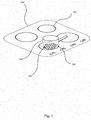
- the cooker 100 is a hob 100 having plural heating areas or zones 102.
- the cooker 100 comprises four heating areas 102.
- the cooker 100 may optionally also comprise at least one of a grill and an oven.
- the cooker 100 is an induction cooker 100, wherein the heating areas 102 each comprise an induction heating element 200 in the form of an induction coil.
- the cooker 100 may be an "electric" cooker, i.e. in which the heating elements are electrically resistive heating elements.
- the cooker 100 may be of another type having a different heating arrangement.
- a cooking vessel 104 is shown in Figure 1 placed on a heating area 102 of the cooker 100.
- the cooking vessel 104 is compatible with an induction cooker 100.
- the cooking vessel 104 is arranged to increase in temperature.
- Cooking vessels 104 that are compatible with an induction heating element 200 of an induction cooker 100 comprise a ferromagnetic base.
- the cooking vessel may be entirely made of a ferromagnetic material.
- the induction heating element 200 associated with a heating area 102 is energised by an alternating current.
- the cooking vessel 104 is placed upon the heating area 102, eddy currents are induced in the cooking vessel 104, causing an increase in the temperature of the ferromagnetic base or material of the cooking vessel 104. The heat is conducted to the remainder, body portion of the cooking vessel 104.
- the cooking vessel 104 is ideally placed directly and centrally above the heating area 102. However, as shown in Figure 1 , part of the base of the cooking vessel 104 is not in contact with or above the heating area 102, because for example the user has not placed the cooking vessel 104 centrally over the heating area 102. A first portion 106 (shown with hatching) of the base of the cooking vessel 104 which is in contact with or above the heating area 102 is caused to increase in temperature by the eddy currents induced by an induction heating element 200 of the cooker 100 and the cooking vessel 104.
- Examples described herein cause the heating element 200 of the heating area 102 to be driven to move such that heating element 200 is located centrally below the cooking vessel 104, allowing a larger portion of the base or the whole of the base of the cooking vessel 104 to be heated as intended by eddy currents induced in the cooking vessel 104 by the heating element 200 of the cooker 100. This improves the efficiency and effectiveness of the heating of the cooking vessel 104.
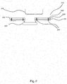
- At least one bi-metallic element 202 is associated with the heating element 200, to drive movement of the heating element 200 when the heating element 200 is not centrally aligned with the cooking vessel 104.
- the bi-metallic element 202 is composed of a first metal layer 204 and a second metal layer 206.
- the thermal expansion coefficients of the two layers 204, 206 are different such that as the bi-metallic element 202 is heated, one layer expands more than the other.
- the first (lower) metal layer 204 expands more than the second (upper) metal layer 206, though this can be reversed in other arrangements.
- the metal layers 204, 206 of the bi-metallic element 202 are fixedly joined together by fixed connections 208, such as straps, or otherwise fixed to each other at or towards each end of the bi-metallic element 202 and/or along the length of the bi-metallic element 202.
- fixed connections 208 such as straps, or otherwise fixed to each other at or towards each end of the bi-metallic element 202 and/or along the length of the bi-metallic element 202.
- the cooking vessel 104 is held above the heating element 200 by a supporting structure 210.
- the supporting structure 210 is made, wholly or in part, of a material that has a high thermally conductivity, to allow the bi-metallic element(s) 202 to be heated when it underlies at least in part the cooking vessel 104.
- the support structure 210 may in one example be entirely made of the material having a high thermally conductivity, or, in another example, only the heating areas 102 and optionally also the region of the supporting structure 210 immediately surrounding the heating areas 102 may be made of the thermally conductive material.
- the cooking vessel 104 When the cooker 100 is in operation and the cooking vessel 104 is not fully or centrally aligned with the heating element 200, the cooking vessel 104 will be overlying (at least) one bi-metallic element 202'.
- the one bi-metallic element 202' is in thermal contact with the cooking vessel 104, and so heat transferring from the cooking vessel 104 to the bi-metallic element 202' causes the bi-metallic element 202' to curve downwards.
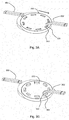
- the cooker 100 in this example comprises a connector arrangement 300, 302, 304 for connecting the bi-metallic elements 202 to the heating element 200.
- the connector arrangement 300, 302, 304 is arranged to cause a bi-metallic element 202 to selectively engage with the heating element 200 when the bi-metallic element 202 deforms when heated by conducting heat from the cooking vessel 104. This will cause the bi-metallic element 202 to drive the now engaged heating element 200 to move when the at least one bi-metallic element 202 deforms.
- the connector arrangement 300, 302, 304 is arranged to cause the bi-metallic element 202 to disengage from the heating element 200 when the bi-metallic element 202 returns to its default, rest state.
- the connector arrangement 300, 302, 304 comprises a protrusion 300 on the bi-metallic element 200, the protrusion 300 being arranged to cause the bi-metallic element 202' to engage with the heating element 200 when the bi-metallic element 202' is heated.
- the protrusion 300 may, for example, be a hook or tongue or the like, arranged to form a connection with the heating element 200 when the bi-metallic element 202 curves down towards the heating element 200.
- the connector arrangement 300, 302, 304 comprises a groove (not shown) on the bi-metallic element 200, the groove being arranged to cause the bi-metallic element 202' to engage with the heating element 200 when the bi-metallic element 202' is heated.
- the connector arrangement 300, 302, 304 comprises at least one hole or groove 302 located on a surface of the heating element 200 parallel to the base of the cooking vessel 104.
- the groove 302 is a blind recess 302.
- the bi-metallic element 202 is arranged to be positioned above or below the groove 302 of the heating element 200 such that when the bi-metallic element 202 heats up and curves towards the heating element 200, in one example the protrusion 300 of the bi-metallic element 202 engages with the corresponding groove 302 of the heating element 200.
- the curved bi-metallic element 202' engages with the heating element 200 by virtue of the protrusion 300 of the bi-metallic element 202' falling into the groove 302 of the heating element 200.
- the heating element 200 is drawn towards the deformed bi-metallic element 202, such that the heating element 200 is brought into alignment with the cooking vessel 104.
- the heating element 200 may comprise at least one protrusion 304 located on a surface of the heating element 200 parallel to the base of the cooking vessel 104.
- the protrusion 304 may be for example an upstanding block or a square clip or square nail.
- a protrusion 300 of the bi-metallic element 202' engages with a square nail 304 of the heating element 200, by virtue of the square nail 304 of the heating element 200 being hooked by the protrusion 300 of the bi-metallic element 202'.
- the bi-metallic element 202' may comprise a groove for engaging with a corresponding protrusion 304 of the heating element 200, when the bi-metallic element 202' heats up and curves towards the heating element 200.
- One bi-metallic element 202 may be sufficient in some scenarios, such as for example when the cooker 100 is small enough to only require limited movement of the heating element 200 or if the cooking vessel 104 tends always to be positioned off-centre in a particular direction (for example, because of physical constraints on the locating of the cooking vessel 104 on the cooker 100).
- a heating element 200 having plural bi-metallic elements 202 gives greater options and flexibility in controlling the movement of the heating element 200.
- An advantage of having plural bi-metallic elements 202 is that the heating element 200 can be moved in a number of different directions depending on which bi-metallic element(s) 202 is/are hot relative to each other as a result of being in thermal contact with the cooking vessel 104.
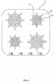
- a cooking vessel 104 is centred perfectly on the heating area 102 comprising plural bi-metallic elements 202 as shown schematically in Figures 2 to 4
- all of the bi-metallic elements 202 may be heated equally by conduction of heat from the cooking vessel 104 (or not heated at all if the cooking vessel 104 is not overlying any of the bi-metallic elements 202), resulting in no temperature differential between the bi-metallic elements 202.
- the bi-metallic elements 202 deform evenly (or remain flat if the bi-metallic elements 202 are not heated at all), and the heating element 200 is therefore not driven to move.
- the cooking vessel 104 when the cooker 100 is in operation and the cooking vessel 104 is not fully or centrally aligned with the heating element 200, the cooking vessel 104 will be overlying at least one bi-metallic element 202' more than it overlies the other bi-metallic element(s) 202.
- the at least one bi-metallic element 202' is caused to heat up and drive the heating element 200 to move.
- the heating element 200 is driven in the direction of the at least one bi-metallic element 202' underlying the cooking vessel 104 to be more accurately aligned with the cooking vessel 104.
- the bi-metallic element(s) 202 cool down, for example to ambient temperature, the bi-metallic element(s) 202 return(s) to their default linear shape and lie flat within the cooker 100, and the heating element 200 is restored to a default location in the cooker 100.
- the bi-metallic elements 202 may not be heated and therefore lie flat when the cooker 100 is turned off, when, for example, there is no cooking vessel 104 present on the cooker 100, or when the cooker 100 is functioning and the cooking vessel 104 is centrally aligned with the heating element 200.
- each heating area 102 of the cooker 100 comprises a heating element 200 and eight bi-metallic element 202, such that the heating element 200 is able to be driven in a plurality of directions based on at least one bi-metallic element 202 heating up.
- the bi-metallic elements 202 extend radially from the heating element 200.
- the bi-metallic elements 202 are partially above the heating element 200, and partially in the area immediately outside the heating element 200. If, when the cooker 100 is functioning, a cooking vessel 104 is perfectly centred above the heating element 200 and overlying equally above all of the bi-metallic elements 202, the bi-metallic elements 202 are heated uniformly. Therefore the bi-metallic elements 202 all deform uniformly, and the heating element 200 will not be moved in any one direction.
- the bi-metallic elements may be positioned entirely outside the area of the heating element 200.
- the heating element 200 will not be driven to move.
- at least one bi-metallic element 202 may become in thermal contact with the cooking vessel 104. The at least one bi-metallic element 202 will heat up and be caused to deform, such that the heating element 200 is driven to move to be centrally aligned beneath the cooking vessel 104.
- the cooker 100 comprises at least one elastic member (not shown), such as for example a spring or an elastic cable or the like.
- the elastic member is connected to the heating element 200 and arranged to facilitate movement of the heating element 200 when a bi-metallic element 202 is caused to heat up and therefore pull the heating element 200.
- a restorative member such as for example a spring or an elastic cable or the like, may be connected to the heating element 200 and arranged to restore or assist restoration of the heating element 200 to its default position within the cooker 100.
Landscapes
- Physics & Mathematics (AREA)
- Electromagnetism (AREA)
- Engineering & Computer Science (AREA)
- Food Science & Technology (AREA)
- Cookers (AREA)
Priority Applications (2)
| Application Number | Priority Date | Filing Date | Title |
|---|---|---|---|
| EP18156812.2A EP3528595B1 (de) | 2018-02-14 | 2018-02-14 | Kocher |
| US16/276,407 US11178733B2 (en) | 2018-02-14 | 2019-02-14 | Cooker |
Applications Claiming Priority (1)
| Application Number | Priority Date | Filing Date | Title |
|---|---|---|---|
| EP18156812.2A EP3528595B1 (de) | 2018-02-14 | 2018-02-14 | Kocher |
Publications (2)
| Publication Number | Publication Date |
|---|---|
| EP3528595A1 true EP3528595A1 (de) | 2019-08-21 |
| EP3528595B1 EP3528595B1 (de) | 2020-08-19 |
Family
ID=61226420
Family Applications (1)
| Application Number | Title | Priority Date | Filing Date |
|---|---|---|---|
| EP18156812.2A Active EP3528595B1 (de) | 2018-02-14 | 2018-02-14 | Kocher |
Country Status (2)
| Country | Link |
|---|---|
| US (1) | US11178733B2 (de) |
| EP (1) | EP3528595B1 (de) |
Families Citing this family (2)
| Publication number | Priority date | Publication date | Assignee | Title |
|---|---|---|---|---|
| DE102019216198B4 (de) * | 2019-10-21 | 2025-01-30 | E.G.O. Elektro-Gerätebau GmbH | Kochfeld |
| US20220074598A1 (en) * | 2020-09-09 | 2022-03-10 | Nuwave, Llc | Temperature Control System for Cooking Appliances |
Citations (4)
| Publication number | Priority date | Publication date | Assignee | Title |
|---|---|---|---|---|
| DE1106440B (de) * | 1956-02-04 | 1961-05-10 | Max Baermann | Vorrichtung zum Erwaermen des Inhaltes von ganz oder teilweise aus elektrisch bzw. magnetisch gut leitendem Werkstoff bestehenden Behaeltern, insbesondere zum Erhitzen der Speisen in Kochtoepfen, Pfannen od. dgl. mittels eines umlaufenden, mechanisch angetriebenen mehrpoligen Magnetsystems |
| EP0183163A1 (de) * | 1984-11-27 | 1986-06-04 | Mitsubishi Denki Kabushiki Kaisha | Induktionsheizgerät |
| EP1339257A2 (de) * | 2002-02-26 | 2003-08-27 | Strix Limited | Elektrische Wassererhitzungsgeräte |
| EP3244694A1 (de) * | 2016-05-11 | 2017-11-15 | Miele & Cie. KG | Kochsystem mit kochstelle und kochgeschirr |
Family Cites Families (4)
| Publication number | Priority date | Publication date | Assignee | Title |
|---|---|---|---|---|
| JPS54104052A (en) | 1978-02-01 | 1979-08-15 | Mitsubishi Electric Corp | Induction heater |
| DE3535687A1 (de) * | 1985-10-05 | 1987-04-09 | Braun Ag | Warmhalteplatte, insbesondere fuer eine elektrische kaffeemaschine |
| JP4843387B2 (ja) | 2006-06-14 | 2011-12-21 | クリナップ株式会社 | システムキッチン |
| US20170019957A1 (en) * | 2015-07-17 | 2017-01-19 | Bernard Fryshman | Induction cooking and heating systems |
-
2018
- 2018-02-14 EP EP18156812.2A patent/EP3528595B1/de active Active
-
2019
- 2019-02-14 US US16/276,407 patent/US11178733B2/en active Active
Patent Citations (4)
| Publication number | Priority date | Publication date | Assignee | Title |
|---|---|---|---|---|
| DE1106440B (de) * | 1956-02-04 | 1961-05-10 | Max Baermann | Vorrichtung zum Erwaermen des Inhaltes von ganz oder teilweise aus elektrisch bzw. magnetisch gut leitendem Werkstoff bestehenden Behaeltern, insbesondere zum Erhitzen der Speisen in Kochtoepfen, Pfannen od. dgl. mittels eines umlaufenden, mechanisch angetriebenen mehrpoligen Magnetsystems |
| EP0183163A1 (de) * | 1984-11-27 | 1986-06-04 | Mitsubishi Denki Kabushiki Kaisha | Induktionsheizgerät |
| EP1339257A2 (de) * | 2002-02-26 | 2003-08-27 | Strix Limited | Elektrische Wassererhitzungsgeräte |
| EP3244694A1 (de) * | 2016-05-11 | 2017-11-15 | Miele & Cie. KG | Kochsystem mit kochstelle und kochgeschirr |
Also Published As
| Publication number | Publication date |
|---|---|
| US11178733B2 (en) | 2021-11-16 |
| US20190254124A1 (en) | 2019-08-15 |
| EP3528595B1 (de) | 2020-08-19 |
Similar Documents
| Publication | Publication Date | Title |
|---|---|---|
| EP2048914B1 (de) | Kochvorrichtung mit Induktionserhitzungselement | |
| JP3174371U (ja) | 電磁加熱型焼肉用装置 | |
| US20230055637A1 (en) | Heating assembly for cooking appliance | |
| US11178733B2 (en) | Cooker | |
| JPH05101870A (ja) | 加熱装置を備えた家庭用料理器具 | |
| US10499459B2 (en) | Cooktop appliance and temperature switch | |
| KR20130012049A (ko) | 세라믹 탄성 돌기를 갖는 인덕션 렌지 | |
| US20120118172A1 (en) | Cooking appliance | |
| US7987772B2 (en) | Passive heater | |
| US7385162B2 (en) | Heater unit and electric cooker equipped therewith | |
| JP2009123603A (ja) | 誘導加熱調理器 | |
| US3258580A (en) | Hold-down means for convoluted sheathed heater | |
| US20250142680A1 (en) | Heating system | |
| KR20100117410A (ko) | 유도가열 주방용기에 사용되는 Cu함유 스텐레스강제 유도전열판 | |
| EP3297399B1 (de) | Kochvorrichtung mit induktionserhitzung | |
| JP3698116B2 (ja) | 誘導加熱調理器用加熱プレート及び鍋 | |
| US20220151434A1 (en) | Cooking appliance employing radiative flux | |
| JP4846340B2 (ja) | 加熱調理器 | |
| JP2008295495A (ja) | 誘導加熱用の非導通性鍋とそれを用いた誘導加熱調理器 | |
| JP4036189B2 (ja) | 誘導加熱調理器用加熱容器 | |
| JPH10189233A (ja) | 誘導加熱調理器 | |
| JP4970092B2 (ja) | 誘導加熱調理器 | |
| JPH03714Y2 (de) | ||
| CN107864526A (zh) | 一种自适应电磁炉 | |
| JPS63207086A (ja) | 誘導加熱調理器用の被加熱体 |
Legal Events
| Date | Code | Title | Description |
|---|---|---|---|
| PUAI | Public reference made under article 153(3) epc to a published international application that has entered the european phase |
Free format text: ORIGINAL CODE: 0009012 |
|
| STAA | Information on the status of an ep patent application or granted ep patent |
Free format text: STATUS: THE APPLICATION HAS BEEN PUBLISHED |
|
| AK | Designated contracting states |
Kind code of ref document: A1 Designated state(s): AL AT BE BG CH CY CZ DE DK EE ES FI FR GB GR HR HU IE IS IT LI LT LU LV MC MK MT NL NO PL PT RO RS SE SI SK SM TR |
|
| AX | Request for extension of the european patent |
Extension state: BA ME |
|
| STAA | Information on the status of an ep patent application or granted ep patent |
Free format text: STATUS: REQUEST FOR EXAMINATION WAS MADE |
|
| 17P | Request for examination filed |
Effective date: 20200129 |
|
| GRAP | Despatch of communication of intention to grant a patent |
Free format text: ORIGINAL CODE: EPIDOSNIGR1 |
|
| RBV | Designated contracting states (corrected) |
Designated state(s): AL AT BE BG CH CY CZ DE DK EE ES FI FR GB GR HR HU IE IS IT LI LT LU LV MC MK MT NL NO PL PT RO RS SE SI SK SM TR |
|
| STAA | Information on the status of an ep patent application or granted ep patent |
Free format text: STATUS: GRANT OF PATENT IS INTENDED |
|
| INTG | Intention to grant announced |
Effective date: 20200305 |
|
| GRAS | Grant fee paid |
Free format text: ORIGINAL CODE: EPIDOSNIGR3 |
|
| GRAA | (expected) grant |
Free format text: ORIGINAL CODE: 0009210 |
|
| STAA | Information on the status of an ep patent application or granted ep patent |
Free format text: STATUS: THE PATENT HAS BEEN GRANTED |
|
| AK | Designated contracting states |
Kind code of ref document: B1 Designated state(s): AL AT BE BG CH CY CZ DE DK EE ES FI FR GB GR HR HU IE IS IT LI LT LU LV MC MK MT NL NO PL PT RO RS SE SI SK SM TR |
|
| REG | Reference to a national code |
Ref country code: CH Ref legal event code: EP |
|
| REG | Reference to a national code |
Ref country code: DE Ref legal event code: R096 Ref document number: 602018006945 Country of ref document: DE |
|
| REG | Reference to a national code |
Ref country code: AT Ref legal event code: REF Ref document number: 1305413 Country of ref document: AT Kind code of ref document: T Effective date: 20200915 |
|
| REG | Reference to a national code |
Ref country code: IE Ref legal event code: FG4D |
|
| REG | Reference to a national code |
Ref country code: LT Ref legal event code: MG4D |
|
| REG | Reference to a national code |
Ref country code: NL Ref legal event code: MP Effective date: 20200819 |
|
| PG25 | Lapsed in a contracting state [announced via postgrant information from national office to epo] |
Ref country code: BG Free format text: LAPSE BECAUSE OF FAILURE TO SUBMIT A TRANSLATION OF THE DESCRIPTION OR TO PAY THE FEE WITHIN THE PRESCRIBED TIME-LIMIT Effective date: 20201119 Ref country code: NO Free format text: LAPSE BECAUSE OF FAILURE TO SUBMIT A TRANSLATION OF THE DESCRIPTION OR TO PAY THE FEE WITHIN THE PRESCRIBED TIME-LIMIT Effective date: 20201119 Ref country code: GR Free format text: LAPSE BECAUSE OF FAILURE TO SUBMIT A TRANSLATION OF THE DESCRIPTION OR TO PAY THE FEE WITHIN THE PRESCRIBED TIME-LIMIT Effective date: 20201120 Ref country code: HR Free format text: LAPSE BECAUSE OF FAILURE TO SUBMIT A TRANSLATION OF THE DESCRIPTION OR TO PAY THE FEE WITHIN THE PRESCRIBED TIME-LIMIT Effective date: 20200819 Ref country code: PT Free format text: LAPSE BECAUSE OF FAILURE TO SUBMIT A TRANSLATION OF THE DESCRIPTION OR TO PAY THE FEE WITHIN THE PRESCRIBED TIME-LIMIT Effective date: 20201221 Ref country code: LT Free format text: LAPSE BECAUSE OF FAILURE TO SUBMIT A TRANSLATION OF THE DESCRIPTION OR TO PAY THE FEE WITHIN THE PRESCRIBED TIME-LIMIT Effective date: 20200819 Ref country code: SE Free format text: LAPSE BECAUSE OF FAILURE TO SUBMIT A TRANSLATION OF THE DESCRIPTION OR TO PAY THE FEE WITHIN THE PRESCRIBED TIME-LIMIT Effective date: 20200819 Ref country code: FI Free format text: LAPSE BECAUSE OF FAILURE TO SUBMIT A TRANSLATION OF THE DESCRIPTION OR TO PAY THE FEE WITHIN THE PRESCRIBED TIME-LIMIT Effective date: 20200819 |
|
| REG | Reference to a national code |
Ref country code: AT Ref legal event code: MK05 Ref document number: 1305413 Country of ref document: AT Kind code of ref document: T Effective date: 20200819 |
|
| PG25 | Lapsed in a contracting state [announced via postgrant information from national office to epo] |
Ref country code: IS Free format text: LAPSE BECAUSE OF FAILURE TO SUBMIT A TRANSLATION OF THE DESCRIPTION OR TO PAY THE FEE WITHIN THE PRESCRIBED TIME-LIMIT Effective date: 20201219 Ref country code: LV Free format text: LAPSE BECAUSE OF FAILURE TO SUBMIT A TRANSLATION OF THE DESCRIPTION OR TO PAY THE FEE WITHIN THE PRESCRIBED TIME-LIMIT Effective date: 20200819 Ref country code: PL Free format text: LAPSE BECAUSE OF FAILURE TO SUBMIT A TRANSLATION OF THE DESCRIPTION OR TO PAY THE FEE WITHIN THE PRESCRIBED TIME-LIMIT Effective date: 20200819 Ref country code: RS Free format text: LAPSE BECAUSE OF FAILURE TO SUBMIT A TRANSLATION OF THE DESCRIPTION OR TO PAY THE FEE WITHIN THE PRESCRIBED TIME-LIMIT Effective date: 20200819 Ref country code: NL Free format text: LAPSE BECAUSE OF FAILURE TO SUBMIT A TRANSLATION OF THE DESCRIPTION OR TO PAY THE FEE WITHIN THE PRESCRIBED TIME-LIMIT Effective date: 20200819 |
|
| PG25 | Lapsed in a contracting state [announced via postgrant information from national office to epo] |
Ref country code: SM Free format text: LAPSE BECAUSE OF FAILURE TO SUBMIT A TRANSLATION OF THE DESCRIPTION OR TO PAY THE FEE WITHIN THE PRESCRIBED TIME-LIMIT Effective date: 20200819 Ref country code: CZ Free format text: LAPSE BECAUSE OF FAILURE TO SUBMIT A TRANSLATION OF THE DESCRIPTION OR TO PAY THE FEE WITHIN THE PRESCRIBED TIME-LIMIT Effective date: 20200819 Ref country code: DK Free format text: LAPSE BECAUSE OF FAILURE TO SUBMIT A TRANSLATION OF THE DESCRIPTION OR TO PAY THE FEE WITHIN THE PRESCRIBED TIME-LIMIT Effective date: 20200819 Ref country code: RO Free format text: LAPSE BECAUSE OF FAILURE TO SUBMIT A TRANSLATION OF THE DESCRIPTION OR TO PAY THE FEE WITHIN THE PRESCRIBED TIME-LIMIT Effective date: 20200819 Ref country code: EE Free format text: LAPSE BECAUSE OF FAILURE TO SUBMIT A TRANSLATION OF THE DESCRIPTION OR TO PAY THE FEE WITHIN THE PRESCRIBED TIME-LIMIT Effective date: 20200819 |
|
| REG | Reference to a national code |
Ref country code: DE Ref legal event code: R097 Ref document number: 602018006945 Country of ref document: DE |
|
| PG25 | Lapsed in a contracting state [announced via postgrant information from national office to epo] |
Ref country code: ES Free format text: LAPSE BECAUSE OF FAILURE TO SUBMIT A TRANSLATION OF THE DESCRIPTION OR TO PAY THE FEE WITHIN THE PRESCRIBED TIME-LIMIT Effective date: 20200819 Ref country code: AT Free format text: LAPSE BECAUSE OF FAILURE TO SUBMIT A TRANSLATION OF THE DESCRIPTION OR TO PAY THE FEE WITHIN THE PRESCRIBED TIME-LIMIT Effective date: 20200819 Ref country code: AL Free format text: LAPSE BECAUSE OF FAILURE TO SUBMIT A TRANSLATION OF THE DESCRIPTION OR TO PAY THE FEE WITHIN THE PRESCRIBED TIME-LIMIT Effective date: 20200819 |
|
| PLBE | No opposition filed within time limit |
Free format text: ORIGINAL CODE: 0009261 |
|
| STAA | Information on the status of an ep patent application or granted ep patent |
Free format text: STATUS: NO OPPOSITION FILED WITHIN TIME LIMIT |
|
| PG25 | Lapsed in a contracting state [announced via postgrant information from national office to epo] |
Ref country code: SK Free format text: LAPSE BECAUSE OF FAILURE TO SUBMIT A TRANSLATION OF THE DESCRIPTION OR TO PAY THE FEE WITHIN THE PRESCRIBED TIME-LIMIT Effective date: 20200819 |
|
| 26N | No opposition filed |
Effective date: 20210520 |
|
| PG25 | Lapsed in a contracting state [announced via postgrant information from national office to epo] |
Ref country code: IT Free format text: LAPSE BECAUSE OF FAILURE TO SUBMIT A TRANSLATION OF THE DESCRIPTION OR TO PAY THE FEE WITHIN THE PRESCRIBED TIME-LIMIT Effective date: 20200819 |
|
| PG25 | Lapsed in a contracting state [announced via postgrant information from national office to epo] |
Ref country code: SI Free format text: LAPSE BECAUSE OF FAILURE TO SUBMIT A TRANSLATION OF THE DESCRIPTION OR TO PAY THE FEE WITHIN THE PRESCRIBED TIME-LIMIT Effective date: 20200819 |
|
| PG25 | Lapsed in a contracting state [announced via postgrant information from national office to epo] |
Ref country code: MC Free format text: LAPSE BECAUSE OF FAILURE TO SUBMIT A TRANSLATION OF THE DESCRIPTION OR TO PAY THE FEE WITHIN THE PRESCRIBED TIME-LIMIT Effective date: 20200819 |
|
| REG | Reference to a national code |
Ref country code: BE Ref legal event code: MM Effective date: 20210228 |
|
| PG25 | Lapsed in a contracting state [announced via postgrant information from national office to epo] |
Ref country code: LI Free format text: LAPSE BECAUSE OF NON-PAYMENT OF DUE FEES Effective date: 20210228 Ref country code: LU Free format text: LAPSE BECAUSE OF NON-PAYMENT OF DUE FEES Effective date: 20210214 Ref country code: CH Free format text: LAPSE BECAUSE OF NON-PAYMENT OF DUE FEES Effective date: 20210228 |
|
| PG25 | Lapsed in a contracting state [announced via postgrant information from national office to epo] |
Ref country code: IE Free format text: LAPSE BECAUSE OF NON-PAYMENT OF DUE FEES Effective date: 20210214 Ref country code: FR Free format text: LAPSE BECAUSE OF NON-PAYMENT OF DUE FEES Effective date: 20210228 |
|
| PG25 | Lapsed in a contracting state [announced via postgrant information from national office to epo] |
Ref country code: BE Free format text: LAPSE BECAUSE OF NON-PAYMENT OF DUE FEES Effective date: 20210228 |
|
| PG25 | Lapsed in a contracting state [announced via postgrant information from national office to epo] |
Ref country code: CY Free format text: LAPSE BECAUSE OF FAILURE TO SUBMIT A TRANSLATION OF THE DESCRIPTION OR TO PAY THE FEE WITHIN THE PRESCRIBED TIME-LIMIT Effective date: 20200819 |
|
| PG25 | Lapsed in a contracting state [announced via postgrant information from national office to epo] |
Ref country code: HU Free format text: LAPSE BECAUSE OF FAILURE TO SUBMIT A TRANSLATION OF THE DESCRIPTION OR TO PAY THE FEE WITHIN THE PRESCRIBED TIME-LIMIT; INVALID AB INITIO Effective date: 20180214 |
|
| PG25 | Lapsed in a contracting state [announced via postgrant information from national office to epo] |
Ref country code: MK Free format text: LAPSE BECAUSE OF FAILURE TO SUBMIT A TRANSLATION OF THE DESCRIPTION OR TO PAY THE FEE WITHIN THE PRESCRIBED TIME-LIMIT Effective date: 20200819 |
|
| PG25 | Lapsed in a contracting state [announced via postgrant information from national office to epo] |
Ref country code: MT Free format text: LAPSE BECAUSE OF FAILURE TO SUBMIT A TRANSLATION OF THE DESCRIPTION OR TO PAY THE FEE WITHIN THE PRESCRIBED TIME-LIMIT Effective date: 20200819 |
|
| REG | Reference to a national code |
Ref country code: DE Ref legal event code: R082 Ref document number: 602018006945 Country of ref document: DE Representative=s name: WESTPHAL, MUSSGNUG & PARTNER PATENTANWAELTE MI, DE |
|
| PGFP | Annual fee paid to national office [announced via postgrant information from national office to epo] |
Ref country code: GB Payment date: 20260219 Year of fee payment: 9 |
|
| PGFP | Annual fee paid to national office [announced via postgrant information from national office to epo] |
Ref country code: DE Payment date: 20260218 Year of fee payment: 9 |
|
| PGFP | Annual fee paid to national office [announced via postgrant information from national office to epo] |
Ref country code: TR Payment date: 20260213 Year of fee payment: 9 |