EP3528621B1 - System and method for aquaculture using floating closed containment farming - Google Patents
System and method for aquaculture using floating closed containment farming Download PDFInfo
- Publication number
- EP3528621B1 EP3528621B1 EP17863211.3A EP17863211A EP3528621B1 EP 3528621 B1 EP3528621 B1 EP 3528621B1 EP 17863211 A EP17863211 A EP 17863211A EP 3528621 B1 EP3528621 B1 EP 3528621B1
- Authority
- EP
- European Patent Office
- Prior art keywords
- water
- hull
- tank
- aquaculture
- chute
- Prior art date
- Legal status (The legal status is an assumption and is not a legal conclusion. Google has not performed a legal analysis and makes no representation as to the accuracy of the status listed.)
- Active
Links
Images


Classifications
-
- A—HUMAN NECESSITIES
- A01—AGRICULTURE; FORESTRY; ANIMAL HUSBANDRY; HUNTING; TRAPPING; FISHING
- A01K—ANIMAL HUSBANDRY; AVICULTURE; APICULTURE; PISCICULTURE; FISHING; REARING OR BREEDING ANIMALS, NOT OTHERWISE PROVIDED FOR; NEW BREEDS OF ANIMALS
- A01K61/00—Culture of aquatic animals
- A01K61/60—Floating cultivation devices, e.g. rafts or floating fish-farms
- A01K61/65—Connecting or mooring devices therefor
-
- A—HUMAN NECESSITIES
- A01—AGRICULTURE; FORESTRY; ANIMAL HUSBANDRY; HUNTING; TRAPPING; FISHING
- A01K—ANIMAL HUSBANDRY; AVICULTURE; APICULTURE; PISCICULTURE; FISHING; REARING OR BREEDING ANIMALS, NOT OTHERWISE PROVIDED FOR; NEW BREEDS OF ANIMALS
- A01K61/00—Culture of aquatic animals
- A01K61/60—Floating cultivation devices, e.g. rafts or floating fish-farms
-
- B—PERFORMING OPERATIONS; TRANSPORTING
- B63—SHIPS OR OTHER WATERBORNE VESSELS; RELATED EQUIPMENT
- B63B—SHIPS OR OTHER WATERBORNE VESSELS; EQUIPMENT FOR SHIPPING
- B63B35/00—Vessels or similar floating structures specially adapted for specific purposes and not otherwise provided for
- B63B35/44—Floating buildings, stores, drilling platforms, or workshops, e.g. carrying water-oil separating devices
-
- B—PERFORMING OPERATIONS; TRANSPORTING
- B63—SHIPS OR OTHER WATERBORNE VESSELS; RELATED EQUIPMENT
- B63B—SHIPS OR OTHER WATERBORNE VESSELS; EQUIPMENT FOR SHIPPING
- B63B11/00—Interior subdivision of hulls
- B63B11/04—Constructional features of bunkers, e.g. structural fuel tanks, or ballast tanks, e.g. with elastic walls
-
- B—PERFORMING OPERATIONS; TRANSPORTING
- B63—SHIPS OR OTHER WATERBORNE VESSELS; RELATED EQUIPMENT
- B63B—SHIPS OR OTHER WATERBORNE VESSELS; EQUIPMENT FOR SHIPPING
- B63B21/00—Tying-up; Shifting, towing, or pushing equipment; Anchoring
- B63B21/50—Anchoring arrangements or methods for special vessels, e.g. for floating drilling platforms or dredgers
-
- B—PERFORMING OPERATIONS; TRANSPORTING
- B63—SHIPS OR OTHER WATERBORNE VESSELS; RELATED EQUIPMENT
- B63J—AUXILIARIES ON VESSELS
- B63J4/00—Arrangements of installations for treating ballast water, waste water, sewage, sludge, or refuse, or for preventing environmental pollution not otherwise provided for
- B63J4/006—Arrangements of installations for treating ballast water, waste water, sewage, sludge, or refuse, or for preventing environmental pollution not otherwise provided for for treating waste water or sewage
-
- B—PERFORMING OPERATIONS; TRANSPORTING
- B63—SHIPS OR OTHER WATERBORNE VESSELS; RELATED EQUIPMENT
- B63B—SHIPS OR OTHER WATERBORNE VESSELS; EQUIPMENT FOR SHIPPING
- B63B35/00—Vessels or similar floating structures specially adapted for specific purposes and not otherwise provided for
- B63B35/44—Floating buildings, stores, drilling platforms, or workshops, e.g. carrying water-oil separating devices
- B63B2035/4493—Floating structures supporting vegetation, such as trees, reeds, crops, plants, or the like, e.g. flexible structures
-
- Y—GENERAL TAGGING OF NEW TECHNOLOGICAL DEVELOPMENTS; GENERAL TAGGING OF CROSS-SECTIONAL TECHNOLOGIES SPANNING OVER SEVERAL SECTIONS OF THE IPC; TECHNICAL SUBJECTS COVERED BY FORMER USPC CROSS-REFERENCE ART COLLECTIONS [XRACs] AND DIGESTS
- Y02—TECHNOLOGIES OR APPLICATIONS FOR MITIGATION OR ADAPTATION AGAINST CLIMATE CHANGE
- Y02A—TECHNOLOGIES FOR ADAPTATION TO CLIMATE CHANGE
- Y02A40/00—Adaptation technologies in agriculture, forestry, livestock or agroalimentary production
- Y02A40/80—Adaptation technologies in agriculture, forestry, livestock or agroalimentary production in fisheries management
- Y02A40/81—Aquaculture, e.g. of fish
Definitions
- the present invention relates to off-shore floatable closed containment aquaculture production apparatuses.
- Aquaculture refers to farming of aquatic animals such as fish, shellfish and cultivation of plants in water.
- the term aquaculture refers to the cultivation of both marine and freshwater species. Such cultivation may be on land, in inland ponds or raised tanks, or in open sea or ocean using net cages.
- One object of the present invention is therefore to address the problems of the existing art and / or to provide a choice that is useful in the art.
- NO 20100465 A1 relates to tanks and bulk carriers having tanks that can be rebuilt to become fish and shellfish farms.
- US 4930444 A relates to a method of fishing for swimming fish while nourishing the fish with sea water containing plankton and apparatus therefor.
- US 5762024 A relates to an aquaculture system for growing aquatic animals such as fish and crustaceans, in which a rigid-walled floating tank is positioned in a body of water.
- the invention is capable of significantly increasing aquaculture production yield over other existing methods so as to provide food security at lower cost to all, yet safeguarding the environment, society and community, and achieving an economic advantage.
- closed cage apparatus as a closed containment fish farming (CCFF) method provided by the invention
- all pollution will be reduced, no fish can escape, no transfer of disease and parasite to the wild will take place.
- This invention with closed containment, besides being capable of lasting more than 10 years without the need for docking the Eco-Ark TM whereas existing open net methods may not last that long.
- This invention also runs at minimum operation costs due to less labour, less fish meal losses, less energy, less cleaning cost, no concern for algae bloom, oil pollution and water temperature changes and hence results in reduced costs as compared to existing open net cage farming methods.
- the economic advantage comes from three aspects, representing 3Rs of an eco-friendly designed ark / aquaculture production apparatus which may be commercially marketed under the name of Eco-Ark TM . Its economic advantage comes from (i) Reuse, (ii) Reduce, (iii) Recycle to protect the environment. This will be demonstrated throughout this inventive description.
- the design philosophy of the Eco-Ark TM is to ensure that the investment cost by way of fish production per kilogram per annum must be competitive to the existing methods.
- the cost of Eco-Ark TM after prototype may be reduced by recycled steel plate and operation cost, e.g. cost of energy, may be reduced using green renewable energy from the solar energy as the base to power production of hydrogen and uses hydrogen fuel cell technology amongst others to provide electricity.
- the invention aims to be ecologically friendly and socially responsible, respect the natural environment or nature, bring back nature and use nature to solve our modern day's problems and issues as the world population increases year-on-year.
- a floatable closed containment aquaculture production apparatus comprises:
- an aquaculture production and transfer system comprises:
- an aquaculture production and transfer method comprises:
- Embodiments described in the context of one of the methods or devices or systems are analogously valid for the other methods or devices or systems. Similarly, embodiments described in the context of a method are analogously valid for a system or device, and vice versa.
- each other denotes a reciprocal relation between two or more objects, depending on the number of objects involved.
- Coupled and related terms are used in an operational sense and are not necessarily limited to a direct physical connection or coupling.
- two devices may be coupled directly, or via one or more intermediary devices.
- devices may be coupled in such a way that fluids may be passed there between without sharing physical connection with each other. Based on the present disclosure, a person of ordinary skill in the art will appreciate a variety of ways in which coupling exists in accordance with the aforementioned definition.
- pipe includes a reference to a rigid pipe or a flexible pipe or a combination thereof to provide a conduit for fluid flow, or any types of conduit and channel.
- body of water and “water body” refer to marine waters, e.g. sea, ocean, and to inland fresh or salt waters, e.g. lakes, reservoirs, rivers.
- aquatic refers to cultivation or farming of aquatic animals and/or plants in natural or controlled, and marine or freshwater environments primarily for human consumption or use, and may further refer to aquatic animals, e.g. fish, shellfish, crustaceans, other aquatic (marine or freshwater) organisms.
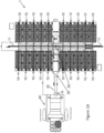
- an aquaculture production and transfer system 1 is provided (see Figures 1A and 1H ).
- the system 1 comprises a plurality of floatable closed containment aquaculture production apparatuses 10 configured to cultivate or farm aquatic animals, a station keeping apparatus 20 coupled to at least one of the production apparatuses 10, a custodian transfer apparatus 30 configured to receive aquatic animals from various aquaculture production apparatuses 10 or farms and further configured to transport live aquatic animals to an amalgamated facility 40 which is separated from the aquaculture production apparatuses 10 by a body of water.
- the amalgamated facility 40 may be located around 100 metres from the aquaculture production apparatuses 10.
- the aquaculture production and transfer system 1 is arranged in any body of water of sufficient depth.
- the system 1 may be arranged in marine waters, e.g. offshore in sea and ocean, or fresh or salt waters, e.g. lakes and rivers.
- the apparatus 10 may be configured to be floatable or floating.
- the apparatus 10 may be movable, e.g. by towing or self-propulsion.
- the apparatus 10 may be heavily submerged and, in some embodiments, mostly or substantially or almost submerged, e.g. in some embodiments, a depth of the hull 101, which is defined by the outer side portions 101c and the bottom portion 101a, is at least 90% submerged under water surface.
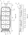
- a top plan profile is a rectangle ( Figure 1A ), octagon ( Figure 1C ), square ( Figure 1E ), hexagon ( Figure 1H ), any other polygon or non-polygon; the entire apparatus 10 may be disc-shaped, bowl-shaped or ark-shaped.
- the number of aquaculture production apparatuses 10 may range from one standalone apparatus or multiple apparatuses.
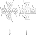
- Various arrangements of aquaculture production apparatuses 10 may be envisaged in different embodiments, e.g.
- Figure 1A shows multiple aquaculture production apparatuses 10 arranged in rows and columns
- Figure 1F shows multiple aquaculture production apparatuses 10 arranged in two rows and coupled to a station keeping apparatus 20 located between the rows
- Figure 1G shows multiple aquaculture production apparatuses 10 in a star arrangement coupled to a station keeping apparatus 20 between the rows.
- an aquaculture production apparatus 10 is provided.
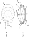
- Figures 1B and 1C illustrating one embodiment which is hexadecagon-shaped, i.e. 16-sided polygon
- Figures 2A , 2B and 2C illustrating one embodiment which is rectangular-shaped
- Figures 2D , 2E , 2F and 2G illustrating one embodiment which is bowl-shaped.
- the apparatus 10 comprises a hull 101 having a hull bottom portion 101a, opposed outer hull side portions 101c extended therefrom, and a centre hull portion 101b arranged between the outer side portions 101c and extending from the bottom portion 101a to define at least one recess between the centre portion 101b and the outer side portions 101c.
- At least the bottom 101a and the outer side portions 101c include watertight walls to define at least one ballast water space 102 therebetween.
- the bottom portion 101a may include at least one bottom ballast tank and provides the baseline of the hull 101 and is submersible in operative position.
- the outer side portions 101c include void spaces or void tanks 140 to provide buoyancy to the hull 101 such that the hull 101, together with the cultivation tanks 103 which are loaded with water, remain semi-submerged in water with low freeboard when the apparatus 10, e.g. hull 101, is arranged in a body of water.
- the void spaces or void tanks 140 may be located at the ends of the outer side portions 101c, which are distal from the bottom portion 101a.
- the outer side portions 101a may include side ballast tanks.
- the centre portion 101b is arranged on or extends from the bottom portion 101a, e.g. integrally formed with the bottom portion 101a, and is located between the outer side portions 101c to provide separate recesses for receiving cultivation tanks 103.
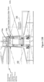
- Figure 3A is a schematic cross-sectional view taken at a mid-ship section of a hull of an aquaculture production apparatus in operative position.
- the cross-sectional profile of the hull in operative position includes a tilted down E-shape, e.g. E-shape which is 90-degree counter-clockwise rotated or rotated left by 90 degrees.
- the stem part of the E-shape corresponds to the submersible bottom portion 101a while the side arms of the E-shape correspond to the outer side portions 101c and the middle arm of the E-shape corresponds to the centre portion 101b.
- Figure 3A further shows tanks 103 (in dotted lines) arranged in the recesses.
- Figure 3B shows a hull, similar to Figure 1C , having a top plan profile and a bottom plan profile, wherein the top plan profile is larger or has larger dimensions than the bottom plan profile.
- the outer side portions 101c and bottom portion 101a form a tapered U-shape.
- Figure 3C shows the hull of Figure 3A having appendages 101d attached to the bottom 101a and outer side portions 101c.
- Figure 3D shows the hull of Figure 3A having appendages 101d attached to the outer side portions 101c.
- Figure 3E shows the hull of Figure 3A having tapered appendages 101d attached to the bottom and outer side portions 101c.
- Figure 3F shows a hull wherein the centre portion 101b may include a plurality of inner hull side portions 101f interposing a passage 106 or duct tunnel therebetween, such that an inner side portion 101f and an outer side portion 101c provide a recess therebetween to support a cultivation tank 103 arranged in the recess.
- the centre portion 101b includes ballast water space or tank 102
- the E-shape includes two U-shape structures which may be indirectly or directly attached to each other.
- Figure 3G shows the hull of Figure 3F having appendages 101d attached to the bottom and outer side portions 101c.
- Figure 3H shows the hull of Figure 3A having spud legs, e.g. columns or pipes, inserted through the outer side portions 101c and substantially parallel thereto.
- the centre portion 101b provides and/or increases strength to the hull 101. Furthermore, as shown in Figures 3A-3H , 2B and 1C , the centre portion 101b may provide support to the cultivation tanks 103.
- the centre portion is arranged generally at the centre of the hull. In embodiments where the hull is generally elongate, e.g. length is greater than beam (width), lengthwise dimension of the centre portion 101b may extend substantially along the length or longitude of the hull, e.g. substantially parallel to port and starboard of the hull.
- the centre portion 101b may be a continuous or connected structure, or discrete or unconnected structures.
- the centre portion 101b may be arranged generally at the centre of the hull and a lengthwise dimension of the centre portion may extend substantially along a diameter or centreline of the hull.
- the centre portion 101b may be provided with a through passage or duct tunnel which may provide access to various tanks 103 and an exit route for emergency evacuation.
- the centre portion 101b may be provided with a dry caisson which is closable to provide an enclosed void space to provide further buoyancy to the hull.
- the through passage or the dry caisson is arranged between opposed inner side portions wherein one of the opposed inner side portions, one of the outer side portions and a part of the bottom portion form a cross-sectional profile having two U-shapes, or two W-shapes, or two V-shapes.
- the passage or duct tunnel 106 may be enclosed at both ends by watertight hatches 118 provided at forward and aft (or rear) portions of the apparatus 10.
- the centre portion 101b includes pipelines (e.g. pipes for waste and/or aquatic animals transfer, water supply pipes, oxygen pipes), control valves of the pipelines, cables, equipment which may be located in the through passageway 106.
- pipelines e.g. pipes for waste and/or aquatic animals transfer, water supply pipes, oxygen pipes
- control valves of the pipelines e.g., control valves of the pipelines, cables, equipment which may be located in the through passageway 106.
- the cultivation tanks 103 may be provided as closed containment tanks 103 configured to create a controlled interface between the cultivated aquatic animals therein and the natural environment, such that aquatic animals such as fish may be grown in the cultivation tanks 103 without direct exposure to open sea water.
- One or more cultivation tanks 103 may be provided in each aquaculture production apparatus 10.
- Each cultivation tank 103 may be formed of rigid walls (see Figures 4A and 4B ). Each cultivation tank 103 has a top or open portion 103a which is generally exposed to air and a bottom section or generally closed portion 103b which tapers towards an intermediate point thereof.
- the tapered bottom portion 103b may include a conical portion, e.g. reverse cone, or conoidal portion.
- the top portion 103a may be provided as a cylindrical portion or with circular opening.
- the top portion may be provided with an opening having other polygonal shape, e.g. octagon, or non-polygonal shape.
- the cultivation tanks 103 are abuttedly arranged between the centre portion 101b and the outer side portions 101c, e.g. at least some of the cultivation tanks form a contiguous structure with the centre portion 101b and the outer side portions 101c to provide at least one transverse bulkhead to the hull 101 (see Figure 3A ).
- the ballast water spaces 102 are arranged into a plurality of tanks or compartments 102a along a perimeter, e.g. length or circumference of the hull 101 (see Figure 9 ), wherein each compartment 102a is configured to be ballasted in response to a discharge of aquatic animals and water from one of the cultivation tanks 103 being adjacent to the each compartment 102a to allow the hull 101 maintain equilibrium in the body of water. For example, if tank No. 1P is discharged of aquatic animals, ballast water space in compartment 102a which is most adjacent to tank No. 1P is ballasted or receives water.
- the cultivation tanks 103 are configured to receive clean water from at least one water source through an inlet channel 104a (or "in") and a plurality of water supply pipes 104b (see Figures 4A , 4D ).
- the inlet channel 104a is fluidly coupled to at least one water source, e.g. water stored in ballast water spaces 102, or a body of water external to the hull 101, to receive water therefrom.
- the plurality of water supply pipes 104b are fluidly coupled between the inlet channel 104a and the cultivation tanks 103.
- a portion of each water supply pipe 105b may be submerged in the water of a cultivation tank 103 and may include spaced openings or nozzles configured to discharge water into one of the cultivation tanks 103. The openings may be vertically spaced to produce a circular water current in the cultivation tanks 103 to compel the fish therein to exercise due to their tendency to swim against water current.
- the cultivation tanks 103 are further configured to discharge waste and/or water therefrom through a plurality of tank discharge pipes 105a and a discharge channel 105b (or "out") (see Figures 4A, 4B , 4D ).
- the tank discharge pipes 105a may fluidly couple between the cultivation tanks 103, e.g. bottom and/or top section thereof, and the discharge channel 105b.
- the discharge channel 105b may be fluidly coupled between the tank discharge pipes 105a to a discharge destination, e.g. a water body external to the hull or a waste water storage tank 116 onboard the hull.
- the tank discharge pipes 105a are fluidly coupled to bottom sections of the cultivation tanks 103 and configured to discharge water, including waste or scum, from the tank 103 to the discharge channel 105b by gravity siphonic drainage. Furthermore, the discharge channel 105b is arranged proximate to or in fluid coupling with top sections of the cultivation tanks 103 to receive an overflow from therefrom. Accordingly, water and waste from a tank 103 may be siphoned off from its top and bottom sections via tank discharge pipes 105a to the discharge channel 105b without requiring pump and/or electrical power.
- the tank discharge pipes 105a and the water supply pipes 104b are respectively configured to discharge water from the cultivation tanks 103 and supply water to the cultivation tanks 103 at a similar flow rate to maintain the volume of water in each tank 103 at a relatively constant level.
- valves may be provided at tank discharge pipes 105a and water supply pipes 104b to control flow rate of the respective pipes.
- Valves provided to discharge pipes 105a at bottom section and top section of the tank 103 may be separately adjustable to vary the flow or discharge rates therefrom.
- the inlet channel 104a and the discharge channel 105b are arranged on the centre portion 101b of the hull 101. Particularly, the inlet channel 104a is arranged over, e.g. vertically stacked above, the discharge channel 105b which is arranged over, e.g. vertically stacked above, the centre portion 101b of the hull 101 (see Figures 4A and 4D ).
- the inlet channel 104a may be provided as a trough or an open-top pipe while the discharge channel 105b may be provided as a closed-top pipe or conduit.
- the inlet channel 104a and the discharge channel 105b are arranged at an incline or sloping between a bow (or an assigned forward portion of the hull) and a stern (or an assigned aft or rear portion of the hull), or vice versa, of the hull 101 to allow flow of the clean or fish production water and waste water through the inlet channel 104a and the discharge channel 105b respectively by gravity. Accordingly, discharge of waste water via discharge channel 105b may not require pump and/or electrical power. Supply of clean water via inlet channel 104a to tanks 103 may not require pump and/or electrical power.
- a strainer (115a, see Figures 4A , 11B ) may be positioned at or proximate to the inlet of a tank discharge pipe 105a and configured to prevent entry of aquatic animals into the tank discharge pipe 105a when waste water and/or scum are being discharged from the tanks 103, and further configured to allow entry of aquatic animals into an aquaculture transfer pipe 107a when aquatic animals are being discharged from the tanks 103.
- the inlets of a tank discharge pipe 105a and an aquaculture transfer pipe 107a may be located within a chamber, arranged within the tank 103, wherein the chamber's inlet is provided with the strainer.
- the strainer may be controlled by a line or cable 115a having a first end coupled to the strainer and a second end extending out of the tank 103 for access by an operator.
- the outlet of the aquaculture transfer pipe 107a is fluidly coupled to an aquaculture transfer pump 107b which is fluidly coupled to custodian transfer apparatus 30 to transfer tank contents, including water and aquatic animals, to the custodian transfer apparatus 30.
- the aquaculture transfer pump 107b is disconnected from the tank discharge pipe 105.
- the aquaculture transfer pump 107b may be disposed in the passage 106 and movable along the passage vis-a-vis duct tunnel 106 to access any of the tanks 103.
- Display units 110 may be installed along the passage 106 to allow viewing of the tank contents (see Figures 4C , 5 , 13B ).
- cameras may be installed underwater (camera 112a) and/or above the cultivation tanks 103 (camera 112b) and communicably coupled to the display units 110.
- Biomass sensors 143 may be provided in tanks 103 (see Figures 4D and 4E ) to detect sizes of aquatic animals and therefore a determination may be made as to whether the aquatic animals in a tank, e.g. fish, may be harvested.
- the biomass sensors 143 may be communicably coupled to the display units 110 to provide fish size parameters.
- the display units 110 may also provide tank parameters e.g. water and flow.
- Inflatable oxygen rubber tanks 108 may be disposed along the port and/or starboard side for storing oxygen.
- the oxygen rubber tanks 108 may be fluidly coupled to oxygen pipes for transfer of oxygen from the rubber tanks 108 to the cultivation tanks 103.
- These rubber oxygen storage tanks 108 act also as ship-side rubber fenders and oxygen storage for emergency when the oxygen generator on board fails.
- the liquid oxygen may be used in line with the cooling refrigeration system to cool the fish production water in time when there is sudden surge in water temperature.
- Each roof 111 may include a transparent portion 111a for allowing sunlight to reach the tanks and/or at least one solar panel 111b which is configured to convert solar energy into electrical energy.
- a hydrogen converter may be electrically coupled to the solar panel and configured to receive electrical energy therefrom to convert sea water into a hydrogen fuel and an oxygen gas which is to be circulated to the tanks 103.
- the hydrogen fuel may power fuel cells for providing electrical power required by equipment on the aquaculture production apparatus. Diesel-oil driven power generating equipment and/or wind turbines may be further provided to provide electrical power.
- Wind turbine 117a and/or water turbine generator 117b may be provided to the aquaculture production apparatus 10 to generate electrical power from wind and water currents respectively.
- a perforated cover e.g. netting, may be arranged to overlay at least one cultivation tank 103 to prevent predators from entering and accessing aquatic animals in the tank 103.
- the aquaculture production apparatus 10 may include a vertically-stacked arrangement of tanks 103. Particularly, a lower tank 103 is supported between an outer side portion 101c and a centre portion 101b of a hull 101 as described in the foregoing description. A tank support structure 109 is arranged on the outer side portion and the centre portion 101b of the hull 101, and an upper tank is arranged on the tank support structure 109.
- the lower and upper tanks 103 may be provided with features described in the foregoing description.
- the aquaculture production apparatus 10 may include a Supervisory Control and Data Acquisition (SCADA) or control system configured with many sensors and cameras and all types of measuring devices; to measure size and /or biomass of aquatic animals, and control and monitor feeding rate and timing, the oxygenation and its level of dissolved oxygen and other unwanted, pH value, salinity, water quality, circulation management and power management.
- SCADA Supervisory Control and Data Acquisition
- a water production and/or circulation system may be provided to allow the aquaculture production apparatus operate on different modes wherein the inlet channel 104a is configured to alternatively receive water from a body of water external of the hull 101 or from any of the ballast water spaces 102.
- the water production and/or circulation system includes a water inlet pump 113, e.g. submersible pump located within or external of the hull, at least one valve 150 to switch or alternate between water intake between water sources by alternatively fluidly coupling inlet pump 113 to one of the water sources, a filtration system 114, inlet channel 104a, discharge channel 105b, pipes 104b, 105a, at least one sensor configured to detect an adverse condition in the body of water external of the hull, e.g.
- controller or computing unit which is communicably coupled to the sensor, and possibly other pipes and/or valves. Based on data acquired by the sensor(s), the controller or computing unit may be configured to determine a presence or an absence of adverse condition and accordingly actuate the valve 150 as well as any of the above-described components of the water production and/or production system to operate in either normal mode or recirculation mode.
- the water source is a body of water external of the hull and therefore the water inlet pump 113 is disposed in fluid communication with the body of water external of the hull and configured to draw water therefrom.
- the valve 150 may be configured to be actuated to block fluid communication with the ballast water space 102 and allow fluid communication with the body of water external of the hull 101.
- the water pump 113 is configured to transfer the drawn water to the filtration system 114a, 114b and 114c to produce filtered and sterilized high quality water.
- the inlet channel 104a is configured to receive filtered water from the filtration system 114, which is to be distributed to the various tanks 103 via the inlet channel 104a and water supply pipe 104b.
- the filtration system may include drum filters 114a, an ultraviolet or other type of sterilizer 114b, and/or biological filters 114c.
- An oxygen generator 133 may be provided and configured to inject oxygen into the water drawn into/by the water inlet pump 113.
- the discharge channel 105b is configured to receive waste water from the tanks 103, which is to be discharged into the body of water external of the hull 101. Accordingly, in this mode, water is taken from a water body external of the hull 101 to provide clean or fish production water, and waste water is returned to the same water body.
- the water source is water stored in ballast water spaces 102 and therefore the water inlet pump 113 is disposed in fluid communication with the ballast water spaces 102.
- the valve 150 may be provided at an inlet of the water inlet pump 113 and configured to be actuated to block fluid communication with the body of water external of the hull 101 and allow fluid communication with the ballast water spaces 102.
- the water inlet pump 113 is configured to draw water from the ballast water spaces 102 and transfer the water to the filtration system 114 to produce filtered water.
- the inlet channel 104a is configured to receive filtered water from the filtration system 114, which is to be distributed to the various tanks 103 via the inlet channel 104a and water supply pipes 104b as clean or fish production water.
- the discharge channel 105b is configured to receive waste water from the tanks 103, which is to be discharged into at least one waste water storage tank 116 arranged at/on the hull 101.
- a water treatment system may be provided and configured to treat the waste water in the waste water storage tank 116 to produce treated water.
- the waste water storage tank 116 is fluidly coupled to ballast water spaces 102 to allow an overflow of the waste storage tank 116, e.g. treated water, enter the ballast water spaces 102 for subsequent use or circulation to the cultivated tank 103. Accordingly, in this mode, water is taken from ballast water spaces onboard the apparatus 10 to provide clean or fish production water, and waste water may be treated before it is returned to the ballast water spaces such that the water circulation is contained within the aquaculture production apparatus 10.
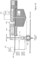
- the aquaculture production apparatus 10 may include a foreship compartment 10a, a midship compartment 10b and an aftship compartment 10c.
- the foreship compartment may include water inlet pumps 113, pump room, filtration system comprising of drum filters 114a, ultraviolet or other type of sterilizer 114b, standby emergency liquid oxygen cylinder with oxygen generating set 133 and inflatable oxygen storage tanks 108, weather vaning system, or a combination thereof.
- the midship compartment may include the aforementioned cultivation tanks 103, top and passageway 106, water inlet channel, including water supply pipes, discharge channel, discharge pipes, utilities pipelines and valves, solar panel roof, enhanced production, or a combination thereof.
- the aftship compartment may include feed storage, automated feeding system, power generation equipment, switchboard room, control room, office, laboratory, crew accommodation, fish discharge point, waste collection, water treatment, or a combination thereof. Accordingly, equipment required for aquaculture cultivation may be self-contained within each apparatus 10.
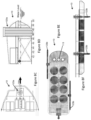
- Embodiment of Figures 1B and 1C shows a disc-shaped aquaculture production apparatus 10, e.g. hull having a disc-shaped plan profile.
- the sloping bottom of the hull 101 is provided with multiple finned blades 101e which are configured to cause the apparatus 10 to rotate due to current flow in a body of water external of the hull 101. This rotational motion may be used to generate electrical energy for use by the aquaculture production apparatus 10 and its components thereof.
- Cold water such as from the water body external of the hull 101 may be transferred through cold water inlet point 141 into ballast water spaces 102, to cool or lower the temperature of water in the cultivation tanks 103. In so doing, tropical weather regions may be able to produce farmed salmon.
- the same cold water may be transfer via air coolers 141a into the apparatus' 10 upper surface and space under the roof to cool down the ambient temperature of this space as well.
- the cold water may be waste cold water from nearby LNG (Liquefied Natural Gas) plant, e.g. the Lift-Dock Small Scale LNG and Lift-Dock - Storage Regasification Terminal (SRT).
- LNG Liquified Natural Gas
- SRT Lift-Dock - Storage Regasification Terminal
- the apparatus 10 may include a single large cultivation of fish tank 103.
- Embodiment of Figures 2D to 2F shows a bowl-shaped aquaculture production apparatus 10 which may be deployed for all weather by way of its design and having a flat bottom portion 101a with dead-ballast.
- the dead-ballast may include pig-iron with special concrete cement and/or high density barite of more than 4200kg/m 3 as permanent dead ballast to further enhance the stability of the bowl-shaped apparatus 10 in harsh water condition.
- This apparatus 10 may be configured to receive waste cold water from nearby onshore or offshore LNG (Liquefied Natural Gas) Regasification Plant to re-use the cold energy from vaporising the liquid LNG to gas. This will protect the eco-system of the site and at the same time recover this cold energy for better utilisation of energy and resources management.
- LNG Liquefied Natural Gas
- Cooling coils are arranged in the cultivation tanks 103 to cool the water in the tanks and at the same time the cleaned ballast water tank 102 can be used as a large cold transfer medium.
- the apparatus 10 may include a single large cultivation or fish tank 103.
- FIG. 2E shows a side cross-sectional view of the bowl-shaped aquaculture production apparatus taken along line A-A of Figure 2D where water supply pipes 104b for supplying water from the inlet channel 104a are lowered into the tanks 103 at various locations to create a cyclonic motion or circular water current such that waste settling at a bottom section of the tank would be discharged through tank discharge pipes 105a and waste at a top section of the tank would be discharged into the discharge channel 105b by atmospheric / gravity.
- This siphonic effect due to gravity is possible due to a height differential of the water level in the fish tank being higher than the water level of the water body external of the hull 101 in this and other embodiments.
- the fish food storage and automatic feeding system 131, oxygen generator with its storage tanks 133, the auxiliary engines and/or control room 132 may be provided on board the apparatus 10. Both ends of the passage or duct tunnel 106 may lead to both ends of the apparatus 10 and be provided with water-tight hatch cover. Filtration system comprising of drum filter 114a, with sterilizer 114b and biological filters 114c may be provided.
- Embodiment of Figure 2G shows a side cross-sectional view of a bowl-shaped aquaculture production apparatus 10 which is similar to Figures 2D to 2F .
- the apparatus 10 includes a ballast space 142a which may include a ballastible tank or dead ballast which provides stability in harsh water conditions, or a rotating turret 142b.
- the ballast 142a or rotating turret 142b may provide a station keeping apparatus 20 to the aquaculture production apparatus 10.
- a watertight roof 111c e.g.
- dome shape which may be made of heavy duty water-proof composite fibre, may be provided and configured to provide a water tight connection with the hull 101 of the apparatus 10 such that the entire apparatus 10 may be partially submerged underwater in the event of adverse weather condition with strong winds and high waves, yet maintaining its full stability, without causing damage to the equipment onboard or disruption to farming operation on the apparatus 10.
- the watertight roof 111c may include water-tight hatch openings and/or doors which are configured to allow fluid communication therethrough in an open position and to block fluid communication therethrough in a closed position to provide watertight connection with the hull 101.
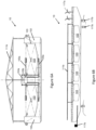
- a central waste collector pipe 11 is provided and traverses the lengths and/or beams (widths) of multiple aquaculture production apparatuses.
- the central waste collector pipe 11 may be fluidly coupled to discharge channels 105b of various aquaculture production apparatuses 10 to receive waste water therefrom.
- the central waste collector pipe 11 includes a first end portion and a second end portion which are configured to alternatively elevate relative to each other, in accordance with tide flow direction, to discharge waste from the waste collector pipe by gravity into the body of water external of the hulls. Elevation of either end portion may be performed by hydraulic means.
- Water treatment apparatus may be provided and configured to treat the waste in the waste collector pipe before the waste water is discharged into the open sea.
- At least some of the aquaculture production apparatuses 10 are coupled, e.g. mechanically coupled, to a station keeping apparatus 20, which may include weather vaning system to maintain the apparatuses 10 within a desired area or in desired positions and also to ensure that there is no cross flow of the fish waste to the fish production water suction point, e.g. water inlet of aquaculture production apparatus 10.
- a station keeping apparatus 20 which may include weather vaning system to maintain the apparatuses 10 within a desired area or in desired positions and also to ensure that there is no cross flow of the fish waste to the fish production water suction point, e.g. water inlet of aquaculture production apparatus 10.
- the station keeping apparatus 20 may be a mooring buoy which is moored to the bottom of the water body, e.g. sea bed.
- the station keeping apparatus 20 may include gravity-based foundations 121, e.g. concrete anchors or bases, secured to the bottom of the water body and four mooring lines 122 coupling the apparatus 10 to the gravity-based foundations.
- gravity-based foundations 121 e.g. concrete anchors or bases, secured to the bottom of the water body and four mooring lines 122 coupling the apparatus 10 to the gravity-based foundations.
- the station keeping apparatus 20 may be provided at the apparatus 10 and include a set of anchor or spud legs 123a, e.g. columns, pipes, which are configured to be lowered and secured to the bottom of the water body. This embodiment would allow the apparatus 10 to weather vane or pivot about the anchor or spud legs 123a.
- the station keeping apparatus 20 may be provided at the apparatus 10 and include two sets of anchor or spud legs 123b, e.g. columns, pipes, which may be movable between a horizontal (inoperative) position (see Figure 8E ) and a vertical (operative) position ( Figure 8F ).
- the anchor or spud legs 123b are configured to be rotated from the horizontal position to a vertical position, and lowered and secured to the bottom of the water body.
- the two sets of anchor or spud legs 123b may be provided on opposed sides and/or end portions of the apparatus 10.
- the station keeping apparatus 20 may be provided at the apparatus 10 and may include gravity-based foundations 121, e.g. concrete anchors or bases, secured to the bottom of the water body, two mooring lines 122 coupling the apparatus 10 to the gravity-based foundations, and a set of anchor or spud legs 123c.
- the two mooring lines 122 may be coupled to two coupling points on the apparatus 10 and configured to restrict movement of the apparatus 10 within an area defined by the length of the mooring lines 122.
- the coupling points may be arranged on opposed sides and/or end portions of the apparatus 10.
- the anchor or spud legs 123c may be arranged at a portion of the apparatus 10 which is distal from the coupling points.
- the anchor or spud legs are configured to be lowered and secured to the bottom of the water body to allow the apparatus 10 weathervane or pivot about the legs. If tide flow is in direction A, the apparatus 10 is allowed take the position of A' in which a first line is taut and a second line is slack. If tide flow is in direction B, the apparatus 10 is allowed take the position of B' in which the first line becomes slack and the second line becomes taut.
- the angle of swing may be 60 degrees. The change of position allows the apparatus 10 to take suction of water upstream of the tide flow for clean water supply to the inlet channel and cultivation tanks.
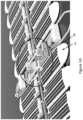
- the station keeping apparatus 20 may be a gravity-based mooring arrangement which includes anchor or spud legs 124, e.g. columns, pipes, attached to a gravity-based foundation 125, e.g. matted base attached to the legs 124 and/or spud can attach to each leg 124.
- the gravity-based foundation 125 is configured to be lowered, e.g. by ballasting, to the bottom of the body of water, e.g. sea bed, and may be secured thereto to secure the bottom portions of the legs.
- the aquaculture production apparatuses 10 may be mechanically coupled to the legs 124 such as by lines, e.g. mooring lines 122.
- Cross-braces or cables 126 may be arranged over the apparatuses 10 and couple the top portions of the legs to provide further stability to the mooring arrangement.
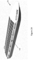
- a custodian transfer apparatus 30 is provided and configured to receive cultivated aquatic animals from various aquaculture production apparatuses 10 or farms, and transfer the aquatic animals through a chute 32 to an amalgamated facility 40.
- the custodian transfer apparatus 30 may be further configured to sort the aquatic animals and perform accounting, e.g. weighing and/or counting, of the aquatic animals before they enter the chute 32 and after they exit from the chute 32.
- the custodian transfer apparatus 30 includes at least one custodian chamber 31, a custodian transfer chute 32 and at least one custodian transfer pump.
- the custodian chamber 31 is configured to receive live aquatic animals from at least one aquaculture production apparatus 10.
- the custodian chamber 31 may include at least one inlet which is fluidly coupled to an aquaculture transfer pump 107b, and an outlet which is fluidly coupled to the chute 32.
- the custodian transfer apparatus 30, e.g. custodian chamber 31, may include a first sorting apparatus, e.g. fish sorter, which is configured to detect sizes and/or specie of the aquatic animals and, based on the detected sizes and/or specie, allow entry of qualified aquatic animals which meet predetermined requirement(s) to enter the chute and/or block unwanted aquatic animals which fall within one or more predetermined unwanted sizes and/or specie, e.g. pregnant fish, under-sized fish, from entering the chute 32.
- the first sorting apparatus may include a bypass gate configured to direct the unwanted aquatic animals to the originating cultivation tank 103 or other designated tanks.
- the custodian transfer apparatus 30, e.g. custodian chamber 31, may include a first counter apparatus which is configured to count the number of cultivated aquatic animals, e.g. sorted aquatic animals, before they enter the chute 32. It is to be appreciated that the first counter apparatus may be provided by or integrated with the first sorting apparatus.
- the custodian transfer apparatus 30 is provided as part of a vessel, e.g. barge, which may be mechanically coupled or moored to the station keeping apparatus 20.
- the barge may include storage space, e.g. for storing fish meal, energy generation plant, e.g. renewable and waste-to-energy plant, water treatment plant, and waste control / treatment.
- the custodian transfer apparatus 30 is configured to transfer live aquatic animals therefrom to an amalgamated facility 40, which is separated from the custodian transfer apparatus 30 and aquaculture production apparatuses 10 by a body of water, through a chute 32.
- the chute 32 may include a flexible hose or a rigid pipe or a combination thereof.
- the chute 32 includes at least one portion thereof which may be floating on water or submerged or arranged at the water bed / sea bed or combinations thereof.
- the chute 32 includes an inlet which is fluidly coupled to the outlet of the custodian transfer apparatus 30, e.g. custodian chamber 31, and an outlet which is located at or near the amalgamated facility 40.
- the custodian transfer pump(s) may be arranged at the inlet and/or outlet of the chute and configured to draw a flow of water through the chute 32 such that the aquatic animals are transported towards the outlet of the chute by the flow of water, e.g. induced water current.
- the custodian transfer apparatus 30 includes a fish or aquatic animal lift 34 arranged at the outlet of the chute and configured to vertically lift the aquatic animals leaving the chute to the amalgamated facility 40.
- a fish or aquatic animal lift include spiral shaped multi-level conveyor belt, Archimedes screw or screw pump.
- the fish lift 34 includes an inlet fluidly coupled to the outlet of the chute 32, and an outlet for discharging the aquatic animals.
- the custodian transfer apparatus 30 includes a second counter apparatus arranged at the outlet of the chute and configured to count a number of the aquatic animals leaving the chute.
- an offshore amalgamated facility 40 includes an inbound/import facility, a hatchery facility, a sorting facility, an aquaculture processing facility, an export facility, an agricultural facility, an infrastructure facility, an accommodation facility, and at least two berthing spaces.
- the inbound/import facility may include an arrival chamber for receiving aquatic animals exiting from the chute 32 and/or Archimedes screw.
- the inbound/import facility may be further configured to receive aquatic animals from other than the aquaculture production apparatus 10, e.g. from wild harvest.
- the hatchery facility may include nursery and/or research and development facilities.
- the sorting facility may include a second sorting apparatus, e.g. fish sorter, shaker apparatus, to sort aquatic animals into different weight, sizes and/or specie.
- a shaker apparatus produce vibrations which sort aquatic animals by their weight.
- pregnant female fish may be detected by their weight and/or size and transferred to a hatchery.
- the sorting facility may include an optical camera for ascertaining marketability of aquatic animals based on its attributes. For example, the optical camera detects specie and/or colour of fish, and based on the detected specie and/or colour, the fish is transferred to separate chambers.
- the aquaculture processing facility may include a factory for processing the aquatic animals into aquaculture products, e.g. filleting and freezing of fresh fish for export and onward distribution for human consumption, and recycling wastes from aquaculture processing into aquaculture by-products, e.g. fertilisers, fish meal.
- a factory for processing the aquatic animals into aquaculture products e.g. filleting and freezing of fresh fish for export and onward distribution for human consumption
- wastes from aquaculture processing into aquaculture by-products e.g. fertilisers, fish meal.
- the export facility is configured to allow loading of aquaculture products and/or by-products onto live fish carriers or other transport vessels.
- Examples include a berth for sea-going vessels, e.g. trawlers, cargo ships, and a helipad for helicopters.
- the vertical agricultural and/or agroculture facility may include farms which may utilize by-products - fertilizer from fish faeces and fish emulsifier produced from the aquaculture processing facility and/or aquaponics.
- the infrastructure facility includes housing structures for establishment, offices for local custom department, special equipment & machinery, , research and development & hatchery, etc.
- the accommodation facility includes housing structures for operation staff, visitors, and hotels for tourists, etc.
- At least one aquaculture production apparatus 10, station keeping apparatus 20, custodian transfer apparatus 30 and their components are provided and/or arranged as described in the foregoing description.
- aquatic animals are cultivated in the aquaculture production apparatus which is arranged in a body of water.
- This cultivation step may include providing a water production and/or circulation system in each aquaculture production apparatus 10.
- the water production and/or circulation system allows clean or fish production water, which is to be channeled to cultivation tanks 103, to be alternatively received from the body of water or the ballast water spaces.
- water to be channeled to cultivation tanks 103 is transferred from ballast water space 102 via the inlet channel 104a while water discharged from the cultivation tanks 103 is transferred, via the discharge channel 105b, to a waste water storage tank 116 arranged at/on the hull. Water in the waste water storage tank 116 is treated to produce treated water. The treated water is transferred to the ballast water spaces 102 for subsequent use as clean or fish production water.
- This cultivation step includes supplying the cultivation tanks with water at a flow rate similar to discharging the cultivation tanks of water.
- This cultivation step may further include discharging water from the cultivation tanks to a discharge channel, by siphonic drainage, through the plurality of tank discharge pipes which are fluidly coupled between the cultivation tanks and the discharge channel; and discharging water from the cultivation tanks to the discharge channel by an overflow from the cultivation tanks.
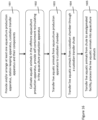
- aquatic animals are transferred from the floatable aquaculture production apparatus through one of the tank discharge pipes to a custodian transfer chamber.
- the aquatic animals are transported through an inlet and an outlet of the chute by drawing a flow of water through the chute, wherein the inlet of the chute is fluidly coupled to the custodian transfer chamber.
- the aquatic animals are vertically lifted from the outlet of the chute onto an amalgamated facility.
- the amalgamated facility 40 e.g. arrival chamber
- the live aquatic animals may be accounted, e.g. weighed, counted, and/or sorted, e.g. by size, weight, species.
- the aquatic animals may be processed in an aquaculture processing facility into aquaculture products before they are exported from the export facility to wholesalers, retailers and/or consumers. Unwanted aquatic animals or parts thereof may be processed into by-products and utilized as fertilizers for a vertical agriculture facility on the amalgamated facility 40.
Landscapes
- Life Sciences & Earth Sciences (AREA)
- Engineering & Computer Science (AREA)
- Environmental Sciences (AREA)
- Ocean & Marine Engineering (AREA)
- Chemical & Material Sciences (AREA)
- Combustion & Propulsion (AREA)
- Mechanical Engineering (AREA)
- Zoology (AREA)
- Marine Sciences & Fisheries (AREA)
- Animal Husbandry (AREA)
- Biodiversity & Conservation Biology (AREA)
- Structural Engineering (AREA)
- Civil Engineering (AREA)
- Architecture (AREA)
- Health & Medical Sciences (AREA)
- Environmental & Geological Engineering (AREA)
- General Health & Medical Sciences (AREA)
- Public Health (AREA)
- Toxicology (AREA)
- Farming Of Fish And Shellfish (AREA)
- Filling Or Discharging Of Gas Storage Vessels (AREA)
- Aiming, Guidance, Guns With A Light Source, Armor, Camouflage, And Targets (AREA)
Applications Claiming Priority (2)
| Application Number | Priority Date | Filing Date | Title |
|---|---|---|---|
| SG10201608768V | 2016-10-19 | ||
| PCT/SG2017/050494 WO2018074976A1 (en) | 2016-10-19 | 2017-10-02 | System and method for off-shore & in-shore aquaculture using floating closed containment farming and amalgamated facility |
Publications (3)
| Publication Number | Publication Date |
|---|---|
| EP3528621A1 EP3528621A1 (en) | 2019-08-28 |
| EP3528621A4 EP3528621A4 (en) | 2020-06-17 |
| EP3528621B1 true EP3528621B1 (en) | 2023-09-13 |
Family
ID=62018736
Family Applications (1)
| Application Number | Title | Priority Date | Filing Date |
|---|---|---|---|
| EP17863211.3A Active EP3528621B1 (en) | 2016-10-19 | 2017-10-02 | System and method for aquaculture using floating closed containment farming |
Country Status (10)
| Country | Link |
|---|---|
| US (1) | US11439131B2 (da) |
| EP (1) | EP3528621B1 (da) |
| CN (4) | CN110167343B (da) |
| AU (2) | AU2017347309B2 (da) |
| CA (1) | CA3062937A1 (da) |
| DK (1) | DK3528621T3 (da) |
| ES (1) | ES2962341T3 (da) |
| FI (1) | FI3528621T3 (da) |
| SG (4) | SG11201810478QA (da) |
| WO (2) | WO2018074976A1 (da) |
Families Citing this family (21)
| Publication number | Priority date | Publication date | Assignee | Title |
|---|---|---|---|---|
| CN110167343B (zh) * | 2016-10-19 | 2021-10-12 | 艾米海事环境能源私人有限公司 | 使用浮动封闭受控式养殖和合并设施进行离岸和靠岸水产养殖的系统和方法 |
| US10894710B1 (en) * | 2017-10-20 | 2021-01-19 | Garrett T. Johnson | Transportable service station |
| CA3107067A1 (en) | 2018-07-24 | 2020-01-30 | Running Tide Technologies, Inc. | System and method for the cultivation of aquatic animals |
| US11766030B2 (en) | 2018-08-06 | 2023-09-26 | Northeastern University | Robotic aquaculture system and methods |
| DE102019102223A1 (de) * | 2019-01-29 | 2020-07-30 | Hochschule Für Technik Und Wirtschaft Des Saarlandes | Wasserfahrzeug und Verfahren zur Produktion aquatischer Lebewesen |
| EP3909425B1 (en) * | 2019-03-14 | 2024-07-10 | Trotta, Paulo Ferreira | Device and method for cultivating oysters |
| US12414549B2 (en) * | 2019-08-09 | 2025-09-16 | Scallop Bay Shellfish Company, Llc | System and method for modular aquaculture |
| CN110542750B (zh) * | 2019-09-24 | 2022-04-08 | 重庆工商大学 | 水产养殖水质智能检测控制方法与系统 |
| NO345758B1 (no) | 2020-01-28 | 2021-07-12 | Hauge Aqua Solutions As | Forbedret oppdrettstank |
| WO2022098341A1 (en) * | 2020-11-09 | 2022-05-12 | Sf Yüzer Yapilar İnşaat Sanayi̇ Ve Ti̇caret Anoni̇m Şi̇rketi̇ | A floating waste water treatment facility for disposal of marine debris at source |
| NO346305B1 (no) | 2020-12-19 | 2022-05-30 | Hauge Aqua Solutions As | En flytende, hovedsakelig eggformet oppdrettstank med øvre, sugende pumpeutløp. |
| CN114857485A (zh) * | 2021-02-03 | 2022-08-05 | 中国石油天然气集团有限公司 | 组合式fsru设备 |
| CN113430988B (zh) * | 2021-07-01 | 2022-10-18 | 中国水利水电第五工程局有限公司 | 生态预制块及河道生态挡墙 |
| CN114506421B (zh) * | 2022-02-16 | 2023-09-26 | 广西柳工机械股份有限公司 | 一种水上定位调平设备 |
| US20250376246A1 (en) * | 2022-06-17 | 2025-12-11 | Twenty20 Energy Systems Pte Ltd | Lng storage barge with shallow draught |
| NO347596B1 (en) * | 2022-07-08 | 2024-01-22 | Bue Salmon As | Plant for aquaculture and outlet for aquaculture tanks |
| CN116098099A (zh) * | 2023-02-01 | 2023-05-12 | 云南省渔业科学研究院 | 一种土著鱼原位隔离繁殖装置 |
| NO349289B1 (en) * | 2023-06-07 | 2025-11-24 | Next Tuna Gmbh | Floating ras system, and use and method of operation thereof |
| NO349128B1 (en) * | 2024-02-29 | 2025-10-13 | Cflow As | Vessel and a method for transferring fish to and from said vessel |
| NO349209B1 (en) | 2024-06-21 | 2025-11-03 | Fred Olsen 1848 As | Method for installation of a vessel in a seabed |
| CN120323390B (zh) * | 2025-04-30 | 2025-12-09 | 阳江市水产技术推广站 | 大规格海水鱼苗工厂化分级培育系统 |
Family Cites Families (51)
| Publication number | Priority date | Publication date | Assignee | Title |
|---|---|---|---|---|
| NL7016406A (da) * | 1970-11-10 | 1972-05-15 | ||
| NO134458C (da) * | 1971-01-21 | 1976-10-13 | Prieto Gonzalo Alonso Lamberti | |
| US3797256A (en) * | 1972-09-08 | 1974-03-19 | Sharp Inc G | Jack-up type offshore platform apparatus |
| GB1491709A (en) * | 1974-08-08 | 1977-11-16 | Conch Int Methane Ltd | Thermally-insulated containers |
| CA1093401A (en) * | 1977-11-14 | 1981-01-13 | Rodolphe Streichenberger | Method and device for practicing marine aquaculture |
| SE440973B (sv) * | 1984-02-02 | 1985-09-02 | Trelleborg Ab | Anleggning for fiskodling i oppen sjo med flytkroppar ledbart forbundna med varandra och stabiliserade med en tyngdbelastad kjol anleggning for fiskodling i oppen sjo med flytkroppar ledbart forbundna med varandra och stabiliserade med en tyngdbelastad kjol |
| NO162692C (no) * | 1987-10-13 | 1990-02-07 | Kaare Espedalen | Fremgangsmaate og apparat for stoerrelsessortering av levende fisk. |
| US4930444A (en) * | 1988-09-26 | 1990-06-05 | Vasile Vincent R | Apparatus and method of fishing for swimming fish |
| CN1019654B (zh) * | 1988-10-25 | 1992-12-30 | 大阪湾开发管理株式会社 | 运货驳船 |
| SE466998B (sv) * | 1991-03-15 | 1992-05-11 | Christer Elander | System foer korrigering av ojaemn lastfoerdelning hos fartyg |
| JPH0824509B2 (ja) * | 1991-05-30 | 1996-03-13 | 海洋科学技術センター | 潜降浮上型海洋構造物 |
| FR2683786B1 (fr) * | 1991-11-20 | 1994-02-18 | Gaz Transport | Cuve etanche et thermiquement isolante perfectionnee, integree a la structure porteuse d'un navire. |
| US5438958A (en) * | 1993-11-18 | 1995-08-08 | Ericsson; John D. | Platform supported mariculture system |
| CA2120969A1 (en) * | 1994-04-11 | 1995-10-12 | John E. Huguenin | In situ marine fish incubator |
| WO1997002983A1 (en) * | 1995-07-13 | 1997-01-30 | Orca Marine Company Limited | Floating dock |
| CA2251965C (en) * | 1996-04-17 | 2007-07-10 | Merriam Research | Aquaculture system |
| US5762024A (en) * | 1996-04-17 | 1998-06-09 | David E. Meilahn | Aquaculture system |
| AU2636199A (en) * | 1998-02-19 | 1999-09-06 | Thomas Murphy | Fish farming |
| WO2002081297A2 (en) * | 2001-04-03 | 2002-10-17 | Metro Machine Corp. | Lng storage vessel and method for constructing same |
| CN2598860Y (zh) * | 2003-01-23 | 2004-01-14 | 陕西科技大学 | 船舶浮力储备装置 |
| AR051282A1 (es) * | 2005-08-31 | 2007-01-03 | Jorge Raul Abal | Una barcaza tanque para el transporte de liquido |
| US20100074692A1 (en) * | 2006-09-11 | 2010-03-25 | Mark E Ehrhardt | Open-Sea Berth LNG Import Terminal |
| CN100497080C (zh) * | 2007-07-06 | 2009-06-10 | 胡建东 | 气浮法蓝藻打捞船 |
| CN101544272A (zh) * | 2008-03-26 | 2009-09-30 | 吴植融 | 液体水下储存、装载和外卸装置 |
| KR100991994B1 (ko) * | 2008-03-28 | 2010-11-04 | 삼성중공업 주식회사 | 액화가스 로딩/언로딩 시스템을 가지는 액화천연가스운반선 |
| CN201280218Y (zh) * | 2008-05-08 | 2009-07-29 | 马田·贝 | 自牵引移动升船和移船的锚碇系统 |
| WO2009149519A1 (en) * | 2008-06-12 | 2009-12-17 | Winwick Business Solutions Pty Ltd | System for cultivation and processing of microorganisms and products therefrom |
| US8312828B2 (en) * | 2009-01-26 | 2012-11-20 | Technip France | Preloading to reduce loads and save steel on topsides and grillage of catamaran systems |
| GB2482798B (en) * | 2009-03-03 | 2013-10-09 | Agrimarine Ind Inc | Solid wall closed containment aquaculture system |
| ES2361863B1 (es) * | 2009-12-11 | 2012-05-09 | Grupo De Ingenieria Oceanica S.L. | Sistema universal de puesta a flote y botadura y método de funcionamiento. |
| CN101746488B (zh) * | 2010-01-11 | 2012-08-22 | 程中和 | 水上清道夫多功能环保船设备及其方法 |
| NO332244B1 (no) * | 2010-03-30 | 2012-08-06 | Fredrik Mood | Oppdrettsanlegg omfattende ombygde tank- og bulkskip samt anvendelse derav |
| FI121876B (fi) * | 2010-04-09 | 2011-05-31 | Waertsilae Finland Oy | Menetelmä LNG:tä polttoaineenaan käyttävän vesialuksen käyttämiseksi ja vastaava vesialus |
| GB201010938D0 (en) * | 2010-06-29 | 2010-08-11 | Fugro Seacore Ltd | Self elevating platforms |
| CN102939917B (zh) * | 2012-10-19 | 2014-12-10 | 中国水产科学研究院渔业机械仪器研究所 | 一种船载海洋养殖系统 |
| CN102935880B (zh) * | 2012-11-26 | 2015-07-15 | 山东大学 | 可移动新能源海上产业公共平台 |
| KR101466888B1 (ko) * | 2013-04-03 | 2014-12-01 | 현대중공업 주식회사 | 반잠수식 중량물 운반선의 부력 케이싱 이동방법 |
| CN203332375U (zh) * | 2013-07-15 | 2013-12-11 | 周昊 | 一种新概念可分离式深潜器 |
| KR101549695B1 (ko) * | 2013-08-29 | 2015-09-03 | 배연숙 | 양식장 용존산소 증가장치 |
| KR102055401B1 (ko) * | 2013-09-03 | 2019-12-12 | 대우조선해양 주식회사 | 세미 리그선의 가설 발라스트 장치 |
| WO2015173838A1 (en) * | 2014-05-12 | 2015-11-19 | Vaki Fiskeldiskerfi Hf. | Optical system for counting objects |
| CN103988802B (zh) * | 2014-06-05 | 2016-08-17 | 中国水产科学研究院渔业机械仪器研究所 | 一种网箱养殖自动投饲平台系统及操作方法 |
| NO337233B1 (no) * | 2014-11-07 | 2016-02-15 | Macgregor Pusnes As | Et system og fremgangsmåte for å håndtere store og tunge konstruksjoner fra et offshore installasjonsfartøy |
| AU2014412083B2 (en) * | 2014-11-18 | 2019-01-03 | Keppel Offshore & Marine Technology Centre Pte Ltd | A submersible vessel for dry docking a vessel |
| AU2015203127C1 (en) * | 2015-05-28 | 2016-08-04 | Woodside Energy Technologies Pty Ltd | An lng production plant and a method for installation of an lng production plant |
| NO341376B1 (no) * | 2016-03-02 | 2017-10-23 | Akvadesign As | Oppdriftssystem for en merd |
| CN105900865B (zh) * | 2016-04-14 | 2019-01-04 | 威海白云渔业有限公司 | 立体生态养殖人工鱼礁 |
| CN110167343B (zh) * | 2016-10-19 | 2021-10-12 | 艾米海事环境能源私人有限公司 | 使用浮动封闭受控式养殖和合并设施进行离岸和靠岸水产养殖的系统和方法 |
| CN206866372U (zh) * | 2017-05-10 | 2018-01-12 | 广西南洋船舶工程有限公司 | 一种拼装式可移动水上浮动鱼苗培育养殖平台 |
| CN206808435U (zh) * | 2017-05-27 | 2017-12-29 | 上海神舟电力有限公司 | 一种水上漂浮式光伏发电与网箱养殖一体化装置 |
| CA3107067A1 (en) * | 2018-07-24 | 2020-01-30 | Running Tide Technologies, Inc. | System and method for the cultivation of aquatic animals |
-
2017
- 2017-10-02 CN CN201780059859.1A patent/CN110167343B/zh active Active
- 2017-10-02 FI FIEP17863211.3T patent/FI3528621T3/fi active
- 2017-10-02 WO PCT/SG2017/050494 patent/WO2018074976A1/en not_active Ceased
- 2017-10-02 CA CA3062937A patent/CA3062937A1/en active Pending
- 2017-10-02 CN CN202111175560.7A patent/CN113841645B/zh active Active
- 2017-10-02 SG SG11201810478QA patent/SG11201810478QA/en unknown
- 2017-10-02 EP EP17863211.3A patent/EP3528621B1/en active Active
- 2017-10-02 SG SG10201907721UA patent/SG10201907721UA/en unknown
- 2017-10-02 ES ES17863211T patent/ES2962341T3/es active Active
- 2017-10-02 US US16/340,624 patent/US11439131B2/en active Active
- 2017-10-02 DK DK17863211.3T patent/DK3528621T3/da active
- 2017-10-02 AU AU2017347309A patent/AU2017347309B2/en active Active
- 2017-10-17 SG SG10202103429RA patent/SG10202103429RA/en unknown
- 2017-10-17 WO PCT/SG2017/050521 patent/WO2018074977A1/en not_active Ceased
- 2017-10-17 CN CN202210368958.0A patent/CN114684330A/zh active Pending
- 2017-10-17 CN CN201780065033.6A patent/CN109952246B/zh active Active
- 2017-10-17 SG SG11201902936XA patent/SG11201902936XA/en unknown
-
2019
- 2019-12-18 AU AU2019283874A patent/AU2019283874B2/en active Active
Also Published As
| Publication number | Publication date |
|---|---|
| ES2962341T3 (es) | 2024-03-18 |
| CN110167343B (zh) | 2021-10-12 |
| SG11201810478QA (en) | 2018-12-28 |
| CN109952246B (zh) | 2022-04-08 |
| AU2017347309A1 (en) | 2019-02-07 |
| AU2019283874B2 (en) | 2021-08-05 |
| SG11201902936XA (en) | 2019-05-30 |
| EP3528621A4 (en) | 2020-06-17 |
| SG10202103429RA (en) | 2021-05-28 |
| SG10201907721UA (en) | 2019-09-27 |
| CA3062937A1 (en) | 2018-04-26 |
| AU2019283874A1 (en) | 2020-01-23 |
| WO2018074977A1 (en) | 2018-04-26 |
| CN113841645A (zh) | 2021-12-28 |
| NZ759050A (en) | 2024-03-22 |
| DK3528621T3 (da) | 2023-10-16 |
| FI3528621T3 (fi) | 2023-10-20 |
| CN109952246A (zh) | 2019-06-28 |
| WO2018074976A1 (en) | 2018-04-26 |
| CN113841645B (zh) | 2023-10-10 |
| CN110167343A (zh) | 2019-08-23 |
| EP3528621A1 (en) | 2019-08-28 |
| CN114684330A (zh) | 2022-07-01 |
| AU2017347309B2 (en) | 2019-10-03 |
| US20190274289A1 (en) | 2019-09-12 |
| US11439131B2 (en) | 2022-09-13 |
Similar Documents
| Publication | Publication Date | Title |
|---|---|---|
| AU2019283874B2 (en) | System and method for off-shore and in-shore aquaculture using floating closed containment farming and amalgamated facility | |
| CN109757415B (zh) | 大型深远海工船网箱一体化的渔业生产平台及其作业方法 | |
| US8371245B2 (en) | Aquaculture production system | |
| EP4454459A1 (en) | Fish farming system | |
| CN102939918B (zh) | 一种海洋渔业生产平台 | |
| CN209995142U (zh) | 大型深远海工船网箱一体化的渔业生产平台 | |
| NO341817B1 (en) | Semi-submersible fish farming system | |
| CN115088661B (zh) | 海上养殖平台 | |
| CN110140683A (zh) | 一种多层次养殖海洋渔场 | |
| NO20190905A1 (en) | Fish farm | |
| WO2023167596A1 (en) | Fish farming systems | |
| WO2020180192A1 (en) | Fish farm installation | |
| HK40062755A (en) | Aquaculture production apparatus, aquaculture transfer system and method | |
| WO2003067971A1 (en) | Device for farming of marine organisms, particularly fish | |
| HK40062755B (zh) | 水产养殖生产设备、水产养殖生产和输送系统以及方法 | |
| Wang et al. | Recent developments in offshore fish pens | |
| ES2221784B1 (es) | Piscifactoria navegable perfeccionada. | |
| HK40013417A (en) | System and method for off-shore & in-shore aquaculture using floating closed containment farming and amalgamated facility | |
| HK40013417B (en) | System and method for off-shore & in-shore aquaculture using floating closed containment farming and amalgamated facility | |
| Wang et al. | Recent Developments in Offshore Fish | |
| JP2004173534A (ja) | 浮体構造物内部における魚介類の養殖・蓄養方法 | |
| PH12017050067A1 (en) | Fish pen |
Legal Events
| Date | Code | Title | Description |
|---|---|---|---|
| STAA | Information on the status of an ep patent application or granted ep patent |
Free format text: STATUS: THE INTERNATIONAL PUBLICATION HAS BEEN MADE |
|
| PUAI | Public reference made under article 153(3) epc to a published international application that has entered the european phase |
Free format text: ORIGINAL CODE: 0009012 |
|
| STAA | Information on the status of an ep patent application or granted ep patent |
Free format text: STATUS: REQUEST FOR EXAMINATION WAS MADE |
|
| 17P | Request for examination filed |
Effective date: 20190221 |
|
| AK | Designated contracting states |
Kind code of ref document: A1 Designated state(s): AL AT BE BG CH CY CZ DE DK EE ES FI FR GB GR HR HU IE IS IT LI LT LU LV MC MK MT NL NO PL PT RO RS SE SI SK SM TR |
|
| AX | Request for extension of the european patent |
Extension state: BA ME |
|
| DAV | Request for validation of the european patent (deleted) | ||
| DAX | Request for extension of the european patent (deleted) | ||
| A4 | Supplementary search report drawn up and despatched |
Effective date: 20200518 |
|
| RIC1 | Information provided on ipc code assigned before grant |
Ipc: A01K 61/60 20170101AFI20200512BHEP |
|
| REG | Reference to a national code |
Ref country code: HK Ref legal event code: DE Ref document number: 40013416 Country of ref document: HK |
|
| GRAP | Despatch of communication of intention to grant a patent |
Free format text: ORIGINAL CODE: EPIDOSNIGR1 |
|
| STAA | Information on the status of an ep patent application or granted ep patent |
Free format text: STATUS: GRANT OF PATENT IS INTENDED |
|
| INTG | Intention to grant announced |
Effective date: 20230411 |
|
| GRAS | Grant fee paid |
Free format text: ORIGINAL CODE: EPIDOSNIGR3 |
|
| GRAA | (expected) grant |
Free format text: ORIGINAL CODE: 0009210 |
|
| STAA | Information on the status of an ep patent application or granted ep patent |
Free format text: STATUS: THE PATENT HAS BEEN GRANTED |
|
| RAP3 | Party data changed (applicant data changed or rights of an application transferred) |
Owner name: AME2 PTE LTD |
|
| AK | Designated contracting states |
Kind code of ref document: B1 Designated state(s): AL AT BE BG CH CY CZ DE DK EE ES FI FR GB GR HR HU IE IS IT LI LT LU LV MC MK MT NL NO PL PT RO RS SE SI SK SM TR |
|
| REG | Reference to a national code |
Ref country code: GB Ref legal event code: FG4D |
|
| REG | Reference to a national code |
Ref country code: CH Ref legal event code: EP |
|
| REG | Reference to a national code |
Ref country code: DE Ref legal event code: R096 Ref document number: 602017074273 Country of ref document: DE |
|
| REG | Reference to a national code |
Ref country code: IE Ref legal event code: FG4D |
|
| REG | Reference to a national code |
Ref country code: DK Ref legal event code: T3 Effective date: 20231013 |
|
| REG | Reference to a national code |
Ref country code: FI Ref legal event code: FGE |
|
| REG | Reference to a national code |
Ref country code: NO Ref legal event code: T2 Effective date: 20230913 |
|
| REG | Reference to a national code |
Ref country code: SE Ref legal event code: TRGR |
|
| REG | Reference to a national code |
Ref country code: GR Ref legal event code: EP Ref document number: 20230402241 Country of ref document: GR Effective date: 20231211 |
|
| REG | Reference to a national code |
Ref country code: LT Ref legal event code: MG9D |
|
| REG | Reference to a national code |
Ref country code: NL Ref legal event code: MP Effective date: 20230913 |
|
| PG25 | Lapsed in a contracting state [announced via postgrant information from national office to epo] |
Ref country code: RS Free format text: LAPSE BECAUSE OF FAILURE TO SUBMIT A TRANSLATION OF THE DESCRIPTION OR TO PAY THE FEE WITHIN THE PRESCRIBED TIME-LIMIT Effective date: 20230913 Ref country code: LV Free format text: LAPSE BECAUSE OF FAILURE TO SUBMIT A TRANSLATION OF THE DESCRIPTION OR TO PAY THE FEE WITHIN THE PRESCRIBED TIME-LIMIT Effective date: 20230913 Ref country code: LT Free format text: LAPSE BECAUSE OF FAILURE TO SUBMIT A TRANSLATION OF THE DESCRIPTION OR TO PAY THE FEE WITHIN THE PRESCRIBED TIME-LIMIT Effective date: 20230913 Ref country code: HR Free format text: LAPSE BECAUSE OF FAILURE TO SUBMIT A TRANSLATION OF THE DESCRIPTION OR TO PAY THE FEE WITHIN THE PRESCRIBED TIME-LIMIT Effective date: 20230913 |
|
| REG | Reference to a national code |
Ref country code: AT Ref legal event code: MK05 Ref document number: 1610329 Country of ref document: AT Kind code of ref document: T Effective date: 20230913 |
|
| PG25 | Lapsed in a contracting state [announced via postgrant information from national office to epo] |
Ref country code: NL Free format text: LAPSE BECAUSE OF FAILURE TO SUBMIT A TRANSLATION OF THE DESCRIPTION OR TO PAY THE FEE WITHIN THE PRESCRIBED TIME-LIMIT Effective date: 20230913 |
|
| REG | Reference to a national code |
Ref country code: ES Ref legal event code: FG2A Ref document number: 2962341 Country of ref document: ES Kind code of ref document: T3 Effective date: 20240318 |
|
| PG25 | Lapsed in a contracting state [announced via postgrant information from national office to epo] |
Ref country code: IS Free format text: LAPSE BECAUSE OF FAILURE TO SUBMIT A TRANSLATION OF THE DESCRIPTION OR TO PAY THE FEE WITHIN THE PRESCRIBED TIME-LIMIT Effective date: 20240113 |
|
| PG25 | Lapsed in a contracting state [announced via postgrant information from national office to epo] |
Ref country code: AT Free format text: LAPSE BECAUSE OF FAILURE TO SUBMIT A TRANSLATION OF THE DESCRIPTION OR TO PAY THE FEE WITHIN THE PRESCRIBED TIME-LIMIT Effective date: 20230913 |
|
| PG25 | Lapsed in a contracting state [announced via postgrant information from national office to epo] |
Ref country code: SM Free format text: LAPSE BECAUSE OF FAILURE TO SUBMIT A TRANSLATION OF THE DESCRIPTION OR TO PAY THE FEE WITHIN THE PRESCRIBED TIME-LIMIT Effective date: 20230913 Ref country code: RO Free format text: LAPSE BECAUSE OF FAILURE TO SUBMIT A TRANSLATION OF THE DESCRIPTION OR TO PAY THE FEE WITHIN THE PRESCRIBED TIME-LIMIT Effective date: 20230913 Ref country code: IS Free format text: LAPSE BECAUSE OF FAILURE TO SUBMIT A TRANSLATION OF THE DESCRIPTION OR TO PAY THE FEE WITHIN THE PRESCRIBED TIME-LIMIT Effective date: 20240113 Ref country code: EE Free format text: LAPSE BECAUSE OF FAILURE TO SUBMIT A TRANSLATION OF THE DESCRIPTION OR TO PAY THE FEE WITHIN THE PRESCRIBED TIME-LIMIT Effective date: 20230913 Ref country code: CZ Free format text: LAPSE BECAUSE OF FAILURE TO SUBMIT A TRANSLATION OF THE DESCRIPTION OR TO PAY THE FEE WITHIN THE PRESCRIBED TIME-LIMIT Effective date: 20230913 Ref country code: AT Free format text: LAPSE BECAUSE OF FAILURE TO SUBMIT A TRANSLATION OF THE DESCRIPTION OR TO PAY THE FEE WITHIN THE PRESCRIBED TIME-LIMIT Effective date: 20230913 Ref country code: SK Free format text: LAPSE BECAUSE OF FAILURE TO SUBMIT A TRANSLATION OF THE DESCRIPTION OR TO PAY THE FEE WITHIN THE PRESCRIBED TIME-LIMIT Effective date: 20230913 Ref country code: PT Free format text: LAPSE BECAUSE OF FAILURE TO SUBMIT A TRANSLATION OF THE DESCRIPTION OR TO PAY THE FEE WITHIN THE PRESCRIBED TIME-LIMIT Effective date: 20240115 |
|
| REG | Reference to a national code |
Ref country code: DE Ref legal event code: R119 Ref document number: 602017074273 Country of ref document: DE |
|
| PG25 | Lapsed in a contracting state [announced via postgrant information from national office to epo] |
Ref country code: PL Free format text: LAPSE BECAUSE OF FAILURE TO SUBMIT A TRANSLATION OF THE DESCRIPTION OR TO PAY THE FEE WITHIN THE PRESCRIBED TIME-LIMIT Effective date: 20230913 |
|
| REG | Reference to a national code |
Ref country code: CH Ref legal event code: PL |
|
| REG | Reference to a national code |
Ref country code: BE Ref legal event code: MM Effective date: 20231031 |
|
| PG25 | Lapsed in a contracting state [announced via postgrant information from national office to epo] |
Ref country code: LU Free format text: LAPSE BECAUSE OF NON-PAYMENT OF DUE FEES Effective date: 20231002 |
|
| PG25 | Lapsed in a contracting state [announced via postgrant information from national office to epo] |
Ref country code: LU Free format text: LAPSE BECAUSE OF NON-PAYMENT OF DUE FEES Effective date: 20231002 |
|
| PG25 | Lapsed in a contracting state [announced via postgrant information from national office to epo] |
Ref country code: MC Free format text: LAPSE BECAUSE OF FAILURE TO SUBMIT A TRANSLATION OF THE DESCRIPTION OR TO PAY THE FEE WITHIN THE PRESCRIBED TIME-LIMIT Effective date: 20230913 |
|
| PG25 | Lapsed in a contracting state [announced via postgrant information from national office to epo] |
Ref country code: CH Free format text: LAPSE BECAUSE OF NON-PAYMENT OF DUE FEES Effective date: 20231031 |
|
| PLBE | No opposition filed within time limit |
Free format text: ORIGINAL CODE: 0009261 |
|
| STAA | Information on the status of an ep patent application or granted ep patent |
Free format text: STATUS: NO OPPOSITION FILED WITHIN TIME LIMIT |
|
| PG25 | Lapsed in a contracting state [announced via postgrant information from national office to epo] |
Ref country code: MC Free format text: LAPSE BECAUSE OF FAILURE TO SUBMIT A TRANSLATION OF THE DESCRIPTION OR TO PAY THE FEE WITHIN THE PRESCRIBED TIME-LIMIT Effective date: 20230913 Ref country code: DE Free format text: LAPSE BECAUSE OF NON-PAYMENT OF DUE FEES Effective date: 20240501 Ref country code: CH Free format text: LAPSE BECAUSE OF NON-PAYMENT OF DUE FEES Effective date: 20231031 |
|
| 26N | No opposition filed |
Effective date: 20240614 |
|
| PG25 | Lapsed in a contracting state [announced via postgrant information from national office to epo] |
Ref country code: BE Free format text: LAPSE BECAUSE OF NON-PAYMENT OF DUE FEES Effective date: 20231031 |
|
| PG25 | Lapsed in a contracting state [announced via postgrant information from national office to epo] |
Ref country code: SI Free format text: LAPSE BECAUSE OF FAILURE TO SUBMIT A TRANSLATION OF THE DESCRIPTION OR TO PAY THE FEE WITHIN THE PRESCRIBED TIME-LIMIT Effective date: 20230913 |
|
| PG25 | Lapsed in a contracting state [announced via postgrant information from national office to epo] |
Ref country code: SI Free format text: LAPSE BECAUSE OF FAILURE TO SUBMIT A TRANSLATION OF THE DESCRIPTION OR TO PAY THE FEE WITHIN THE PRESCRIBED TIME-LIMIT Effective date: 20230913 |
|
| PG25 | Lapsed in a contracting state [announced via postgrant information from national office to epo] |
Ref country code: BG Free format text: LAPSE BECAUSE OF FAILURE TO SUBMIT A TRANSLATION OF THE DESCRIPTION OR TO PAY THE FEE WITHIN THE PRESCRIBED TIME-LIMIT Effective date: 20230913 |
|
| PG25 | Lapsed in a contracting state [announced via postgrant information from national office to epo] |
Ref country code: BG Free format text: LAPSE BECAUSE OF FAILURE TO SUBMIT A TRANSLATION OF THE DESCRIPTION OR TO PAY THE FEE WITHIN THE PRESCRIBED TIME-LIMIT Effective date: 20230913 |
|
| PGFP | Annual fee paid to national office [announced via postgrant information from national office to epo] |
Ref country code: GR Payment date: 20241007 Year of fee payment: 8 Ref country code: FI Payment date: 20241014 Year of fee payment: 8 |
|
| PGFP | Annual fee paid to national office [announced via postgrant information from national office to epo] |
Ref country code: IE Payment date: 20241015 Year of fee payment: 8 |
|
| PGFP | Annual fee paid to national office [announced via postgrant information from national office to epo] |
Ref country code: SE Payment date: 20241015 Year of fee payment: 8 |
|
| PG25 | Lapsed in a contracting state [announced via postgrant information from national office to epo] |
Ref country code: CY Free format text: LAPSE BECAUSE OF FAILURE TO SUBMIT A TRANSLATION OF THE DESCRIPTION OR TO PAY THE FEE WITHIN THE PRESCRIBED TIME-LIMIT; INVALID AB INITIO Effective date: 20171002 |
|
| PG25 | Lapsed in a contracting state [announced via postgrant information from national office to epo] |
Ref country code: HU Free format text: LAPSE BECAUSE OF FAILURE TO SUBMIT A TRANSLATION OF THE DESCRIPTION OR TO PAY THE FEE WITHIN THE PRESCRIBED TIME-LIMIT; INVALID AB INITIO Effective date: 20171002 |
|
| PGFP | Annual fee paid to national office [announced via postgrant information from national office to epo] |
Ref country code: TR Payment date: 20250925 Year of fee payment: 9 |
|
| PGFP | Annual fee paid to national office [announced via postgrant information from national office to epo] |
Ref country code: GB Payment date: 20251030 Year of fee payment: 9 |
|
| PGFP | Annual fee paid to national office [announced via postgrant information from national office to epo] |
Ref country code: NO Payment date: 20251030 Year of fee payment: 9 |
|
| PGFP | Annual fee paid to national office [announced via postgrant information from national office to epo] |
Ref country code: DK Payment date: 20251029 Year of fee payment: 9 Ref country code: IT Payment date: 20251028 Year of fee payment: 9 |
|
| PGFP | Annual fee paid to national office [announced via postgrant information from national office to epo] |
Ref country code: FR Payment date: 20251028 Year of fee payment: 9 |
|
| PGFP | Annual fee paid to national office [announced via postgrant information from national office to epo] |
Ref country code: ES Payment date: 20251201 Year of fee payment: 9 |
|
| REG | Reference to a national code |
Ref country code: HK Ref legal event code: WD Ref document number: 40013416 Country of ref document: HK |