EP3528665B1 - Meuble de relaxation - Google Patents
Meuble de relaxation Download PDFInfo
- Publication number
- EP3528665B1 EP3528665B1 EP17784526.0A EP17784526A EP3528665B1 EP 3528665 B1 EP3528665 B1 EP 3528665B1 EP 17784526 A EP17784526 A EP 17784526A EP 3528665 B1 EP3528665 B1 EP 3528665B1
- Authority
- EP
- European Patent Office
- Prior art keywords
- reclining surface
- lying
- recliner
- deflection
- lying surface
- Prior art date
- Legal status (The legal status is an assumption and is not a legal conclusion. Google has not performed a legal analysis and makes no representation as to the accuracy of the status listed.)
- Active
Links
Images



Classifications
-
- A—HUMAN NECESSITIES
- A47—FURNITURE; DOMESTIC ARTICLES OR APPLIANCES; COFFEE MILLS; SPICE MILLS; SUCTION CLEANERS IN GENERAL
- A47C—CHAIRS; SOFAS; BEDS
- A47C1/00—Chairs adapted for special purposes
- A47C1/14—Beach chairs ; Chairs for outdoor use, e.g. chairs for relaxation or sun-tanning
- A47C1/143—Chaise lounges
-
- A—HUMAN NECESSITIES
- A47—FURNITURE; DOMESTIC ARTICLES OR APPLIANCES; COFFEE MILLS; SPICE MILLS; SUCTION CLEANERS IN GENERAL
- A47C—CHAIRS; SOFAS; BEDS
- A47C3/00—Chairs characterised by structural features; Chairs or stools with rotatable or vertically-adjustable seats
- A47C3/02—Rocking chairs
- A47C3/021—Rocking chairs having elastic frames
-
- A—HUMAN NECESSITIES
- A61—MEDICAL OR VETERINARY SCIENCE; HYGIENE
- A61H—PHYSICAL THERAPY APPARATUS, e.g. DEVICES FOR LOCATING OR STIMULATING REFLEX POINTS IN THE BODY; ARTIFICIAL RESPIRATION; MASSAGE; BATHING DEVICES FOR SPECIAL THERAPEUTIC OR HYGIENIC PURPOSES OR SPECIFIC PARTS OF THE BODY
- A61H1/00—Apparatus for passive exercising; Vibrating apparatus; Chiropractic devices, e.g. body impacting devices, external devices for briefly extending or aligning unbroken bones
- A61H1/005—Moveable platforms, e.g. vibrating or oscillating platforms for standing, sitting, laying or leaning
-
- A—HUMAN NECESSITIES
- A61—MEDICAL OR VETERINARY SCIENCE; HYGIENE
- A61H—PHYSICAL THERAPY APPARATUS, e.g. DEVICES FOR LOCATING OR STIMULATING REFLEX POINTS IN THE BODY; ARTIFICIAL RESPIRATION; MASSAGE; BATHING DEVICES FOR SPECIAL THERAPEUTIC OR HYGIENIC PURPOSES OR SPECIFIC PARTS OF THE BODY
- A61H23/00—Percussion or vibration massage, e.g. using supersonic vibration; Suction-vibration massage; Massage with moving diaphragms
Definitions
- the present invention relates to reclining furniture according to the preamble of patent claim 1.
- reclining furniture is known from the prior art, in which the spring element has spring legs bent in a C-shape.
- Such recliner furniture are also known as cantilever chairs.
- the US 2011/0260507 A1 shows a generic reclining furniture, which is specially designed for babies.
- the lying surface is supported on a base by means of a coil spring.
- the coil spring is located in a housing which limits the maximum deflection of the coil spring in an adjustable manner.
- Other generic loungers are in the US 5,615,428 A and in the US 6,574,806 B1 shown.
- the FR 1 300 265 and the WO 2014/134467 A1 show sprung seating.
- the object of the invention is to improve a piece of reclining furniture of the type mentioned above in such a way that it better promotes the sleeping and / or resting process of the person lying on the lying surface.
- the invention proposes a reclining furniture according to claim 1.
- the invention provides that an additional limiting element keeps the spring element carrying the lying surface in an elastically prestressed state even in the unloaded state. This enables the lying surface to vibrate at a lower frequency than in the prior art when a person lies down on the lying surface. This promotes both sleeping and sleeping through the person lying on the lying surface or can at least have a relaxing effect on them.
- the reclining furniture can have one or more feet.
- the pedestal or pedestals are the components of the reclining furniture that lie directly on the surface on which the reclining furniture is placed in the normal operating position. In the case of several feet, these are preferably arranged in one plane.
- the substructure can in principle be designed very differently in the case of loungers according to the invention.
- the substructure supports the lying surface and for this purpose has at least one base and at least one elastic spring element arranged between the base and the lying surface.
- the limiting element is also preferably a component of the substructure that is additional to the spring element.
- the limiting element can be designed, for example, as a belt or loop be.
- the unloaded state is the state in which the substructure only bears the weight of the reclining furniture. In the unloaded state, there is neither a person nor any other load on the lying surface.
- the lying surface is the component of the lying furniture on which the person lies down.
- the support surface that is to say the surface of the lying surface on which the person ultimately lies, can also be designed to be curved. It is preferably provided, for example, that the support surface of the lying surface has a depression for the buttocks area and an increase as a backrest and an increase as a knee pad.
- the lying surface or the support surface can be curved, for example, approximately S-shaped or the like.
- the limiting element advantageously limits the deflection of the lying surface in the unloaded state in the direction away from the base.
- the reclining furniture can also have a stop element for limiting a deflection of the lying surface in the direction of the base in the loaded state.
- the loaded state is a state in which an additional mass, such as a person using the reclining furniture, lies on the lying surface.
- the elastic prestressing of the spring element according to the invention means that the spring element in the loaded state is still suitable, on the one hand, for carrying correspondingly large additional masses, such as correspondingly heavy people, and, on the other hand, can vibrate in this state at a relatively low frequency. This ensures low-frequency swinging that has a particularly sleep-promoting and relaxing effect on the reclining furniture. It is particularly preferred in the case of reclining furniture according to the invention that the lying surface is arranged in the unloaded state in a starting position and in a loaded state with an additional mass lying on the lying surface, preferably of 85 kg, in an intermediate position deflected relative to the starting position.
- the spring element is thus advantageously designed so that the intermediate position is reached after placing the additional mass on the lying surface.
- the lying surface in the loaded state around the deflected intermediate position can swing freely.
- the fact that the lying surface can swing freely around the deflected intermediate position in the loaded state means that the lying surface swings out in the form of a free damped vibration after a single deflection in the loaded state.
- the spring element is expediently designed such that the vibration from the intermediate position without additional drives is only excited by the person lying on the lying surface. It is particularly preferably provided that only the breathing of the person is sufficient to excite the vibration of the lying surface together with the additional mass lying on it in the form of a person.
- the pretension according to the invention which is held by the limiting element in the unloaded state, has the advantage that the intermediate position can be reached from the starting position with a relatively short spring deflection of the spring element and the desired vibration is then possible. Without prestressing, a very wide or strong deflection into the intermediate position would have to be accepted in order to then be able to carry out the desired vibrations. This would lead to a very shaky, difficult to control construction, which is prevented by the bias according to the invention.
- the reclining surface with an additional mass of 85 kg lying on the reclining surface after a single deflection from a rest position towards the base with a free vibration following the deflection has an oscillation frequency between 0.1 and 1 Hertz. Since the free oscillation after a single deflection is a so-called natural oscillation of the system consisting of reclining furniture and additional mass, one could also speak of the natural frequency as the oscillation frequency. In the rest position from which the deflection for excitation of the subsequent free oscillation takes place, one could also speak of the intermediate position in the preferred exemplary embodiments mentioned above. The ratio of inertia and spring stiffness is decisive for the vibration frequency.
- the spring element has a relatively low vibration damping.
- preferred variants of reclining furniture according to the invention provide that the reclining surface with an additional mass of 85 kg lying on the reclining surface after a single deflection from a rest position in the direction of the base with a free oscillation following the deflection has an amplitude maintenance greater than or equal to 20% , wherein the amplitude maintenance is calculated from the ratio of an amplitude of the sixth oscillation period after deflection to an amplitude of the second oscillation period after deflection.
- after deflection means that the oscillation periods are counted from the beginning of the free oscillation. While the first oscillation period is usually still strongly influenced by the deflection or the oscillation excitation, the second oscillation period is usually already that of a free damped oscillation.
- the pretension and also the other elastic properties of the spring element are advantageously chosen in such a way that it is ensured that neither the limiting element nor the stop element which may be present disturb this free oscillation.
- the spring element of the reclining furniture according to the invention can be designed very differently.
- Preferred variants provide that the at least one spring element has two spring legs which are connected to one another in a connection area.
- the spring legs can be arranged to diverge at least in regions, starting from the connection region.
- the legs are particularly preferably arranged one above the other in the operating position of the reclining furniture. It is possible, for example, for the stand (s) to be arranged on the lower spring leg, while the lying surface is on the bed, either directly or with the interposition of the adjustment device mentioned further below the upper spring leg of the spring element rests.
- the two spring legs can, but do not have to be integrally connected to one another in the connection area.
- the connection area can, for example, be C-shaped.
- the connecting area is advantageously arranged under or next to the half of the lying surface facing the foot end.
- the spring legs then advantageously diverge at least in regions in the direction towards the head end of the lying surface.
- the substructure of the reclining furniture according to the invention can have exactly one spring element but also several spring elements. Particularly preferred variants of the invention provide that the substructure has exactly two spring elements. These can be arranged at a distance from one another on opposite sides of the lying surface. Each of these spring elements can be designed in accordance with the preferred embodiment variants mentioned above.
- the lying furniture has an adjusting device for adjusting the lying surface relative to the spring element in mutually opposite longitudinal directions of the lying surface.
- This adjustment device makes it possible to reach the intermediate position and also to set the oscillation frequency of vibrations of the lying surface in the loaded state for different additional masses or persons of different weights, that is to say also those that deviate from 85 kg. In this way, the desired oscillation frequency can also be set for people of different weights, that is to say additional masses lying on the lying surface.
- the adjustment device is therefore a possibility of adapting the function to the weight of the person lying on the lying surface.
- the adjustment of the lying surface by means of the adjustment device does not necessarily have to take place in exactly horizontal, opposite longitudinal directions of the lying surface.
- the longitudinal directions in which the adjustment device can adjust the lying surface relative to the spring element advantageously have at least one horizontal component in the operating position.
- the Adjustment device is advantageously designed to be lockable.
- the adjusting device enables the lying surface to be adjusted relative to the spring element, but on the other hand also allows the respectively set position to be locked.
- the adjusting device is designed to be self-locking or self-locking, that is to hold the position that has been set on its own without an additional measure having to be taken.
- the adjusting device is advantageously arranged between the substructure and the lying surface, preferably between the spring element and the lying surface.
- the adjustment device is advantageously designed to be free of play. When locked, it should guarantee a quasi-rigid connection between the lying surface and the substructure.
- the adjustment device can be designed differently. E.g. it can be a kind of sledge.
- the adjustment device can e.g. have at least one gear for engagement in at least one rack.
- worm drives, hydraulic or pneumatic piston-cylinder arrangements or other linear drives known per se could just as well be used.
- the adjustment device is expediently adjustable by hand. But they are also motor e.g. Variants of adjusting devices driven by an electric motor are conceivable.
- the invention also relates to the use of a reclining furniture according to the invention, which is characterized in that a person lies down on the lying surface and thereby the lying surface from a starting position, which takes up the lying surface in an unloaded state, into a position relative to the starting position deflected intermediate position is deflected and the lying surface with the person lying thereon is set, starting from the intermediate position, into a vibration which is only stimulated by the breathing of the person.
- the lying surface is favorably influenced neither by the limiting element nor by the stop element that may be present.
- the vibration stimulated by the breathing of the person is advantageously in the range between 0.1 and 1 Hertz, that is in the range of the above-mentioned natural frequencies or vibration frequencies of a free vibration. Due to the excitation that takes place by means of the person's breathing, a natural frequency range of the system consisting of reclining furniture and the person lying on it is excited, so that the low forces and accelerations that occur during breathing are sufficient to excite the vibration. It has been shown that relatively low vibration amplitudes are sufficient to achieve the calming or sleep-promoting effect of the reclining furniture according to the invention. An adjustment to the respective weight of the person lying on the lying surface in order to reach the intermediate position can be carried out with preferred reclining furniture with the above-mentioned adjustment device.
- the illustrated first exemplary embodiment of a piece of reclining furniture 1 has a curved lying surface 2 which has a recess in the buttocks area, against which the area of the backrest and also the area provided for supporting the knees are raised.
- the bed surface 2 is again inclined downward toward the foot end 50.
- the lying surface 2 consists of a lying frame 18 and a padding 19.
- the lying surface 2 can be designed differently from the exemplary embodiment shown here, both in its shape and in its structure.
- the lying surface 2 is supported on the substructure 3 of the reclining furniture 1.
- the substructure 3 in turn stands with its feet 4 on the substructure.
- the feet 4 are arranged on one level, so that the reclining furniture 1 can lie snugly on a flat surface.
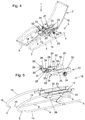
- the substructure 3 has two spring elements 5 arranged parallel to one another and opposite one another on the lying surface 2, as is particularly well shown in FIG Fig. 4 you can see.
- Each of these spring elements 5 has two spring legs 13 and 14, the spring leg 13 being arranged above the spring leg 14 in the operating position shown.
- the feet 4 are arranged on the lower of the spring legs 14.
- the upper spring leg 13 carries the lying surface 2, the adjusting device 16 being arranged in the preferred variants shown here between the substructure 3 or the respective upper spring legs 13 and the lying surface 2.
- the two spring legs 13 and 14 are connected to one another in a connecting region 15 of the respective spring element 5.
- the connection area 15 is C-shaped in this exemplary embodiment.
- the connection area 15 is directed towards the foot end 50 of the lying surface 2.
- the spring legs 13 and 14 run towards Head end 43 of the lying surface 2 apart at least in regions.
- the adjustment device 16 is designed like a slide and allows the lying surface 2 to be adjusted in the longitudinal directions 17 relative to the substructure 3 or to the spring elements 5 and the feet 4. This is largely a horizontal adjustment, which, as said above, but also can have vertical components.
- the structure of the adjusting device 16 of the exemplary embodiments shown here is explained below with reference to FIG 4 to 6 explained in more detail.
- the spring elements 5 elastically pretension the lying surface 2 in the direction 6 away from the base 4 or the base 4.
- the lying surface 2 is in, in 1 and 2 Unloaded state shown is held elastically biased by a limiting element 7 of the reclining furniture.
- This elastic pretension could be demonstrated by the fact that if the limiting element 7 were released, the lying surface would be deflected further away from the spring feet 4 in the direction 6 from the feet 4 than in the initial position according to FIG 1 and 2 is the case in the unloaded state.
- the limiting element 7 is a kind of stop, which holds the spring elements 5 in the prestressed state even when the lying surface 2 is unloaded.
- the two lower spring legs 14 of the two spring elements 5 are rigidly connected to one another via a stop bracket 20.
- the opposite end of the limiting element 7 is connected to a component of the adjusting device 16 which is fixedly connected to the upper spring legs 13.
- the limiting element 7 could of course also be connected in a different way to the spring legs 13 and 14 in order to keep the spring elements 5 elastically biased even in the unloaded state.
- the limiting element 7 is of course not must necessarily be designed as a belt or loop. It could also be other components that hold the spring element 5 or the lying surface 2 elastically pre-stressed in the unloaded state.
- a stop element 8 is also provided in addition to the limiting element 7. This limits the deflection of the lying surface 2 in the loaded state in the direction 9 towards the base 4. In the event of an overload or an excessive load on the lying surface 2, the stop element 8 thus prevents the spring element 5 from being destroyed or otherwise negatively influenced by overloading.
- the stop element 8 is also attached to the stop bracket 20. With a corresponding deflection of the spring elements 5, it interacts with a counter stop 21 which is fixedly connected to the upper of the spring legs 13.
- Both the limiting element 7 and the stop element 8 can be designed damped, e.g. by giving them a certain elasticity.
- this longitudinal adjustment by means of the adjusting device 16 enables the oscillation frequency for an oscillation to be set as a function of the weight of the person lying on the lying surface 2.
- the adjustment device 16 can be used for weight adjustment.
- the 1 and 2 show the starting position of the lying surface 2 in the unloaded state. If you now place an additional mass 10, for example in the form of a Fig. 3 Person stylized on the lying surface 2, a stressed state is reached in which the lying surface 2 together with the additional mass 10 lying thereon is deflected into an intermediate position. In Fig. 3 the intermediate position is solid shown. The starting position according to Fig. 2 is in Fig. 3 shown in dashed lines. It should be noted that the in Fig. 3 schematically illustrated person or additional mass 10 lies in the position provided for the use of the lying furniture 1 on the lying surface 2 by the head of the person near the head end 43 and the feet of the person near the foot end 50 of the lying surface 2 .
- the intermediate position shown with a solid line allows the lying surface 2 together with the person or additional mass 10 lying thereon to execute a free oscillation or a oscillation which is forced by the breathing of the person and which, with a correspondingly adapted oscillation amplitude, is neither influenced by the limiting element 7 nor by the stop element 8.
- the system comprising the lying surface 2, the substructure 3 and the person lying thereon in the form of the additional mass 10 swings around a virtual pivot point 48, which in this exemplary embodiment is located below the knee area Fig. 3 indicated.
- these vibrations have both vertical and horizontal components.
- the lying surface 2 can also vibrate exclusively vertically or in other directions of vibration.
- the vibration directions 49 also have at least one vertical component.
- the upholstery 19 of the lying surface 2 is not shown, so that one can better see the adjusting device 16.
- the lying surface 2 is completely omitted and the adjusting device 16 is shown in an exploded view.
- the adjusting device 16 is a sled-like construction, the sled 51 on the one hand carrying the lying surface 2 and being fixedly connected to it via the tabs 52 and on the other hand being mounted on the guide rails 23.
- the guide rails 23, together with the toothed rails 22, are fixed to the spring elements 5 or their via the cross member 26 upper spring legs 13 attached.
- the slide 51 which is displaceably mounted thereon in the longitudinal directions 17 has two carrier walls 25 which are rigidly connected to one another by means of the spacer rods 27 and 34.
- a shaft 33 rotatably mounted in the carrier walls 25 is guided through the carrier walls 25 and carries a handwheel 24 fixedly mounted on the shaft 33 at its two opposite ends.
- the shaft 33 also carries two gear wheels 32, which each engage in one of the toothed rails 22.
- the carriage 51 is supported by means of the upper and lower rollers 30 and 31 on the guide rails 23 fixedly connected to the toothed rails 22.
- the lower rollers 31 lie, as is particularly well shown in FIG Fig. 6 can be seen from below on the guide rails 23, while the upper rollers 30 are guided on the top of the guide rails 23.
- the upper rollers 30 are pivotally attached to the respective carrier walls 25 via the levers 28.
- the compression springs 29 ensure that the upper rollers 30 are pressed onto the respective guide rail 23 from above. These compression springs 29 ensure that the slide 51 is guided on the guide rails 23 without play.
- the compression springs 29 are so hard that they have no influence on the vibrations when the lying surface 2 and the additional mass 10 lying thereon vibrate and react as a rigid structure.
- the adjusting device 16 realized in the exemplary embodiments shown here can be actuated by hand by correspondingly turning one of the handwheels 24 in order to adjust the lying surface 2 in the longitudinal directions 17 relative to the substructure 3. It is a self-locking adjustment mechanism. In the exemplary embodiment shown, this is achieved in that the toothed wheels 32 have relatively few teeth, advantageously less than ten teeth, which are also preferably formed with rounded ends. As a result, the position which has been set once is held by itself until the handwheel 24 is actuated again. This self-locking prevents accidental Adjustment of the lying surface 2 in the longitudinal directions 17 during the oscillation process. Of course, the locking of a position once set could also be ensured by a separate clamping, locking or other mechanism. Because of their simple operation, self-locking adjusting devices 16 naturally have corresponding advantages in terms of ease of use.
- the spring legs 13 and 14 of the respective spring element 5 in the first embodiment according to the 1 to 6 and 9 are integrally connected to one another in the C-shaped connecting region 15, the 7 and 8 alternative designs.
- the spring legs 13 and 14 are first manufactured as separate parts and then connected to one another in the connection area 15, for example by screwing, riveting, gluing and the like.
- the connection region 15 is located under the half of the lying surface 2 pointing towards the foot end 50, while the spring legs 13 and 14 diverge at least in regions in the direction towards the head end 43.
- the spring legs 13 and 14 or spring elements 5 can, in particular also in the embodiment variants shown here, consist of different material. It can be metals or metal alloys such as Act steel and the like. However, wood, plastic or other suitable materials could also be used to design the spring elements 5 or spring legs 13 and 14 accordingly.
- the lying surface in the loaded state has a free oscillation with a swiveling frequency between 0.1 and 1 Hertz.
- the lying surface 2 with an additional mass 10 of 85 kg lying on the lying surface 2 after a single deflection from a rest position towards the base 4, has an oscillation frequency between 0.1 and 1 Hertz with a free vibration following the deflection .
- the lying surface 2 can carry out a relatively little damped vibration in the loaded state.
- the lying surface 2 with an additional mass 10 of 85 kg lying on the lying surface 2 after a single deflection from a rest position in the direction towards the base 4 with a free oscillation following the deflection maintains an amplitude greater than or equal to 20%.
- the amplitude maintenance is calculated from the ratio of an amplitude 11 of the sixth oscillation period 46 after deflection to an amplitude 12 of the second oscillation period 47 after deflection.
- the additional mass 10 of 85 kg can be realized in the sense of a standardized measurement by a replacement mass body, as shown in Fig. 9 is shown.
- This replacement mass body has two circular cylinders 39 each with a diameter of 150 mm and a width of 290 mm, each of which has a mass of 40 kg.
- These two circular cylinders 39 are arranged parallel to one another with their cylinder longitudinal axis and are rigidly connected to one another at a distance of 900 mm by means of a connecting rod 40.
- the straight connecting rod 40 weighs 5 kg. Both the connecting rod 40 and the circular cylinder 39 have a homogeneous density distribution.
- the additional mass 10 thus formed in the form of a replacement mass body is placed on the lying surface 2 of the otherwise unloaded lying furniture 1 in such a way that the center of gravity 37 of this additional mass 10 comes to lie on a vertical 38 through the center of gravity 36 of the contact surface 35 of the lying surface 2.
- the vertical 38 runs in a plane of symmetry 42, in which the central longitudinal axis 41 of the lying surface 2 also lies.
- the replacement mass body in the form of the additional mass 10 is aligned with its connecting rod 40 on the central longitudinal axis 41, as shown in FIG Fig. 9 is shown.
- the center of gravity 36 of the contact surface 35 of the lying surface 2 is the geometric center of the contact surface 35 of the lying surface 2 intended for the support of the person or the additional mass 10.
- the additional mass 10 positioned in this way is fixed on the lying surface 2, provided that this is necessary to maintain the position relative to the lying surface 2.
- a one-time deflection of the lying surface 2 together with the additional mass 10 lying thereon takes place from the rest position defined by the intermediate position, for example by pressing down the head end 43 of the lying surface 2 in the direction 9 towards the feet 4.
- a free damped oscillation which is recorded and evaluated to determine the parameters mentioned below.
- the force that is applied during the one-time deflection from the rest position and how far the head end 43 is deflected to excite the vibration is of no further importance as long as a well-measurable vibration signal is generated.
- the excitation of this natural vibration should be so strong that the amplitude curve can be followed and recorded well over at least six vibrations. On the other hand, the excitation should not be so strong that the limiting element 7 or the stop element 8 disturb the free vibration.
- Different measuring systems can be used to record the free vibration and different measuring points can be observed on the lying surface 2.
- a point of the lying surface 2 should be selected at which the vibration amplitude is as large as possible. In the exemplary embodiment shown, this is the measurement point 44 at the head end 43 of the lying surface 2.
- Various measuring systems known per se can be used to record the amplitude curve 45 of the free oscillation as a function of time. It is important that these measuring systems do not significantly interfere with the vibration behavior of the lying surface 2 together with the additional mass 10. It is e.g. optical recording as a function of time is conceivable by optically recording the pivoting process of the measuring point 44 from the side as a function of time using a film or the like. Known displacement or acceleration measuring sensors could also be attached to the measuring point 44, which record the path or the acceleration of the measuring point during the oscillation as a function of time.
- Fig. 10 shows an example of a measurement result recorded in this way.
- the amplitude curve 45 of a relative amplitude Arel against time t is shown.
- the oscillation frequency can be calculated from this result representation as the reciprocal of the duration of one of the oscillation periods 46 or 47. Should the oscillation frequency change between the second oscillation period 47 and the sixth oscillation period 46, arithmetic averaging should take place over these two oscillation periods 46 and 47.
- the first oscillation period lying before the second oscillation period 47 is not used, since this can still be disturbed by the excitation of the oscillation.
- To determine the start and end of a respective oscillation period 46 and 47 both the zero crossing of the signal and the distance from two adjacent maxima can be used.
- an oscillation frequency or natural frequency between 0.1 Hertz and 1 Hertz results in any case with this evaluation.
- the ratio of the amplitude 11 is used to calculate the amplitude maintenance sixth oscillation period 46 after deflection to the amplitude 12 of the second oscillation period 47 after deflection.
- This amplitude maintenance should be less than or equal to 20%.
- the maximum amplitude in the respective oscillation period is advantageously used for determining the amplitude.
- the relative amplitude Arel is standardized so that the maximum amplitude 12 of the second oscillation period 47 corresponds to 100%.
- the maximum amplitude 11 of the sixth oscillation period 46 corresponds to 50%, so that in the example shown there is an amplitude conservation of 50%.
Landscapes
- Health & Medical Sciences (AREA)
- General Health & Medical Sciences (AREA)
- Epidemiology (AREA)
- Pain & Pain Management (AREA)
- Physical Education & Sports Medicine (AREA)
- Rehabilitation Therapy (AREA)
- Life Sciences & Earth Sciences (AREA)
- Animal Behavior & Ethology (AREA)
- Public Health (AREA)
- Veterinary Medicine (AREA)
- Dentistry (AREA)
- Chairs For Special Purposes, Such As Reclining Chairs (AREA)
Claims (9)
- Meuble de relaxation (1) avec une surface pour s'allonger (2) et une base (3) pouvant être posée sur un sol et soutenant la surface pour s'allonger (2), la base (3) présentant au moins un piétement (4) et au moins un élément ressort (5) disposé entre le piètement (4) et la surface pour s'allonger (2), et la surface pour s'allonger (2) étant logée sur l'élément de ressort (5), l'élément de ressort (5) assurant une précontrainte élastique de la surface pour s'allonger (2) dans une direction (6) opposée au piètement (4), et la surface pour s'allonger (2), à l'état non chargée, étant maintenue en précontrainte élastique par un élément de limitation (7) du meuble de relaxation (1), caractérisé en ce que la surface pour s'allonger (2) avec une masse supplémentaire (10) de 85 kg reposant sur la surface pour s'allonger (2) présente une fréquence d'oscillation comprise entre 0,1 et 1 Hertz après une seule déviation depuis une position de repos en direction du piètement (4) lors d'une oscillation libre suivant la déviation.
- Meuble de relaxation (1) selon la revendication 1, caractérisé en ce que l'élément de limitation (7) limite une déviation dans la direction (6) opposée au piètement (4) de la surface pour s'allonger (2) à l'état non chargée.
- Meuble de relaxation (1) selon la revendication 1 ou 2, caractérisé en ce que le meuble de relaxation (1) est muni d'un élément de butée (8) pour limiter une déviation de la surface pour s'allonger (2) à l'état chargée dans une direction (9) vers le piètement (4).
- Meuble de relaxation (1) selon l'une des revendications 1 à 3, caractérisé en ce que la surface pour s'allonger (2) à l'état non chargée est disposée dans une position de départ et à l'état chargée avec la masse supplémentaire (10) de 85 kg reposant sur la surface pour s'allonger (2) dans une position intermédiaire déviée par rapport à la position de départ, la surface pour s'allonger (2) à l'état chargée pouvant osciller librement autour de la position intermédiaire déviée.
- Meuble de relaxation (1) selon l'une des revendications 1 à 4, caractérisé en ce que la surface pour s'allonger (2) avec la masse supplémentaire (10) de 85 kg reposant sur la surface du piètement (2), après une seule déviation depuis une position de repos en direction du piètement (4), présente un maintien d'amplitude supérieur ou égal à 20 % lors de l'oscillation libre suivant la déviation, le maintien de l'amplitude étant calculé à partir du rapport entre une amplitude (11) de la sixième période d'oscillation (46) suivant la déviation et une amplitude (12) de la deuxième période d'oscillation (47) suivant la déviation.
- Meuble de relaxation (1) selon l'une des revendications 1 à 5, caractérisé en ce que ledit au moins un élément ressort (5) présente deux branches ressort (13, 14) qui sont reliées entre elles dans une zone de liaison (15) et qui sont de préférence disposées en s'écartant l'une de l'autre depuis la zone de liaison (15) au moins à l'état non chargée et au moins par endroits.
- Meuble de relaxation (1) selon l'une des revendications 1 à 6, caractérisé en ce que ledit au moins un élément ressort (5) présente deux branches ressort (13, 14) qui sont reliées entre elles en étant d'un seul tenant dans une zone de liaison (15) de préférence en forme de C.
- Meuble de relaxation (1) selon l'une des revendications 1 à 7, caractérisé en ce que le meuble de relaxation (1) présente un dispositif de réglage (16) pour le réglage de la surface pour s'allonger (2) par rapport à l'élément ressort (5) dans des directions longitudinales opposées (17) de la surface pour s'allonger (2).
- Utilisation d'un meuble de relaxation (1) selon l'une des revendications 1 à 8, caractérisée en ce qu'une personne s'allonge sur la surface pour s'allonger (2) ce qui fait dévier la surface pour s'allonger (2) d'une position de départ, que prend la surface pour s'allonger (2) quand elle est dans un état non chargée, vers une position intermédiaire déviée par rapport à la position de départ, et la surface pour s'allonger (2) avec la personne couchée dessus est entraînée depuis la position intermédiaire dans une oscillation stimulée uniquement par la respiration de la personne.
Applications Claiming Priority (2)
| Application Number | Priority Date | Filing Date | Title |
|---|---|---|---|
| ATA492/2016A AT519127B1 (de) | 2016-10-24 | 2016-10-24 | Liegemöbel |
| PCT/AT2017/000069 WO2018076031A1 (fr) | 2016-10-24 | 2017-09-29 | Meuble de relaxation |
Publications (2)
| Publication Number | Publication Date |
|---|---|
| EP3528665A1 EP3528665A1 (fr) | 2019-08-28 |
| EP3528665B1 true EP3528665B1 (fr) | 2020-07-29 |
Family
ID=60117398
Family Applications (1)
| Application Number | Title | Priority Date | Filing Date |
|---|---|---|---|
| EP17784526.0A Active EP3528665B1 (fr) | 2016-10-24 | 2017-09-29 | Meuble de relaxation |
Country Status (4)
| Country | Link |
|---|---|
| US (1) | US10939763B2 (fr) |
| EP (1) | EP3528665B1 (fr) |
| AT (1) | AT519127B1 (fr) |
| WO (1) | WO2018076031A1 (fr) |
Families Citing this family (2)
| Publication number | Priority date | Publication date | Assignee | Title |
|---|---|---|---|---|
| US10631651B1 (en) * | 2019-08-06 | 2020-04-28 | Sunflow, Inc. | Chair |
| CN118457389B (zh) * | 2024-07-10 | 2024-09-20 | 厦门家乐其婴儿用品有限公司 | 一种车载式婴幼儿睡篮及其配合的婴儿床 |
Family Cites Families (26)
| Publication number | Priority date | Publication date | Assignee | Title |
|---|---|---|---|---|
| FR1300265A (fr) | 1961-06-19 | 1962-08-03 | Suspension pour sièges | |
| US4141095A (en) * | 1976-06-09 | 1979-02-27 | Kouji Adachi | Electronic cradle |
| GB1591749A (en) * | 1976-11-24 | 1981-06-24 | Rawolle K C | Attachment for a bouncing baby cradle |
| US4081869A (en) * | 1977-02-01 | 1978-04-04 | Richard Graham Ash | Infant's cradle holder |
| DE8415577U1 (de) | 1984-05-22 | 1984-12-06 | Glasmacher, Herbert, 5600 Wuppertal | Entspannungs-liegestuhl |
| US4850645A (en) * | 1986-11-06 | 1989-07-25 | Foy Crockett | Lifting apparatus for a seating structure |
| US4790596A (en) * | 1987-06-26 | 1988-12-13 | Shifferaw Tessema D | Resilient chair |
| US5503458A (en) * | 1993-07-02 | 1996-04-02 | Item New Product Development, Inc. | Portable infant seat |
| US5615428A (en) * | 1996-06-24 | 1997-04-01 | Li; Hsing | Elastic cradle |
| TW411815U (en) * | 2000-03-31 | 2000-11-11 | Link Treasure Ltd | Foldable baby rocking chair |
| US6361106B1 (en) * | 2000-07-11 | 2002-03-26 | Mien Chen Huang | Folding collapsible frame structure for a baby rocking chair |
| DE20020607U1 (de) | 2000-12-04 | 2001-03-01 | Probst, Bernd, 96317 Kronach | Behandlungsliege zur Vibrationstherapie |
| US20030020317A1 (en) * | 2001-07-30 | 2003-01-30 | Charles Keegan | Baby bouncer |
| US6574806B1 (en) | 2001-12-28 | 2003-06-10 | Charles E. Maher | Infant seat rocking device |
| EP1645257B1 (fr) * | 2004-10-08 | 2009-05-20 | Wissner-Bosserhoff GmbH | Lit, notamment lit de malades ou lit de soins |
| US7021711B1 (en) * | 2004-11-04 | 2006-04-04 | Ultra-Mek, Inc. | Rocking-reclining seating unit with motion lock |
| US7850220B2 (en) * | 2005-06-09 | 2010-12-14 | Intier Automotive Inc. | Mono leg transformer seat |
| US7850232B2 (en) * | 2007-03-09 | 2010-12-14 | Ashley Furniture Industries, Inc. | Zero clearance recliner mechanism |
| DE102008032232A1 (de) * | 2008-07-09 | 2010-01-14 | Bär, Manfred | Behandlungsliege |
| ITMI20091861A1 (it) * | 2009-10-27 | 2011-04-28 | Capri Design S R L | Telaio con lamine d'appoggio a flessibilità diminuita utilizzabile nelle sdraiette per bimbi |
| US20110260507A1 (en) * | 2010-04-27 | 2011-10-27 | Parness Michael A | Convertible infant rocker |
| CH704322A2 (de) | 2011-01-11 | 2012-07-13 | Philipp Buehler | Therapeutischer Schaukelstuhl. |
| DE102011012378B4 (de) * | 2011-02-21 | 2013-09-12 | Dumitru Florian Luca | Massagebett |
| US9314101B2 (en) | 2013-03-01 | 2016-04-19 | La-Z-Boy Incorporated | Restricted rocker spring assembly |
| DE102013105158B4 (de) | 2013-05-21 | 2015-10-29 | göckel-design e.K. | Massageliege |
| DE202015005849U1 (de) | 2015-08-23 | 2015-11-03 | Kurperle Gmbh | Trainings- und Therapieeinrichtung auf Schwingungsbasis |
-
2016
- 2016-10-24 AT ATA492/2016A patent/AT519127B1/de not_active IP Right Cessation
-
2017
- 2017-09-29 US US16/341,668 patent/US10939763B2/en active Active
- 2017-09-29 WO PCT/AT2017/000069 patent/WO2018076031A1/fr not_active Ceased
- 2017-09-29 EP EP17784526.0A patent/EP3528665B1/fr active Active
Non-Patent Citations (1)
| Title |
|---|
| None * |
Also Published As
| Publication number | Publication date |
|---|---|
| US20190374032A1 (en) | 2019-12-12 |
| AT519127B1 (de) | 2018-04-15 |
| AT519127A4 (de) | 2018-04-15 |
| EP3528665A1 (fr) | 2019-08-28 |
| US10939763B2 (en) | 2021-03-09 |
| WO2018076031A1 (fr) | 2018-05-03 |
Similar Documents
| Publication | Publication Date | Title |
|---|---|---|
| DE19840800C1 (de) | Kraftmeßgerät zur Messung der Kraftfähigkeit einzelner Muskelgruppen eines Menschen | |
| DE4244657A1 (de) | Aktivdynamische Sitzvorrichtung | |
| DE102005005089A1 (de) | Tragelement für ein Sitzmöbel | |
| DE1753671B1 (de) | Sessel mit verstellbarer sitzflaeche und oder rueckenlehne | |
| DE8319792U1 (de) | Buerostuhl | |
| AT519127B1 (de) | Liegemöbel | |
| DE2822574A1 (de) | Stuhl | |
| DE3027807A1 (de) | Ausschiebemechanik fuer fuss-stuetze mit parallel zueinander ausschibbaren bauteilen | |
| CH667000A5 (de) | Liegemoebel mit pendelrahmen. | |
| AT392891B (de) | Liegemoebel | |
| DE1149147B (de) | Anlehnstuetze fuer stehend Arbeitende | |
| DE2542267A1 (de) | Vorrichtung zur verstellung der elastischen durchbiegung eines lagerkoerpers an einem liegemoebelgestell | |
| DE2732193C2 (de) | Sitz- und Liegemöbel aus mehreren klappbaren Polsterteilen | |
| WO2020019007A1 (fr) | Caillebotis | |
| EP0056454A2 (fr) | Meuble d'assise, notamment chaise tournante de bureau | |
| DE102013006180B3 (de) | Vorrichtung zur Unterdrückung von Schnarchgeräuschen | |
| DE102008032232A1 (de) | Behandlungsliege | |
| EP2721960B1 (fr) | Meuble siège, en particulier chaise de bureau rotative | |
| DE2709960A1 (de) | Sitzmoebel, insbesondere drehbarer arbeitsstuhl | |
| EP3972458A1 (fr) | Lit ou siège | |
| DE102004035686B4 (de) | Bewegliches Liegemöbel, insbesondere Babywiege | |
| EP1754429A1 (fr) | Système de ressort inférieur pour supporté le matelas | |
| DE3739216A1 (de) | Stossdaempferanordnung fuer rollstuehle | |
| AT219216B (de) | Betteinsatz | |
| DE202016106819U1 (de) | Sitzmöbel |
Legal Events
| Date | Code | Title | Description |
|---|---|---|---|
| STAA | Information on the status of an ep patent application or granted ep patent |
Free format text: STATUS: UNKNOWN |
|
| STAA | Information on the status of an ep patent application or granted ep patent |
Free format text: STATUS: THE INTERNATIONAL PUBLICATION HAS BEEN MADE |
|
| PUAI | Public reference made under article 153(3) epc to a published international application that has entered the european phase |
Free format text: ORIGINAL CODE: 0009012 |
|
| STAA | Information on the status of an ep patent application or granted ep patent |
Free format text: STATUS: REQUEST FOR EXAMINATION WAS MADE |
|
| 17P | Request for examination filed |
Effective date: 20190313 |
|
| AK | Designated contracting states |
Kind code of ref document: A1 Designated state(s): AL AT BE BG CH CY CZ DE DK EE ES FI FR GB GR HR HU IE IS IT LI LT LU LV MC MK MT NL NO PL PT RO RS SE SI SK SM TR |
|
| AX | Request for extension of the european patent |
Extension state: BA ME |
|
| DAV | Request for validation of the european patent (deleted) | ||
| DAX | Request for extension of the european patent (deleted) | ||
| GRAP | Despatch of communication of intention to grant a patent |
Free format text: ORIGINAL CODE: EPIDOSNIGR1 |
|
| STAA | Information on the status of an ep patent application or granted ep patent |
Free format text: STATUS: GRANT OF PATENT IS INTENDED |
|
| INTG | Intention to grant announced |
Effective date: 20200424 |
|
| GRAS | Grant fee paid |
Free format text: ORIGINAL CODE: EPIDOSNIGR3 |
|
| GRAA | (expected) grant |
Free format text: ORIGINAL CODE: 0009210 |
|
| STAA | Information on the status of an ep patent application or granted ep patent |
Free format text: STATUS: THE PATENT HAS BEEN GRANTED |
|
| AK | Designated contracting states |
Kind code of ref document: B1 Designated state(s): AL AT BE BG CH CY CZ DE DK EE ES FI FR GB GR HR HU IE IS IT LI LT LU LV MC MK MT NL NO PL PT RO RS SE SI SK SM TR |
|
| REG | Reference to a national code |
Ref country code: CH Ref legal event code: EP |
|
| REG | Reference to a national code |
Ref country code: DE Ref legal event code: R096 Ref document number: 502017006478 Country of ref document: DE |
|
| REG | Reference to a national code |
Ref country code: AT Ref legal event code: REF Ref document number: 1294793 Country of ref document: AT Kind code of ref document: T Effective date: 20200815 |
|
| REG | Reference to a national code |
Ref country code: IE Ref legal event code: FG4D Free format text: LANGUAGE OF EP DOCUMENT: GERMAN |
|
| REG | Reference to a national code |
Ref country code: CH Ref legal event code: NV Representative=s name: ALDO ROEMPLER PATENTANWALT, CH |
|
| REG | Reference to a national code |
Ref country code: LT Ref legal event code: MG4D |
|
| REG | Reference to a national code |
Ref country code: NL Ref legal event code: MP Effective date: 20200729 |
|
| PG25 | Lapsed in a contracting state [announced via postgrant information from national office to epo] |
Ref country code: SE Free format text: LAPSE BECAUSE OF FAILURE TO SUBMIT A TRANSLATION OF THE DESCRIPTION OR TO PAY THE FEE WITHIN THE PRESCRIBED TIME-LIMIT Effective date: 20200729 Ref country code: BG Free format text: LAPSE BECAUSE OF FAILURE TO SUBMIT A TRANSLATION OF THE DESCRIPTION OR TO PAY THE FEE WITHIN THE PRESCRIBED TIME-LIMIT Effective date: 20201029 Ref country code: FI Free format text: LAPSE BECAUSE OF FAILURE TO SUBMIT A TRANSLATION OF THE DESCRIPTION OR TO PAY THE FEE WITHIN THE PRESCRIBED TIME-LIMIT Effective date: 20200729 Ref country code: NO Free format text: LAPSE BECAUSE OF FAILURE TO SUBMIT A TRANSLATION OF THE DESCRIPTION OR TO PAY THE FEE WITHIN THE PRESCRIBED TIME-LIMIT Effective date: 20201029 Ref country code: PT Free format text: LAPSE BECAUSE OF FAILURE TO SUBMIT A TRANSLATION OF THE DESCRIPTION OR TO PAY THE FEE WITHIN THE PRESCRIBED TIME-LIMIT Effective date: 20201130 Ref country code: GR Free format text: LAPSE BECAUSE OF FAILURE TO SUBMIT A TRANSLATION OF THE DESCRIPTION OR TO PAY THE FEE WITHIN THE PRESCRIBED TIME-LIMIT Effective date: 20201030 Ref country code: LT Free format text: LAPSE BECAUSE OF FAILURE TO SUBMIT A TRANSLATION OF THE DESCRIPTION OR TO PAY THE FEE WITHIN THE PRESCRIBED TIME-LIMIT Effective date: 20200729 Ref country code: HR Free format text: LAPSE BECAUSE OF FAILURE TO SUBMIT A TRANSLATION OF THE DESCRIPTION OR TO PAY THE FEE WITHIN THE PRESCRIBED TIME-LIMIT Effective date: 20200729 Ref country code: ES Free format text: LAPSE BECAUSE OF FAILURE TO SUBMIT A TRANSLATION OF THE DESCRIPTION OR TO PAY THE FEE WITHIN THE PRESCRIBED TIME-LIMIT Effective date: 20200729 |
|
| PG25 | Lapsed in a contracting state [announced via postgrant information from national office to epo] |
Ref country code: LV Free format text: LAPSE BECAUSE OF FAILURE TO SUBMIT A TRANSLATION OF THE DESCRIPTION OR TO PAY THE FEE WITHIN THE PRESCRIBED TIME-LIMIT Effective date: 20200729 Ref country code: PL Free format text: LAPSE BECAUSE OF FAILURE TO SUBMIT A TRANSLATION OF THE DESCRIPTION OR TO PAY THE FEE WITHIN THE PRESCRIBED TIME-LIMIT Effective date: 20200729 Ref country code: RS Free format text: LAPSE BECAUSE OF FAILURE TO SUBMIT A TRANSLATION OF THE DESCRIPTION OR TO PAY THE FEE WITHIN THE PRESCRIBED TIME-LIMIT Effective date: 20200729 Ref country code: IS Free format text: LAPSE BECAUSE OF FAILURE TO SUBMIT A TRANSLATION OF THE DESCRIPTION OR TO PAY THE FEE WITHIN THE PRESCRIBED TIME-LIMIT Effective date: 20201129 |
|
| PG25 | Lapsed in a contracting state [announced via postgrant information from national office to epo] |
Ref country code: NL Free format text: LAPSE BECAUSE OF FAILURE TO SUBMIT A TRANSLATION OF THE DESCRIPTION OR TO PAY THE FEE WITHIN THE PRESCRIBED TIME-LIMIT Effective date: 20200729 |
|
| PG25 | Lapsed in a contracting state [announced via postgrant information from national office to epo] |
Ref country code: SM Free format text: LAPSE BECAUSE OF FAILURE TO SUBMIT A TRANSLATION OF THE DESCRIPTION OR TO PAY THE FEE WITHIN THE PRESCRIBED TIME-LIMIT Effective date: 20200729 Ref country code: EE Free format text: LAPSE BECAUSE OF FAILURE TO SUBMIT A TRANSLATION OF THE DESCRIPTION OR TO PAY THE FEE WITHIN THE PRESCRIBED TIME-LIMIT Effective date: 20200729 Ref country code: RO Free format text: LAPSE BECAUSE OF FAILURE TO SUBMIT A TRANSLATION OF THE DESCRIPTION OR TO PAY THE FEE WITHIN THE PRESCRIBED TIME-LIMIT Effective date: 20200729 Ref country code: DK Free format text: LAPSE BECAUSE OF FAILURE TO SUBMIT A TRANSLATION OF THE DESCRIPTION OR TO PAY THE FEE WITHIN THE PRESCRIBED TIME-LIMIT Effective date: 20200729 Ref country code: CZ Free format text: LAPSE BECAUSE OF FAILURE TO SUBMIT A TRANSLATION OF THE DESCRIPTION OR TO PAY THE FEE WITHIN THE PRESCRIBED TIME-LIMIT Effective date: 20200729 |
|
| REG | Reference to a national code |
Ref country code: DE Ref legal event code: R097 Ref document number: 502017006478 Country of ref document: DE |
|
| PG25 | Lapsed in a contracting state [announced via postgrant information from national office to epo] |
Ref country code: AL Free format text: LAPSE BECAUSE OF FAILURE TO SUBMIT A TRANSLATION OF THE DESCRIPTION OR TO PAY THE FEE WITHIN THE PRESCRIBED TIME-LIMIT Effective date: 20200729 |
|
| PLBE | No opposition filed within time limit |
Free format text: ORIGINAL CODE: 0009261 |
|
| STAA | Information on the status of an ep patent application or granted ep patent |
Free format text: STATUS: NO OPPOSITION FILED WITHIN TIME LIMIT |
|
| PG25 | Lapsed in a contracting state [announced via postgrant information from national office to epo] |
Ref country code: SK Free format text: LAPSE BECAUSE OF FAILURE TO SUBMIT A TRANSLATION OF THE DESCRIPTION OR TO PAY THE FEE WITHIN THE PRESCRIBED TIME-LIMIT Effective date: 20200729 Ref country code: LU Free format text: LAPSE BECAUSE OF NON-PAYMENT OF DUE FEES Effective date: 20200929 |
|
| 26N | No opposition filed |
Effective date: 20210430 |
|
| PG25 | Lapsed in a contracting state [announced via postgrant information from national office to epo] |
Ref country code: SI Free format text: LAPSE BECAUSE OF FAILURE TO SUBMIT A TRANSLATION OF THE DESCRIPTION OR TO PAY THE FEE WITHIN THE PRESCRIBED TIME-LIMIT Effective date: 20200729 Ref country code: IE Free format text: LAPSE BECAUSE OF NON-PAYMENT OF DUE FEES Effective date: 20200929 |
|
| PG25 | Lapsed in a contracting state [announced via postgrant information from national office to epo] |
Ref country code: TR Free format text: LAPSE BECAUSE OF FAILURE TO SUBMIT A TRANSLATION OF THE DESCRIPTION OR TO PAY THE FEE WITHIN THE PRESCRIBED TIME-LIMIT Effective date: 20200729 Ref country code: MT Free format text: LAPSE BECAUSE OF FAILURE TO SUBMIT A TRANSLATION OF THE DESCRIPTION OR TO PAY THE FEE WITHIN THE PRESCRIBED TIME-LIMIT Effective date: 20200729 Ref country code: CY Free format text: LAPSE BECAUSE OF FAILURE TO SUBMIT A TRANSLATION OF THE DESCRIPTION OR TO PAY THE FEE WITHIN THE PRESCRIBED TIME-LIMIT Effective date: 20200729 |
|
| PG25 | Lapsed in a contracting state [announced via postgrant information from national office to epo] |
Ref country code: MC Free format text: LAPSE BECAUSE OF FAILURE TO SUBMIT A TRANSLATION OF THE DESCRIPTION OR TO PAY THE FEE WITHIN THE PRESCRIBED TIME-LIMIT Effective date: 20200729 Ref country code: MK Free format text: LAPSE BECAUSE OF FAILURE TO SUBMIT A TRANSLATION OF THE DESCRIPTION OR TO PAY THE FEE WITHIN THE PRESCRIBED TIME-LIMIT Effective date: 20200729 |
|
| REG | Reference to a national code |
Ref country code: CH Ref legal event code: U11 Free format text: ST27 STATUS EVENT CODE: U-0-0-U10-U11 (AS PROVIDED BY THE NATIONAL OFFICE) Effective date: 20251001 |
|
| PGFP | Annual fee paid to national office [announced via postgrant information from national office to epo] |
Ref country code: DE Payment date: 20250926 Year of fee payment: 9 |
|
| PGFP | Annual fee paid to national office [announced via postgrant information from national office to epo] |
Ref country code: IT Payment date: 20250922 Year of fee payment: 9 |
|
| PGFP | Annual fee paid to national office [announced via postgrant information from national office to epo] |
Ref country code: BE Payment date: 20250925 Year of fee payment: 9 Ref country code: GB Payment date: 20250923 Year of fee payment: 9 |
|
| PGFP | Annual fee paid to national office [announced via postgrant information from national office to epo] |
Ref country code: FR Payment date: 20250925 Year of fee payment: 9 Ref country code: AT Payment date: 20250916 Year of fee payment: 9 |
|
| PGFP | Annual fee paid to national office [announced via postgrant information from national office to epo] |
Ref country code: CH Payment date: 20251001 Year of fee payment: 9 |