EP3528731B1 - Dilatationsballon mit rf-energiefreisetzung - Google Patents
Dilatationsballon mit rf-energiefreisetzung Download PDFInfo
- Publication number
- EP3528731B1 EP3528731B1 EP17788396.4A EP17788396A EP3528731B1 EP 3528731 B1 EP3528731 B1 EP 3528731B1 EP 17788396 A EP17788396 A EP 17788396A EP 3528731 B1 EP3528731 B1 EP 3528731B1
- Authority
- EP
- European Patent Office
- Prior art keywords
- wires
- wire assembly
- dilator
- distal end
- wire
- Prior art date
- Legal status (The legal status is an assumption and is not a legal conclusion. Google has not performed a legal analysis and makes no representation as to the accuracy of the status listed.)
- Not-in-force
Links
- 230000010339 dilation Effects 0.000 title description 75
- 239000012530 fluid Substances 0.000 claims description 19
- 238000000576 coating method Methods 0.000 claims description 11
- 239000003814 drug Substances 0.000 claims description 11
- 239000011248 coating agent Substances 0.000 claims description 10
- 229940079593 drug Drugs 0.000 claims description 10
- 230000006854 communication Effects 0.000 claims description 8
- 238000004891 communication Methods 0.000 claims description 8
- 230000007704 transition Effects 0.000 claims description 5
- 238000004520 electroporation Methods 0.000 claims description 4
- 239000000463 material Substances 0.000 claims description 4
- HLXZNVUGXRDIFK-UHFFFAOYSA-N nickel titanium Chemical compound [Ti].[Ti].[Ti].[Ti].[Ti].[Ti].[Ti].[Ti].[Ti].[Ti].[Ti].[Ni].[Ni].[Ni].[Ni].[Ni].[Ni].[Ni].[Ni].[Ni].[Ni].[Ni].[Ni].[Ni].[Ni] HLXZNVUGXRDIFK-UHFFFAOYSA-N 0.000 claims description 2
- 229910001000 nickel titanium Inorganic materials 0.000 claims description 2
- 229910052709 silver Inorganic materials 0.000 claims description 2
- 239000004332 silver Substances 0.000 claims description 2
- 239000000126 substance Substances 0.000 claims description 2
- 230000001225 therapeutic effect Effects 0.000 claims 1
- 238000000034 method Methods 0.000 description 49
- 210000004086 maxillary sinus Anatomy 0.000 description 21
- 210000001519 tissue Anatomy 0.000 description 19
- 238000002675 image-guided surgery Methods 0.000 description 18
- 210000003695 paranasal sinus Anatomy 0.000 description 16
- 230000000916 dilatatory effect Effects 0.000 description 13
- 210000001331 nose Anatomy 0.000 description 13
- 210000003128 head Anatomy 0.000 description 11
- 238000005286 illumination Methods 0.000 description 11
- 230000002262 irrigation Effects 0.000 description 11
- 238000003973 irrigation Methods 0.000 description 11
- 210000003928 nasal cavity Anatomy 0.000 description 11
- 230000008878 coupling Effects 0.000 description 10
- 238000010168 coupling process Methods 0.000 description 10
- 238000005859 coupling reaction Methods 0.000 description 10
- 238000001356 surgical procedure Methods 0.000 description 9
- 210000003484 anatomy Anatomy 0.000 description 8
- 239000000835 fiber Substances 0.000 description 8
- 238000012800 visualization Methods 0.000 description 8
- FAPWRFPIFSIZLT-UHFFFAOYSA-M Sodium chloride Chemical compound [Na+].[Cl-] FAPWRFPIFSIZLT-UHFFFAOYSA-M 0.000 description 6
- 230000014509 gene expression Effects 0.000 description 6
- 239000011780 sodium chloride Substances 0.000 description 6
- 230000002411 adverse Effects 0.000 description 5
- 230000005672 electromagnetic field Effects 0.000 description 5
- 210000003800 pharynx Anatomy 0.000 description 5
- 231100000241 scar Toxicity 0.000 description 5
- 210000002388 eustachian tube Anatomy 0.000 description 4
- 238000012986 modification Methods 0.000 description 4
- 230000004048 modification Effects 0.000 description 4
- 230000005855 radiation Effects 0.000 description 4
- 210000000988 bone and bone Anatomy 0.000 description 3
- 238000004140 cleaning Methods 0.000 description 3
- 208000037265 diseases, disorders, signs and symptoms Diseases 0.000 description 3
- 230000015654 memory Effects 0.000 description 3
- 238000012545 processing Methods 0.000 description 3
- 238000007674 radiofrequency ablation Methods 0.000 description 3
- 230000000007 visual effect Effects 0.000 description 3
- 238000002591 computed tomography Methods 0.000 description 2
- 238000005516 engineering process Methods 0.000 description 2
- 238000002955 isolation Methods 0.000 description 2
- 210000000867 larynx Anatomy 0.000 description 2
- 238000002595 magnetic resonance imaging Methods 0.000 description 2
- 230000003287 optical effect Effects 0.000 description 2
- BASFCYQUMIYNBI-UHFFFAOYSA-N platinum Chemical compound [Pt] BASFCYQUMIYNBI-UHFFFAOYSA-N 0.000 description 2
- 238000007634 remodeling Methods 0.000 description 2
- 241000894006 Bacteria Species 0.000 description 1
- 241001313846 Calypso Species 0.000 description 1
- IAYPIBMASNFSPL-UHFFFAOYSA-N Ethylene oxide Chemical compound C1CO1 IAYPIBMASNFSPL-UHFFFAOYSA-N 0.000 description 1
- 239000004775 Tyvek Substances 0.000 description 1
- 229920000690 Tyvek Polymers 0.000 description 1
- 238000002679 ablation Methods 0.000 description 1
- 230000006978 adaptation Effects 0.000 description 1
- 239000003242 anti bacterial agent Substances 0.000 description 1
- 229940088710 antibiotic agent Drugs 0.000 description 1
- 230000009286 beneficial effect Effects 0.000 description 1
- 230000007175 bidirectional communication Effects 0.000 description 1
- 230000003115 biocidal effect Effects 0.000 description 1
- 238000001574 biopsy Methods 0.000 description 1
- 230000000740 bleeding effect Effects 0.000 description 1
- 239000008280 blood Substances 0.000 description 1
- 210000004369 blood Anatomy 0.000 description 1
- 239000004020 conductor Substances 0.000 description 1
- 238000012790 confirmation Methods 0.000 description 1
- 238000003745 diagnosis Methods 0.000 description 1
- 239000000032 diagnostic agent Substances 0.000 description 1
- 229940039227 diagnostic agent Drugs 0.000 description 1
- 229910003460 diamond Inorganic materials 0.000 description 1
- 239000010432 diamond Substances 0.000 description 1
- 239000012636 effector Substances 0.000 description 1
- 238000013129 endoscopic sinus surgery Methods 0.000 description 1
- 210000001180 ethmoid sinus Anatomy 0.000 description 1
- 210000004209 hair Anatomy 0.000 description 1
- 238000003780 insertion Methods 0.000 description 1
- 230000037431 insertion Effects 0.000 description 1
- 229910052741 iridium Inorganic materials 0.000 description 1
- GKOZUEZYRPOHIO-UHFFFAOYSA-N iridium atom Chemical compound [Ir] GKOZUEZYRPOHIO-UHFFFAOYSA-N 0.000 description 1
- 238000013507 mapping Methods 0.000 description 1
- 239000007769 metal material Substances 0.000 description 1
- 210000004877 mucosa Anatomy 0.000 description 1
- 239000013307 optical fiber Substances 0.000 description 1
- 229910052697 platinum Inorganic materials 0.000 description 1
- HWLDNSXPUQTBOD-UHFFFAOYSA-N platinum-iridium alloy Chemical class [Ir].[Pt] HWLDNSXPUQTBOD-UHFFFAOYSA-N 0.000 description 1
- 230000008569 process Effects 0.000 description 1
- 238000010926 purge Methods 0.000 description 1
- 238000002601 radiography Methods 0.000 description 1
- 201000009890 sinusitis Diseases 0.000 description 1
- 210000003718 sphenoid sinus Anatomy 0.000 description 1
- 230000001954 sterilising effect Effects 0.000 description 1
- 238000004659 sterilization and disinfection Methods 0.000 description 1
- 239000013589 supplement Substances 0.000 description 1
- 229940124597 therapeutic agent Drugs 0.000 description 1
- 238000012546 transfer Methods 0.000 description 1
- 238000009423 ventilation Methods 0.000 description 1
Images


Classifications
-
- A—HUMAN NECESSITIES
- A61—MEDICAL OR VETERINARY SCIENCE; HYGIENE
- A61B—DIAGNOSIS; SURGERY; IDENTIFICATION
- A61B18/00—Surgical instruments, devices or methods for transferring non-mechanical forms of energy to or from the body
- A61B18/04—Surgical instruments, devices or methods for transferring non-mechanical forms of energy to or from the body by heating
- A61B18/12—Surgical instruments, devices or methods for transferring non-mechanical forms of energy to or from the body by heating by passing a current through the tissue to be heated, e.g. high-frequency current
- A61B18/14—Probes or electrodes therefor
- A61B18/1492—Probes or electrodes therefor having a flexible, catheter-like structure, e.g. for heart ablation
-
- A—HUMAN NECESSITIES
- A61—MEDICAL OR VETERINARY SCIENCE; HYGIENE
- A61B—DIAGNOSIS; SURGERY; IDENTIFICATION
- A61B1/00—Instruments for performing medical examinations of the interior of cavities or tubes of the body by visual or photographical inspection, e.g. endoscopes; Illuminating arrangements therefor
- A61B1/00163—Optical arrangements
- A61B1/00174—Optical arrangements characterised by the viewing angles
- A61B1/00183—Optical arrangements characterised by the viewing angles for variable viewing angles
-
- A—HUMAN NECESSITIES
- A61—MEDICAL OR VETERINARY SCIENCE; HYGIENE
- A61B—DIAGNOSIS; SURGERY; IDENTIFICATION
- A61B1/00—Instruments for performing medical examinations of the interior of cavities or tubes of the body by visual or photographical inspection, e.g. endoscopes; Illuminating arrangements therefor
- A61B1/233—Instruments for performing medical examinations of the interior of cavities or tubes of the body by visual or photographical inspection, e.g. endoscopes; Illuminating arrangements therefor for the nose, i.e. nasoscopes, e.g. testing of patency of Eustachian tubes
-
- A—HUMAN NECESSITIES
- A61—MEDICAL OR VETERINARY SCIENCE; HYGIENE
- A61B—DIAGNOSIS; SURGERY; IDENTIFICATION
- A61B18/00—Surgical instruments, devices or methods for transferring non-mechanical forms of energy to or from the body
- A61B18/04—Surgical instruments, devices or methods for transferring non-mechanical forms of energy to or from the body by heating
- A61B18/12—Surgical instruments, devices or methods for transferring non-mechanical forms of energy to or from the body by heating by passing a current through the tissue to be heated, e.g. high-frequency current
- A61B18/1206—Generators therefor
-
- A—HUMAN NECESSITIES
- A61—MEDICAL OR VETERINARY SCIENCE; HYGIENE
- A61B—DIAGNOSIS; SURGERY; IDENTIFICATION
- A61B34/00—Computer-aided surgery; Manipulators or robots specially adapted for use in surgery
- A61B34/20—Surgical navigation systems; Devices for tracking or guiding surgical instruments, e.g. for frameless stereotaxis
-
- A—HUMAN NECESSITIES
- A61—MEDICAL OR VETERINARY SCIENCE; HYGIENE
- A61M—DEVICES FOR INTRODUCING MEDIA INTO, OR ONTO, THE BODY; DEVICES FOR TRANSDUCING BODY MEDIA OR FOR TAKING MEDIA FROM THE BODY; DEVICES FOR PRODUCING OR ENDING SLEEP OR STUPOR
- A61M25/00—Catheters; Hollow probes
-
- A—HUMAN NECESSITIES
- A61—MEDICAL OR VETERINARY SCIENCE; HYGIENE
- A61M—DEVICES FOR INTRODUCING MEDIA INTO, OR ONTO, THE BODY; DEVICES FOR TRANSDUCING BODY MEDIA OR FOR TAKING MEDIA FROM THE BODY; DEVICES FOR PRODUCING OR ENDING SLEEP OR STUPOR
- A61M25/00—Catheters; Hollow probes
- A61M25/10—Balloon catheters
- A61M25/1018—Balloon inflating or inflation-control devices
- A61M25/10181—Means for forcing inflation fluid into the balloon
-
- A—HUMAN NECESSITIES
- A61—MEDICAL OR VETERINARY SCIENCE; HYGIENE
- A61M—DEVICES FOR INTRODUCING MEDIA INTO, OR ONTO, THE BODY; DEVICES FOR TRANSDUCING BODY MEDIA OR FOR TAKING MEDIA FROM THE BODY; DEVICES FOR PRODUCING OR ENDING SLEEP OR STUPOR
- A61M29/00—Dilators with or without means for introducing media, e.g. remedies
- A61M29/02—Dilators made of swellable material
-
- A—HUMAN NECESSITIES
- A61—MEDICAL OR VETERINARY SCIENCE; HYGIENE
- A61B—DIAGNOSIS; SURGERY; IDENTIFICATION
- A61B18/00—Surgical instruments, devices or methods for transferring non-mechanical forms of energy to or from the body
- A61B2018/00053—Mechanical features of the instrument of device
- A61B2018/00059—Material properties
- A61B2018/00071—Electrical conductivity
- A61B2018/00077—Electrical conductivity high, i.e. electrically conducting
-
- A—HUMAN NECESSITIES
- A61—MEDICAL OR VETERINARY SCIENCE; HYGIENE
- A61B—DIAGNOSIS; SURGERY; IDENTIFICATION
- A61B18/00—Surgical instruments, devices or methods for transferring non-mechanical forms of energy to or from the body
- A61B2018/00053—Mechanical features of the instrument of device
- A61B2018/00059—Material properties
- A61B2018/00071—Electrical conductivity
- A61B2018/00083—Electrical conductivity low, i.e. electrically insulating
-
- A—HUMAN NECESSITIES
- A61—MEDICAL OR VETERINARY SCIENCE; HYGIENE
- A61B—DIAGNOSIS; SURGERY; IDENTIFICATION
- A61B18/00—Surgical instruments, devices or methods for transferring non-mechanical forms of energy to or from the body
- A61B2018/00053—Mechanical features of the instrument of device
- A61B2018/00107—Coatings on the energy applicator
- A61B2018/00154—Coatings on the energy applicator containing and delivering drugs
-
- A—HUMAN NECESSITIES
- A61—MEDICAL OR VETERINARY SCIENCE; HYGIENE
- A61B—DIAGNOSIS; SURGERY; IDENTIFICATION
- A61B18/00—Surgical instruments, devices or methods for transferring non-mechanical forms of energy to or from the body
- A61B2018/00053—Mechanical features of the instrument of device
- A61B2018/0016—Energy applicators arranged in a two- or three dimensional array
-
- A—HUMAN NECESSITIES
- A61—MEDICAL OR VETERINARY SCIENCE; HYGIENE
- A61B—DIAGNOSIS; SURGERY; IDENTIFICATION
- A61B18/00—Surgical instruments, devices or methods for transferring non-mechanical forms of energy to or from the body
- A61B2018/00053—Mechanical features of the instrument of device
- A61B2018/00214—Expandable means emitting energy, e.g. by elements carried thereon
- A61B2018/0022—Balloons
-
- A—HUMAN NECESSITIES
- A61—MEDICAL OR VETERINARY SCIENCE; HYGIENE
- A61B—DIAGNOSIS; SURGERY; IDENTIFICATION
- A61B18/00—Surgical instruments, devices or methods for transferring non-mechanical forms of energy to or from the body
- A61B2018/00053—Mechanical features of the instrument of device
- A61B2018/00214—Expandable means emitting energy, e.g. by elements carried thereon
- A61B2018/0022—Balloons
- A61B2018/00244—Balloons adapted to separate target tissue from other tissue
-
- A—HUMAN NECESSITIES
- A61—MEDICAL OR VETERINARY SCIENCE; HYGIENE
- A61B—DIAGNOSIS; SURGERY; IDENTIFICATION
- A61B18/00—Surgical instruments, devices or methods for transferring non-mechanical forms of energy to or from the body
- A61B2018/00053—Mechanical features of the instrument of device
- A61B2018/00214—Expandable means emitting energy, e.g. by elements carried thereon
- A61B2018/00267—Expandable means emitting energy, e.g. by elements carried thereon having a basket shaped structure
-
- A—HUMAN NECESSITIES
- A61—MEDICAL OR VETERINARY SCIENCE; HYGIENE
- A61B—DIAGNOSIS; SURGERY; IDENTIFICATION
- A61B18/00—Surgical instruments, devices or methods for transferring non-mechanical forms of energy to or from the body
- A61B2018/00315—Surgical instruments, devices or methods for transferring non-mechanical forms of energy to or from the body for treatment of particular body parts
- A61B2018/00321—Head or parts thereof
- A61B2018/00327—Ear, nose or throat
-
- A—HUMAN NECESSITIES
- A61—MEDICAL OR VETERINARY SCIENCE; HYGIENE
- A61B—DIAGNOSIS; SURGERY; IDENTIFICATION
- A61B18/00—Surgical instruments, devices or methods for transferring non-mechanical forms of energy to or from the body
- A61B2018/00571—Surgical instruments, devices or methods for transferring non-mechanical forms of energy to or from the body for achieving a particular surgical effect
- A61B2018/00577—Ablation
-
- A—HUMAN NECESSITIES
- A61—MEDICAL OR VETERINARY SCIENCE; HYGIENE
- A61B—DIAGNOSIS; SURGERY; IDENTIFICATION
- A61B18/00—Surgical instruments, devices or methods for transferring non-mechanical forms of energy to or from the body
- A61B2018/00571—Surgical instruments, devices or methods for transferring non-mechanical forms of energy to or from the body for achieving a particular surgical effect
- A61B2018/00589—Coagulation
-
- A—HUMAN NECESSITIES
- A61—MEDICAL OR VETERINARY SCIENCE; HYGIENE
- A61B—DIAGNOSIS; SURGERY; IDENTIFICATION
- A61B18/00—Surgical instruments, devices or methods for transferring non-mechanical forms of energy to or from the body
- A61B2018/00571—Surgical instruments, devices or methods for transferring non-mechanical forms of energy to or from the body for achieving a particular surgical effect
- A61B2018/00613—Irreversible electroporation
-
- A—HUMAN NECESSITIES
- A61—MEDICAL OR VETERINARY SCIENCE; HYGIENE
- A61B—DIAGNOSIS; SURGERY; IDENTIFICATION
- A61B18/00—Surgical instruments, devices or methods for transferring non-mechanical forms of energy to or from the body
- A61B2018/00982—Surgical instruments, devices or methods for transferring non-mechanical forms of energy to or from the body combined with or comprising means for visual or photographic inspections inside the body, e.g. endoscopes
-
- A—HUMAN NECESSITIES
- A61—MEDICAL OR VETERINARY SCIENCE; HYGIENE
- A61B—DIAGNOSIS; SURGERY; IDENTIFICATION
- A61B18/00—Surgical instruments, devices or methods for transferring non-mechanical forms of energy to or from the body
- A61B18/04—Surgical instruments, devices or methods for transferring non-mechanical forms of energy to or from the body by heating
- A61B18/12—Surgical instruments, devices or methods for transferring non-mechanical forms of energy to or from the body by heating by passing a current through the tissue to be heated, e.g. high-frequency current
- A61B18/1206—Generators therefor
- A61B2018/1246—Generators therefor characterised by the output polarity
- A61B2018/126—Generators therefor characterised by the output polarity bipolar
-
- A—HUMAN NECESSITIES
- A61—MEDICAL OR VETERINARY SCIENCE; HYGIENE
- A61B—DIAGNOSIS; SURGERY; IDENTIFICATION
- A61B18/00—Surgical instruments, devices or methods for transferring non-mechanical forms of energy to or from the body
- A61B18/04—Surgical instruments, devices or methods for transferring non-mechanical forms of energy to or from the body by heating
- A61B18/12—Surgical instruments, devices or methods for transferring non-mechanical forms of energy to or from the body by heating by passing a current through the tissue to be heated, e.g. high-frequency current
- A61B18/14—Probes or electrodes therefor
- A61B2018/1405—Electrodes having a specific shape
- A61B2018/144—Wire
-
- A—HUMAN NECESSITIES
- A61—MEDICAL OR VETERINARY SCIENCE; HYGIENE
- A61M—DEVICES FOR INTRODUCING MEDIA INTO, OR ONTO, THE BODY; DEVICES FOR TRANSDUCING BODY MEDIA OR FOR TAKING MEDIA FROM THE BODY; DEVICES FOR PRODUCING OR ENDING SLEEP OR STUPOR
- A61M2210/00—Anatomical parts of the body
- A61M2210/06—Head
- A61M2210/0618—Nose
-
- A—HUMAN NECESSITIES
- A61—MEDICAL OR VETERINARY SCIENCE; HYGIENE
- A61M—DEVICES FOR INTRODUCING MEDIA INTO, OR ONTO, THE BODY; DEVICES FOR TRANSDUCING BODY MEDIA OR FOR TAKING MEDIA FROM THE BODY; DEVICES FOR PRODUCING OR ENDING SLEEP OR STUPOR
- A61M2210/00—Anatomical parts of the body
- A61M2210/06—Head
- A61M2210/0662—Ears
- A61M2210/0675—Eustachian tube
-
- A—HUMAN NECESSITIES
- A61—MEDICAL OR VETERINARY SCIENCE; HYGIENE
- A61M—DEVICES FOR INTRODUCING MEDIA INTO, OR ONTO, THE BODY; DEVICES FOR TRANSDUCING BODY MEDIA OR FOR TAKING MEDIA FROM THE BODY; DEVICES FOR PRODUCING OR ENDING SLEEP OR STUPOR
- A61M2210/00—Anatomical parts of the body
- A61M2210/06—Head
- A61M2210/0681—Sinus (maxillaris)
Definitions
- an anatomical passageway in a patient. This may include dilation of ostia of paranasal sinuses (e.g., to treat sinusitis), dilation of the larynx, dilation of the Eustachian tube, dilation of other passageways within the ear, nose, or throat, etc.
- One method of dilating anatomical passageways includes using a guide wire and catheter to position an inflatable balloon within the anatomical passageway, then inflating the balloon with a fluid (e.g., saline) to dilate the anatomical passageway.
- a fluid e.g., saline
- the expandable balloon may be positioned within an ostium at a paranasal sinus and then be inflated, to thereby dilate the ostium by remodeling the bone adjacent to the ostium, without requiring incision of the mucosa or removal of any bone.
- the dilated ostium may then allow for improved drainage from and ventilation of the affected paranasal sinus.
- a system that may be used to perform such procedures may be provided in accordance with the teachings of U.S. Pub. No. 2011/0004057, entitled “Systems and Methods for Transnasal Dilation of Passageways in the Ear, Nose or Throat," published January 6, 2011 .
- An example of such a system is the Relieva ® Spin Balloon Sinuplasty TM System by Acclarent, Inc. of Menlo Park, California.
- a variable direction view endoscope may be used with such a system to provide visualization within the anatomical passageway (e.g., the ear, nose, throat, paranasal sinuses, etc.) to position the balloon at desired locations.
- a variable direction view endoscope may enable viewing along a variety of transverse viewing angles without having to flex the shaft of the endoscope within the anatomical passageway.
- Such an endoscope that may be provided in accordance with the teachings of U.S. Pub. No. 2010/0030031, entitled “Swing Prism Endoscope," published February 4, 2010 .
- An example of such an endoscope is the Acclarent Cyclops TM Multi-Angle Endoscope by Acclarent, Inc. of Menlo Park, California.
- variable direction view endoscope may be used to provide visualization within the anatomical passageway
- This may be done using an illuminating guidewire.
- a guidewire may be positioned within the target area and then illuminated, with light projecting from the distal end of the guidewire. This light may illuminate the adjacent tissue (e.g., hypodermis, subdermis, etc.) and thus be visible to the naked eye from outside the patient through transcutaneous illumination. For instance, when the distal end is positioned in the maxillary sinus, the light may be visible through the patient's cheek.
- the balloon may then be advanced distally along the guidewire into position at the dilation site.
- an illuminating guidewire may be provided in accordance with the teachings of U.S. Pub. No. 2012/0078118, entitled “Sinus Illumination Lightwire Device," published March 29, 2012 .
- An example of such an illuminating guidewire is the Relieva Luma Sentry TM Sinus Illumination System by Acclarent, Inc. of Menlo Park, California.
- Image-guided surgery is a technique where a computer is used to obtain a real-time correlation of the location of an instrument that has been inserted into a patient's body to a set of preoperatively obtained images (e.g., a CT or MRI scan, 3-D map, etc.) so as to superimpose the current location of the instrument on the preoperatively obtained images.
- a digital tomographic scan e.g., CT or MRI, 3-D map, etc.
- a specially programmed computer is then used to convert the digital tomographic scan data into a digital map.
- special instruments having sensors (e.g., electromagnetic coils that emit electromagnetic fields and/or are responsive to externally generated electromagnetic fields) mounted thereon are used to perform the procedure while the sensors send data to the computer indicating the current position of each surgical instrument.
- the computer correlates the data it receives from the instrument-mounted sensors with the digital map that was created from the preoperative tomographic scan.
- the tomographic scan images are displayed on a video monitor along with an indicator (e.g., cross hairs or an illuminated dot, etc.) showing the real time position of each surgical instrument relative to the anatomical structures shown in the scan images.
- an indicator e.g., cross hairs or an illuminated dot, etc.
- electromagnetic IGS systems that may be used in ENT and sinus surgery include the InstaTrak ENT TM systems available from GE Medical Systems, Salt Lake City, Utah.
- Other examples of electromagnetic image guidance systems that may be modified for use in accordance with the present disclosure include but are not limited to the CARTO ® 3 System by Biosense-Webster, Inc., of Diamond Bar, California; systems available from Surgical Navigation Technologies, Inc., of Louisville, Colorado; and systems available from Calypso Medical Technologies, Inc., of Seattle, Washington.
- image guidance systems When applied to functional endoscopic sinus surgery (FESS), balloon sinuplasty, and/or other ENT procedures, the use of image guidance systems allows the surgeon to achieve more precise movement and positioning of the surgical instruments than can be achieved by viewing through an endoscope alone. This is so because a typical endoscopic image is a spatially limited, 2 dimensional, line-of-sight view.
- image guidance systems provides a real time, 3-dimensional view of all of the anatomy surrounding the operative field, not just that which is actually visible in the spatially limited, 2 dimensional, direct line-of-sight endoscopic view.
- image guidance systems may be particularly useful during performance of FESS, balloon sinuplasty, and/or other ENT procedures where a section and/or irrigation source may be desirable, especially in cases where normal anatomical landmarks are not present or are difficult to visualize endoscopically.
- US 2015/045787A1 describes an electrosurgical device including an inner catheter, an outer catheter, a balloon, and a plurality of tubular electrodes.
- the inner catheter extends along a longitudinal axis.
- the outer catheter includes a first section and a second section each disposed around the inner catheter.
- the balloon is disposed around the inner catheter and extends between the first and second sections of the outer catheter.
- the balloon is a tubular member having an outside surface.
- the plurality of tubular electrodes extends along the longitudinal axis adjacent to the outside surface of the balloon. The balloon, when inflated, forces the electrodes away from the longitudinal axis.
- US 2016/008083A1 describes a method of guidewire navigation for sinuplasty.
- US 2006/095066A1 describes a dilating device comprising a dilating element, e.g. a non-compliant dilating balloon or a mechanically expandable element, located on the distal region of a shaft.
- Dilating device further comprises an electrode element located on dilating element.
- Electrode element may have a variety of configurations including meshes, wires wound in a spiral configuration, wires wound in a sinusoidal configuration etc.
- Electrode element can be constructed from a variety of biocompatible metallic materials such as platinum-iridium alloys (e.g. 90% platinum/10% iridium) etc.
- Electrode element is located on a sheath that can be advanced over dilating device such that electrode element is located above dilating element.
- US 2012/179158A1 describes systems, devices, and methods for minimally invasive sinus mucosal restorative techniques.
- proximal and distal are used herein with reference to a clinician gripping a handpiece assembly.
- an end effector is distal with respect to the more proximal handpiece assembly.
- spatial terms such as “top” and “bottom” also are used herein with respect to the clinician gripping the handpiece assembly.
- surgical instruments are used in many orientations and positions, and these terms are not intended to be limiting and absolute.
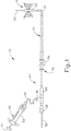
- FIG. 1 shows an exemplary dilation catheter system (10) that may be used to dilate the ostium of a paranasal sinus; or to dilate some other anatomical passageway (e.g., within the ear, nose, or throat, etc.).
- Dilation catheter system (10) of this example comprises a dilation catheter (20), a guide catheter (30), an inflator (40), and a guidewire (50).
- dilation catheter system (10) may be configured in accordance with at least some of the teachings of U.S. Patent Pub. No. 2011/0004057 .
- at least part of dilation catheter system (10) is configured similar to the Relieva ® Spin Balloon Sinuplasty TM System by Acclarent, Inc. of Menlo Park, California.
- the distal end (DE) of dilation catheter (20) includes an inflatable dilator (22).
- the proximal end (PE) of dilation catheter (20) includes a grip (24), which has a lateral port (26) and an open proximal end (28).
- a hollow-elongate shaft (18) extends distally from grip.
- Dilation catheter (20) includes a first lumen (not shown) formed within shaft (18) that provides fluid communication between lateral port (26) and the interior of dilator (22).
- Dilator catheter (20) also includes a second lumen (not shown) formed within shaft (18) that extends from open proximal end (28) to an open distal end that is distal to dilator (22).
- This second lumen is configured to slidably receive guidewire (50).
- the first and second lumens of dilator catheter (20) are fluidly isolated from each other.
- dilator (22) may be selectively inflated and deflated by communicating fluid along the first lumen via lateral port (26) while guidewire (50) is positioned within the second lumen.
- dilator catheter (20) is configured similar to the Relieva Ultirra TM Sinus Balloon Catheter by Acclarent, Inc. of Menlo Park, California.
- dilator catheter (20) is configured similar to the Relieva Solo Pro TM Sinus Balloon Catheter by Acclarent, Inc. of Menlo Park, California.
- Other suitable forms that dilator catheter (20) may take will be apparent to those of ordinary skill in the art in view of the teachings herein.
- guide catheter (30) of the present example includes a bent distal portion (32) at its distal end (DE) and a grip (34) at its proximal end (PE). Grip (34) has an open proximal end (36).
- Guide catheter (30) defines a lumen that is configured to slidably receive dilation catheter (20), such that guide catheter (30) may guide dilator (22) out through bent distal end (32).
- guide catheter (30) is configured similar to the Relieva Flex TM Sinus Guide Catheter by Acclarent, Inc. of Menlo Park, California. Other suitable forms that guide catheter (30) may take will be apparent to those of ordinary skill in the art in view of the teachings herein.
- inflator (40) of the present example comprises a barrel (42) that is configured to hold fluid and a plunger (44) that is configured to reciprocate relative to barrel (42) to selectively discharge fluid from (or draw fluid into) barrel (42).
- Barrel (42) is fluidly coupled with lateral port (26) via a flexible tube (46).
- inflator (40) is operable to add fluid to dilator (22) or withdraw fluid from dilator (22) by translating plunger (44) relative to barrel (42).
- the fluid communicated by inflator (40) comprises saline, though it should be understood that any other suitable fluid may be used.
- inflator (40) may be filled with fluid (e.g., saline, etc.).
- fluid e.g., saline, etc.
- the distal end of flexible tube (46) may be placed in a reservoir containing the fluid.
- Plunger (44) may then be retracted from a distal position to a proximal position to draw the fluid into barrel (42).
- Inflator (40) may then be held in an upright position, with the distal end of barrel (42) pointing upwardly, and plunger (44) may then be advanced to an intermediate or slightly distal position to purge any air from barrel (42).
- the distal end of flexible tube (46) may then be coupled with lateral port (26).
- inflator (40) is constructed and operable in accordance with at least some of the teachings of U.S. Pub. No. 2014/0074141, entitled “Inflator for Dilation of Anatomical Passageway," published March 13, 2014 .
- guidewire (50) of the present example comprises a coil (52) positioned about a core wire (54).
- An illumination fiber (56) extends along the interior of core wire (54) and terminates in an atraumatic lens (58).
- a connector (55) at the proximal end of guidewire (50) enables optical coupling between illumination fiber (56) and a light source (not shown).
- Illumination fiber (56) may comprise one or more optical fibers.
- Lens (58) is configured to project light when illumination fiber (56) is illuminated by the light source, such that illumination fiber (56) transmits light from the light source to the lens (58).
- the distal end of guidewire (50) is more flexible than the proximal end of guidewire (50).
- Guidewire (50) has a length enabling the distal end of guidewire (50) to be positioned distal to dilator (22) while the proximal end of guidewire (50) is positioned proximal to grip (24).
- Guidewire (50) may include indicia along at least part of its length (e.g., the proximal portion) to provide the operator with visual feedback indicating the depth of insertion of guidewire (50) relative to dilation catheter (20).
- guidewire (50) may be configured in accordance with at least some of the teachings of U.S. Pub. No. 2012/0078118 .
- guidewire (50) is configured similar to the Relieva Luma Sentry TM Sinus Illumination System by Acclarent, Inc. of Menlo Park, California. Other suitable forms that guidewire (50) may take will be apparent to those of ordinary skill in the art in view of the teachings herein.
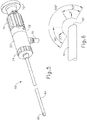
- an endoscope (60) may be used to provide visualization within an anatomical passageway (e.g., within the nasal cavity, etc.) during a process of using dilation catheter system (10).
- endoscope of the present example comprises a body (62) and a rigid shaft (64) extending distally from body (62).
- the distal end of shaft (64) includes a curved transparent window (66).
- a plurality of rod lenses and light transmitting fibers may extend along the length of shaft (64).
- a lens is positioned at the distal end of the rod lenses and a swing prism is positioned between the lens and window (66). The swing prism is pivotable about an axis that is transverse to the longitudinal axis of shaft (64).
- the swing prism defines a line of sight that pivots with the swing prism.
- the line of sight defines a viewing angle relative to the longitudinal axis of shaft (64). This line of sight may pivot from approximately 0 degrees to approximately 120 degrees, from approximately 10 degrees to approximately 90 degrees, or within any other suitable range.
- the swing prism and window (66) also provide a field of view spanning approximately 60 degrees (with the line of sight centered in the field of view). Thus, the field of view enables a viewing range spanning approximately 180 degrees, approximately 140 degrees, or any other range, based on the pivot range of the swing prism. Of course, all of these values are mere examples.
- Body (62) of the present example includes a light post (70), an eyepiece (72), a rotation dial (74), and a pivot dial (76).
- Light post (70) is in communication with the light transmitting fibers in shaft (64) and is configured to couple with a source of light, to thereby illuminate the site in the patient distal to window (66).
- Eyepiece (72) is configured to provide visualization of the view captured through window (66) via the optics of endoscope (60).
- a visualization system e.g., camera and display screen, etc.
- eyepiece (72) may be coupled with eyepiece (72) to provide visualization of the view captured through window (66) via the optics of endoscope (60).
- Rotation dial (74) is configured to rotate shaft (64) relative to body (62) about the longitudinal axis of shaft (64). It should be understood that such rotation may be carried out even while the swing prism is pivoted such that the line of sight is non-parallel with the longitudinal axis of shaft (64).
- Pivot dial (76) is coupled with the swing prism and is thereby operable to pivot the swing prism about the transverse pivot axis.
- Indicia (78) on body (62) provide visual feedback indicating the viewing angle.
- endoscope (60) may be configured in accordance with at least some of the teachings of U.S. Pub. No. 2010/0030031 .
- endoscope (60) is configured similar to the Acclarent Cyclops TM Multi-Angle Endoscope by Acclarent, Inc. of Menlo Park, California.
- Other suitable forms that endoscope (60) may take will be apparent to those of ordinary skill in the art in view of the teachings herein
- FIGS. 7A-7E show an exemplary method for using dilation catheter system (10) discussed above to dilate a sinus ostium (O) of a maxillary sinus (MS) of a patient. While the present example is being provided in the context of dilating a sinus ostium (O) of a maxillary sinus (MS), it should be understood that dilation catheter system (10) may be used in various other procedures.
- dilation catheter system (10) and variations thereof may be used to dilate a Eustachian tube, a larynx, a choana, a sphenoid sinus ostium, one or more openings associated with one or more ethmoid sinus air cells, the frontal recess, and/or other passageways associated with paranasal sinuses.
- dilation catheter system (10) may be used to dilate a Eustachian tube, a larynx, a choana, a sphenoid sinus ostium, one or more openings associated with one or more ethmoid sinus air cells, the frontal recess, and/or other passageways associated with paranasal sinuses.
- guide catheter (30) may be inserted transnasally and advanced through the nasal cavity (NC) to a position within or near the targeted anatomical passageway to be dilated, the sinus ostium (O), as shown in FIG. 7A .
- Inflatable dilator (22) and the distal end of guidewire (50) may be positioned within or proximal to bent distal end (32) of guide catheter (30) at this stage.
- This positioning of guide catheter (30) may be verified endoscopically with an endoscope such as endoscope (60) described above and/or by direct visualization, radiography, and/or by any other suitable method.
- the operator may advance guidewire (50) distally through guide catheter (30) such that a distal portion of the guidewire (50) passes through the ostium (O) of the maxillary sinus (MS) and into the cavity of the maxillary sinus (MS) as shown in FIGS. 7B and 7C .
- the operator may illuminate illumination fiber (56) and lens (58), which may provide transcutaneous illumination through the patient's face to enable the operator to visually confirm positioning of the distal end of guidewire (50) in the maxillary sinus (MS) with relative ease.
- dilation catheter (20) is advanced along guidewire (50) and through bent distal end (32) of guide catheter (30), with dilator (22) in a non-dilated state until dilator (22) is positioned within the ostium (O) of the maxillary sinus (MS) (or some other targeted anatomical passageway).
- dilator (22) may be inflated, thereby dilating the ostium (O), as shown in FIG. 7D .
- plunger (44) may be actuated to push saline from barrel (42) of inflator (40) through dilation catheter (20) into dilator (22).
- the transfer of fluid expands dilator (22) to an expanded state to open or dilate the ostium (O), such as by remodeling the bone, etc., forming ostium (O).
- dilator (22) may be inflated to a volume sized to achieve about 10 to about 12 atmospheres. Dilator (22) may be held at this volume for a few seconds to sufficiently open the ostium (O) (or other targeted anatomical passageway).
- Dilator (22) may then be returned to a non-expanded state by reversing plunger (44) of inflator (40) to bring the saline back to inflator (40).
- Dilator (22) may be repeatedly inflated and deflated in different ostia and/or other targeted anatomical passageways. Thereafter, dilation catheter (20), guidewire (50), and guide catheter (30) may be removed from the patient as shown in FIG. 7E .
- guide catheter (30) may be allowed to remain in place after removal of guidewire (50) and dilation catheter (20) and a lavage fluid, other substance, or one or more other devices (e.g ., lavage catheters, balloon catheters, cutting balloons, cutters, chompers, rotating cutters, rotating drills, rotating blades, sequential dilators, tapered dilators, punches, dissectors, burs, non-inflating mechanically expandable members, high frequency mechanical vibrators, dilating stents and radio frequency ablation devices, microwave ablation devices, laser devices, snares, biopsy tools, scopes, and devices that deliver diagnostic or therapeutic agents) may be passed through guide catheter (30) for further treatment of the condition.
- a lavage fluid, other substance, or one or more other devices e.g ., lavage catheters, balloon catheters, cutting balloons, cutters, chompers, rotating cutters, rotating drills, rotating blades, sequential dilators, tapered dilators, punches
- irrigation may be carried out in accordance with at least some of the teachings of U.S. Pat. No. 7,630,676, entitled “Methods, Devices and Systems for Treatment and/or Diagnosis of Disorders of the Ear, Nose and Throat," issued December 8, 2009 .
- An example of an irrigation catheter that may be fed through guide catheter (30) to reach the irrigation site after removal of dilation catheter (20) is the Relieva Vortex ® Sinus Irrigation Catheter by Acclarent, Inc. of Menlo Park, California.
- irrigation catheter that may be fed through guide catheter (30) to reach the irrigation site after removal of dilation catheter (20) is the Relieva Ultirra ® Sinus Irrigation Catheter by Acclarent, Inc. of Menlo Park, California.
- irrigation may be provided in the absence of a dilation procedure; and a dilation procedure may be completed without also including irrigation.
- FIG. 8 shows an exemplary IGS navigation system (100) whereby an ENT procedure may be performed using IGS.
- IGS navigation system (100) is used during a procedure where dilation catheter system (10) that may be used to dilate the ostium of a paranasal sinus; or to dilate some other anatomical passageway (e.g., within the ear, nose, or throat, etc.).
- dilation catheter system (10) that may be used to dilate the ostium of a paranasal sinus; or to dilate some other anatomical passageway (e.g., within the ear, nose, or throat, etc.).
- IGS navigation system (100) may be readily used in various other kinds of procedures.
- IGS navigation system (100) may be constructed and operable in accordance with at least some of the teachings of U.S. Pat. No. 8,702,626, entitled “Guidewires for Performing Image Guided Procedures,” issued April 22, 2014 ; U.S. Pat. No. 8,320,711, entitled “Anatomical Modeling from a 3-D Image and a Surface Mapping,” issued November 27, 2012 ; U.S. Pat. No. 8,190,389, entitled "Adapter for Attaching Electromagnetic Image Guidance Components to a Medical Device,” issued May 29, 2012 ; U.S. Pat. No.
- IGS navigation system (100) may be constructed and operable in accordance with at least some of the teachings of U.S. Pat. Pub. No. 2014/0364725, entitled “Systems and Methods for Performing Image Guided Procedures within the Ear, Nose, Throat and Paranasal Sinuses," published December 11, 2014 ; U.S. Pat. Pub. No. 2014/0200444, entitled "Guidewires for Performing Image Guided Procedures," published July 17, 2014 ; U.S. Pat. Pub. No.
- 2012/0245456 entitled “Adapter for Attaching Electromagnetic Image Guidance Components to a Medical Device," published September 27, 2012 ; U.S. Pat. Pub. No. 2011/0060214, entitled “Systems and Methods for Performing Image Guided Procedures within the Ear, Nose, Throat and Paranasal Sinuses," published March 10, 2011 ; U.S. Pat. Pub. No. 2008/0281156, entitled “Methods and Apparatus for Treating Disorders of the Ear Nose and Throat,” published November 13, 2008 ; and U.S. Pat. Pub. No. 2007/0208252, entitled “Systems and Methods for Performing Image Guided Procedures within the Ear, Nose, Throat and Paranasal Sinuses,” published September 6, 2007 .
- IGS navigation system (100) of the present example comprises a set of magnetic field generators (122).
- field generators (122) are fixed to the head of the patient.
- field generators (122) are incorporated into a frame (120), which is clamped to the head of the patient. While field generators (122) are secured to the head of the patient in this example, it should be understood that field generators (122) may instead be positioned at various other suitable locations and on various other suitable structures.
- field generators (122) may be mounted on an independent structure that is fixed to a table or chair on which the patient is positioned, on a floor-mounted stand that has been locked in position relative to the head of the patient, and/or at any other suitable location(s) and/or on any other suitable structure(s).
- Field generators (122) are operable to generate an electromagnetic field around the head of the patient.
- field generators (122) are operated so as to transmit alternating magnetic fields of different frequencies into a region in proximity to frame (120).
- Field generators (122) thereby enable tracking of the position of a navigation guidewire (130) that is inserted into a nasal sinus of the patient and in other locations within the patient's head.
- Various suitable components that may be used to form and drive field generators (122) will be apparent to those of ordinary skill in the art in view of the teachings herein.
- Navigation guidewire (130) may be used as a substitute for guidewire (50) described above, and may include a sensor (not shown) that is responsive to movement within the fields generated by field generators (122).
- signals generated by the sensor of navigation guidewire (130) may be processed by processor (110) to determine the three-dimensional location of navigation guidewire (130) within the patient.
- processor (110) may be processed by processor (110) to determine the three-dimensional location of navigation guidewire (130) within the patient.
- navigation guidewire (130) may facilitate navigation of instrumentation of dilation catheter system (10) within the patient during performance of a procedure to dilate the ostium of a paranasal sinus; or to dilate some other anatomical passageway (e.g., within the ear, nose, or throat, etc.).
- other components of dilation catheter system (10) may incorporate a sensor like the sensor of navigation guidewire (130), including but not limited to the exemplary alternative dilation catheter (200) described below.
- IGS navigation system (100) of the present example further comprises a processor (110), which controls field generators (122) and other elements of IGS navigation system (100).
- Processor (110) comprises a processing unit communicating with one or more memories.
- Processor (110) of the present example is mounted in a console (116), which comprises operating controls (112) that include a keypad and/or a pointing device such as a mouse or trackball. A physician uses operating controls (112) to interact with processor (110) while performing the surgical procedure.
- Console (116) also connects to other elements of system (100). For instance, as shown in FIG. 8 a coupling unit (132) is secured to the proximal end of navigation guidewire (130). Coupling unit (132) of this example is configured to provide wireless communication of data and other signals between console (116) and navigation guidewire (130). In some versions, coupling unit (132) simply communicates data or other signals from navigation guidewire (130) to console (116) uni-directionally, without also communicating data or other signals from console (116). In some other versions, coupling unit (132) provides bidirectional communication of data or other signals between navigation guidewire (130) to console (116).
- coupling unit (132) of the present example couples with console (116) wirelessly
- some other versions may provide wired coupling between coupling unit (132) and console (116).
- Various other suitable features and functionality that may be incorporated into coupling unit (132) will be apparent to those of ordinary skill in the art in view of the teachings herein.
- Processor (110) uses software stored in a memory of processor (110) to calibrate and operate system (100). Such operation includes driving field generators (122), processing data from navigational guidewire (130), processing data from operating controls (112), and driving display screen (114).
- the software may be downloaded to processor (110) in electronic form, over a network, for example, or it may, alternatively or additionally, be provided and/or stored on non-transitory tangible media, such as magnetic, optical, or electronic memory.
- Processor (110) is further operable to provide video in real time via display screen (114), showing the position of the distal end of navigational guidewire (130) in relation to a video camera image of the patient's head, a CT scan image of the patient's head, and/or a computer generated three-dimensional model of the anatomy within and adjacent to the patient's nasal cavity.
- Display screen (114) may display such images simultaneously and/or superimposed on each other.
- display screen (114) may display such images during the surgical procedure.
- Such displayed images may also include graphical representations of instruments that are inserted in the patient's head, such as navigational guidewire (130), such that the operator may view the virtual rendering of the instrument at its actual location in real time.
- display screen (114) may provide images in accordance with at least some of the teachings of U.S. Pub. No. 2016/0008083, entitled “Guidewire Navigation for Sinuplasty,” published January 14, 2016 .
- the endoscopic image may also be provided on display screen (114). The images provided through display screen (114) may help guide the operator in maneuvering and otherwise manipulating instruments within the patient's head.
- navigational guidewire (130) includes one or more coils at the distal end of navigational guidewire (130).
- a coil serves as a sensor as referred to above.
- processor (110) executes an algorithm to calculate location coordinates of the distal end of navigational guidewire (130) from the position related signals of the coil(s) in navigational guidewire (130).
- navigational guidewire (130) is used to generate a three-dimensional model of the anatomy within and adjacent to the patient's nasal cavity; in addition to being used to provide navigation for dilation catheter system (100) within the patient's nasal cavity.
- any other suitable device may be used to generate a three-dimensional model of the anatomy within and adjacent to the patient's nasal cavity before navigational guidewire (130) is used to provide navigation for dilation catheter system (100) within the patient's nasal cavity.
- a model of this anatomy may be generated in accordance with at least some of the teachings of U.S. Pat. App. No. 14/825,551, entitled “System and Method to Map Structures of Nasal Cavity," filed August 13, 2015 , published as U.S. Pub.
- Console (116) may thus render images of at least a portion of the model via display screen (114) and further render real-time video images of the position of navigational guidewire (130) in relation to the model via display screen (114).
- tissue of a dilated anatomical passageway may become diseased, may become swollen, may naturally grow, or may develop some other condition that might adversely impact the patency of the dilated passageway. If this occurs, the adverse impact of the patency on the dilated passageway might frustrate the purpose of the dilation procedure.
- a dilated anatomical passageway e.g., sinus ostium or other passageway associated with drainage of a paranasal sinus, a Eustachian tube, etc.
- the tissue of a dilated anatomical passageway may become diseased, may become swollen, may naturally grow, or may develop some other condition that might adversely impact the patency of the dilated passageway. If this occurs, the adverse impact of the patency on the dilated passageway might frustrate the purpose of the dilation procedure.
- applying RF energy to the tissue of the dilated anatomical passageway may reduce the likelihood that the tissue of the dilated anatomical passageway will become diseased, become swollen, grow, or develop some other condition that might adversely impact the patency of the dilated passageway.
- the RF energy may ablate the tissue and thereby generate a scar that will not become diseased, become swollen, grow, or develop some other condition that might adversely impact the patency of the dilated passageway.
- the RF-generated scar may help maintain patency of the dilated anatomical passageway.
- the RF ablation may immediately stop bleeding that might otherwise occur as a result of a dilation procedure.
- drugs or some other media e.g., antibiotics, etc.
- drugs may be applied in conjunction with the RF energy.
- the following description relates to an exemplary device that may be used to apply RF energy, and in some cases drugs and/or other media, to the tissue of an anatomical passageway before, during, and/or after a dilation procedure.
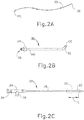
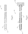
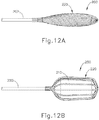
- FIGS. 10-12B show an exemplary alternative dilation catheter (200). It should be understood that dilation catheter (200) may be used with dilation catheter system (10) in place of dilation catheter (20). Other suitable devices with which dilation catheter (200) may be used will be apparent to those of ordinary skill in the art in view of the teachings herein.
- Dilation catheter (200) of this example comprises a shaft (202), an inflatable dilator (210), and a wire assembly (220). Dilator (210) and wire assembly (220) are both fixedly secured to shaft (202).
- Dilation catheter (200) of the present example is also in communication with an inflator (204), an RF power source (206), and a navigation system (208).
- Dilator (210) of the present example is substantially identical to dilator (22) described above, such that dilator (210) is operable to transition between a non-expanded configuration ( FIG. 12A ) and an expanded configuration ( FIG. 12B ).
- dilator (210) is in fluid communication with an inflator (204).
- Inflator (204) may be constructed and operable just like inflator (40) described above; or may have any other suitable configuration.
- saline or any other suitable fluid may be used to selectively inflate dilator (210).
- dilator (210) is formed of a non-compliant or non-extensible material, such that dilator (210) will provide a substantially consistent inflated configuration.
- Wire assembly (220) is positioned coaxially about dilator (210), such that wire assembly (220) encompasses dilator (210).
- the proximal end of wire assembly (220) is proximal to the proximal end of dilator (210); and the distal end of wire assembly (220) is distal to the distal end of dilator (210).
- Wire assembly (220) comprises a set of wires (222, 224, 226).
- wires (222, 224, 226) may be formed of nitinol, silver, and/or any other electrically conductive material (or combination of materials).
- Wires (222, 224) are electrically coupled with RF power source (206).
- RF power source (206) is operable to provide a positive charge to wires (222) and a negative charge to wires (224). It should therefore be understood that wires (222, 224) may cooperate to apply bipolar RF energy to tissue that contacts wires (222, 224). It should also be understood that this bipolar RF energy may scar the tissue as noted above.
- Wires (226) are coated with a non-conductive coating in this example, such that wires (226) are electrically non-conductive.
- a non-conductive coating such that wires (226) are electrically non-conductive.
- Various suitable kinds of non-conductive coatings that may be applied to wires (226) will be apparent to those of ordinary skill in the art in view of the teachings herein.
- wires (226) are interposed between wires (222, 224), and wires (222, 224) alternate in their positioning between adjacent wires (226).
- the distal and proximal ends of wires (222, 224, 226) include additional non-conductive coating (230) in this example.
- this additional non-conductive coating (230) may prevent short circuits from forming between the distal ends of wires (222, 224) or between the proximal ends of wires (222, 224). While an additional non-conductive coating (230) is applied to the distal and proximal ends of wires (226) in this example, it should be understood that an additional non-conductive coating (230) is not necessarily required for wires (226), particularly since the entire length of each wire (226) is already coated with a non-conductive coating in this example.
- wire assembly (220) is operable to expand and contract with dilator (210).
- wire assembly (220) is resiliently biased to contract to the non-expanded state shown in FIG. 12A ; yet wire assembly (220) is also flexible enough to expand with dilator (210) to achieve the expanded state shown in FIG. 12B , without substantially impeding the expansion of dilator (210).
- the interior lengths of wires (222, 224, 226) are not bonded to dilator (210) it this example, such that wires (222, 224, 226) may slide along the exterior of dilator (210) as dilator (210) transitions between the expanded and non-expanded states.
- wire assembly (220) is resiliently biased to assume a twisted configuration (i.e., twisted about the longitudinal axis of dilation catheter (200)) in the non-expanded state.
- dilation catheter (200) is positioned such that dilator (210) and wire assembly (220) are located within a targeted anatomical passageway. Dilator (210) is in a non-expanded state ( FIG. 12A ) during such positioning.
- the targeted anatomical passageway may comprise an ostium of a paranasal sinus, some other drainage passageway associated with a paranasal sinus, or a Eustachian tube.
- dilation catheter (200) may be positioned within the targeted anatomical passageway by using guide catheter (30), guidewire (50), and/or any other suitable instrumentation.
- guide catheter (30), guidewire (50), and/or any other suitable instrumentation may be positioned such that a paranasal sinus, some other drainage passageway associated with a paranasal sinus, or a Eustachian tube.
- dilation catheter (200) may be positioned within the targeted anatomical passageway by using guide catheter (30), guidewire (50), and/or any other suitable instrumentation.
- inflator (204) may be activated to expand dilator (210) to the expanded state ( FIG. 12B ).
- wire assembly (220) expands with dilator (210). The expansion of dilator (210) and wire assembly (220) will dilate the targeted anatomical passageway.
- RF power source (206) is activated to apply bipolar RF energy via wires (222, 224) to the tissue defining the targeted anatomical passageway. This RF energy generates a scar at the adjacent tissue.
- the operator may alternatingly transition dilator (210) and wire assembly (220) between the expanded and non-expended state several times, applying RF energy any suitable number times when dilator (210) and wire assembly (220) are expanded.
- the operator may then remove dilation catheter (200) from the patient with dilator (210) and wire assembly (220) in the non-expanded state, resulting in a dilated anatomical passageway with a scar eventually forming at the tissue defining the dilated anatomical passageway.
- dilator (210) and/or wire assembly (220) is coated with a drug and/or other media (e.g., antibiotic, etc.), such that dilator (210) and/or wire assembly (220) may apply such a drug and/or other media to the tissue.
- a drug and/or other media e.g., antibiotic, etc.
- the drug and/or other media may be delivered to the tissue as dilator (210) is dilating the targeted anatomical passageway.
- the RF energy may be used to assist in the delivery of the drug and/or other media to the tissue.
- wires (222, 224) may be used to transmit high amplitude pulses to provide electroporation in the tissue, which may result in faster and more effective delivery of the drug and/or other media to the tissue.
- RF power source (206) and wires (222, 224) may be used to provide such electroporation will be apparent to those of ordinary skill in the art in view of the teachings herein. It should be understood that this aspect of electroporation is merely optional. Likewise, the aspect of delivering a drug or other media to the tissue is merely optional.
- dilation catheter (200) is also in communication with navigation system (208).
- Navigation system (208) of this example may be configured and operable just like IGS navigation system (100) described above.
- dilation catheter (200) of the present example comprises a sensor (250) that is configured to cooperate with navigation system (208) to generate position related data through navigation system (208), thereby enabling the operator to determine the precise location of dilation catheter (200) within the patient as described above in the context of IGS navigation system (100). While sensor (250) is shown as being located on wire (222), it should be understood that sensor (250) may be positioned elsewhere on dilation catheter (200).
- sensor (250) may be in the form of a coil that generates an electrical current when dilation catheter (200) is moved within an electromagnetic field, and this electrical current may be processed by navigation system (208) to determine the location of sensor (250) within a three-dimensional space as described above.
- dilation catheter (200) includes a sensor (250)
- sensor (250) may be used in various anatomical locations without wire assembly (220) necessarily applying RF energy within such anatomical locations.
- the navigational functionality provided by sensor (250) may be utilized completely independently of the RF ablation functionality provided by wire assembly (220).
- sensor (250) and navigation system (208) are merely optional, such that sensor (250) and navigation system (208) may be omitted if desired.
- any of the examples described herein may include various other features in addition to or in lieu of those described above.
- any of the examples described herein may also include one or more of the various features disclosed in any of the various references cited herein.
- Versions of the devices disclosed herein can be designed to be disposed of after a single use, or they can be designed to be used multiple times. Versions may, in either or both cases, be reconditioned for reuse after at least one use. Reconditioning may include any combination of the steps of disassembly of the device, followed by cleaning or replacement of particular pieces, and subsequent reassembly. In particular, versions of the device may be disassembled, and any number of the particular pieces or parts of the device may be selectively replaced or removed in any combination. Upon cleaning and/or replacement of particular parts, versions of the device may be reassembled for subsequent use either at a reconditioning facility, or by a surgical team immediately prior to a surgical procedure.
- reconditioning of a device may utilize a variety of techniques for disassembly, cleaning/replacement, and reassembly. Use of such techniques, and the resulting reconditioned device, are all within the scope of the present application.
- versions described herein may be processed before surgery.
- a new or used instrument may be obtained and if necessary cleaned.
- the instrument may then be sterilized.
- the instrument is placed in a closed and sealed container, such as a plastic or TYVEK bag.
- the container and instrument may then be placed in a field of radiation that can penetrate the container, such as gamma radiation, x-rays, or high-energy electrons.
- the radiation may kill bacteria on the instrument and in the container.
- the sterilized instrument may then be stored in the sterile container.
- the sealed container may keep the instrument sterile until it is opened in a surgical facility.
- a device may also be sterilized using any other technique known in the art, including but not limited to beta or gamma radiation, ethylene oxide, or steam.
Landscapes
- Health & Medical Sciences (AREA)
- Life Sciences & Earth Sciences (AREA)
- Surgery (AREA)
- Engineering & Computer Science (AREA)
- Heart & Thoracic Surgery (AREA)
- Biomedical Technology (AREA)
- Animal Behavior & Ethology (AREA)
- General Health & Medical Sciences (AREA)
- Public Health (AREA)
- Veterinary Medicine (AREA)
- Molecular Biology (AREA)
- Nuclear Medicine, Radiotherapy & Molecular Imaging (AREA)
- Medical Informatics (AREA)
- Physics & Mathematics (AREA)
- Otolaryngology (AREA)
- Biophysics (AREA)
- Optics & Photonics (AREA)
- Radiology & Medical Imaging (AREA)
- Pathology (AREA)
- Plasma & Fusion (AREA)
- Anesthesiology (AREA)
- Hematology (AREA)
- Cardiology (AREA)
- Vascular Medicine (AREA)
- Pulmonology (AREA)
- Child & Adolescent Psychology (AREA)
- Robotics (AREA)
- Surgical Instruments (AREA)
- Endoscopes (AREA)
- Media Introduction/Drainage Providing Device (AREA)
Claims (15)
- Vorrichtung (200), umfassend:(a) einen Schaft (202), der ein proximales Ende und ein distales Ende aufweist;(b) einen expandierbaren Dilator (210), der sich an dem distalen Ende des Schafts befindet, wobei der expandierbare Dilator funktional ist, um zwischen einer nicht-expandierten Konfiguration und einer expandierten Konfiguration zu wechseln, wobei der expandierbare Dilator ein proximales Ende und ein distales Ende aufweist; und(c) eine Drahtanordnung (220), wobei die Drahtanordnung um eine Außenseite des expandierbaren Dilators herum angeordnet ist, wobei die Drahtanordnung ein proximales Ende und ein distales Ende aufweist, wobei das proximale Ende der Drahtanordnung sich proximal des proximalen Endes des expandierbaren Dilators befindet, wobei das distale Ende der Drahtanordnung sich distal des distalen Endes des Dilators befindet, wobei die Drahtanordnung ausgestaltet ist, um bipolare HF-Energie auf Gewebe anzuwenden,wobei die Drahtanordnung eine erste Vielzahl von Drähten und eine zweite Vielzahl von Drähten (222, 224) umfasst, wobei die erste Vielzahl von Drähten ausgestaltet ist, um einen ersten Pol der HF-Energie bereitzustellen, wobei die zweite Vielzahl der Drähte ausgestaltet ist, um einen zweiten Pol der HF-Energie bereitzustellen,
dadurch gekennzeichnet, dass die Drahtanordnung des Weiteren eine dritte Vielzahl von Drähten (226) umfasst, wobei die dritte Vielzahl von Drähten eine nicht-leitfähige Beschichtung (230) einschließt, und wobei die Drähte der dritten Vielzahl von Drähten winklig zwischen den Drähten der ersten und der zweiten Vielzahl von Drähten angeordnet sind. - Vorrichtung nach Anspruch 1, wobei die Drahtanordnung des Weiteren eine proximale Region einschließlich des proximalen Endes der Drahtanordnung, eine distale Region einschließlich des distalen Endes der Drahtanordnung und eine Zwischenregion einschließt, wobei die Zwischenregion elektrisch leitfähige exponierte Drähte einschließt.
- Vorrichtung nach Anspruch 2, wobei die proximale Region eine elektrisch isolierende Beschichtung (230) einschließt, wobei die distale Region eine elektrisch isolierende Beschichtung (230) einschließt.
- Vorrichtung nach Anspruch 1, wobei die Drahtanordnung ausgestaltet ist, um mit dem expandierbaren Dilator zwischen einer nicht-expandierten Konfiguration und einer expandierten Konfiguration zu wechseln.
- Vorrichtung nach Anspruch 4, wobei die Drahtanordnung elastisch zu der nicht-expandierten Konfiguration vorgespannt ist.
- Vorrichtung nach Anspruch 1, wobei die Drahtanordnung Drähte einschließt, die mindestens teilweise aus Nitinol gebildet sind.
- Vorrichtung nach Anspruch 1, wobei die Drahtanordnung Drähte einschließt, die mindestens teilweise aus Silber gebildet sind.
- Vorrichtung nach Anspruch 1, des Weiteren umfassend ein Arzneimittel oder andere therapeutische Substanz, das bzw. die auf ein oder mehrere von dem expandierbaren Dilator oder der Drahtanordnung aufgebracht ist.
- Vorrichtung nach Anspruch 8, des Weiteren umfassend eine HF-Energiequelle (206), die mit der Drahtanordnung gekoppelt ist, wobei die HF-Energiequelle ausgestaltet ist, um Pulse von HF-Energie über die Drahtanordnung anzuwenden, um dadurch Elektroporation in Gewebe bereitzustellen.
- Vorrichtung nach Anspruch 1, des Weiteren umfassend einen Sensor (250), wobei der Sensor ausgestaltet ist, um mit einem Navigationssystem (208) zusammenzuarbeiten, um Daten zu generieren, die eine Position von einem oder beiden von dem expandierbaren Dilator oder der Drahtanordnung innerhalb eines Patienten angeben, wobei der Sensor gegebenenfalls in der Drahtanordnung lokalisiert ist.
- Vorrichtung nach Anspruch 1, wobei der expandierbare Dilator einen Ballon umfasst, der aus einem nicht-nachgiebigen Material gebildet ist.
- Vorrichtung nach Anspruch 1, des Weiteren umfassend eine Fluidquelle in Fluidkommunikation mit dem expandierbaren Dilator.
- Vorrichtung nach Anspruch 1, wobei:mindestens ein Anteil jedes Drahtes von der ersten Vielzahl der Drähte eine exponierte, elektrisch leitfähige Oberfläche einschließt, undmindestens ein Anteil jedes Drahtes von der zweiten Vielzahl der Drähte eine exponierte, elektrisch leitfähige Oberfläche einschließt,die Vorrichtung des Weiteren eine HF-Leistungsquelle in Kommunikation mit der Drahtanordnung umfasst.
- Vorrichtung nach Anspruch 13, wobei die erste und die zweite Vielzahl von Drähten in einer alternierenden, winklig beabstandeten Gruppierung angeordnet ist.
- Vorrichtung nach Anspruch 13, wobei jeder Draht von der dritten Vielzahl der Drähte mit der elektrisch nicht-leitfähigen Beschichtung über die volle Länge jedes Drahtes von der dritten Vielzahl von Drähten beschichtet ist.
Priority Applications (1)
| Application Number | Priority Date | Filing Date | Title |
|---|---|---|---|
| EP21204198.2A EP3967257A1 (de) | 2016-10-18 | 2017-10-09 | Dilatationsballon mit rf-energiefreisetzung |
Applications Claiming Priority (2)
| Application Number | Priority Date | Filing Date | Title |
|---|---|---|---|
| US15/296,274 US10485609B2 (en) | 2016-10-18 | 2016-10-18 | Dilation balloon with RF energy delivery feature |
| PCT/US2017/055691 WO2018075273A1 (en) | 2016-10-18 | 2017-10-09 | Dilation balloon with rf energy delivery feature |
Related Child Applications (2)
| Application Number | Title | Priority Date | Filing Date |
|---|---|---|---|
| EP21204198.2A Division EP3967257A1 (de) | 2016-10-18 | 2017-10-09 | Dilatationsballon mit rf-energiefreisetzung |
| EP21204198.2A Division-Into EP3967257A1 (de) | 2016-10-18 | 2017-10-09 | Dilatationsballon mit rf-energiefreisetzung |
Publications (2)
| Publication Number | Publication Date |
|---|---|
| EP3528731A1 EP3528731A1 (de) | 2019-08-28 |
| EP3528731B1 true EP3528731B1 (de) | 2021-12-01 |
Family
ID=60164839
Family Applications (2)
| Application Number | Title | Priority Date | Filing Date |
|---|---|---|---|
| EP21204198.2A Withdrawn EP3967257A1 (de) | 2016-10-18 | 2017-10-09 | Dilatationsballon mit rf-energiefreisetzung |
| EP17788396.4A Not-in-force EP3528731B1 (de) | 2016-10-18 | 2017-10-09 | Dilatationsballon mit rf-energiefreisetzung |
Family Applications Before (1)
| Application Number | Title | Priority Date | Filing Date |
|---|---|---|---|
| EP21204198.2A Withdrawn EP3967257A1 (de) | 2016-10-18 | 2017-10-09 | Dilatationsballon mit rf-energiefreisetzung |
Country Status (6)
| Country | Link |
|---|---|
| US (1) | US10485609B2 (de) |
| EP (2) | EP3967257A1 (de) |
| JP (1) | JP7330889B2 (de) |
| KR (1) | KR20190072588A (de) |
| CN (1) | CN109843203B (de) |
| WO (1) | WO2018075273A1 (de) |
Families Citing this family (23)
| Publication number | Priority date | Publication date | Assignee | Title |
|---|---|---|---|---|
| US10322269B1 (en) | 2015-01-19 | 2019-06-18 | Dalent, LLC | Dilator device |
| US20190374129A1 (en) * | 2018-06-07 | 2019-12-12 | Acclarent, Inc. | Endoscope with integral navigation sensor |
| US11622805B2 (en) * | 2018-06-08 | 2023-04-11 | Acclarent, Inc. | Apparatus and method for performing vidian neurectomy procedure |
| US11147629B2 (en) | 2018-06-08 | 2021-10-19 | Acclarent, Inc. | Surgical navigation system with automatically driven endoscope |
| US11154357B2 (en) * | 2018-06-21 | 2021-10-26 | Biosense Webster (Israel) Ltd. | Electrical grounding feature for irrigation fluid path in catheter assembly |
| US11484366B2 (en) * | 2018-11-29 | 2022-11-01 | Acclarent, Inc. | Adapter assembly to enable navigation for ENT instruments |
| US11583393B2 (en) * | 2018-12-05 | 2023-02-21 | Acclarent, Inc. | Apparatus and method to maintain patency of dilated anatomical opening |
| US11419623B2 (en) * | 2018-12-12 | 2022-08-23 | Acclarent, Inc. | Sinuplasty instrument with moveable navigation sensor |
| US11395906B2 (en) * | 2018-12-12 | 2022-07-26 | Acclarent, Inc. | Combined sinuplasty and seeker instrument with navigation and illumination modalities |
| US11786296B2 (en) | 2019-02-15 | 2023-10-17 | Accularent, Inc. | Instrument for endoscopic posterior nasal nerve ablation |
| US12011213B2 (en) * | 2019-03-29 | 2024-06-18 | Acclarent, Inc. | System and method for treating epistaxis |
| US11712548B2 (en) * | 2019-03-29 | 2023-08-01 | Acclarent, Inc. | Eustachian tube dilation catheter with depth indicia |
| US11534235B2 (en) | 2019-04-04 | 2022-12-27 | Acclarent, Inc. | Needle instrument for posterior nasal neurectomy ablation |
| EP3982851A4 (de) | 2019-06-11 | 2023-08-16 | Dalent, LLC | Ballondilatationsvorrichtung |
| US12207858B2 (en) | 2020-06-24 | 2025-01-28 | Acclarent, Inc. | Apparatus and method for ablating Eustachian tube |
| US20220087739A1 (en) * | 2020-09-18 | 2022-03-24 | Acclarent, Inc. | Ent instrument with expandable ablation feature |
| WO2022231726A1 (en) | 2021-04-26 | 2022-11-03 | Pulse Biosciences, Inc. | Circumferential ablation devices and methods |
| US12446944B2 (en) | 2021-04-26 | 2025-10-21 | Pulse Biosciences, Inc. | Mapping and ablation applicators |
| US12564440B2 (en) | 2021-04-26 | 2026-03-03 | Pulse Biosciences, Inc. | Multi-strut ablation and sensing catheter devices and methods |
| WO2023059507A1 (en) * | 2021-10-04 | 2023-04-13 | Boston Scientific Scimed Inc. | Cardiac ablation catheters with integrated navigation sensors |
| WO2023194970A1 (en) * | 2022-04-08 | 2023-10-12 | Acclarent, Inc. | Intranasal balloon compression for treatment of chronic rhinitis |
| WO2024189454A1 (en) * | 2023-03-10 | 2024-09-19 | Acclarent, Inc. | Intranasal balloon compression for treatment of chronic rhinitis |
| WO2025155617A1 (en) * | 2024-01-16 | 2025-07-24 | Aventix Medical Inc. | Pulsed field electroporation systems and methods |
Family Cites Families (33)
| Publication number | Priority date | Publication date | Assignee | Title |
|---|---|---|---|---|
| US4362150A (en) * | 1980-09-10 | 1982-12-07 | Kontron Cardiovascular Inc. | Percutaneous intra-aortic balloon apparatus |
| US6033397A (en) * | 1996-03-05 | 2000-03-07 | Vnus Medical Technologies, Inc. | Method and apparatus for treating esophageal varices |
| US6322559B1 (en) * | 1998-07-06 | 2001-11-27 | Vnus Medical Technologies, Inc. | Electrode catheter having coil structure |
| US6036689A (en) * | 1998-09-24 | 2000-03-14 | Tu; Lily Chen | Ablation device for treating atherosclerotic tissues |
| US6050995A (en) * | 1998-09-24 | 2000-04-18 | Scimed Lifesystems, Inc. | Polypectomy snare with multiple bipolar electrodes |
| ATE301970T1 (de) * | 2001-09-28 | 2005-09-15 | Shutaro Satake | Mit radiofrequenz arbeitender thermischer ballonkatheter |
| US7462175B2 (en) | 2004-04-21 | 2008-12-09 | Acclarent, Inc. | Devices, systems and methods for treating disorders of the ear, nose and throat |
| US20070208252A1 (en) | 2004-04-21 | 2007-09-06 | Acclarent, Inc. | Systems and methods for performing image guided procedures within the ear, nose, throat and paranasal sinuses |
| US8702626B1 (en) | 2004-04-21 | 2014-04-22 | Acclarent, Inc. | Guidewires for performing image guided procedures |
| US7720521B2 (en) | 2004-04-21 | 2010-05-18 | Acclarent, Inc. | Methods and devices for performing procedures within the ear, nose, throat and paranasal sinuses |
| US20110004057A1 (en) | 2004-04-21 | 2011-01-06 | Acclarent, Inc. | Systems and methods for transnasal dilation of passageways in the ear, nose or throat |
| US20060063973A1 (en) | 2004-04-21 | 2006-03-23 | Acclarent, Inc. | Methods and apparatus for treating disorders of the ear, nose and throat |
| JP2008526463A (ja) * | 2005-01-18 | 2008-07-24 | エス・ディー・エム・エイチ・プロプライエタリー・リミテッド | 球形の焼灼パターンを使用して生物学的組織を熱焼灼する装置及び方法 |
| US8190389B2 (en) | 2006-05-17 | 2012-05-29 | Acclarent, Inc. | Adapter for attaching electromagnetic image guidance components to a medical device |
| US7630676B2 (en) | 2006-12-06 | 2009-12-08 | Xerox Corporation | Self-loading belt fusing apparatus |
| US20080183128A1 (en) | 2007-01-24 | 2008-07-31 | John Morriss | Methods, devices and systems for treatment and/or diagnosis of disorders of the ear, nose and throat |
| CN101178041A (zh) * | 2007-11-22 | 2008-05-14 | 孙靖茗 | 一种油温加热线 |
| US8320711B2 (en) | 2007-12-05 | 2012-11-27 | Biosense Webster, Inc. | Anatomical modeling from a 3-D image and a surface mapping |
| WO2009121009A2 (en) | 2008-03-27 | 2009-10-01 | The Regents Of The University Of California | Irreversible electroporation device for use in attenuating neointimal |
| US20100030031A1 (en) | 2008-07-30 | 2010-02-04 | Acclarent, Inc. | Swing prism endoscope |
| CA2797130A1 (en) * | 2010-05-12 | 2011-11-17 | Shifamed Holdings, Llc | Low profile electrode assembly |
| US9155492B2 (en) | 2010-09-24 | 2015-10-13 | Acclarent, Inc. | Sinus illumination lightwire device |
| US8900227B2 (en) | 2011-01-06 | 2014-12-02 | Karen Stierman | Sinus ablation devices, methods, and systems |
| SG10201607576PA (en) | 2011-06-14 | 2016-11-29 | Aerin Medical Inc | Devices for treating nasal airways |
| CN104768480B (zh) | 2012-09-10 | 2017-12-08 | 阿克拉伦特公司 | 用于扩张解剖通道的压送器 |
| JP5789576B2 (ja) * | 2012-09-14 | 2015-10-07 | 日立オートモティブシステムズ株式会社 | 電力変換装置 |
| US10499980B2 (en) * | 2013-03-14 | 2019-12-10 | Spiration, Inc. | Flexible RF ablation needle |
| WO2014195933A1 (en) * | 2013-06-05 | 2014-12-11 | Tel Hashomer Medical Research Infrastructure And Services Ltd. | Myocardial ablation by irreversible electroporation |
| US20150045787A1 (en) * | 2013-08-09 | 2015-02-12 | Medtronic-Xomed, Inc. | Electrosurgical device and method |
| US10463242B2 (en) | 2014-07-09 | 2019-11-05 | Acclarent, Inc. | Guidewire navigation for sinuplasty |
| US9314208B1 (en) * | 2014-10-28 | 2016-04-19 | Biosense Webster (Israel) Ltd. | Basket catheter with microelectrode array distal tip |
| US10362965B2 (en) | 2015-04-22 | 2019-07-30 | Acclarent, Inc. | System and method to map structures of nasal cavity |
| US11026746B2 (en) * | 2015-05-12 | 2021-06-08 | National University Of Ireland, Galway | Devices for therapeutic nasal neuromodulation and associated methods and systems |
-
2016
- 2016-10-18 US US15/296,274 patent/US10485609B2/en not_active Expired - Fee Related
-
2017
- 2017-10-09 WO PCT/US2017/055691 patent/WO2018075273A1/en not_active Ceased
- 2017-10-09 KR KR1020197014183A patent/KR20190072588A/ko not_active Withdrawn
- 2017-10-09 EP EP21204198.2A patent/EP3967257A1/de not_active Withdrawn
- 2017-10-09 EP EP17788396.4A patent/EP3528731B1/de not_active Not-in-force
- 2017-10-09 CN CN201780064461.7A patent/CN109843203B/zh not_active Expired - Fee Related
- 2017-10-09 JP JP2019541667A patent/JP7330889B2/ja active Active
Also Published As
| Publication number | Publication date |
|---|---|
| EP3967257A1 (de) | 2022-03-16 |
| US10485609B2 (en) | 2019-11-26 |
| KR20190072588A (ko) | 2019-06-25 |
| WO2018075273A1 (en) | 2018-04-26 |
| CN109843203B (zh) | 2022-09-13 |
| EP3528731A1 (de) | 2019-08-28 |
| CN109843203A (zh) | 2019-06-04 |
| JP2019531174A (ja) | 2019-10-31 |
| JP7330889B2 (ja) | 2023-08-22 |
| US20180104001A1 (en) | 2018-04-19 |
Similar Documents
| Publication | Publication Date | Title |
|---|---|---|
| US10485609B2 (en) | Dilation balloon with RF energy delivery feature | |
| JP7263460B2 (ja) | ナビゲーションセンサを伴うガイドワイヤ | |
| US10610308B2 (en) | Navigation guidewire with interlocked coils | |
| EP3367932B1 (de) | System zur navigation chirurgischer instrumente | |
| US10857333B2 (en) | Guidewire with integral expandable dilator | |
| EP3678561B1 (de) | Sensorgeführtes instrument mit penetrierungsmerkmal | |
| US20180264237A1 (en) | Navigation guidewire with shielded sensor coil | |
| EP3678729B1 (de) | Führungsdrahtvorrichtung mit verdrilltem kerndraht | |
| US20190184142A1 (en) | Guidewire assembly with offset core wires | |
| KR20190136024A (ko) | 코어 와이어를 포함하는 광학 튜브를 구비한 가이드와이어 |
Legal Events
| Date | Code | Title | Description |
|---|---|---|---|
| STAA | Information on the status of an ep patent application or granted ep patent |
Free format text: STATUS: UNKNOWN |
|
| STAA | Information on the status of an ep patent application or granted ep patent |
Free format text: STATUS: THE INTERNATIONAL PUBLICATION HAS BEEN MADE |
|
| PUAI | Public reference made under article 153(3) epc to a published international application that has entered the european phase |
Free format text: ORIGINAL CODE: 0009012 |
|
| STAA | Information on the status of an ep patent application or granted ep patent |
Free format text: STATUS: REQUEST FOR EXAMINATION WAS MADE |
|
| 17P | Request for examination filed |
Effective date: 20190409 |
|
| AK | Designated contracting states |
Kind code of ref document: A1 Designated state(s): AL AT BE BG CH CY CZ DE DK EE ES FI FR GB GR HR HU IE IS IT LI LT LU LV MC MK MT NL NO PL PT RO RS SE SI SK SM TR |
|
| AX | Request for extension of the european patent |
Extension state: BA ME |
|
| DAV | Request for validation of the european patent (deleted) | ||
| DAX | Request for extension of the european patent (deleted) | ||
| GRAP | Despatch of communication of intention to grant a patent |
Free format text: ORIGINAL CODE: EPIDOSNIGR1 |
|
| STAA | Information on the status of an ep patent application or granted ep patent |
Free format text: STATUS: GRANT OF PATENT IS INTENDED |
|
| RIC1 | Information provided on ipc code assigned before grant |
Ipc: A61B 18/14 20060101AFI20210527BHEP Ipc: A61M 25/00 20060101ALI20210527BHEP Ipc: A61B 1/233 20060101ALI20210527BHEP Ipc: A61B 1/00 20060101ALI20210527BHEP Ipc: A61M 29/02 20060101ALI20210527BHEP Ipc: A61B 18/00 20060101ALN20210527BHEP |
|
| INTG | Intention to grant announced |
Effective date: 20210610 |
|
| GRAS | Grant fee paid |
Free format text: ORIGINAL CODE: EPIDOSNIGR3 |
|
| RAP3 | Party data changed (applicant data changed or rights of an application transferred) |
Owner name: ACCLARENT, INC. |
|
| GRAA | (expected) grant |
Free format text: ORIGINAL CODE: 0009210 |
|
| STAA | Information on the status of an ep patent application or granted ep patent |
Free format text: STATUS: THE PATENT HAS BEEN GRANTED |
|
| AK | Designated contracting states |
Kind code of ref document: B1 Designated state(s): AL AT BE BG CH CY CZ DE DK EE ES FI FR GB GR HR HU IE IS IT LI LT LU LV MC MK MT NL NO PL PT RO RS SE SI SK SM TR |
|
| REG | Reference to a national code |
Ref country code: GB Ref legal event code: FG4D |
|
| REG | Reference to a national code |
Ref country code: AT Ref legal event code: REF Ref document number: 1451052 Country of ref document: AT Kind code of ref document: T Effective date: 20211215 Ref country code: CH Ref legal event code: EP |
|
| REG | Reference to a national code |
Ref country code: IE Ref legal event code: FG4D |
|
| REG | Reference to a national code |
Ref country code: DE Ref legal event code: R096 Ref document number: 602017050279 Country of ref document: DE |
|
| REG | Reference to a national code |
Ref country code: LT Ref legal event code: MG9D |
|
| REG | Reference to a national code |
Ref country code: NL Ref legal event code: MP Effective date: 20211201 |
|
| REG | Reference to a national code |
Ref country code: AT Ref legal event code: MK05 Ref document number: 1451052 Country of ref document: AT Kind code of ref document: T Effective date: 20211201 |
|
| PG25 | Lapsed in a contracting state [announced via postgrant information from national office to epo] |
Ref country code: RS Free format text: LAPSE BECAUSE OF FAILURE TO SUBMIT A TRANSLATION OF THE DESCRIPTION OR TO PAY THE FEE WITHIN THE PRESCRIBED TIME-LIMIT Effective date: 20211201 Ref country code: LT Free format text: LAPSE BECAUSE OF FAILURE TO SUBMIT A TRANSLATION OF THE DESCRIPTION OR TO PAY THE FEE WITHIN THE PRESCRIBED TIME-LIMIT Effective date: 20211201 Ref country code: FI Free format text: LAPSE BECAUSE OF FAILURE TO SUBMIT A TRANSLATION OF THE DESCRIPTION OR TO PAY THE FEE WITHIN THE PRESCRIBED TIME-LIMIT Effective date: 20211201 Ref country code: BG Free format text: LAPSE BECAUSE OF FAILURE TO SUBMIT A TRANSLATION OF THE DESCRIPTION OR TO PAY THE FEE WITHIN THE PRESCRIBED TIME-LIMIT Effective date: 20220301 Ref country code: AT Free format text: LAPSE BECAUSE OF FAILURE TO SUBMIT A TRANSLATION OF THE DESCRIPTION OR TO PAY THE FEE WITHIN THE PRESCRIBED TIME-LIMIT Effective date: 20211201 |
|
| PG25 | Lapsed in a contracting state [announced via postgrant information from national office to epo] |
Ref country code: SE Free format text: LAPSE BECAUSE OF FAILURE TO SUBMIT A TRANSLATION OF THE DESCRIPTION OR TO PAY THE FEE WITHIN THE PRESCRIBED TIME-LIMIT Effective date: 20211201 Ref country code: PL Free format text: LAPSE BECAUSE OF FAILURE TO SUBMIT A TRANSLATION OF THE DESCRIPTION OR TO PAY THE FEE WITHIN THE PRESCRIBED TIME-LIMIT Effective date: 20211201 Ref country code: NO Free format text: LAPSE BECAUSE OF FAILURE TO SUBMIT A TRANSLATION OF THE DESCRIPTION OR TO PAY THE FEE WITHIN THE PRESCRIBED TIME-LIMIT Effective date: 20220301 Ref country code: LV Free format text: LAPSE BECAUSE OF FAILURE TO SUBMIT A TRANSLATION OF THE DESCRIPTION OR TO PAY THE FEE WITHIN THE PRESCRIBED TIME-LIMIT Effective date: 20211201 Ref country code: HR Free format text: LAPSE BECAUSE OF FAILURE TO SUBMIT A TRANSLATION OF THE DESCRIPTION OR TO PAY THE FEE WITHIN THE PRESCRIBED TIME-LIMIT Effective date: 20211201 Ref country code: GR Free format text: LAPSE BECAUSE OF FAILURE TO SUBMIT A TRANSLATION OF THE DESCRIPTION OR TO PAY THE FEE WITHIN THE PRESCRIBED TIME-LIMIT Effective date: 20220302 Ref country code: ES Free format text: LAPSE BECAUSE OF FAILURE TO SUBMIT A TRANSLATION OF THE DESCRIPTION OR TO PAY THE FEE WITHIN THE PRESCRIBED TIME-LIMIT Effective date: 20211201 |
|
| PG25 | Lapsed in a contracting state [announced via postgrant information from national office to epo] |
Ref country code: NL Free format text: LAPSE BECAUSE OF FAILURE TO SUBMIT A TRANSLATION OF THE DESCRIPTION OR TO PAY THE FEE WITHIN THE PRESCRIBED TIME-LIMIT Effective date: 20211201 |
|
| PG25 | Lapsed in a contracting state [announced via postgrant information from national office to epo] |
Ref country code: SM Free format text: LAPSE BECAUSE OF FAILURE TO SUBMIT A TRANSLATION OF THE DESCRIPTION OR TO PAY THE FEE WITHIN THE PRESCRIBED TIME-LIMIT Effective date: 20211201 Ref country code: SK Free format text: LAPSE BECAUSE OF FAILURE TO SUBMIT A TRANSLATION OF THE DESCRIPTION OR TO PAY THE FEE WITHIN THE PRESCRIBED TIME-LIMIT Effective date: 20211201 Ref country code: RO Free format text: LAPSE BECAUSE OF FAILURE TO SUBMIT A TRANSLATION OF THE DESCRIPTION OR TO PAY THE FEE WITHIN THE PRESCRIBED TIME-LIMIT Effective date: 20211201 Ref country code: PT Free format text: LAPSE BECAUSE OF FAILURE TO SUBMIT A TRANSLATION OF THE DESCRIPTION OR TO PAY THE FEE WITHIN THE PRESCRIBED TIME-LIMIT Effective date: 20220401 Ref country code: EE Free format text: LAPSE BECAUSE OF FAILURE TO SUBMIT A TRANSLATION OF THE DESCRIPTION OR TO PAY THE FEE WITHIN THE PRESCRIBED TIME-LIMIT Effective date: 20211201 Ref country code: CZ Free format text: LAPSE BECAUSE OF FAILURE TO SUBMIT A TRANSLATION OF THE DESCRIPTION OR TO PAY THE FEE WITHIN THE PRESCRIBED TIME-LIMIT Effective date: 20211201 |
|
| REG | Reference to a national code |
Ref country code: DE Ref legal event code: R097 Ref document number: 602017050279 Country of ref document: DE |
|
| PG25 | Lapsed in a contracting state [announced via postgrant information from national office to epo] |
Ref country code: IS Free format text: LAPSE BECAUSE OF FAILURE TO SUBMIT A TRANSLATION OF THE DESCRIPTION OR TO PAY THE FEE WITHIN THE PRESCRIBED TIME-LIMIT Effective date: 20220401 |
|
| PLBE | No opposition filed within time limit |
Free format text: ORIGINAL CODE: 0009261 |
|
| STAA | Information on the status of an ep patent application or granted ep patent |
Free format text: STATUS: NO OPPOSITION FILED WITHIN TIME LIMIT |
|
| PG25 | Lapsed in a contracting state [announced via postgrant information from national office to epo] |
Ref country code: DK Free format text: LAPSE BECAUSE OF FAILURE TO SUBMIT A TRANSLATION OF THE DESCRIPTION OR TO PAY THE FEE WITHIN THE PRESCRIBED TIME-LIMIT Effective date: 20211201 Ref country code: AL Free format text: LAPSE BECAUSE OF FAILURE TO SUBMIT A TRANSLATION OF THE DESCRIPTION OR TO PAY THE FEE WITHIN THE PRESCRIBED TIME-LIMIT Effective date: 20211201 |
|
| PGFP | Annual fee paid to national office [announced via postgrant information from national office to epo] |
Ref country code: GB Payment date: 20220901 Year of fee payment: 6 |
|
| 26N | No opposition filed |
Effective date: 20220902 |
|
| PG25 | Lapsed in a contracting state [announced via postgrant information from national office to epo] |
Ref country code: SI Free format text: LAPSE BECAUSE OF FAILURE TO SUBMIT A TRANSLATION OF THE DESCRIPTION OR TO PAY THE FEE WITHIN THE PRESCRIBED TIME-LIMIT Effective date: 20211201 |
|
| PGFP | Annual fee paid to national office [announced via postgrant information from national office to epo] |
Ref country code: FR Payment date: 20220908 Year of fee payment: 6 |
|
| PGFP | Annual fee paid to national office [announced via postgrant information from national office to epo] |
Ref country code: IT Payment date: 20220913 Year of fee payment: 6 Ref country code: DE Payment date: 20220621 Year of fee payment: 6 |
|
| PG25 | Lapsed in a contracting state [announced via postgrant information from national office to epo] |
Ref country code: MC Free format text: LAPSE BECAUSE OF FAILURE TO SUBMIT A TRANSLATION OF THE DESCRIPTION OR TO PAY THE FEE WITHIN THE PRESCRIBED TIME-LIMIT Effective date: 20211201 |
|
| REG | Reference to a national code |
Ref country code: CH Ref legal event code: PL |
|
| REG | Reference to a national code |
Ref country code: BE Ref legal event code: MM Effective date: 20221031 |
|
| PG25 | Lapsed in a contracting state [announced via postgrant information from national office to epo] |
Ref country code: LU Free format text: LAPSE BECAUSE OF NON-PAYMENT OF DUE FEES Effective date: 20221009 |
|
| PG25 | Lapsed in a contracting state [announced via postgrant information from national office to epo] |
Ref country code: LI Free format text: LAPSE BECAUSE OF NON-PAYMENT OF DUE FEES Effective date: 20221031 Ref country code: CH Free format text: LAPSE BECAUSE OF NON-PAYMENT OF DUE FEES Effective date: 20221031 |
|
| PG25 | Lapsed in a contracting state [announced via postgrant information from national office to epo] |
Ref country code: BE Free format text: LAPSE BECAUSE OF NON-PAYMENT OF DUE FEES Effective date: 20221031 |
|
| PG25 | Lapsed in a contracting state [announced via postgrant information from national office to epo] |
Ref country code: IE Free format text: LAPSE BECAUSE OF NON-PAYMENT OF DUE FEES Effective date: 20221009 |
|
| PG25 | Lapsed in a contracting state [announced via postgrant information from national office to epo] |
Ref country code: HU Free format text: LAPSE BECAUSE OF FAILURE TO SUBMIT A TRANSLATION OF THE DESCRIPTION OR TO PAY THE FEE WITHIN THE PRESCRIBED TIME-LIMIT; INVALID AB INITIO Effective date: 20171009 |
|
| PG25 | Lapsed in a contracting state [announced via postgrant information from national office to epo] |
Ref country code: CY Free format text: LAPSE BECAUSE OF FAILURE TO SUBMIT A TRANSLATION OF THE DESCRIPTION OR TO PAY THE FEE WITHIN THE PRESCRIBED TIME-LIMIT Effective date: 20211201 |
|
| REG | Reference to a national code |
Ref country code: DE Ref legal event code: R119 Ref document number: 602017050279 Country of ref document: DE |
|
| PG25 | Lapsed in a contracting state [announced via postgrant information from national office to epo] |
Ref country code: MK Free format text: LAPSE BECAUSE OF FAILURE TO SUBMIT A TRANSLATION OF THE DESCRIPTION OR TO PAY THE FEE WITHIN THE PRESCRIBED TIME-LIMIT Effective date: 20211201 |
|
| GBPC | Gb: european patent ceased through non-payment of renewal fee |
Effective date: 20231009 |
|
| PG25 | Lapsed in a contracting state [announced via postgrant information from national office to epo] |
Ref country code: TR Free format text: LAPSE BECAUSE OF FAILURE TO SUBMIT A TRANSLATION OF THE DESCRIPTION OR TO PAY THE FEE WITHIN THE PRESCRIBED TIME-LIMIT Effective date: 20211201 |
|
| PG25 | Lapsed in a contracting state [announced via postgrant information from national office to epo] |
Ref country code: GB Free format text: LAPSE BECAUSE OF NON-PAYMENT OF DUE FEES Effective date: 20231009 |
|
| PG25 | Lapsed in a contracting state [announced via postgrant information from national office to epo] |
Ref country code: GB Free format text: LAPSE BECAUSE OF NON-PAYMENT OF DUE FEES Effective date: 20231009 Ref country code: FR Free format text: LAPSE BECAUSE OF NON-PAYMENT OF DUE FEES Effective date: 20231031 Ref country code: DE Free format text: LAPSE BECAUSE OF NON-PAYMENT OF DUE FEES Effective date: 20240501 |
|
| PG25 | Lapsed in a contracting state [announced via postgrant information from national office to epo] |
Ref country code: MT Free format text: LAPSE BECAUSE OF FAILURE TO SUBMIT A TRANSLATION OF THE DESCRIPTION OR TO PAY THE FEE WITHIN THE PRESCRIBED TIME-LIMIT Effective date: 20211201 |
|
| PG25 | Lapsed in a contracting state [announced via postgrant information from national office to epo] |
Ref country code: IT Free format text: LAPSE BECAUSE OF NON-PAYMENT OF DUE FEES Effective date: 20231009 |
|
| PG25 | Lapsed in a contracting state [announced via postgrant information from national office to epo] |
Ref country code: IT Free format text: LAPSE BECAUSE OF NON-PAYMENT OF DUE FEES Effective date: 20231009 |