EP3528865B1 - Blutpumpe mit in-situ befestigung von motorstatoren - Google Patents
Blutpumpe mit in-situ befestigung von motorstatoren Download PDFInfo
- Publication number
- EP3528865B1 EP3528865B1 EP17794582.1A EP17794582A EP3528865B1 EP 3528865 B1 EP3528865 B1 EP 3528865B1 EP 17794582 A EP17794582 A EP 17794582A EP 3528865 B1 EP3528865 B1 EP 3528865B1
- Authority
- EP
- European Patent Office
- Prior art keywords
- housing
- stator
- delivery
- pump
- axis
- Prior art date
- Legal status (The legal status is an assumption and is not a legal conclusion. Google has not performed a legal analysis and makes no representation as to the accuracy of the status listed.)
- Active
Links
Images




Classifications
-
- A—HUMAN NECESSITIES
- A61—MEDICAL OR VETERINARY SCIENCE; HYGIENE
- A61M—DEVICES FOR INTRODUCING MEDIA INTO, OR ONTO, THE BODY; DEVICES FOR TRANSDUCING BODY MEDIA OR FOR TAKING MEDIA FROM THE BODY; DEVICES FOR PRODUCING OR ENDING SLEEP OR STUPOR
- A61M60/00—Blood pumps; Devices for mechanical circulatory actuation; Balloon pumps for circulatory assistance
- A61M60/40—Details relating to driving
- A61M60/403—Details relating to driving for non-positive displacement blood pumps
- A61M60/419—Details relating to driving for non-positive displacement blood pumps the force acting on the blood contacting member being permanent magnetic, e.g. from a rotating magnetic coupling between driving and driven magnets
-
- A—HUMAN NECESSITIES
- A61—MEDICAL OR VETERINARY SCIENCE; HYGIENE
- A61M—DEVICES FOR INTRODUCING MEDIA INTO, OR ONTO, THE BODY; DEVICES FOR TRANSDUCING BODY MEDIA OR FOR TAKING MEDIA FROM THE BODY; DEVICES FOR PRODUCING OR ENDING SLEEP OR STUPOR
- A61M60/00—Blood pumps; Devices for mechanical circulatory actuation; Balloon pumps for circulatory assistance
- A61M60/10—Location thereof with respect to the patient's body
- A61M60/122—Implantable pumps or pumping devices, i.e. the blood being pumped inside the patient's body
- A61M60/126—Implantable pumps or pumping devices, i.e. the blood being pumped inside the patient's body implantable via, into, inside, in line, branching on, or around a blood vessel
- A61M60/13—Implantable pumps or pumping devices, i.e. the blood being pumped inside the patient's body implantable via, into, inside, in line, branching on, or around a blood vessel by means of a catheter allowing explantation, e.g. catheter pumps temporarily introduced via the vascular system
-
- A—HUMAN NECESSITIES
- A61—MEDICAL OR VETERINARY SCIENCE; HYGIENE
- A61M—DEVICES FOR INTRODUCING MEDIA INTO, OR ONTO, THE BODY; DEVICES FOR TRANSDUCING BODY MEDIA OR FOR TAKING MEDIA FROM THE BODY; DEVICES FOR PRODUCING OR ENDING SLEEP OR STUPOR
- A61M60/00—Blood pumps; Devices for mechanical circulatory actuation; Balloon pumps for circulatory assistance
- A61M60/10—Location thereof with respect to the patient's body
- A61M60/122—Implantable pumps or pumping devices, i.e. the blood being pumped inside the patient's body
- A61M60/126—Implantable pumps or pumping devices, i.e. the blood being pumped inside the patient's body implantable via, into, inside, in line, branching on, or around a blood vessel
- A61M60/135—Implantable pumps or pumping devices, i.e. the blood being pumped inside the patient's body implantable via, into, inside, in line, branching on, or around a blood vessel inside a blood vessel, e.g. using grafting
-
- A—HUMAN NECESSITIES
- A61—MEDICAL OR VETERINARY SCIENCE; HYGIENE
- A61M—DEVICES FOR INTRODUCING MEDIA INTO, OR ONTO, THE BODY; DEVICES FOR TRANSDUCING BODY MEDIA OR FOR TAKING MEDIA FROM THE BODY; DEVICES FOR PRODUCING OR ENDING SLEEP OR STUPOR
- A61M60/00—Blood pumps; Devices for mechanical circulatory actuation; Balloon pumps for circulatory assistance
- A61M60/20—Type thereof
- A61M60/205—Non-positive displacement blood pumps
- A61M60/216—Non-positive displacement blood pumps including a rotating member acting on the blood, e.g. impeller
- A61M60/237—Non-positive displacement blood pumps including a rotating member acting on the blood, e.g. impeller the blood flow through the rotating member having mainly axial components, e.g. axial flow pumps
-
- A—HUMAN NECESSITIES
- A61—MEDICAL OR VETERINARY SCIENCE; HYGIENE
- A61M—DEVICES FOR INTRODUCING MEDIA INTO, OR ONTO, THE BODY; DEVICES FOR TRANSDUCING BODY MEDIA OR FOR TAKING MEDIA FROM THE BODY; DEVICES FOR PRODUCING OR ENDING SLEEP OR STUPOR
- A61M60/00—Blood pumps; Devices for mechanical circulatory actuation; Balloon pumps for circulatory assistance
- A61M60/40—Details relating to driving
- A61M60/403—Details relating to driving for non-positive displacement blood pumps
- A61M60/422—Details relating to driving for non-positive displacement blood pumps the force acting on the blood contacting member being electromagnetic, e.g. using canned motor pumps
-
- A—HUMAN NECESSITIES
- A61—MEDICAL OR VETERINARY SCIENCE; HYGIENE
- A61M—DEVICES FOR INTRODUCING MEDIA INTO, OR ONTO, THE BODY; DEVICES FOR TRANSDUCING BODY MEDIA OR FOR TAKING MEDIA FROM THE BODY; DEVICES FOR PRODUCING OR ENDING SLEEP OR STUPOR
- A61M60/00—Blood pumps; Devices for mechanical circulatory actuation; Balloon pumps for circulatory assistance
- A61M60/80—Constructional details other than related to driving
- A61M60/802—Constructional details other than related to driving of non-positive displacement blood pumps
- A61M60/818—Bearings
- A61M60/824—Hydrodynamic or fluid film bearings
-
- A—HUMAN NECESSITIES
- A61—MEDICAL OR VETERINARY SCIENCE; HYGIENE
- A61M—DEVICES FOR INTRODUCING MEDIA INTO, OR ONTO, THE BODY; DEVICES FOR TRANSDUCING BODY MEDIA OR FOR TAKING MEDIA FROM THE BODY; DEVICES FOR PRODUCING OR ENDING SLEEP OR STUPOR
- A61M60/00—Blood pumps; Devices for mechanical circulatory actuation; Balloon pumps for circulatory assistance
- A61M60/80—Constructional details other than related to driving
- A61M60/855—Constructional details other than related to driving of implantable pumps or pumping devices
- A61M60/865—Devices for guiding or inserting pumps or pumping devices into the patient's body
Definitions
- the present invention relates to mechanical circulatory support devices and methods of implanting and operating the same.
- a mechanical circulatory support device typically includes a pump having pump housing and a moveable element, most typically a rotor, disposed within the pump housing to impel blood through the housing.
- the pump is implanted within a patient with an inlet of the housing in communication with one portion of the patient's cardiovascular system and an outlet of the housing in communication with another portion of the cardiovascular system.
- the inlet of the pump may be in communication with the interior of the left ventricle, whereas the outlet of the pump may be in communication with the aorta.
- One form of blood pump includes a tubular pump housing having a rotor coaxial with the housing.
- the rotor desirably incorporates a permanent magnet.
- a stator including a plurality of electrical coils is arranged around the exterior of the pump housing. In operation, electrical power is applied to the coils in sequence so as to create a rotating magnetic field within the housing. The rotating field interacts with the magnet incorporated in the rotor so as to spin the rotor about its axis and thus force blood through the pump housing.
- the '312 Publication it is been proposed to implant the pump within the aorta of a living subject. Pumps of this general type typically are made as permanent assemblies, with the elements of the stator fixed in position on the outside of the pump housing during manufacture and with the entire assembly enclosed within a sealed outer housing.
- US 2016/250400 A1 describes a compressible motor, implantation arrangement, and method for positioning the motor.
- CA 2 947 104 A1 describes a pump which is to be implanted into a vessel.
- US 8 690 749 B1 describes a wireless compressible heart pump.
- the present invention advantageously provides a method and system for attaching motor stators in situ in blood pumps.
- the blood pump includes a housing having an interior and an exterior.
- a pump rotor is configured to be received within the interior of the housing, the pump rotor includes a magnet.
- a stator having a delivery configuration and an operative configuration is included, the stator in the delivery configuration has a delivery diameter, the stator in the operative configuration being configured to be disposed around the exterior of the housing and to form an assembled pump having a diameter greater than the delivery diameter.
- the housing defines a housing axis and axial directions along the housing axis, the stator including a plurality of units, each unit including a coil having a coil axis and an electrical conductor arranged in one or more turns surrounding the coil axis, the stator in the operative configuration having the units disposed around the housing axis with the coil axes of the units transverse to the housing axis.
- the stator has a delivery axis, the coil axes are transverse to the delivery axis, and at least one of the units is offset from another one of the units in a direction along the delivery axis.
- the units of the stator are disposed in a row along the delivery axis, with each of the units being offset from an adjacent one of the units in a direction along the delivery axis.
- the housing has an exterior surface including one or more arcuate surfaces coaxial with the housing axis, and wherein each of the units has an interior surface in the form of a partial surface of revolution around a unit axis transverse to the coil axis of that unit, the interior surfaces of each units confronting the arcuate surfaces of the housing when the stator is in the operative configuration.
- the stator includes a flexible member including one or more coils, the flexible member extending around the housing when the stator is in the operative condition.
- the flexible member when the stator is in the operative configuration, the flexible member forms a tube and the pump housing is disposed within the tube, and wherein the flexible member is folded when the stator is in the delivery configuration.
- a blood pump implantation assembly in another embodiment, includes a delivery device.
- a pump is mounted to the delivery device proximate a distal end thereof, the pump including a pump housing, a rotor configured to be disposed within the pump housing, and a stator.
- the pump in a delivery condition has the stator offset from the pump housing and has the stator define a first diameter.
- the delivery device is configured to transition the pump from the delivery condition to an operative condition in which the stator is in an operative configuration disposed around the pump housing and defines a second diameter larger than the first diameter.
- the housing has a housing axis extending proximally and distally when the pump is in the delivery condition, the stator including a plurality of units, each unit including a coil having a coil axis and an electrical conductor arranged in one or more turns surrounding the coil axis, the pump in the operative configuration having the units disposed around the housing axis with the coil axes of the units transverse to the housing axis.
- the coil axes are transverse to a major longitudinal axis of the delivery device and at least one of the units is offset from another one of the units along the major longitudinal axis.
- the units of the stator are arranged successively along the major longitudinal axis.
- the delivery device is configured to advance the units along the major longitudinal axis toward the pump housing to bring the pump from the delivery condition to the operative condition.
- the stator includes a flexible member including one or more coils, the flexible member extending around the housing when the pump is in the operative condition.
- the flexible member is a tube having a wall, the wall defining a bore and the housing being disposed within the bore when the pump is in the operative condition, the flexible member being folded along one or more fold axes when the pump is in the delivery configuration.
- the pump is releasably mounted to the delivery device.
- a method of implanting a blood pump in the body of a living subject includes advancing the pump into the body of the subject to a target location, the pump being in a delivery condition in which a stator of the pump is separate from a pump housing and the pump has a delivery diameter.
- the pump is transitioned to an operative condition, the stator being disposed around the pump housing and the pump has an operative diameter greater than the delivery diameter when in the operative condition.
- the method further includes applying electrical power to the stator to provide a rotating magnetic field within the housing while the pump is in the operative condition a rotor within the housing is rotated and the rotor impels blood through the housing.
- advancing the pump into the body of the subject to a target location step includes advancing the pump through vasculature of the subject.
- transitioning the pump to an operative condition includes at least one from the group consisting of retracting and advancing a portion of a delivery device, the delivery device including the stator in the delivery condition.
- the delivery device defines a major longitudinal axis
- the stator includes a plurality of stator units disposed successively around the major longitudinal axis.
- a pump according one embodiment of the invention includes a tubular pump housing 10 ( FIG. 1 ) having an inlet end 12 with an inlet opening and an outlet end 14 with an outlet opening.
- the pump housing has an interior surface defining a housing axis 16 extending between the inlet and outlet ends.
- the pump housing 10 also has an exterior surface generally in the form of a surface of revolution around axis 16.
- pump housing 10 is depicted as transparent in FIG. 1 .
- the pump housing 10 typically is formed from a ceramic material or other non-magnetic, biocompatible material.
- a rotor 18 is disposed within the interior of the pump housing. In one configuration, the rotor 18 has an axis coincident with the housing axis 16.
- the rotor 18 has a plurality of generally helical blades 20 defining channels 22, one of which is visible in FIG. 1 .
- the channels 22 extend in circumferential directions around the axis of the rotor 18 and extend axially from an upstream end of the rotor 18 adjacent the inlet end 12 of the housing to the downstream end of the rotor 18.
- the rotor 18 incorporates a permanent magnet.
- the rotor 18 may be formed from a single piece of a biocompatible magnetic alloy as, for example, a platinum cobalt alloy.
- the outer or tip surfaces of the rotor 18 adjacent the wall of the pump housing desirably define hydrodynamic bearing surfaces capable of suspending the rotor out of contact with the interior wall of the pump housing when the rotor spins about its axis during operation.
- hydrodynamic bearing surfaces capable of suspending the rotor out of contact with the interior wall of the pump housing when the rotor spins about its axis during operation.
- a flow straightener 24 is disposed within the pump housing 10 downstream from rotor 20.
- the flow straightener is fixed to the pump housing 10.
- the flow straightener 24 has vanes arranged to convert rotation momentum around axis 10 imparted by rotor 20 during operation into momentum in the downstream direction and useful pressure.
- the flow straightener 24 may have helical vanes having a pitch or direction of twist around axis 16 opposite to the pitch of the blades 20 of the rotor.
- the pump further includes a stator 30 depicted in a delivery configuration at 30 (to the right in FIG.1 ) and in an operative configuration at 30' (to the left in FIG. 1 ).
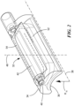
- Stator 30 includes a plurality of coil units 32, in this case, three such units 32a, 32b, and 32c. An individual one of the coil units 32 is depicted in FIG. 2 .
- Each unit 32 of the stator 30 includes a housing 34 having an arcuate inner surface 36 generally in the form of a partial surface of revolution around a unit axis 38. In the embodiments shown, each arcuate inner surface is a sector of a cylinder coaxial with an axis 38.
- the arcuate inner surface 36 has a radius R is substantially equal to the radius of the outer surface of pump housing 10. Stated another way, the arcuate inner surface 36 is a surface complimentary to a portion of the outer surface of the pump housing 10.
- the housing 34 of each unit 32 includes a tubular guide channel 40 extending parallel to the unit axis 38 on the exterior side of the housing, i.e., on the side opposite from arcuate surface 36.
- a ferromagnetic pole piece 42 is disposed within the housing 34 of each unit 32.
- the pole piece is a generally rectangular solid having a central axis 48 transverse to the unit axis.
- the pole piece 42 also includes a wide portion 50 adjacent the inner surface 36. This portion desirably has an interior surface conforming to the interior surface 36 of the housing.
- the wide portion 50 of the pole piece may define a portion of the interior surface.
- a coil 52 includes a plurality of turns 54 of an electrical conductor such as a wire extending around pole piece 42 and axis 48, only one such turn being shown in broken lines in FIG. 2 for clarity of illustration.
- External conductive leads (not shown) are electrically connected to coil 52. These external leads extend from the housing. The housing protects the coil from the surrounding environment.
- a set of elongated, flexible guides 56a-56c are fastened to the pump housing 10 ( FIG. 3 ).
- Each guide has a fixed end 58 attached to the pump housing adjacent the inlet end 12 of the housing.
- the fixed ends 58 of the guides are fastened to the exterior surface of the pump housing at equally spaced intervals around the axis of the pump housing.
- Each guide extends through the guide channel 40 ( FIG. 2 ) of one stator unit 32.
- guide 56a extends through the channel of stator unit 32a ( FIG.3 )
- guide 56b extends through the channel of stator unit 32b
- guide 56c extends through the channel of stator unit 32c.
- the external surface of pump housing 10 may have additional guide elements such as small ribs projecting from its outer surface (not shown) and extending generally in the axial direction. These ribs may be arranged to engage the housings of stator units 32a-32b and to guide each such stator unit into the operative position 30' of the stator shown in FIGS. 1-4 . Also, the exterior of the pump housing 10 may be provided with one or more stops for arresting motion of each stator unit along the axial direction of the pump housing when the stator unit reaches the operative position as discussed below.
- a flexible, hollow inlet tube 60 ( FIG. 3 ) is connected to the inlet end 12 of pump housing 10. The tube 60 has a smooth inlet end 62 with opening 64.
- the pump can be implanted by a delivery device 70.
- the delivery device 70 includes a central shaft 72 ( FIG.1 ) defining a major longitudinal axis extending in a distal direction denoted by arrow D in FIG. 1 and an opposite proximal direction denoted by arrow P. Only the distal end of the shaft is visible in FIG. 1 .
- a fitting 74 at the distal end of shaft 72 defines a conical guide surface 76 flaring outwardly in the distal direction. This guide surface is concentric with central shaft 72.
- Fitting 74 further defines a seat 78 adapted to engage the outlet end 14 of housing 10 and thus hold the housing on the central shaft with the axis 16 of the housing coaxial with the distal end of shaft 72.
- the seat 78 desirably is adapted to release from the housing upon command.
- the housing 10 may have features such as one or more holes or projections (not shown) on its interior or exterior surfaces, and seat 78 may have one or more movable elements such as pins or hooks adapted to engage these features of the housing 10. These elements desirably can be selectively actuated by an operator from the proximal end of the shaft.
- the shaft 72 may include one or more flexible wires (not shown) extending within it so that movement can be transmitted from the proximal end of the shaft to the hook or pin to release housing 10 from its engagement with seat 78. Any other device capable of actuating an element at a distal end of a shaft can be used.
- housing 10 may be held to seat 78 by one or more sutures that extend through the central shaft 72 or through other elements of the delivery device 70, and the housing may be released from the shaft by pulling on an end of the suture exposed at the proximal end of the shaft.
- Shaft 72 and fitting 74 are omitted in FIGS. 3 and 4 for clarity of illustration.
- the units 32a, 32b, and 32c of stator 30 are arranged in a row, i.e. successively, and extend along central shaft 72 and a delivery axis substantially coaxial with the axis of the housing 10.
- Each unit 32 is offset from the next adjacent unit in the proximal direction indicated by arrow P or in the opposite, distal direction D along the delivery axis.
- only one unit 32 is present at any point along the proximal or distal extent of the central shaft 72 and along the delivery axis.
- the entire stator 30, in its delivery configuration has a diameter in a plane transverse to the delivery axis approximately equal to the width of a single stator unit 32 ( FIG.2 ).
- the term "diameter” refers to the diameter of the smallest circle in a plane perpendicular to the axis of the structure through which the structure can pass.
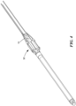
- the delivery device 70 is also configured to transition the stator units 32 so as to bring the stator 30 from the delivery configuration to the operative configuration illustrated at 30' in FIG. 1 and illustrated in FIG. 4 .
- One structure that is capable of performing this function is schematically indicated in FIG. 3 .
- This structure includes a plurality of hollow pusher shafts 80 disposed within an outer sheath 82. Each such pusher shaft 80 surrounds one of the guides 56a-56c.
- the central shaft 72 ( FIG.1 ) is also disposed within outer shaft 82, but is omitted in FIG. 3 for clarity of illustration. A proximal end of each pusher shaft 80 is accessible at the proximal end of the outer shaft 82. Only the distal end of shaft 82 is shown in FIG. 3 .
- each pusher shaft 80 can be slid in the distal direction D along the associated guide so as to force one of the stator units 32 from its delivery position to its position in the operative configuration.
- shaft 80a can be slid along guide 56a to move stator unit 32a distally.
- stator unit 32 moves distally, it slides over the flaring conical surface 76 of fitting 74 and slides over the outer surface of pump housing 10 to its operative position indicated at 32a' in FIG. 1 .
- the other units 32b and 32c can be positioned in their respective final positions by moving the other shafts 80b and 80c in a similar manner.
- This movement device is merely exemplary.
- Other mechanisms capable of moving elements at or near the distal end of a delivery device 70 while the distal end is disposed within the body of a subject may be used.
- suture loops may be used to pull, rather than push, the stator units.
- the pump When the pump is in its delivery condition, with the stator in the delivery configuration, the pump as a whole has a relatively small diameter. Stated another way, the entire pump can pass through a circle having a diameter equal to or slightly larger than the diameter of pump housing 10 alone.
- the diameter of the pump is larger than the diameter of the pump housing.
- the pump is implanted into a body of a living subject. While the pump is in its delivery condition, with the pump housing attached to fitting 74 of the central shaft and with the stator in its delivery configuration, the delivery device 70 and pump are advanced into the body of a subject.
- the pump is to be implanted in the vascular system and thus is advanced through the vasculature of the subject.
- the pump may be inserted into a peripheral artery of the subject and advanced towards a target location.
- the target location is in the ascending or descending aorta.
- the pump may be introduced through an opening in the femoral artery through a small incision in the skin.
- the pump may be introduced into an artery through an aortotomy in an artery remote from the aorta and again advanced through the arteries toward the aorta until the pump reaches a target location.
- the inlet tube 60 FIGS. 3-4
- the small delivery diameter facilitates advancement of the pump into the subject's body.
- the pump may be placed through a surgically created opening in the patient's heart and advanced through the heart or through another organ to the target location.
- the delivery device 70 is actuated to bring the stator to its operative configuration and thus bring the pump to the operative condition.
- outer sheath 82 may be retracted to expose the stator units, and pusher tubes 80 may be advanced distally to move the stator units 32 to the operative position 30' shown in FIG. 4 .
- Fitting 74 ( FIG.1 ) on the inner shaft 72 is disengaged from the housing 10 of the pump, and the delivery device 70 is removed.
- the leads (not shown) associated with the stator units may be left in place, extending through the vasculature to the location where the delivery device 70 was inserted into the vasculature, and may be connected to a conventional controller (not shown) adapted to provide power to the stator units.
- the guides 56a-56c may remain in place or may be removed.
- the pump optionally may include a device such as an expandable anchor (not shown) attached to the pump housing 10 or to one or more of the stator units.
- a device such as an expandable anchor (not shown) attached to the pump housing 10 or to one or more of the stator units.
- an expandable anchor may hold the pump in location as, for example, at a target location in the aorta.
- the expandable anchor is in a collapsed condition when the pump is advanced into the vasculature.
- a pump according to a further embodiment of the invention has a stator with a delivery configuration shown in FIG. 5 and an operative configuration shown in FIG. 6 .
- the stator 130 includes plural stator units 152 similar to the stator units discussed above.
- the stator units are not arranged in a row, but rather are stacked on one another.
- the stator units are connected to one another by one or more elements 101 formed from deformable material. Each such element may be a web or mesh of a shape memory alloy as, for example, a nitinol alloy.
- Each such element 101 is arranged to deform spontaneously from its shape as shown in the delivery configuration to an operative shape 101' ( FIG.6 ).
- the shape memory alloy may be arranged to deform upon exposure to body temperature.
- the shape memory alloy may be arranged to deform to the operative position under its own elasticity and may be restrained in the delivery configuration by the delivery device 70.
- the stator in its operative condition 130' forms a generally tubular unit with an interior space between the stator units. In the operative configuration, the stator may be slid onto the outside of the pump housing, so that the pump housing is received within this generally tubular unit.
- a stator in its operative condition includes a generally tubular housing having a wall 235 defining an interior bore 233.
- Coils 254, one of which is schematically depicted in FIG. 7 are embedded within the wall 235.
- the stator is compressed by folding wall 235 generally along lines parallel to the axis of the tubular housing so as to bring one portion 235a of the wall close to another portion 235b, within the space normally occupied by bore 233, and thus compress the stator to a smaller diameter.
- the stator according to this embodiment may omit the ferromagnetic cores usually present in the stator coils.
- the stator 230 may be brought to the operative configuration 230' by the resilience of the wall.
- the stator may be constrained by a sheath incorporated in the delivery device 70 and may revert to the operative configuration when the stator is ejected from the sheath.
- a mechanical expansion device or an inflatable device such as a balloon may be disposed within the stator. The balloon is inflated to bring the stator to its operative condition.
- the housing may incorporate ferromagnetic elements to perform a similar function.
- the rotor may be provided with hydrodynamic thrust bearings and the housing may be provided with complementary surfaces so that hydrodynamic action maintains the rotor in position relative to the housing.
- the housing and rotor may incorporate mechanical bearings to or to control the axial position of the rotor relative to the housing, to maintain the rotor coaxial with the stator, or both.
Landscapes
- Health & Medical Sciences (AREA)
- Heart & Thoracic Surgery (AREA)
- Engineering & Computer Science (AREA)
- Biomedical Technology (AREA)
- Life Sciences & Earth Sciences (AREA)
- Veterinary Medicine (AREA)
- Mechanical Engineering (AREA)
- Anesthesiology (AREA)
- Public Health (AREA)
- Hematology (AREA)
- Cardiology (AREA)
- Animal Behavior & Ethology (AREA)
- General Health & Medical Sciences (AREA)
- Vascular Medicine (AREA)
- Physics & Mathematics (AREA)
- Fluid Mechanics (AREA)
- Transplantation (AREA)
- External Artificial Organs (AREA)
- Structures Of Non-Positive Displacement Pumps (AREA)
Claims (8)
- Blutpumpe, umfassend:ein Gehäuse (10) mit einem Innen- und einem Außenbereich;einen Pumpenrotor (18), der so konfiguriert ist, dass er im Inneren des Gehäuses aufgenommen wird, wobei der Pumpenrotor einen Magneten einschließt; undeinen Stator mit einer Abgabekonfiguration (30) und einer Betriebskonfiguration (30'), wobei der Stator in der Abgabekonfiguration einen Abgabedurchmesser aufweist und der Stator in der Betriebskonfiguration so konfiguriert ist, dass er um die Außenseite des Gehäuses angeordnet ist und eine montierte Pumpe mit einem Durchmesser bildet, der größer ist als der Abgabedurchmesser, wobei das Gehäuse eine Gehäuseachse (16) und axiale Richtungen entlang der Gehäuseachse definiert, und der Stator eine Vielzahl von Einheiten (32) einschließt und jede Einheit eine Spule (52) mit einer Spulenachse (48) und einen elektrischen Leiter aufweist, der in einer oder mehreren Windungen (54) angeordnet ist, die die Spulenachse umgeben, wobei der Stator in der Betriebskonfiguration die Einheiten um die Gehäuseachse herum angeordnet aufweist, wobei die Spulenachsen der Einheiten quer zur Gehäuseachse verlaufen, und wobei in der Abgabekonfiguration:der Stator eine Abgabeachse aufweist;die Spulenachsen quer zur Abgabeachse verlaufen; undmindestens eine der Einheiten in einer Richtung entlang der Abgabeachse gegenüber einer anderen Einheit versetzt ist.
- Blutpumpe nach Anspruch 1, wobei in der Abgabekonfiguration die Einheiten des Stators in einer Reihe entlang der Abgabeachse angeordnet sind, wobei jede der Einheiten in einer Richtung entlang der Abgabeachse von einer benachbarten Einheit versetzt ist.
- Blutpumpe nach Anspruch 1, wobei das Gehäuse eine Außenoberfläche mit einer oder mehreren bogenförmigen Oberflächen (36) aufweist, die koaxial zur Gehäuseachse verlaufen, und wobei jede der Einheiten eine Innenoberfläche in Form einer teilweisen Rotationsfläche um eine Einheitenachse (38) aufweist, die quer zur Spulenachse dieser Einheit verläuft, wobei die Innenoberflächen jeder Einheit den bogenförmigen Oberflächen des Gehäuses gegenüberliegen, wenn sich der Stator in der Betriebskonfiguration befindet.
- Blutpumpe nach einem der Ansprüche 1 bis 3, wobei der Stator ein flexibles Element mit einer oder mehreren Spulen umfasst, wobei sich das flexible Element um das Gehäuse herum erstreckt, wenn sich der Stator im Betriebszustand befindet.
- Blutpumpe nach Anspruch 4, wobei das flexible Element, wenn sich der Stator in der Betriebskonfiguration befindet, ein Rohr (60) bildet und das Pumpengehäuse innerhalb des Rohrs angeordnet ist, und wobei das flexible Element gefaltet ist, wenn sich der Stator in der Abgabekonfiguration befindet.
- Blutpumpe nach einem der Ansprüche 1 bis 5, wobei der Stator im Abgabezustand so ausgebildet ist, dass er durch eine Abgabevorrichtung in den Betriebszustand überführt werden kann.
- Blutpumpe nach Anspruch 6, wobei die Abgabevorrichtung so konfiguriert ist, dass sie die Einheiten entlang der Hauptlängsachse in Richtung des Pumpengehäuses vorschiebt, um die Pumpe vom Abgabezustand in den Betriebszustand zu bringen.
- Blutpumpe nach Anspruch 6, wobei die Blutpumpe so konfiguriert ist, dass sie lösbar an der Abgabevorrichtung befestigt werden kann.
Applications Claiming Priority (2)
| Application Number | Priority Date | Filing Date | Title |
|---|---|---|---|
| US201662411781P | 2016-10-24 | 2016-10-24 | |
| PCT/US2017/057969 WO2018081040A1 (en) | 2016-10-24 | 2017-10-24 | Blood pump with in-situ attaching motor stators |
Publications (2)
| Publication Number | Publication Date |
|---|---|
| EP3528865A1 EP3528865A1 (de) | 2019-08-28 |
| EP3528865B1 true EP3528865B1 (de) | 2024-08-07 |
Family
ID=60263106
Family Applications (1)
| Application Number | Title | Priority Date | Filing Date |
|---|---|---|---|
| EP17794582.1A Active EP3528865B1 (de) | 2016-10-24 | 2017-10-24 | Blutpumpe mit in-situ befestigung von motorstatoren |
Country Status (4)
| Country | Link |
|---|---|
| US (2) | US10556048B2 (de) |
| EP (1) | EP3528865B1 (de) |
| CN (1) | CN109862924B (de) |
| WO (1) | WO2018081040A1 (de) |
Families Citing this family (28)
| Publication number | Priority date | Publication date | Assignee | Title |
|---|---|---|---|---|
| DE102018201030B4 (de) | 2018-01-24 | 2025-10-16 | Kardion Gmbh | Magnetkuppelelement mit magnetischer Lagerungsfunktion |
| US11690997B2 (en) | 2018-04-06 | 2023-07-04 | Puzzle Medical Devices Inc. | Mammalian body conduit intralumenal device and lumen wall anchor assembly, components thereof and methods of implantation and explanation thereof |
| DE102018207594A1 (de) | 2018-05-16 | 2019-11-21 | Kardion Gmbh | Rotor, Magnetkupplungsvorrichtung, Elektromotor für ein Herzunterstützungssystem, Pumpeneinheit für ein Herzunterstützungssystem sowie Verfahren zum Herstellen eines Rotors |
| DE102018207575A1 (de) | 2018-05-16 | 2019-11-21 | Kardion Gmbh | Magnetische Stirndreh-Kupplung zur Übertragung von Drehmomenten |
| DE102018207611A1 (de) | 2018-05-16 | 2019-11-21 | Kardion Gmbh | Rotorlagerungssystem |
| DE102018208555A1 (de) | 2018-05-30 | 2019-12-05 | Kardion Gmbh | Vorrichtung zum Verankern eines Herzunterstützungssystems in einem Blutgefäß, Verfahren zum Betreiben und Herstellverfahren zum Herstellen einer Vorrichtung und Herzunterstützungssystem |
| DE102018208550A1 (de) | 2018-05-30 | 2019-12-05 | Kardion Gmbh | Leitungsvorrichtung zum Leiten eines Blutstroms für ein Herzunterstützungssystem, Herzunterstützungssystem und Verfahren zum Herstellen einer Leitungsvorrichtung |
| DE102018208564A1 (de) | 2018-05-30 | 2019-12-05 | Kardion Gmbh | Steuerbare Einführungshülse |
| DE102018208541A1 (de) | 2018-05-30 | 2019-12-05 | Kardion Gmbh | Axialpumpe für ein Herzunterstützungssystem und Verfahren zum Herstellen einer Axialpumpe für ein Herzunterstützungssystem |
| DE102018208537A1 (de) | 2018-05-30 | 2019-12-05 | Kardion Gmbh | Vorrichtung zum Anbinden eines Herzunterstützungssystems an eine Einführeinrichtung und Verfahren zum Herstellen einer Vorrichtung zum Anbinden eines Herzunterstützungssystems an eine Einführeinrichtung |
| DE102018208538A1 (de) | 2018-05-30 | 2019-12-05 | Kardion Gmbh | Intravasale Blutpumpe und Verfahren zur Herstellung von elektrischen Leiterbahnen |
| DE102018208549A1 (de) | 2018-05-30 | 2019-12-05 | Kardion Gmbh | Elektronikmodul für ein Herzunterstützungssystem und Verfahren zum Herstellen eines Elektronikmoduls für ein Herzunterstützungssystem |
| DE102018208539A1 (de) | 2018-05-30 | 2019-12-05 | Kardion Gmbh | Motorgehäusemodul zum Abdichten eines Motorraums eines Motors eines Herzunterstützungssystems und Herzunterstützungssystem und Verfahren zum Montieren eines Herzunterstützungssystems |
| DE102018210058A1 (de) | 2018-06-21 | 2019-12-24 | Kardion Gmbh | Statorschaufelvorrichtung zur Strömungsführung eines aus einer Austrittsöffnung eines Herzunterstützungssystems ausströmenden Fluids, Herzunterstützungssystem mit Statorschaufelvorrichtung, Verfahren zum Betreiben einer Statorschaufelvorrichtung und Herstellverfahren |
| DE102018210076A1 (de) | 2018-06-21 | 2019-12-24 | Kardion Gmbh | Verfahren und Vorrichtung zum Erkennen eines Verschleißzustands eines Herzunterstützungssystems, Verfahren und Vorrichtung zum Betreiben eines Herzunterstützungssystems und Herzunterstützungssystem |
| DE102018211297A1 (de) | 2018-07-09 | 2020-01-09 | Kardion Gmbh | Herzunterstützungssystem und Verfahren zur Überwachung der Integrität einer Haltestruktur eines Herzunterstützungssystems |
| DE102018211327A1 (de) | 2018-07-10 | 2020-01-16 | Kardion Gmbh | Laufrad für ein implantierbares, vaskuläres Unterstützungssystem |
| DE102018211328A1 (de) | 2018-07-10 | 2020-01-16 | Kardion Gmbh | Laufradgehäuse für ein implantierbares, vaskuläres Unterstützungssystem |
| DE102018212153A1 (de) | 2018-07-20 | 2020-01-23 | Kardion Gmbh | Zulaufleitung für eine Pumpeneinheit eines Herzunterstützungssystems, Herzunterstützungssystem und Verfahren zum Herstellen einer Zulaufleitung für eine Pumpeneinheit eines Herzunterstützungssystems |
| AU2019320533B2 (en) | 2018-08-07 | 2024-11-21 | Kardion Gmbh | Bearing device for a cardiac support system, and method for flushing an intermediate space in a bearing device for a cardiac support system |
| CN119113374A (zh) * | 2019-03-26 | 2024-12-13 | 益智医疗器械股份有限公司 | 模块化哺乳动物身体可植入流体流动影响装置和相关方法 |
| US12383723B2 (en) | 2019-10-05 | 2025-08-12 | Puzzle Medical Devices Inc. | Mammalian body implantable fluid flow influencing device |
| DE102020102474A1 (de) | 2020-01-31 | 2021-08-05 | Kardion Gmbh | Pumpe zum Fördern eines Fluids und Verfahren zum Herstellen einer Pumpe |
| CA3192451A1 (en) | 2020-09-14 | 2022-03-17 | Johannes Bette | Cardiovascular support pump having an impeller with a variable flow area |
| JP2023550938A (ja) | 2020-11-20 | 2023-12-06 | カルディオン ゲーエムベーハー | ガイドワイヤ補助具付き機械的循環支持システム |
| CN115445076B (zh) * | 2022-03-25 | 2023-12-01 | 心擎医疗(苏州)股份有限公司 | 导管泵及折叠导管泵的泵头的方法 |
| IL320366A (en) | 2022-11-01 | 2025-06-01 | Puzzle Medical Devices Inc | Missile medical devices and methods related thereto |
| CN116637290A (zh) * | 2023-05-23 | 2023-08-25 | 安徽通灵仿生科技有限公司 | 并联式血泵 |
Family Cites Families (11)
| Publication number | Priority date | Publication date | Assignee | Title |
|---|---|---|---|---|
| ES2227718T3 (es) * | 1996-10-04 | 2005-04-01 | United States Surgical Corporation | Sistema de apoyo circulatorio. |
| US20090069854A1 (en) * | 2005-04-21 | 2009-03-12 | Eqlibra Medical Ltd. | Implantable electric device |
| US20090112312A1 (en) | 2007-02-26 | 2009-04-30 | Larose Jeffrey A | Intravascular ventricular assist device |
| EP2432515B1 (de) * | 2009-05-18 | 2014-05-07 | Cardiobridge GmbH | Katheterpumpe |
| EP2448613B1 (de) * | 2009-07-01 | 2019-11-06 | The Penn State Research Foundation | Blutpumpe mit expandierbarer kanüle |
| US8690749B1 (en) | 2009-11-02 | 2014-04-08 | Anthony Nunez | Wireless compressible heart pump |
| AU2012207146B2 (en) * | 2011-01-21 | 2016-10-06 | Heartware, Inc. | Flow estimation in a blood pump |
| CN104185481B (zh) * | 2012-02-07 | 2017-02-22 | 赫莱达雅公司 | 血液动力学辅助设备 |
| WO2015023850A1 (en) | 2013-08-14 | 2015-02-19 | Heartware, Inc. | Impeller for axial flow pump |
| EP2860849B1 (de) * | 2013-10-11 | 2016-09-14 | ECP Entwicklungsgesellschaft mbH | Komprimierbarer Motor, Implantieranordnung sowie Verfahren zum Positionieren des Motors |
| DE102014211216A1 (de) | 2014-06-12 | 2015-12-17 | Universität Duisburg-Essen | Pumpe zur Implantierung in ein Gefäß |
-
2017
- 2017-10-24 EP EP17794582.1A patent/EP3528865B1/de active Active
- 2017-10-24 US US15/791,573 patent/US10556048B2/en active Active
- 2017-10-24 CN CN201780065614.XA patent/CN109862924B/zh active Active
- 2017-10-24 WO PCT/US2017/057969 patent/WO2018081040A1/en not_active Ceased
-
2020
- 2020-01-03 US US16/733,386 patent/US11305103B2/en active Active
Also Published As
| Publication number | Publication date |
|---|---|
| CN109862924A (zh) | 2019-06-07 |
| US20200139030A1 (en) | 2020-05-07 |
| US10556048B2 (en) | 2020-02-11 |
| EP3528865A1 (de) | 2019-08-28 |
| WO2018081040A9 (en) | 2018-08-09 |
| US20180110909A1 (en) | 2018-04-26 |
| CN109862924B (zh) | 2021-09-21 |
| WO2018081040A1 (en) | 2018-05-03 |
| US11305103B2 (en) | 2022-04-19 |
Similar Documents
| Publication | Publication Date | Title |
|---|---|---|
| US11305103B2 (en) | Blood pump with in-situ attaching motor stators | |
| US12395033B2 (en) | Compressible motor, implantation arrangement, and method for positioning the motor | |
| JP2023505795A (ja) | 血管内血液ポンプの支持構造 | |
| JP2017501663A5 (de) | ||
| US20090069854A1 (en) | Implantable electric device | |
| CA2322012A1 (en) | Self-deploying axial-flow pump introduced intravascularly for temporary cardiac support | |
| HK40045468A (en) | Compressible motor, implanting assembly and method for positioning the motor | |
| HK1222948B (zh) | 可压缩电机、植入装置及定位电机的方法 |
Legal Events
| Date | Code | Title | Description |
|---|---|---|---|
| STAA | Information on the status of an ep patent application or granted ep patent |
Free format text: STATUS: UNKNOWN |
|
| STAA | Information on the status of an ep patent application or granted ep patent |
Free format text: STATUS: THE INTERNATIONAL PUBLICATION HAS BEEN MADE |
|
| PUAI | Public reference made under article 153(3) epc to a published international application that has entered the european phase |
Free format text: ORIGINAL CODE: 0009012 |
|
| STAA | Information on the status of an ep patent application or granted ep patent |
Free format text: STATUS: REQUEST FOR EXAMINATION WAS MADE |
|
| 17P | Request for examination filed |
Effective date: 20190520 |
|
| AK | Designated contracting states |
Kind code of ref document: A1 Designated state(s): AL AT BE BG CH CY CZ DE DK EE ES FI FR GB GR HR HU IE IS IT LI LT LU LV MC MK MT NL NO PL PT RO RS SE SI SK SM TR |
|
| AX | Request for extension of the european patent |
Extension state: BA ME |
|
| DAV | Request for validation of the european patent (deleted) | ||
| DAX | Request for extension of the european patent (deleted) | ||
| STAA | Information on the status of an ep patent application or granted ep patent |
Free format text: STATUS: EXAMINATION IS IN PROGRESS |
|
| 17Q | First examination report despatched |
Effective date: 20230405 |
|
| REG | Reference to a national code |
Ref country code: DE Ref legal event code: R079 Free format text: PREVIOUS MAIN CLASS: A61M0001100000 Ipc: A61M0060135000 Ref document number: 602017083916 Country of ref document: DE |
|
| GRAP | Despatch of communication of intention to grant a patent |
Free format text: ORIGINAL CODE: EPIDOSNIGR1 |
|
| STAA | Information on the status of an ep patent application or granted ep patent |
Free format text: STATUS: GRANT OF PATENT IS INTENDED |
|
| INTG | Intention to grant announced |
Effective date: 20240418 |
|
| RIC1 | Information provided on ipc code assigned before grant |
Ipc: A61M 60/824 20210101ALI20240405BHEP Ipc: A61M 60/422 20210101ALI20240405BHEP Ipc: A61M 60/237 20210101ALI20240405BHEP Ipc: A61M 60/135 20210101AFI20240405BHEP |
|
| GRAS | Grant fee paid |
Free format text: ORIGINAL CODE: EPIDOSNIGR3 |
|
| GRAA | (expected) grant |
Free format text: ORIGINAL CODE: 0009210 |
|
| STAA | Information on the status of an ep patent application or granted ep patent |
Free format text: STATUS: THE PATENT HAS BEEN GRANTED |
|
| AK | Designated contracting states |
Kind code of ref document: B1 Designated state(s): AL AT BE BG CH CY CZ DE DK EE ES FI FR GB GR HR HU IE IS IT LI LT LU LV MC MK MT NL NO PL PT RO RS SE SI SK SM TR |
|
| REG | Reference to a national code |
Ref country code: GB Ref legal event code: FG4D |
|
| REG | Reference to a national code |
Ref country code: CH Ref legal event code: EP |
|
| REG | Reference to a national code |
Ref country code: IE Ref legal event code: FG4D |
|
| REG | Reference to a national code |
Ref country code: DE Ref legal event code: R096 Ref document number: 602017083916 Country of ref document: DE |
|
| REG | Reference to a national code |
Ref country code: LT Ref legal event code: MG9D |
|
| REG | Reference to a national code |
Ref country code: NL Ref legal event code: MP Effective date: 20240807 |
|
| PG25 | Lapsed in a contracting state [announced via postgrant information from national office to epo] |
Ref country code: NO Free format text: LAPSE BECAUSE OF FAILURE TO SUBMIT A TRANSLATION OF THE DESCRIPTION OR TO PAY THE FEE WITHIN THE PRESCRIBED TIME-LIMIT Effective date: 20241107 |
|
| REG | Reference to a national code |
Ref country code: AT Ref legal event code: MK05 Ref document number: 1710283 Country of ref document: AT Kind code of ref document: T Effective date: 20240807 |
|
| PG25 | Lapsed in a contracting state [announced via postgrant information from national office to epo] |
Ref country code: FI Free format text: LAPSE BECAUSE OF FAILURE TO SUBMIT A TRANSLATION OF THE DESCRIPTION OR TO PAY THE FEE WITHIN THE PRESCRIBED TIME-LIMIT Effective date: 20240807 Ref country code: NL Free format text: LAPSE BECAUSE OF FAILURE TO SUBMIT A TRANSLATION OF THE DESCRIPTION OR TO PAY THE FEE WITHIN THE PRESCRIBED TIME-LIMIT Effective date: 20240807 Ref country code: PT Free format text: LAPSE BECAUSE OF FAILURE TO SUBMIT A TRANSLATION OF THE DESCRIPTION OR TO PAY THE FEE WITHIN THE PRESCRIBED TIME-LIMIT Effective date: 20241209 Ref country code: PL Free format text: LAPSE BECAUSE OF FAILURE TO SUBMIT A TRANSLATION OF THE DESCRIPTION OR TO PAY THE FEE WITHIN THE PRESCRIBED TIME-LIMIT Effective date: 20240807 Ref country code: GR Free format text: LAPSE BECAUSE OF FAILURE TO SUBMIT A TRANSLATION OF THE DESCRIPTION OR TO PAY THE FEE WITHIN THE PRESCRIBED TIME-LIMIT Effective date: 20241108 |
|
| PG25 | Lapsed in a contracting state [announced via postgrant information from national office to epo] |
Ref country code: BG Free format text: LAPSE BECAUSE OF FAILURE TO SUBMIT A TRANSLATION OF THE DESCRIPTION OR TO PAY THE FEE WITHIN THE PRESCRIBED TIME-LIMIT Effective date: 20240807 |
|
| PG25 | Lapsed in a contracting state [announced via postgrant information from national office to epo] |
Ref country code: LV Free format text: LAPSE BECAUSE OF FAILURE TO SUBMIT A TRANSLATION OF THE DESCRIPTION OR TO PAY THE FEE WITHIN THE PRESCRIBED TIME-LIMIT Effective date: 20240807 |
|
| PG25 | Lapsed in a contracting state [announced via postgrant information from national office to epo] |
Ref country code: AT Free format text: LAPSE BECAUSE OF FAILURE TO SUBMIT A TRANSLATION OF THE DESCRIPTION OR TO PAY THE FEE WITHIN THE PRESCRIBED TIME-LIMIT Effective date: 20240807 Ref country code: IS Free format text: LAPSE BECAUSE OF FAILURE TO SUBMIT A TRANSLATION OF THE DESCRIPTION OR TO PAY THE FEE WITHIN THE PRESCRIBED TIME-LIMIT Effective date: 20241207 |
|
| PG25 | Lapsed in a contracting state [announced via postgrant information from national office to epo] |
Ref country code: HR Free format text: LAPSE BECAUSE OF FAILURE TO SUBMIT A TRANSLATION OF THE DESCRIPTION OR TO PAY THE FEE WITHIN THE PRESCRIBED TIME-LIMIT Effective date: 20240807 |
|
| PG25 | Lapsed in a contracting state [announced via postgrant information from national office to epo] |
Ref country code: ES Free format text: LAPSE BECAUSE OF FAILURE TO SUBMIT A TRANSLATION OF THE DESCRIPTION OR TO PAY THE FEE WITHIN THE PRESCRIBED TIME-LIMIT Effective date: 20240807 Ref country code: RS Free format text: LAPSE BECAUSE OF FAILURE TO SUBMIT A TRANSLATION OF THE DESCRIPTION OR TO PAY THE FEE WITHIN THE PRESCRIBED TIME-LIMIT Effective date: 20241107 |
|
| PG25 | Lapsed in a contracting state [announced via postgrant information from national office to epo] |
Ref country code: RS Free format text: LAPSE BECAUSE OF FAILURE TO SUBMIT A TRANSLATION OF THE DESCRIPTION OR TO PAY THE FEE WITHIN THE PRESCRIBED TIME-LIMIT Effective date: 20241107 Ref country code: PT Free format text: LAPSE BECAUSE OF FAILURE TO SUBMIT A TRANSLATION OF THE DESCRIPTION OR TO PAY THE FEE WITHIN THE PRESCRIBED TIME-LIMIT Effective date: 20241209 Ref country code: PL Free format text: LAPSE BECAUSE OF FAILURE TO SUBMIT A TRANSLATION OF THE DESCRIPTION OR TO PAY THE FEE WITHIN THE PRESCRIBED TIME-LIMIT Effective date: 20240807 Ref country code: NO Free format text: LAPSE BECAUSE OF FAILURE TO SUBMIT A TRANSLATION OF THE DESCRIPTION OR TO PAY THE FEE WITHIN THE PRESCRIBED TIME-LIMIT Effective date: 20241107 Ref country code: NL Free format text: LAPSE BECAUSE OF FAILURE TO SUBMIT A TRANSLATION OF THE DESCRIPTION OR TO PAY THE FEE WITHIN THE PRESCRIBED TIME-LIMIT Effective date: 20240807 Ref country code: LV Free format text: LAPSE BECAUSE OF FAILURE TO SUBMIT A TRANSLATION OF THE DESCRIPTION OR TO PAY THE FEE WITHIN THE PRESCRIBED TIME-LIMIT Effective date: 20240807 Ref country code: IS Free format text: LAPSE BECAUSE OF FAILURE TO SUBMIT A TRANSLATION OF THE DESCRIPTION OR TO PAY THE FEE WITHIN THE PRESCRIBED TIME-LIMIT Effective date: 20241207 Ref country code: HR Free format text: LAPSE BECAUSE OF FAILURE TO SUBMIT A TRANSLATION OF THE DESCRIPTION OR TO PAY THE FEE WITHIN THE PRESCRIBED TIME-LIMIT Effective date: 20240807 Ref country code: GR Free format text: LAPSE BECAUSE OF FAILURE TO SUBMIT A TRANSLATION OF THE DESCRIPTION OR TO PAY THE FEE WITHIN THE PRESCRIBED TIME-LIMIT Effective date: 20241108 Ref country code: FI Free format text: LAPSE BECAUSE OF FAILURE TO SUBMIT A TRANSLATION OF THE DESCRIPTION OR TO PAY THE FEE WITHIN THE PRESCRIBED TIME-LIMIT Effective date: 20240807 Ref country code: ES Free format text: LAPSE BECAUSE OF FAILURE TO SUBMIT A TRANSLATION OF THE DESCRIPTION OR TO PAY THE FEE WITHIN THE PRESCRIBED TIME-LIMIT Effective date: 20240807 Ref country code: BG Free format text: LAPSE BECAUSE OF FAILURE TO SUBMIT A TRANSLATION OF THE DESCRIPTION OR TO PAY THE FEE WITHIN THE PRESCRIBED TIME-LIMIT Effective date: 20240807 Ref country code: AT Free format text: LAPSE BECAUSE OF FAILURE TO SUBMIT A TRANSLATION OF THE DESCRIPTION OR TO PAY THE FEE WITHIN THE PRESCRIBED TIME-LIMIT Effective date: 20240807 |
|
| PG25 | Lapsed in a contracting state [announced via postgrant information from national office to epo] |
Ref country code: SM Free format text: LAPSE BECAUSE OF FAILURE TO SUBMIT A TRANSLATION OF THE DESCRIPTION OR TO PAY THE FEE WITHIN THE PRESCRIBED TIME-LIMIT Effective date: 20240807 Ref country code: RO Free format text: LAPSE BECAUSE OF FAILURE TO SUBMIT A TRANSLATION OF THE DESCRIPTION OR TO PAY THE FEE WITHIN THE PRESCRIBED TIME-LIMIT Effective date: 20240807 Ref country code: DK Free format text: LAPSE BECAUSE OF FAILURE TO SUBMIT A TRANSLATION OF THE DESCRIPTION OR TO PAY THE FEE WITHIN THE PRESCRIBED TIME-LIMIT Effective date: 20240807 |
|
| PG25 | Lapsed in a contracting state [announced via postgrant information from national office to epo] |
Ref country code: EE Free format text: LAPSE BECAUSE OF FAILURE TO SUBMIT A TRANSLATION OF THE DESCRIPTION OR TO PAY THE FEE WITHIN THE PRESCRIBED TIME-LIMIT Effective date: 20240807 |
|
| PG25 | Lapsed in a contracting state [announced via postgrant information from national office to epo] |
Ref country code: CZ Free format text: LAPSE BECAUSE OF FAILURE TO SUBMIT A TRANSLATION OF THE DESCRIPTION OR TO PAY THE FEE WITHIN THE PRESCRIBED TIME-LIMIT Effective date: 20240807 |
|
| PG25 | Lapsed in a contracting state [announced via postgrant information from national office to epo] |
Ref country code: SK Free format text: LAPSE BECAUSE OF FAILURE TO SUBMIT A TRANSLATION OF THE DESCRIPTION OR TO PAY THE FEE WITHIN THE PRESCRIBED TIME-LIMIT Effective date: 20240807 |
|
| REG | Reference to a national code |
Ref country code: DE Ref legal event code: R097 Ref document number: 602017083916 Country of ref document: DE |
|
| REG | Reference to a national code |
Ref country code: CH Ref legal event code: PL |
|
| PLBE | No opposition filed within time limit |
Free format text: ORIGINAL CODE: 0009261 |
|
| STAA | Information on the status of an ep patent application or granted ep patent |
Free format text: STATUS: NO OPPOSITION FILED WITHIN TIME LIMIT |
|
| PG25 | Lapsed in a contracting state [announced via postgrant information from national office to epo] |
Ref country code: MC Free format text: LAPSE BECAUSE OF FAILURE TO SUBMIT A TRANSLATION OF THE DESCRIPTION OR TO PAY THE FEE WITHIN THE PRESCRIBED TIME-LIMIT Effective date: 20240807 |
|
| PG25 | Lapsed in a contracting state [announced via postgrant information from national office to epo] |
Ref country code: LU Free format text: LAPSE BECAUSE OF NON-PAYMENT OF DUE FEES Effective date: 20241024 Ref country code: BE Free format text: LAPSE BECAUSE OF NON-PAYMENT OF DUE FEES Effective date: 20241031 |
|
| 26N | No opposition filed |
Effective date: 20250508 |
|
| PG25 | Lapsed in a contracting state [announced via postgrant information from national office to epo] |
Ref country code: FR Free format text: LAPSE BECAUSE OF NON-PAYMENT OF DUE FEES Effective date: 20241031 |
|
| GBPC | Gb: european patent ceased through non-payment of renewal fee |
Effective date: 20241107 |
|
| PG25 | Lapsed in a contracting state [announced via postgrant information from national office to epo] |
Ref country code: CH Free format text: LAPSE BECAUSE OF NON-PAYMENT OF DUE FEES Effective date: 20241031 |
|
| REG | Reference to a national code |
Ref country code: BE Ref legal event code: MM Effective date: 20241031 |
|
| PG25 | Lapsed in a contracting state [announced via postgrant information from national office to epo] |
Ref country code: SE Free format text: LAPSE BECAUSE OF FAILURE TO SUBMIT A TRANSLATION OF THE DESCRIPTION OR TO PAY THE FEE WITHIN THE PRESCRIBED TIME-LIMIT Effective date: 20240807 |
|
| PG25 | Lapsed in a contracting state [announced via postgrant information from national office to epo] |
Ref country code: GB Free format text: LAPSE BECAUSE OF NON-PAYMENT OF DUE FEES Effective date: 20241107 |
|
| PG25 | Lapsed in a contracting state [announced via postgrant information from national office to epo] |
Ref country code: IE Free format text: LAPSE BECAUSE OF NON-PAYMENT OF DUE FEES Effective date: 20241024 |
|
| PGFP | Annual fee paid to national office [announced via postgrant information from national office to epo] |
Ref country code: DE Payment date: 20250923 Year of fee payment: 9 |
|
| PG25 | Lapsed in a contracting state [announced via postgrant information from national office to epo] |
Ref country code: IT Free format text: LAPSE BECAUSE OF FAILURE TO SUBMIT A TRANSLATION OF THE DESCRIPTION OR TO PAY THE FEE WITHIN THE PRESCRIBED TIME-LIMIT Effective date: 20240807 Ref country code: CY Free format text: LAPSE BECAUSE OF FAILURE TO SUBMIT A TRANSLATION OF THE DESCRIPTION OR TO PAY THE FEE WITHIN THE PRESCRIBED TIME-LIMIT; INVALID AB INITIO Effective date: 20171024 |
|
| PG25 | Lapsed in a contracting state [announced via postgrant information from national office to epo] |
Ref country code: HU Free format text: LAPSE BECAUSE OF FAILURE TO SUBMIT A TRANSLATION OF THE DESCRIPTION OR TO PAY THE FEE WITHIN THE PRESCRIBED TIME-LIMIT; INVALID AB INITIO Effective date: 20171024 |