EP3529006B1 - Procédé de commande et module de rinçage de trou de forage - Google Patents
Procédé de commande et module de rinçage de trou de forage Download PDFInfo
- Publication number
- EP3529006B1 EP3529006B1 EP17781134.6A EP17781134A EP3529006B1 EP 3529006 B1 EP3529006 B1 EP 3529006B1 EP 17781134 A EP17781134 A EP 17781134A EP 3529006 B1 EP3529006 B1 EP 3529006B1
- Authority
- EP
- European Patent Office
- Prior art keywords
- flushing module
- tool
- borehole
- detector
- drill
- Prior art date
- Legal status (The legal status is an assumption and is not a legal conclusion. Google has not performed a legal analysis and makes no representation as to the accuracy of the status listed.)
- Active
Links
Images


Classifications
-
- B—PERFORMING OPERATIONS; TRANSPORTING
- B25—HAND TOOLS; PORTABLE POWER-DRIVEN TOOLS; MANIPULATORS
- B25D—PERCUSSIVE TOOLS
- B25D17/00—Details of, or accessories for, portable power-driven percussive tools
- B25D17/26—Lubricating
-
- B—PERFORMING OPERATIONS; TRANSPORTING
- B25—HAND TOOLS; PORTABLE POWER-DRIVEN TOOLS; MANIPULATORS
- B25D—PERCUSSIVE TOOLS
- B25D17/00—Details of, or accessories for, portable power-driven percussive tools
- B25D17/20—Devices for cleaning or cooling tool or work
-
- B—PERFORMING OPERATIONS; TRANSPORTING
- B23—MACHINE TOOLS; METAL-WORKING NOT OTHERWISE PROVIDED FOR
- B23Q—DETAILS, COMPONENTS, OR ACCESSORIES FOR MACHINE TOOLS, e.g. ARRANGEMENTS FOR COPYING OR CONTROLLING; MACHINE TOOLS IN GENERAL CHARACTERISED BY THE CONSTRUCTION OF PARTICULAR DETAILS OR COMPONENTS; COMBINATIONS OR ASSOCIATIONS OF METAL-WORKING MACHINES, NOT DIRECTED TO A PARTICULAR RESULT
- B23Q11/00—Accessories fitted to machine tools for keeping tools or parts of the machine in good working condition or for cooling work; Safety devices specially combined with or arranged in, or specially adapted for use in connection with, machine tools
- B23Q11/0042—Devices for removing chips
- B23Q11/005—Devices for removing chips by blowing
-
- B—PERFORMING OPERATIONS; TRANSPORTING
- B23—MACHINE TOOLS; METAL-WORKING NOT OTHERWISE PROVIDED FOR
- B23Q—DETAILS, COMPONENTS, OR ACCESSORIES FOR MACHINE TOOLS, e.g. ARRANGEMENTS FOR COPYING OR CONTROLLING; MACHINE TOOLS IN GENERAL CHARACTERISED BY THE CONSTRUCTION OF PARTICULAR DETAILS OR COMPONENTS; COMBINATIONS OR ASSOCIATIONS OF METAL-WORKING MACHINES, NOT DIRECTED TO A PARTICULAR RESULT
- B23Q17/00—Arrangements for observing, indicating or measuring on machine tools
- B23Q17/20—Arrangements for observing, indicating or measuring on machine tools for indicating or measuring workpiece characteristics, e.g. contour, dimension, hardness
-
- B—PERFORMING OPERATIONS; TRANSPORTING
- B25—HAND TOOLS; PORTABLE POWER-DRIVEN TOOLS; MANIPULATORS
- B25D—PERCUSSIVE TOOLS
- B25D16/00—Portable percussive machines with superimposed rotation, the rotational movement of the output shaft of a motor being modified to generate axial impacts on the tool bit
-
- B—PERFORMING OPERATIONS; TRANSPORTING
- B25—HAND TOOLS; PORTABLE POWER-DRIVEN TOOLS; MANIPULATORS
- B25D—PERCUSSIVE TOOLS
- B25D2217/00—Details of, or accessories for, portable power-driven percussive tools
- B25D2217/0057—Details related to cleaning or cooling the tool or workpiece
-
- B—PERFORMING OPERATIONS; TRANSPORTING
- B25—HAND TOOLS; PORTABLE POWER-DRIVEN TOOLS; MANIPULATORS
- B25D—PERCUSSIVE TOOLS
- B25D2222/00—Materials of the tool or the workpiece
- B25D2222/72—Stone, rock or concrete
-
- B—PERFORMING OPERATIONS; TRANSPORTING
- B25—HAND TOOLS; PORTABLE POWER-DRIVEN TOOLS; MANIPULATORS
- B25D—PERCUSSIVE TOOLS
- B25D2250/00—General details of portable percussive tools; Components used in portable percussive tools
- B25D2250/195—Regulation means
-
- B—PERFORMING OPERATIONS; TRANSPORTING
- B25—HAND TOOLS; PORTABLE POWER-DRIVEN TOOLS; MANIPULATORS
- B25D—PERCUSSIVE TOOLS
- B25D2250/00—General details of portable percussive tools; Components used in portable percussive tools
- B25D2250/195—Regulation means
- B25D2250/201—Regulation means for speed, e.g. drilling or percussion speed
-
- B—PERFORMING OPERATIONS; TRANSPORTING
- B25—HAND TOOLS; PORTABLE POWER-DRIVEN TOOLS; MANIPULATORS
- B25D—PERCUSSIVE TOOLS
- B25D2250/00—General details of portable percussive tools; Components used in portable percussive tools
- B25D2250/221—Sensors
-
- B—PERFORMING OPERATIONS; TRANSPORTING
- B25—HAND TOOLS; PORTABLE POWER-DRIVEN TOOLS; MANIPULATORS
- B25D—PERCUSSIVE TOOLS
- B25D2250/00—General details of portable percussive tools; Components used in portable percussive tools
- B25D2250/255—Switches
- B25D2250/265—Trigger mechanism in handle
Definitions
- the present invention relates to a control method for a drill-bitting tool, a borehole flushing module for a drill-bitting tool according to the preamble of claim 8, and a hand-held power tool with a borehole flushing module.
- a method such a borehole flushing module and such a handheld power tool are known from EP 2 067 553 A1 known.
- U.S. 9,132,572 describes a hammer drill with a well flushing module.
- the hammer drill has a pneumatic percussion mechanism that periodically strikes a drill.
- the drill is also rotated about its longitudinal axis.
- the hammer drill is used in particular to drill holes in mineral building materials such as concrete.
- the drills used are therefore optimized for processing mineral building materials.
- the borehole flushing module removes the drill dust that occurs directly at the borehole in order to keep the working environment dust-free for the user.
- concrete structures are provided with reinforcing iron, which the chiseling drill cuts through only comparatively slowly.
- U.S. 6,640,205 describes a hammer drill that examines returning shock waves in the drill during mining of a subsurface. A material composition of the subsoil is determined based on the shock waves.
- the control method according to the invention of a borehole flushing module for a chiseling tool includes the steps of: providing fine-grained particles in a dispenser; determining a material at a location machined by the tool by a material detector; and if the material detector detects a ferrous material, introducing fine-grained particles to the location of the subsoil processed by the tool.
- the fine-grained particles such as mineral drilling dust, favor the chiseling degradation of ferrous materials.
- the fine-grained particles are preferably mineral.
- the material detector detects a primarily mineral material
- a flow of air is drawn from the site being worked by the tool by means of a fan of the well flushing module. If or while mineral material is being mined, it will be removed from the wellbore. The mineral drill cuttings or drilling dust impede the progress of mining.
- One embodiment provides that when the material detector detects a ferrous material, the fine-grained particles are introduced to the processed location with admixture in an air flow generated by a blower of the borehole flushing module.
- the particles can be introduced or supported by an air stream.
- One embodiment provides that a dosing valve of the dispenser is closed when the material detector detects a mineral material, and the dosing valve is opened when the material detector detects a ferrous material.
- the material detector uses a vibration sensor to detect vibrations of the borehole flushing module or vibrations of a hand-held power tool in which the chiseling tool is used, and an evaluation unit determines the material based on the vibrations.
- the vibrations of the hand tool machine increase sharply.
- the vibrations can be recorded on the hand tool, the drill or on the connected borehole flushing module.
- the vibrations allow a sufficiently reliable remote diagnosis of the material on which the drill head is applied and hits for processing.
- a vibration above a threshold can be assigned to a ferrous material and a vibration below the threshold to a mainly mineral material.
- the borehole flushing module according to the invention for a chiseling tool according to claim 8 has a fan for generating a blowing air flow, a controllable dispenser for dispensing fine-grained particles into the air flow generated by the fan, a material detector for determining the material processed by the tool and a controller.
- the control is linked to the material detector and the dispenser.
- the controller closes the dispenser when the material detector detects a mineral material.
- the controller switches the dispenser to dispense the fine-grained particles when the material detector detects a ferrous material.
- the material detector contains a vibration sensor for detecting vibrations and an evaluation unit for assigning vibrations above a threshold value to a ferrous material and vibrations below the threshold value to a mineral material.
- One embodiment provides a dust collection container and a dust filter and optionally a fan for generating an intake air flow or a blower.
- the blower can be switched between blowing out the air flow and sucking in the air flow.
- the hand-held power tool according to the invention with the borehole flushing module according to claim 11 has an electric motor and an impact mechanism driven by the electric motor.
- the hammer drill 1 shows schematically a hammer drill 1 with a borehole flushing module 2 for sucking off drill cuttings.
- the hammer drill 1 is an example of a percussive hand-held machine tool.
- the rotary hammer 1 has a tool holder 3, in which a drill, chisel or other percussive tool 5 can be used and locked coaxially to a working axis 4 .
- the rotary hammer 1 has a pneumatic impact mechanism 6 which can periodically strike the drill 5 in an impact direction 7 .
- a rotary drive 8 can continuously rotate the tool holder 3 about the working axis 4 .
- the pneumatic Percussion mechanism 6 and the rotary drive are driven by an electric motor 9 , which is fed with electricity from a battery 10 or a mains line.
- the impact mechanism 6 and the rotary drive 8 are arranged in a machine housing 11 .
- a handle 12 is typically arranged on a side of the machine housing 11 facing away from the tool holder 3 .
- the user can use the handle 12 to hold and guide the rotary hammer 1 during operation.
- An additional auxiliary handle can be attached near the tool holder 3 .
- An operating button 13 is arranged on or in the vicinity of the handle 12 , which the user can preferably actuate with the holding hand.
- the electric motor 9 is switched on by pressing the operating button 13 . Typically, the electric motor 9 rotates as long as the operating button 13 is held down.
- the hammer drill 1 typically has a power control 14 which keeps the impact power of the percussion mechanism 6 constant. The control is based, for example, on a speed control of the electric motor 9.
- the borehole flushing module 2 is first described in interaction for a special drill bit 5 , without being limited thereto, in order to explain the functionality of the borehole flushing module 2 .
- the drill 5 has a drill head to drill a borehole in a subsurface 15 .
- the drill head is provided with cutting edges for chiseling operation.
- the drill bit 5 has a suction channel 16 running in the shank for sucking up the drill cuttings.
- the suction channel 16 has a suction opening 17 at the drill head of the drill 5 and a suction opening 18 near a shank end of the drill 5.
- the suction opening 18 is connected to the borehole flushing module 2 via a (suction) hose 19 .
- the drill 5 has a feed channel 20 which is arranged parallel to the suction channel 16 in the shank of the drill 5 .
- the feed channel 20 runs from a feed port 21 near the suction port 18 to a discharge port 22 near the drill head or suction port 17.
- the feed port 21 is connected to the well flushing module 2 by means of a (feed) hose 23 .
- the suction hose 19 and the feed hose 23 can be mechanically connected to one another, but have two separate flow channels for the purpose of suction and feeding. Since the drill 5 rotates about its longitudinal axis during operation, the hoses 19 , 23 are connected to the drill 5 via a sleeve 24 .
- the sleeve 24 is rotatably mounted on the drill 5 .
- the sleeve 24 has two separate annular chambers. One of the chambers surrounds the suction opening 18 or the feed opening 21. Instead of a mechanically connected sleeve 24 , the suction opening 18 and the feeding opening 21 can also be connected via two separate sleeves.
- the borehole flushing module 2 has a suction port 25, a dust collector 26, a dust filter 27 and a fan 28 sequentially in a flow direction for suction .
- the fan 28 generates an air flow Q1, which flows in at the suction opening 17 of the drill bit 5 and sucks off drill cuttings directly in the borehole.
- the dust-laden air flow Q1 flows through the suction channel 16 and the suction opening 18 of the drill 5 into the dust collection container 26 of the borehole flushing module 2.
- the dust is separated by the dust filter 27 and remains in the dust collection container 26 .
- the cleaned air exits through blow-out openings 29 of the borehole flushing module 2 .
- the borehole flushing module 2 has a blower 30 , a dispenser 31 and a feed connection 32 in a flow direction for feeding in sequence.
- the feed connection 32 is connected to the drill bit 5 via the feed hose 23 .
- the dispenser 31 is filled with fine-grained particles.
- the fine-grained particles can, for example, be the cuttings collected in the dust collection container 26 .
- the particles are preferably mineral.
- the average size is in the range between 10 ⁇ m and 200 ⁇ m.
- the fine-grained particles can be made of molybdenum sulfide (MoS2).
- the blower 30 generates an air flow Q2, which transports fine-grained particles from the dispenser 31 into the drill 5 .
- the fine-grained particles are discharged at the discharge opening 22 near the drill bit, ie in the borehole.
- the dispenser 31 can be provided with a switchable dosing valve 33 for dosing the material dispensed by the dispenser 31 .
- the well flushing module 2 is, for example, a non-handheld unit which, in use, stands on the ground.
- the exemplary well flushing module 2 has wheels 34 on its housing 35.
- the suction port 25 and the feed port 32 are accessible on the outside of the housing 35 or are located on the outside.
- the dust collection container 26, the dust filter 27, the fan 28, the blower 30, and the dispenser 31 are arranged in the housing 35 .
- the function of the blower 30 can be taken over by the fan 28 .
- the borehole flushing module 2 therefore has only one fan 28 instead of a fan 28 and a blower 30 .
- a controller 36 controls the fan 28, the blower 30 and the dispenser 31.
- the controller 36 receives control signals from a material detector 37 and, in response to these control signals, switches the fan 28, the blower 30 and the dispenser 31.
- An example control method is in 2 shown.
- the material detector 37 continuously or periodically checks which material M the drill 5 is processing in step S3.
- the borehole flushing module 2 carries out a (standard) operation step S4 if the material is a mineral material M1 , eg concrete, brick, natural stone.
- the fan 28 promotes a sufficient intake air flow Q1 for removing cuttings.
- a speed, controlled or uncontrolled, of the fan 28 is equal to or greater than a nominal value.
- the intake air flow Q1 is correspondingly greater than a nominal value Q1o.
- the nominal value Q1o is, for example, in the range between 4 l/s (liters per second) and 10 l/s.
- the dispenser 31 is closed during standard operation.
- a material quantity N of the fine-grained particles discharged from the dispenser 31 is equal to zero.
- the fan 30 may be off during standard operation.
- the exhaust air flow Q2 can be equal to zero.
- the blower 30 can also blow clean air into the borehole to assist in the extraction of drill dust.
- the blowing out air flow Q2 is correspondingly greater than zero.
- the borehole flushing module 2 carries out a (flushing) operation if and as long as the processed material M2 contains iron, for example when the drill 5 is processing a reinforcing iron.
- the dispenser 31 now outputs the fine-grained particles.
- the amount of material N is greater than zero.
- the amount of material No that is dispensed can be matched to the size of the drill 5 , for example.
- the fan 30 is active in order to feed the fine-grained particles into the drill 5 .
- the blowing air flow Q2 is set to a nominal value Q2o greater than zero.
- the fan 28 can be deactivated, ie the intake air flow Q1 can be reduced to zero. However, it has proven to be advantageous to only reduce the intake air flow Q1 compared to standard operation.
- the additional suction in addition to blowing out promotes rapid transport of the fine-grained particles into the borehole.
- the intake airflow Q2 may be shut off delayed after the detection of the ferrous material M2 . The delay corresponds to the time required for the fan 30 to convey the fine-grained particles into the borehole.
- the well flushing module 2 returns to standard operation when the drill bit 5 is processing mineral material.
- the fan 28 can respond to the actuating signals from the controller 36 in an unregulated manner.
- the speed of the fan 28 and the air flow in the borehole flushing module 2 are correspondingly predetermined by the load limit of the fan 28 or the power supply.
- a fan controller 38 can adjust the air flow Q1, the speed of the fan or a pressure in the borehole flushing module 2 to a desired value, for example by adjusting the power consumption of the fan 28 .
- a constant air flow Q1 at the intake port 25 is preferably ensured.
- the speed or the power consumption of the fan 28 is increased when an increased amount of dust in the intake air is detected.
- the speed can also be adjusted as a function of the filling level in the dust collection container 26, the pressure in the suction nozzle 17, the pressure in the vicinity of the fan 28, etc.
- the material M is tested with a material detector 37.
- the material detector 37 can evaluate the shock wave returning in the tool 5 , as for example in FIG U.S. 6,640,205 described.
- Another exemplary material detector 37 includes a vibration sensor 39 for detecting vibrations and an evaluation unit 40.
- the drill 5 experiences different retroactive forces when working with impacts on mineral material and ferrous material.
- the vibrations in the rotary hammer 1 are significantly higher with a ferrous material than with rock or other mineral materials M1.
- the evaluation unit 40 compares the vibrations detected by the vibration sensor 39 with a threshold value, for example. Falling below the threshold is associated with drilling mineral material M1 and exceeding the threshold is associated with drilling ferrous material M2 .
- the threshold value can be determined by a series of tests.
- the threshold value can be stored in the evaluation unit 40 . Instead of comparing to a single threshold, a more complex fingerprint can be used to discriminate drilling rock from drilling ferrous material.
- the vibrations can be determined in one or more frequency bands and compared with respective threshold values.
- a frequency band has, for example, the number of beats as the central frequency and, for example, a maximum bandwidth of half the number of beats.
- the vibration sensor 39 has, for example, a freely swinging arm on which a piezoelectric polymer film is applied. Excited by the vibrations, the arm generates an electrical signal which the vibration sensor 39 evaluates.
- the vibration sensor 39 can be an acceleration sensor, which outputs acceleration values as a measure of vibrations.
- the vibration sensor 39 can also be a microphone, preferably for detecting noises in infrasound.
- the material detector 37 can be spatially separated from the borehole flushing module 2 .
- the material detector 37 has, as a separate detector module 41 , a housing 42 that is separate from the housing 35.
- the housing 42 is rigidly connected to the drill bit 5 or to the hammer drill 1 .
- the vibrations of the drill 5 or the hammer drill 1 are transmitted to the material detector 37.
- the material detector 37 is connected to a transmitter 43 , which transmits the material M determined by the material detector 37 to the borehole flushing module 2 .
- the borehole flushing module 2 is provided with a corresponding Receiver 44 equipped in the housing 35 to receive the signals of the transmitter 43 .
- the detector module 41 has, for example, a housing 42 with two electromechanical interfaces 45.
- One of the interfaces 45 corresponds to the interface of the battery 10 and the other interface corresponds to the interface of the hammer drill 1.
- the material detector 37 can thus be arranged between the hammer drill 1 and the battery 10 . Internal rewiring in the material detector 37 connects the two interfaces 45 of the material detector 37, as a result of which the battery 10 continues to supply the hand-held power tool 1 with power.
- the battery 10 also supplies the material detector 37 with power.
- the detector module 41 can be attached to the drill 5 instead of to the rotary hammer 1 , for example by means of the sleeve 24 .
- the detector module 41 contains the material detector 37, the transmitter 43 and a power supply, for example a battery 10.
- the housing 42 can be connected to the sleeve 24 in a detachable or permanent manner.
- the detector module 41 can also be fastened to the outer housing of the rotary hammer 1, for example with a tension belt.
- the detector module 41 is an integral part of the rotary hammer 1.
- the evaluation unit 40 can be arranged partially or completely in the borehole flushing module 2 .
- the hammer drill 1 breaks down the mineral material M1 and the ferrous material M2 in essentially the same way.
- the impact power of the impact mechanism 6 is the same when mineral material M1 and ferrous material M2 are detected. If necessary, due to the different loads on the rotary hammer 1 with the different materials, the impact power with ferrous material M2 can be lowered somewhat, for example by up to 20% compared to the impact power with mineral material M1 .
- the rotational speed of the rotary drive can be lower for ferrous material M2 than a rotational speed for mineral material M1 .
- the borehole flushing module 2 is preferably switched on and off automatically, directly or indirectly by the hammer drill 1 .
- the borehole flushing module 2 is preferably inactive when the hammer drill 1 is inactive (step S1 TOOL OFF).
- the air flow Q1 conveyed by the borehole flushing module 2 is equal to zero, for example because the fan 28 is stationary.
- the borehole flushing module 2 is active when the hammer drill 1 is active (step S1 TOOL ON).
- the borehole flushing module 2 can, for example, be connected to the power supply of the rotary hammer 1 or have a separate power supply.
- the operating button 13 of the rotary hammer 1 synchronously connects the power supply for the electric motor 9 and the fan 28. Switching off can also take place synchronously. In an alternative, the fan 28 is switched off with a delay of several seconds after the electric motor 9 step S2.
- the fan 28 can be switched on and/or off indirectly by the operating button 13 .
- the borehole flushing module 2 has a sensor 46 for detecting a power consumption of the rotary hammer 1.
- the rotary hammer 1 can transmit a corresponding signal via the transmitter 43 to the receiver 44 .
- the borehole flushing module 2 can have a socket for the supply of a mains-connected hammer drill 1 .
- the sensor 46 can detect whether rotary hammer 1 takes up electrical power at the socket. Indirect switching on is particularly advantageous for borehole flushing modules 2 with an independent power supply.
- the borehole flushing module 2 can be put into a waiting state manually by the user, from which it is woken up by the operating button 13 .
- the vibration sensor 39 can be used for turning on the well flushing module 2 .
- the evaluation unit 40 compares the vibrations with a lower limit. The lower limit is chosen so low that it correlates with a rotary hammer 1 switched off. If the vibrations are below the lower limit, the evaluation unit 40 deactivates the borehole flushing module 2, eg according to step S2. If the detected vibrations exceed the lower limit, the evaluation unit 40 interprets this as a switched-on rotary hammer 1 (step S1, TOOL ON).
- the threshold value for distinguishing between processing mineral material M1 and ferrous material M2 is significantly higher than the lower limit. The threshold value can be determined for different performance classes of the rotary hammers 1 in a series of tests. In a further development, the threshold value can be determined for different tools.
- the hammer drill 1 can, for example, recognize an inserted tool 3 by means of a sensor and set the threshold value according to the tool 3 .
- a further development takes into account the different sound when chiseling concrete and steel.
- One variant only takes into account the proportion of vibrations within a frequency range for the comparison with the threshold value. For example, in a frequency range between 200 Hz and 2 kHz, which can be assigned to the higher-pitched sound of a metal-on-metal impact.
- Another variant compares a low-frequency component with a high-frequency component.
- the evaluation unit 26 compares the mean amplitude of the low-frequency component with the mean amplitude of the high-frequency component.
- a relative increase in high-frequency content versus low-frequency content Percentage indicates processing of ferrous material.
- the evaluation unit 26 compares the relative proportion with a suitable threshold value.
- the evaluation unit 26 can determine the signal strength in the frequency ranges, for example by a Fourier analysis, or by analog filters.
- the pneumatic hammer mechanism 6 has an exciter 47, a hammer 48 and a die 49 along the direction of impact 7.
- the exciter 47 is forced to move periodically along the working axis 4 by means of the electric motor 9 .
- the exciter 47 is connected via a transmission component 50 for converting the rotational movement of the electric motor 9 into a periodic, translatory movement along the working axis 4 .
- An example transmission component includes an eccentric gear or swash plate.
- a period of the translational movement of the exciter 47 is specified by the speed of the electric motor 9 and possibly a reduction ratio in the transmission component.
- the beater 48 couples to the movement of the exciter 47 via an air spring.
- the air spring is formed by a pneumatic chamber 51 closed between the exciter 47 and the beater 48 .
- the bat 48 moves in the direction of impact 7 until the bat 48 hits the die 49 .
- the striker 49 rests against the drill 5 in the direction of impact 7 and transfers the impact to the drill 5.
- the period of movement of the hammer is identical to the period of movement of the exciter 47.
- the hammer 48 thus strikes with a number of strokes which is the same is the inverse of the period.
- the operating principle of the air spring sets narrow limits for the period or the number of impacts, since the efficiency of the pneumatic coupling depends on an essentially resonant excitation. If there is a deviation of more than 20% from an optimal number of impacts , the beater 48 typically no longer follows the movement of the exciter 47 .
- An optimal number of beats is in the range between 25 Hz and 100 Hz.
- the exemplary percussion mechanism 6 has a piston-shaped exciter 47 and a piston-shaped hammer 48 which are guided along the working axis 4 through a guide tube 52 .
- the exciter 47 and the beater 48 bear against the inner surface of the guide tube 52 with their lateral surfaces.
- the pneumatic chamber 51 is closed by the exciter 47 and the beater 48 along the working axis 4 and by the guide tube 52 in the radial direction. Sealing rings in the lateral surfaces of the exciter 47 and the beater 48 can improve the airtight closure of the pneumatic chamber 51 .
- the exciter 47 is driven by the electric motor 9 .
- An eccentric wheel 50 or another Converter converts the rotational movement of the electric motor 9 into the periodic translational movement of the exciter 47 .
- the eccentric wheel 50 is connected to the electric motor 9 .
- the rotary drive 8 contains the spindle 53 which is arranged coaxially to the working axis 4 .
- the spindle 53 is hollow, for example, and the percussion mechanism 6 is arranged inside the spindle.
- the tool holder 3 is placed on the spindle 53 .
- the tool holder 3 can be detachably or permanently connected to the spindle 53 via a locking mechanism.
- the spindle 53 is connected to the electric motor 9 via a reducing gear 54 .
- the speed of the spindle 53 is lower than the speed of the electric motor 9.
- a slipping clutch can be connected between the reducing gear 54 and the spindle 53 .
- the well-flushing module 55 has a housing 56 which can be attached to the machine housing 11.
- the housing 56 has a locking mechanism 57 with which the borehole flushing module 55 is detachably connected to the rotary hammer 1 .
- the user can hold and guide the borehole flushing module 55 together with the rotary hammer 1 using the handle 12 of the rotary hammer 1 during operation.
- the well flushing module 55 is discussed in the context of an exemplary drill bit 58 .
- the drill 5 has only one internal channel 59 .
- the internal channel 59 is used both for sucking off cuttings and for feeding in the fine-grained particles.
- the duct 59 has a head end opening 60.
- a muff 61 encloses a machine side opening 62 of the duct 59.
- the muff 61 is connected to the well flushing module 55 by a hose 63 or rigid conduit.
- the borehole flushing module 55 has a connection 64, the dust collection container 26, the dust filter 27 and the fan 65.
- the fan 65 can suck in an air flow Q1 , which sucks dust-laden air from the drill bit 58 and thus from the borehole.
- the dust is separated at the dust filter 27 .
- the functionality is analogous to the borehole flushing module 2.
- the well flushing module 55 also has the dispenser 31 .
- the dispenser 31 is preferably arranged in a channel 66 between the connection 64 and the dust collection container 26 .
- the dispenser 31 can deliver fine-grained particles into the channel 66 . That Metering valve 33 is opened and closed accordingly.
- the particles can be blown out of the borehole flushing module 2 by the blower 65 via the connection 64 ; the blowing-out air flow Q2 runs counter to the sucking-in air flow Q1.
- the exemplary fan 65 has a reversible flow direction. In alternative configurations, a separate fan for suction and a blower for blowing out can be provided.
- An exemplary control method of the well flushing module 55 is based on a continuous checking of which material M the drill bits 58 are processing. As long as the material detector 37 detects processing of mineral material M1 , the borehole flushing module 55 draws in air. The air flow Q1 is greater than zero. The dispenser 31 or the metering valve 33 is closed. As soon as the material detector 37 detects processing of ferrous material M2 , the borehole flushing module 55 switches from suction to exhaust operation. The air flow Q1 is equal to zero, the air flow Q2 is greater than zero. The blower 65 is switched over accordingly, for example the current supply is reversed in polarity.
- the dispenser 31 is opened, whereby fine-grained particles fall into the channel 66 and are blown out by the air flow Q2 and transported into the well. If the material detector 37 again detects processing of mineral material M1 , the dispenser 31 is closed and the blowing-out air flow Q2 is replaced by the sucking-in air flow Q1 .
- the borehole flushing module 55 can also be used in combination with a classic drill bit with a transport helix.
- the well flushing module 55 picks up the cuttings from the transport helix.
- the sleeve 61 is preferably in contact with the ground 15 in order to suck off the drill cuttings as close as possible to the drill head.
- the sleeve 61 can, for example, be movably guided relative to the housing 56 along the working axis 4 .
- the material detector 37 detects, analogously to the previously described method, whether the drill is processing a mineral material M1 or a ferrous material M2 . As long as a mineral material M1 is detected, the drill is driven in rotation. The direction of rotation is typically right-handed so that the drill cuttings are transported from the drill bit towards the shank. The fan 65 sucks the drill cuttings from the transport helix. If a ferrous material M2 is detected, the direction of rotation of the drill is reversed. The direction of rotation is now typically left-handed so that the drill cuttings are transported to the drill bit.
- the dispenser 31 is open.
- the blower 65 blows an air flow Q2 out of the borehole flushing module 55, which also transports the fine-grained particles.
- the transport spiral conveys the particles into the borehole to the drill head. As soon as the material detector 37 detects mineral material M1 again, the well flushing module 55 switches to the suction mode.
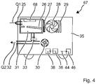
- Fig. 13 shows an embodiment of the well-flushing module 67.
- the well-flushing module 67 has a dust collector 26, a dust filter 27 and a fan 28, like the well-flushing modules previously described.
- the well flushing module 67 may generate an air flow Q1 for evacuating cuttings from the well.
- the borehole flushing module 67 can also generate an air flow Q2 for injecting fine-grained particles into the borehole.
- the borehole flushing module 67 uses the drill cuttings previously sucked into the dust collection container 26 as mineral, fine-grain particles.
- the dust collection container 26 thus serves at the same time as a dispenser 31.
- the sucked-in air flow Q1 is preferably cleaned of ferrous particles.
- the cleaning can be done by a magnet 68 .
- the magnet 68 is arranged near the intake port 25 , for example.
- the iron filings can adhere directly to the magnet 68 .
- the dust collection container 26 can have an area separated from the dispenser 31 for collecting ferrous material contaminated area.
- the magnet 68 can deflect the ferrous material M2 .
- the heavier metal can be separated by a centrifuge and a curved air duct.
- the illustrated embodiment uses a fan 28 and a blower 30 for the two air flows Q1, Q2.
- a fan can generate both air flows Q1, Q2 .
- the well flushing module 67 can be constructed according to the hand-held manner.
Landscapes
- Engineering & Computer Science (AREA)
- Mechanical Engineering (AREA)
- Percussive Tools And Related Accessories (AREA)
Claims (11)
- Procédé de commande d'un module de balayage de trou de perçage (2) destiné à un outil de perçage (5), ledit procédé comprenant les étapes suivantes :fournir des particules fines dans un distributeur (31),détecter, à l'aide d'un détecteur de matériau (37), un matériau (M) à un emplacement traité par l'outil (5) ;introduire les particules fines à l'emplacement traité par l'outil (5) lorsque le détecteur de matériau (37) détecte un matériau ferreux (M2) etaspirer un flux d'air (Q1) depuis l'emplacement traité par l'outil (5) au moyen d'un ventilateur (28) du module de balayage de trou de perçage (2) lorsque le détecteur de matériau (37) détecte un matériau essentiellement minéral (M1).
- Procédé de commande selon la revendication 1, caractérisé en ce que, lorsque le détecteur de matériau (37) détecte un matériau ferreux (M2), les particules fines sont introduites à l'emplacement traité dans un flux d'air (Q2) généré par une soufflante (30) du module de balayage de trou de perçage (2).
- Procédé de commande selon l'une des revendications précédentes, caractérisé en ce que les particules fines sont séparées du flux d'air (Q1) et amenées au distributeur (31).
- Procédé de commande selon la revendication 3, caractérisé en ce que les particules contenant du fer sont éliminées du flux d'air (Q1).
- Procédé de commande selon l'une des revendications précédentes, caractérisé en ce qu'une soupape de dosage (33) du distributeur (31) est fermée lorsque le détecteur de matériau (37) détecte un matériau minéral (M1), et la soupape de dosage (33) est ouverte lorsque le détecteur de matériau (37) détecte un matériau ferreux (M2).
- Procédé de commande selon l'une des revendications précédentes, caractérisé en ce que le détecteur de matériau (37) détecte les vibrations du module de balayage de trou de forage (2) ou les vibrations d'une machine-outil à main (1), dans laquelle l'outil de burinage (5) est utilisé, par le biais d'un capteur de vibrations (39) et une unité d'évaluation (40) détecte le matériau (M2) sur la base des vibrations.
- Procédé de commande selon la revendication 6, caractérisé en ce qu'une vibration supérieure à une valeur seuil est associée à un matériau ferreux (M2) et une vibration inférieure à la valeur seuil est associée à un matériau essentiellement minéral (M1).
- Module de balayage de trou de perçage (2) destiné à un outil de perçage (5) comprenant une soufflante (30) destinée à générer un flux d'air de soufflage (Q2), caractérisé parun distributeur commandable (31) destiné à délivrer des particules fines dans le flux d'air (Q2) généré par la soufflante (30),un détecteur de matériau (37) destiné à détecter le matériau (M) traité par l'outil (5), et une commande (36) qui, en réponse au matériau détecté par le détecteur de matériau (37), ferme le distributeur (31) lorsque le détecteur de matériau (37) détecte un matériau minéral (M1) et commute le distributeur (31) de manière à délivrer les particules fines lorsque le détecteur de matériau (37) détecte un matériau ferreux (M2).
- Module de balayage de trou de perçage (2) selon la revendication 8, caractérisé en ce que le détecteur de matériau (37) comporte un capteur de vibrations (39) destiné à détecter les vibrations et une unité d'évaluation (40) destinée à associer des vibrations supérieures à une valeur seuil à un matériau ferreux (M2) et des vibrations inférieures à une valeur seuil à un matériau minéral.
- Module de balayage de trou de perçage (2) selon l'une des revendications 8 ou 9, caractérisé par un récipient de récupération de poussières (26) et un filtre à poussières (27) et un ventilateur (28) destiné à générer un flux d'air d'aspiration (Q1), la soufflante (30) pouvant être commutée entre le flux d'air de soufflage (Q2) et le flux d'air d'aspiration (Q1).
- Machine-outil à main (1) comprenant un module de balayage de trou de perçage (55) selon l'une des revendications 8 à 9, caractérisée par un moteur électrique (9) et un mécanisme de percussion (6) entraîné par le moteur électrique (9).
Applications Claiming Priority (2)
| Application Number | Priority Date | Filing Date | Title |
|---|---|---|---|
| EP16194715.5A EP3311956A1 (fr) | 2016-10-20 | 2016-10-20 | Procédé de commande et module de rinçage de trou de forage |
| PCT/EP2017/076022 WO2018073092A1 (fr) | 2016-10-20 | 2017-10-12 | Procédé de commande et module de nettoyage de trou de forage |
Publications (2)
| Publication Number | Publication Date |
|---|---|
| EP3529006A1 EP3529006A1 (fr) | 2019-08-28 |
| EP3529006B1 true EP3529006B1 (fr) | 2023-01-11 |
Family
ID=57189832
Family Applications (2)
| Application Number | Title | Priority Date | Filing Date |
|---|---|---|---|
| EP16194715.5A Withdrawn EP3311956A1 (fr) | 2016-10-20 | 2016-10-20 | Procédé de commande et module de rinçage de trou de forage |
| EP17781134.6A Active EP3529006B1 (fr) | 2016-10-20 | 2017-10-12 | Procédé de commande et module de rinçage de trou de forage |
Family Applications Before (1)
| Application Number | Title | Priority Date | Filing Date |
|---|---|---|---|
| EP16194715.5A Withdrawn EP3311956A1 (fr) | 2016-10-20 | 2016-10-20 | Procédé de commande et module de rinçage de trou de forage |
Country Status (3)
| Country | Link |
|---|---|
| US (1) | US11123855B2 (fr) |
| EP (2) | EP3311956A1 (fr) |
| WO (1) | WO2018073092A1 (fr) |
Families Citing this family (3)
| Publication number | Priority date | Publication date | Assignee | Title |
|---|---|---|---|---|
| GB201616363D0 (en) * | 2016-09-27 | 2016-11-09 | Black & Decker Inc | Dust extractor with flat back |
| EP3311951A1 (fr) * | 2016-10-20 | 2018-04-25 | HILTI Aktiengesellschaft | Procédé de commande et module d'aspirateur |
| WO2020167875A1 (fr) * | 2019-02-15 | 2020-08-20 | Milwaukee Electric Tool Corporation | Ensemble outil électrique comprenant un collecteur de poussière |
Family Cites Families (10)
| Publication number | Priority date | Publication date | Assignee | Title |
|---|---|---|---|---|
| DE1192132B (de) * | 1960-11-18 | 1965-05-06 | Hermann Wacker, Peter Wacker, München | Bohr- und Aufbruchhammer mit Benzin- oder Elektromotor-Antrieb |
| FI94663C (fi) * | 1994-02-28 | 1995-10-10 | Tamrock | Sovitelma kallionporauslaitteen ohjauslaitteistosta |
| US6637522B2 (en) * | 1998-11-24 | 2003-10-28 | J. H. Fletcher & Co., Inc. | Enhanced computer control of in-situ drilling system |
| US6216800B1 (en) * | 1998-11-24 | 2001-04-17 | J. H. Fletcher & Co., Inc. | In-situ drilling system with dust collection and overload control |
| DE19960824C2 (de) | 1999-12-16 | 2003-08-21 | Hilti Ag | Verfahren und Einrichtung zur Untersuchung und Identifizierung der Art eines Untergrunds |
| DE102004035875B3 (de) * | 2004-07-23 | 2005-12-22 | Hilti Ag | Handbohrgerät mit Blaslufterzeuger |
| US8529169B2 (en) * | 2007-12-07 | 2013-09-10 | Hitachi Koki Co., Ltd. | Drilling tool with dust collector |
| JP5463464B2 (ja) * | 2010-04-12 | 2014-04-09 | Uht株式会社 | 穿孔装置 |
| JP5525963B2 (ja) | 2010-08-20 | 2014-06-18 | 株式会社マキタ | 集塵装置付き電動工具 |
| GB201616363D0 (en) * | 2016-09-27 | 2016-11-09 | Black & Decker Inc | Dust extractor with flat back |
-
2016
- 2016-10-20 EP EP16194715.5A patent/EP3311956A1/fr not_active Withdrawn
-
2017
- 2017-10-12 WO PCT/EP2017/076022 patent/WO2018073092A1/fr not_active Ceased
- 2017-10-12 US US16/341,389 patent/US11123855B2/en not_active Expired - Fee Related
- 2017-10-12 EP EP17781134.6A patent/EP3529006B1/fr active Active
Also Published As
| Publication number | Publication date |
|---|---|
| EP3529006A1 (fr) | 2019-08-28 |
| US11123855B2 (en) | 2021-09-21 |
| WO2018073092A1 (fr) | 2018-04-26 |
| US20200055173A1 (en) | 2020-02-20 |
| EP3311956A1 (fr) | 2018-04-25 |
Similar Documents
| Publication | Publication Date | Title |
|---|---|---|
| EP3529002B1 (fr) | Procédé de commande et module d'aspirateur | |
| DE10309012B3 (de) | Steuerverfahren einer axial schlagenden und drehenden Elektrohandwerkzeugmaschine | |
| EP3389935B1 (fr) | Procédé de commande et machine-outil portative | |
| US10759035B2 (en) | Suction extraction device | |
| WO2018073092A1 (fr) | Procédé de commande et module de nettoyage de trou de forage | |
| DE102004017939A1 (de) | Geführte Werkzeugmaschine sowie Verfahren zum Betreiben einer geführten Werkzeugmaschine | |
| EP3221088B1 (fr) | Procédé de commande d'une perceuse | |
| AU2017281678B2 (en) | Drilling apparatus and method for collecting research sample | |
| US6892834B1 (en) | Piloted drill barrel and method of using same | |
| EP1166970A2 (fr) | Outil électroportatif avec mécanisme de percussion | |
| KR101652991B1 (ko) | 암분 배출이 효과적으로 이루어지는 dth 방식의 천공기 및, 이를 이용한 천공방법 | |
| US5511628A (en) | Pneumatic drill with central evacuation outlet | |
| EP2592214A1 (fr) | Marteau perforateur pneumatique réutilisant la pression de l'air | |
| CN208323273U (zh) | 用于桥面或地面植筋钻孔的可移动式钻孔机 | |
| JP4533910B2 (ja) | 破砕削孔装置 | |
| CN210422462U (zh) | 冲击式螺旋输送钻机 | |
| EP3206839A1 (fr) | Machine-outil portative de burinage | |
| CN114211460B (zh) | 一种减震电锤 | |
| DE7023805U (de) | Staubauffangvorrichtung für Bohrmaschinen, Bohrhämmer oder dergleichen | |
| CN213947018U (zh) | 一种具有接渣功能的电钻及冲击工具 | |
| AU2016266110B2 (en) | A Reverse Circulation Down Hole Hammer | |
| EP3898117B1 (fr) | Machine-outil de burinage portative | |
| JPH11303561A (ja) | 掘削ビット | |
| SU829913A1 (ru) | Колонковый пневмоударный бур | |
| JPH09192431A (ja) | ドリリング装置のバグフィルタ |
Legal Events
| Date | Code | Title | Description |
|---|---|---|---|
| STAA | Information on the status of an ep patent application or granted ep patent |
Free format text: STATUS: UNKNOWN |
|
| STAA | Information on the status of an ep patent application or granted ep patent |
Free format text: STATUS: THE INTERNATIONAL PUBLICATION HAS BEEN MADE |
|
| PUAI | Public reference made under article 153(3) epc to a published international application that has entered the european phase |
Free format text: ORIGINAL CODE: 0009012 |
|
| STAA | Information on the status of an ep patent application or granted ep patent |
Free format text: STATUS: REQUEST FOR EXAMINATION WAS MADE |
|
| 17P | Request for examination filed |
Effective date: 20190520 |
|
| AK | Designated contracting states |
Kind code of ref document: A1 Designated state(s): AL AT BE BG CH CY CZ DE DK EE ES FI FR GB GR HR HU IE IS IT LI LT LU LV MC MK MT NL NO PL PT RO RS SE SI SK SM TR |
|
| AX | Request for extension of the european patent |
Extension state: BA ME |
|
| DAV | Request for validation of the european patent (deleted) | ||
| DAX | Request for extension of the european patent (deleted) | ||
| GRAP | Despatch of communication of intention to grant a patent |
Free format text: ORIGINAL CODE: EPIDOSNIGR1 |
|
| STAA | Information on the status of an ep patent application or granted ep patent |
Free format text: STATUS: GRANT OF PATENT IS INTENDED |
|
| INTG | Intention to grant announced |
Effective date: 20220902 |
|
| RIN1 | Information on inventor provided before grant (corrected) |
Inventor name: PETERS, CARSTEN Inventor name: WESSELER GEB. KAPS, HELENE Inventor name: BRUNNER, MICHAEL Inventor name: PLUEMACHER, BASTIAN Inventor name: BOHN, KLAUS-PETER Inventor name: HARTMANN, MARKUS |
|
| GRAS | Grant fee paid |
Free format text: ORIGINAL CODE: EPIDOSNIGR3 |
|
| GRAA | (expected) grant |
Free format text: ORIGINAL CODE: 0009210 |
|
| STAA | Information on the status of an ep patent application or granted ep patent |
Free format text: STATUS: THE PATENT HAS BEEN GRANTED |
|
| AK | Designated contracting states |
Kind code of ref document: B1 Designated state(s): AL AT BE BG CH CY CZ DE DK EE ES FI FR GB GR HR HU IE IS IT LI LT LU LV MC MK MT NL NO PL PT RO RS SE SI SK SM TR |
|
| REG | Reference to a national code |
Ref country code: GB Ref legal event code: FG4D Free format text: NOT ENGLISH |
|
| REG | Reference to a national code |
Ref country code: CH Ref legal event code: EP |
|
| REG | Reference to a national code |
Ref country code: DE Ref legal event code: R096 Ref document number: 502017014322 Country of ref document: DE |
|
| REG | Reference to a national code |
Ref country code: IE Ref legal event code: FG4D Free format text: LANGUAGE OF EP DOCUMENT: GERMAN |
|
| REG | Reference to a national code |
Ref country code: AT Ref legal event code: REF Ref document number: 1543129 Country of ref document: AT Kind code of ref document: T Effective date: 20230215 |
|
| REG | Reference to a national code |
Ref country code: LT Ref legal event code: MG9D |
|
| REG | Reference to a national code |
Ref country code: NL Ref legal event code: MP Effective date: 20230111 |
|
| PG25 | Lapsed in a contracting state [announced via postgrant information from national office to epo] |
Ref country code: NL Free format text: LAPSE BECAUSE OF FAILURE TO SUBMIT A TRANSLATION OF THE DESCRIPTION OR TO PAY THE FEE WITHIN THE PRESCRIBED TIME-LIMIT Effective date: 20230111 |
|
| PG25 | Lapsed in a contracting state [announced via postgrant information from national office to epo] |
Ref country code: RS Free format text: LAPSE BECAUSE OF FAILURE TO SUBMIT A TRANSLATION OF THE DESCRIPTION OR TO PAY THE FEE WITHIN THE PRESCRIBED TIME-LIMIT Effective date: 20230111 Ref country code: PT Free format text: LAPSE BECAUSE OF FAILURE TO SUBMIT A TRANSLATION OF THE DESCRIPTION OR TO PAY THE FEE WITHIN THE PRESCRIBED TIME-LIMIT Effective date: 20230511 Ref country code: NO Free format text: LAPSE BECAUSE OF FAILURE TO SUBMIT A TRANSLATION OF THE DESCRIPTION OR TO PAY THE FEE WITHIN THE PRESCRIBED TIME-LIMIT Effective date: 20230411 Ref country code: LV Free format text: LAPSE BECAUSE OF FAILURE TO SUBMIT A TRANSLATION OF THE DESCRIPTION OR TO PAY THE FEE WITHIN THE PRESCRIBED TIME-LIMIT Effective date: 20230111 Ref country code: LT Free format text: LAPSE BECAUSE OF FAILURE TO SUBMIT A TRANSLATION OF THE DESCRIPTION OR TO PAY THE FEE WITHIN THE PRESCRIBED TIME-LIMIT Effective date: 20230111 Ref country code: HR Free format text: LAPSE BECAUSE OF FAILURE TO SUBMIT A TRANSLATION OF THE DESCRIPTION OR TO PAY THE FEE WITHIN THE PRESCRIBED TIME-LIMIT Effective date: 20230111 Ref country code: ES Free format text: LAPSE BECAUSE OF FAILURE TO SUBMIT A TRANSLATION OF THE DESCRIPTION OR TO PAY THE FEE WITHIN THE PRESCRIBED TIME-LIMIT Effective date: 20230111 |
|
| PG25 | Lapsed in a contracting state [announced via postgrant information from national office to epo] |
Ref country code: SE Free format text: LAPSE BECAUSE OF FAILURE TO SUBMIT A TRANSLATION OF THE DESCRIPTION OR TO PAY THE FEE WITHIN THE PRESCRIBED TIME-LIMIT Effective date: 20230111 Ref country code: PL Free format text: LAPSE BECAUSE OF FAILURE TO SUBMIT A TRANSLATION OF THE DESCRIPTION OR TO PAY THE FEE WITHIN THE PRESCRIBED TIME-LIMIT Effective date: 20230111 Ref country code: IS Free format text: LAPSE BECAUSE OF FAILURE TO SUBMIT A TRANSLATION OF THE DESCRIPTION OR TO PAY THE FEE WITHIN THE PRESCRIBED TIME-LIMIT Effective date: 20230511 Ref country code: GR Free format text: LAPSE BECAUSE OF FAILURE TO SUBMIT A TRANSLATION OF THE DESCRIPTION OR TO PAY THE FEE WITHIN THE PRESCRIBED TIME-LIMIT Effective date: 20230412 Ref country code: FI Free format text: LAPSE BECAUSE OF FAILURE TO SUBMIT A TRANSLATION OF THE DESCRIPTION OR TO PAY THE FEE WITHIN THE PRESCRIBED TIME-LIMIT Effective date: 20230111 |
|
| REG | Reference to a national code |
Ref country code: DE Ref legal event code: R097 Ref document number: 502017014322 Country of ref document: DE |
|
| PG25 | Lapsed in a contracting state [announced via postgrant information from national office to epo] |
Ref country code: SM Free format text: LAPSE BECAUSE OF FAILURE TO SUBMIT A TRANSLATION OF THE DESCRIPTION OR TO PAY THE FEE WITHIN THE PRESCRIBED TIME-LIMIT Effective date: 20230111 Ref country code: RO Free format text: LAPSE BECAUSE OF FAILURE TO SUBMIT A TRANSLATION OF THE DESCRIPTION OR TO PAY THE FEE WITHIN THE PRESCRIBED TIME-LIMIT Effective date: 20230111 Ref country code: EE Free format text: LAPSE BECAUSE OF FAILURE TO SUBMIT A TRANSLATION OF THE DESCRIPTION OR TO PAY THE FEE WITHIN THE PRESCRIBED TIME-LIMIT Effective date: 20230111 Ref country code: DK Free format text: LAPSE BECAUSE OF FAILURE TO SUBMIT A TRANSLATION OF THE DESCRIPTION OR TO PAY THE FEE WITHIN THE PRESCRIBED TIME-LIMIT Effective date: 20230111 Ref country code: CZ Free format text: LAPSE BECAUSE OF FAILURE TO SUBMIT A TRANSLATION OF THE DESCRIPTION OR TO PAY THE FEE WITHIN THE PRESCRIBED TIME-LIMIT Effective date: 20230111 |
|
| PLBE | No opposition filed within time limit |
Free format text: ORIGINAL CODE: 0009261 |
|
| STAA | Information on the status of an ep patent application or granted ep patent |
Free format text: STATUS: NO OPPOSITION FILED WITHIN TIME LIMIT |
|
| PG25 | Lapsed in a contracting state [announced via postgrant information from national office to epo] |
Ref country code: SK Free format text: LAPSE BECAUSE OF FAILURE TO SUBMIT A TRANSLATION OF THE DESCRIPTION OR TO PAY THE FEE WITHIN THE PRESCRIBED TIME-LIMIT Effective date: 20230111 |
|
| 26N | No opposition filed |
Effective date: 20231012 |
|
| PG25 | Lapsed in a contracting state [announced via postgrant information from national office to epo] |
Ref country code: SI Free format text: LAPSE BECAUSE OF FAILURE TO SUBMIT A TRANSLATION OF THE DESCRIPTION OR TO PAY THE FEE WITHIN THE PRESCRIBED TIME-LIMIT Effective date: 20230111 |
|
| PG25 | Lapsed in a contracting state [announced via postgrant information from national office to epo] |
Ref country code: IT Free format text: LAPSE BECAUSE OF FAILURE TO SUBMIT A TRANSLATION OF THE DESCRIPTION OR TO PAY THE FEE WITHIN THE PRESCRIBED TIME-LIMIT Effective date: 20230111 Ref country code: MC Free format text: LAPSE BECAUSE OF FAILURE TO SUBMIT A TRANSLATION OF THE DESCRIPTION OR TO PAY THE FEE WITHIN THE PRESCRIBED TIME-LIMIT Effective date: 20230111 |
|
| REG | Reference to a national code |
Ref country code: CH Ref legal event code: PL |
|
| REG | Reference to a national code |
Ref country code: BE Ref legal event code: MM Effective date: 20231031 |
|
| PG25 | Lapsed in a contracting state [announced via postgrant information from national office to epo] |
Ref country code: LU Free format text: LAPSE BECAUSE OF NON-PAYMENT OF DUE FEES Effective date: 20231012 |
|
| PG25 | Lapsed in a contracting state [announced via postgrant information from national office to epo] |
Ref country code: LU Free format text: LAPSE BECAUSE OF NON-PAYMENT OF DUE FEES Effective date: 20231012 |
|
| PG25 | Lapsed in a contracting state [announced via postgrant information from national office to epo] |
Ref country code: CH Free format text: LAPSE BECAUSE OF NON-PAYMENT OF DUE FEES Effective date: 20231031 |
|
| PG25 | Lapsed in a contracting state [announced via postgrant information from national office to epo] |
Ref country code: CH Free format text: LAPSE BECAUSE OF NON-PAYMENT OF DUE FEES Effective date: 20231031 |
|
| PG25 | Lapsed in a contracting state [announced via postgrant information from national office to epo] |
Ref country code: BE Free format text: LAPSE BECAUSE OF NON-PAYMENT OF DUE FEES Effective date: 20231031 |
|
| PG25 | Lapsed in a contracting state [announced via postgrant information from national office to epo] |
Ref country code: IE Free format text: LAPSE BECAUSE OF NON-PAYMENT OF DUE FEES Effective date: 20231012 |
|
| PG25 | Lapsed in a contracting state [announced via postgrant information from national office to epo] |
Ref country code: IE Free format text: LAPSE BECAUSE OF NON-PAYMENT OF DUE FEES Effective date: 20231012 |
|
| PG25 | Lapsed in a contracting state [announced via postgrant information from national office to epo] |
Ref country code: BG Free format text: LAPSE BECAUSE OF FAILURE TO SUBMIT A TRANSLATION OF THE DESCRIPTION OR TO PAY THE FEE WITHIN THE PRESCRIBED TIME-LIMIT Effective date: 20230111 |
|
| PG25 | Lapsed in a contracting state [announced via postgrant information from national office to epo] |
Ref country code: BG Free format text: LAPSE BECAUSE OF FAILURE TO SUBMIT A TRANSLATION OF THE DESCRIPTION OR TO PAY THE FEE WITHIN THE PRESCRIBED TIME-LIMIT Effective date: 20230111 |
|
| REG | Reference to a national code |
Ref country code: AT Ref legal event code: MM01 Ref document number: 1543129 Country of ref document: AT Kind code of ref document: T Effective date: 20231012 |
|
| PGFP | Annual fee paid to national office [announced via postgrant information from national office to epo] |
Ref country code: DE Payment date: 20241021 Year of fee payment: 8 |
|
| PGFP | Annual fee paid to national office [announced via postgrant information from national office to epo] |
Ref country code: GB Payment date: 20241025 Year of fee payment: 8 |
|
| PG25 | Lapsed in a contracting state [announced via postgrant information from national office to epo] |
Ref country code: AT Free format text: LAPSE BECAUSE OF NON-PAYMENT OF DUE FEES Effective date: 20231012 |
|
| PGFP | Annual fee paid to national office [announced via postgrant information from national office to epo] |
Ref country code: FR Payment date: 20241030 Year of fee payment: 8 |
|
| PG25 | Lapsed in a contracting state [announced via postgrant information from national office to epo] |
Ref country code: AT Free format text: LAPSE BECAUSE OF NON-PAYMENT OF DUE FEES Effective date: 20231012 |
|
| PG25 | Lapsed in a contracting state [announced via postgrant information from national office to epo] |
Ref country code: CY Free format text: LAPSE BECAUSE OF FAILURE TO SUBMIT A TRANSLATION OF THE DESCRIPTION OR TO PAY THE FEE WITHIN THE PRESCRIBED TIME-LIMIT; INVALID AB INITIO Effective date: 20171012 |
|
| PG25 | Lapsed in a contracting state [announced via postgrant information from national office to epo] |
Ref country code: HU Free format text: LAPSE BECAUSE OF FAILURE TO SUBMIT A TRANSLATION OF THE DESCRIPTION OR TO PAY THE FEE WITHIN THE PRESCRIBED TIME-LIMIT; INVALID AB INITIO Effective date: 20171012 |
|
| PG25 | Lapsed in a contracting state [announced via postgrant information from national office to epo] |
Ref country code: TR Free format text: LAPSE BECAUSE OF FAILURE TO SUBMIT A TRANSLATION OF THE DESCRIPTION OR TO PAY THE FEE WITHIN THE PRESCRIBED TIME-LIMIT Effective date: 20230111 |