EP3529052B1 - Sonotrode und amboss zum ultraschallschweissen von kunststoffen, verfahren zur herstellung eines kunststoffbehälters - Google Patents
Sonotrode und amboss zum ultraschallschweissen von kunststoffen, verfahren zur herstellung eines kunststoffbehälters Download PDFInfo
- Publication number
- EP3529052B1 EP3529052B1 EP17800608.6A EP17800608A EP3529052B1 EP 3529052 B1 EP3529052 B1 EP 3529052B1 EP 17800608 A EP17800608 A EP 17800608A EP 3529052 B1 EP3529052 B1 EP 3529052B1
- Authority
- EP
- European Patent Office
- Prior art keywords
- aforesaid
- anvil
- sonotrode
- plastic container
- welding contact
- Prior art date
- Legal status (The legal status is an assumption and is not a legal conclusion. Google has not performed a legal analysis and makes no representation as to the accuracy of the status listed.)
- Active
Links
Images









Classifications
-
- B—PERFORMING OPERATIONS; TRANSPORTING
- B29—WORKING OF PLASTICS; WORKING OF SUBSTANCES IN A PLASTIC STATE IN GENERAL
- B29C—SHAPING OR JOINING OF PLASTICS; SHAPING OF MATERIAL IN A PLASTIC STATE, NOT OTHERWISE PROVIDED FOR; AFTER-TREATMENT OF THE SHAPED PRODUCTS, e.g. REPAIRING
- B29C65/00—Joining or sealing of preformed parts, e.g. welding of plastics materials; Apparatus therefor
- B29C65/02—Joining or sealing of preformed parts, e.g. welding of plastics materials; Apparatus therefor by heating, with or without pressure
- B29C65/08—Joining or sealing of preformed parts, e.g. welding of plastics materials; Apparatus therefor by heating, with or without pressure using ultrasonic vibrations
-
- B—PERFORMING OPERATIONS; TRANSPORTING
- B29—WORKING OF PLASTICS; WORKING OF SUBSTANCES IN A PLASTIC STATE IN GENERAL
- B29C—SHAPING OR JOINING OF PLASTICS; SHAPING OF MATERIAL IN A PLASTIC STATE, NOT OTHERWISE PROVIDED FOR; AFTER-TREATMENT OF THE SHAPED PRODUCTS, e.g. REPAIRING
- B29C66/00—General aspects of processes or apparatus for joining preformed parts
- B29C66/01—General aspects dealing with the joint area or with the area to be joined
- B29C66/05—Particular design of joint configurations
- B29C66/10—Particular design of joint configurations particular design of the joint cross-sections
- B29C66/11—Joint cross-sections comprising a single joint-segment, i.e. one of the parts to be joined comprising a single joint-segment in the joint cross-section
- B29C66/112—Single lapped joints
- B29C66/1122—Single lap to lap joints, i.e. overlap joints
-
- B—PERFORMING OPERATIONS; TRANSPORTING
- B29—WORKING OF PLASTICS; WORKING OF SUBSTANCES IN A PLASTIC STATE IN GENERAL
- B29C—SHAPING OR JOINING OF PLASTICS; SHAPING OF MATERIAL IN A PLASTIC STATE, NOT OTHERWISE PROVIDED FOR; AFTER-TREATMENT OF THE SHAPED PRODUCTS, e.g. REPAIRING
- B29C66/00—General aspects of processes or apparatus for joining preformed parts
- B29C66/01—General aspects dealing with the joint area or with the area to be joined
- B29C66/05—Particular design of joint configurations
- B29C66/20—Particular design of joint configurations particular design of the joint lines, e.g. of the weld lines
- B29C66/23—Particular design of joint configurations particular design of the joint lines, e.g. of the weld lines said joint lines being multiple and parallel or being in the form of tessellations
- B29C66/232—Particular design of joint configurations particular design of the joint lines, e.g. of the weld lines said joint lines being multiple and parallel or being in the form of tessellations said joint lines being multiple and parallel, i.e. the joint being formed by several parallel joint lines
-
- B—PERFORMING OPERATIONS; TRANSPORTING
- B29—WORKING OF PLASTICS; WORKING OF SUBSTANCES IN A PLASTIC STATE IN GENERAL
- B29C—SHAPING OR JOINING OF PLASTICS; SHAPING OF MATERIAL IN A PLASTIC STATE, NOT OTHERWISE PROVIDED FOR; AFTER-TREATMENT OF THE SHAPED PRODUCTS, e.g. REPAIRING
- B29C66/00—General aspects of processes or apparatus for joining preformed parts
- B29C66/40—General aspects of joining substantially flat articles, e.g. plates, sheets or web-like materials; Making flat seams in tubular or hollow articles; Joining single elements to substantially flat surfaces
- B29C66/41—Joining substantially flat articles ; Making flat seams in tubular or hollow articles
- B29C66/43—Joining a relatively small portion of the surface of said articles
- B29C66/431—Joining the articles to themselves
- B29C66/4312—Joining the articles to themselves for making flat seams in tubular or hollow articles, e.g. transversal seams
- B29C66/43121—Closing the ends of tubular or hollow single articles, e.g. closing the ends of bags
- B29C66/43123—Closing the ends of squeeze tubes, e.g. for toothpaste or cosmetics
-
- B—PERFORMING OPERATIONS; TRANSPORTING
- B29—WORKING OF PLASTICS; WORKING OF SUBSTANCES IN A PLASTIC STATE IN GENERAL
- B29C—SHAPING OR JOINING OF PLASTICS; SHAPING OF MATERIAL IN A PLASTIC STATE, NOT OTHERWISE PROVIDED FOR; AFTER-TREATMENT OF THE SHAPED PRODUCTS, e.g. REPAIRING
- B29C66/00—General aspects of processes or apparatus for joining preformed parts
- B29C66/80—General aspects of machine operations or constructions and parts thereof
- B29C66/81—General aspects of the pressing elements, i.e. the elements applying pressure on the parts to be joined in the area to be joined, e.g. the welding jaws or clamps
- B29C66/814—General aspects of the pressing elements, i.e. the elements applying pressure on the parts to be joined in the area to be joined, e.g. the welding jaws or clamps characterised by the design of the pressing elements, e.g. of the welding jaws or clamps
- B29C66/8141—General aspects of the pressing elements, i.e. the elements applying pressure on the parts to be joined in the area to be joined, e.g. the welding jaws or clamps characterised by the design of the pressing elements, e.g. of the welding jaws or clamps characterised by the surface geometry of the part of the pressing elements, e.g. welding jaws or clamps, coming into contact with the parts to be joined
- B29C66/81433—General aspects of the pressing elements, i.e. the elements applying pressure on the parts to be joined in the area to be joined, e.g. the welding jaws or clamps characterised by the design of the pressing elements, e.g. of the welding jaws or clamps characterised by the surface geometry of the part of the pressing elements, e.g. welding jaws or clamps, coming into contact with the parts to be joined being toothed, i.e. comprising several teeth or pins, or being patterned
-
- B—PERFORMING OPERATIONS; TRANSPORTING
- B29—WORKING OF PLASTICS; WORKING OF SUBSTANCES IN A PLASTIC STATE IN GENERAL
- B29C—SHAPING OR JOINING OF PLASTICS; SHAPING OF MATERIAL IN A PLASTIC STATE, NOT OTHERWISE PROVIDED FOR; AFTER-TREATMENT OF THE SHAPED PRODUCTS, e.g. REPAIRING
- B29C66/00—General aspects of processes or apparatus for joining preformed parts
- B29C66/80—General aspects of machine operations or constructions and parts thereof
- B29C66/83—General aspects of machine operations or constructions and parts thereof characterised by the movement of the joining or pressing tools
- B29C66/832—Reciprocating joining or pressing tools
- B29C66/8322—Joining or pressing tools reciprocating along one axis
- B29C66/83221—Joining or pressing tools reciprocating along one axis cooperating reciprocating tools, each tool reciprocating along one axis
-
- B—PERFORMING OPERATIONS; TRANSPORTING
- B29—WORKING OF PLASTICS; WORKING OF SUBSTANCES IN A PLASTIC STATE IN GENERAL
- B29C—SHAPING OR JOINING OF PLASTICS; SHAPING OF MATERIAL IN A PLASTIC STATE, NOT OTHERWISE PROVIDED FOR; AFTER-TREATMENT OF THE SHAPED PRODUCTS, e.g. REPAIRING
- B29C66/00—General aspects of processes or apparatus for joining preformed parts
- B29C66/80—General aspects of machine operations or constructions and parts thereof
- B29C66/84—Specific machine types or machines suitable for specific applications
- B29C66/849—Packaging machines
-
- B—PERFORMING OPERATIONS; TRANSPORTING
- B29—WORKING OF PLASTICS; WORKING OF SUBSTANCES IN A PLASTIC STATE IN GENERAL
- B29C—SHAPING OR JOINING OF PLASTICS; SHAPING OF MATERIAL IN A PLASTIC STATE, NOT OTHERWISE PROVIDED FOR; AFTER-TREATMENT OF THE SHAPED PRODUCTS, e.g. REPAIRING
- B29C66/00—General aspects of processes or apparatus for joining preformed parts
- B29C66/01—General aspects dealing with the joint area or with the area to be joined
- B29C66/05—Particular design of joint configurations
- B29C66/20—Particular design of joint configurations particular design of the joint lines, e.g. of the weld lines
- B29C66/21—Particular design of joint configurations particular design of the joint lines, e.g. of the weld lines said joint lines being formed by a single dot or dash or by several dots or dashes, i.e. spot joining or spot welding
-
- B—PERFORMING OPERATIONS; TRANSPORTING
- B29—WORKING OF PLASTICS; WORKING OF SUBSTANCES IN A PLASTIC STATE IN GENERAL
- B29C—SHAPING OR JOINING OF PLASTICS; SHAPING OF MATERIAL IN A PLASTIC STATE, NOT OTHERWISE PROVIDED FOR; AFTER-TREATMENT OF THE SHAPED PRODUCTS, e.g. REPAIRING
- B29C66/00—General aspects of processes or apparatus for joining preformed parts
- B29C66/70—General aspects of processes or apparatus for joining preformed parts characterised by the composition, physical properties or the structure of the material of the parts to be joined; Joining with non-plastics material
- B29C66/71—General aspects of processes or apparatus for joining preformed parts characterised by the composition, physical properties or the structure of the material of the parts to be joined; Joining with non-plastics material characterised by the composition of the plastics material of the parts to be joined
-
- B—PERFORMING OPERATIONS; TRANSPORTING
- B29—WORKING OF PLASTICS; WORKING OF SUBSTANCES IN A PLASTIC STATE IN GENERAL
- B29C—SHAPING OR JOINING OF PLASTICS; SHAPING OF MATERIAL IN A PLASTIC STATE, NOT OTHERWISE PROVIDED FOR; AFTER-TREATMENT OF THE SHAPED PRODUCTS, e.g. REPAIRING
- B29C66/00—General aspects of processes or apparatus for joining preformed parts
- B29C66/70—General aspects of processes or apparatus for joining preformed parts characterised by the composition, physical properties or the structure of the material of the parts to be joined; Joining with non-plastics material
- B29C66/72—General aspects of processes or apparatus for joining preformed parts characterised by the composition, physical properties or the structure of the material of the parts to be joined; Joining with non-plastics material characterised by the structure of the material of the parts to be joined
- B29C66/723—General aspects of processes or apparatus for joining preformed parts characterised by the composition, physical properties or the structure of the material of the parts to be joined; Joining with non-plastics material characterised by the structure of the material of the parts to be joined being multi-layered
-
- B—PERFORMING OPERATIONS; TRANSPORTING
- B29—WORKING OF PLASTICS; WORKING OF SUBSTANCES IN A PLASTIC STATE IN GENERAL
- B29C—SHAPING OR JOINING OF PLASTICS; SHAPING OF MATERIAL IN A PLASTIC STATE, NOT OTHERWISE PROVIDED FOR; AFTER-TREATMENT OF THE SHAPED PRODUCTS, e.g. REPAIRING
- B29C66/00—General aspects of processes or apparatus for joining preformed parts
- B29C66/70—General aspects of processes or apparatus for joining preformed parts characterised by the composition, physical properties or the structure of the material of the parts to be joined; Joining with non-plastics material
- B29C66/72—General aspects of processes or apparatus for joining preformed parts characterised by the composition, physical properties or the structure of the material of the parts to be joined; Joining with non-plastics material characterised by the structure of the material of the parts to be joined
- B29C66/723—General aspects of processes or apparatus for joining preformed parts characterised by the composition, physical properties or the structure of the material of the parts to be joined; Joining with non-plastics material characterised by the structure of the material of the parts to be joined being multi-layered
- B29C66/7234—General aspects of processes or apparatus for joining preformed parts characterised by the composition, physical properties or the structure of the material of the parts to be joined; Joining with non-plastics material characterised by the structure of the material of the parts to be joined being multi-layered comprising a barrier layer
-
- B—PERFORMING OPERATIONS; TRANSPORTING
- B29—WORKING OF PLASTICS; WORKING OF SUBSTANCES IN A PLASTIC STATE IN GENERAL
- B29C—SHAPING OR JOINING OF PLASTICS; SHAPING OF MATERIAL IN A PLASTIC STATE, NOT OTHERWISE PROVIDED FOR; AFTER-TREATMENT OF THE SHAPED PRODUCTS, e.g. REPAIRING
- B29C66/00—General aspects of processes or apparatus for joining preformed parts
- B29C66/70—General aspects of processes or apparatus for joining preformed parts characterised by the composition, physical properties or the structure of the material of the parts to be joined; Joining with non-plastics material
- B29C66/72—General aspects of processes or apparatus for joining preformed parts characterised by the composition, physical properties or the structure of the material of the parts to be joined; Joining with non-plastics material characterised by the structure of the material of the parts to be joined
- B29C66/723—General aspects of processes or apparatus for joining preformed parts characterised by the composition, physical properties or the structure of the material of the parts to be joined; Joining with non-plastics material characterised by the structure of the material of the parts to be joined being multi-layered
- B29C66/7234—General aspects of processes or apparatus for joining preformed parts characterised by the composition, physical properties or the structure of the material of the parts to be joined; Joining with non-plastics material characterised by the structure of the material of the parts to be joined being multi-layered comprising a barrier layer
- B29C66/72341—General aspects of processes or apparatus for joining preformed parts characterised by the composition, physical properties or the structure of the material of the parts to be joined; Joining with non-plastics material characterised by the structure of the material of the parts to be joined being multi-layered comprising a barrier layer for gases
-
- B—PERFORMING OPERATIONS; TRANSPORTING
- B29—WORKING OF PLASTICS; WORKING OF SUBSTANCES IN A PLASTIC STATE IN GENERAL
- B29C—SHAPING OR JOINING OF PLASTICS; SHAPING OF MATERIAL IN A PLASTIC STATE, NOT OTHERWISE PROVIDED FOR; AFTER-TREATMENT OF THE SHAPED PRODUCTS, e.g. REPAIRING
- B29C66/00—General aspects of processes or apparatus for joining preformed parts
- B29C66/70—General aspects of processes or apparatus for joining preformed parts characterised by the composition, physical properties or the structure of the material of the parts to be joined; Joining with non-plastics material
- B29C66/73—General aspects of processes or apparatus for joining preformed parts characterised by the composition, physical properties or the structure of the material of the parts to be joined; Joining with non-plastics material characterised by the intensive physical properties of the material of the parts to be joined, by the optical properties of the material of the parts to be joined, by the extensive physical properties of the parts to be joined, by the state of the material of the parts to be joined or by the material of the parts to be joined being a thermoplastic or a thermoset
- B29C66/739—General aspects of processes or apparatus for joining preformed parts characterised by the composition, physical properties or the structure of the material of the parts to be joined; Joining with non-plastics material characterised by the intensive physical properties of the material of the parts to be joined, by the optical properties of the material of the parts to be joined, by the extensive physical properties of the parts to be joined, by the state of the material of the parts to be joined or by the material of the parts to be joined being a thermoplastic or a thermoset characterised by the material of the parts to be joined being a thermoplastic or a thermoset
- B29C66/7392—General aspects of processes or apparatus for joining preformed parts characterised by the composition, physical properties or the structure of the material of the parts to be joined; Joining with non-plastics material characterised by the intensive physical properties of the material of the parts to be joined, by the optical properties of the material of the parts to be joined, by the extensive physical properties of the parts to be joined, by the state of the material of the parts to be joined or by the material of the parts to be joined being a thermoplastic or a thermoset characterised by the material of the parts to be joined being a thermoplastic or a thermoset characterised by the material of at least one of the parts being a thermoplastic
- B29C66/73921—General aspects of processes or apparatus for joining preformed parts characterised by the composition, physical properties or the structure of the material of the parts to be joined; Joining with non-plastics material characterised by the intensive physical properties of the material of the parts to be joined, by the optical properties of the material of the parts to be joined, by the extensive physical properties of the parts to be joined, by the state of the material of the parts to be joined or by the material of the parts to be joined being a thermoplastic or a thermoset characterised by the material of the parts to be joined being a thermoplastic or a thermoset characterised by the material of at least one of the parts being a thermoplastic characterised by the materials of both parts being thermoplastics
-
- B—PERFORMING OPERATIONS; TRANSPORTING
- B29—WORKING OF PLASTICS; WORKING OF SUBSTANCES IN A PLASTIC STATE IN GENERAL
- B29D—PRODUCING PARTICULAR ARTICLES FROM PLASTICS OR FROM SUBSTANCES IN A PLASTIC STATE
- B29D23/00—Producing tubular articles
- B29D23/20—Flexible squeeze tubes, e.g. for cosmetics
-
- B—PERFORMING OPERATIONS; TRANSPORTING
- B29—WORKING OF PLASTICS; WORKING OF SUBSTANCES IN A PLASTIC STATE IN GENERAL
- B29L—INDEXING SCHEME ASSOCIATED WITH SUBCLASS B29C, RELATING TO PARTICULAR ARTICLES
- B29L2023/00—Tubular articles
- B29L2023/20—Flexible squeeze tubes, e.g. for cosmetics
Definitions
- the present invention relates to a combination of a sonotrode and an anvil for ultrasonic welding of a plastic container, and to a method for producing a plastic container, preferably a tube, comprising at least one ultrasonically-welded seal, and to a method for filling the plastic container.
- the present invention relates to stretch blown plastic containers.
- thermoplastic plastics can, largely, be divided into two categories, i.e. thermoplastic plastics and thermoset plastics.
- a thermoset plastic also referred to as a thermosetting or thermoset polymer, comprises polymers that can be melted once into a particular form, after which the curing precludes any further melting step.
- thermoplastic plastics also referred to as thermoplastics, can be repeatedly softened or even melted.
- Thermoplastics can be further divided into amorphous and semi-crystalline thermoplastics.
- amorphous thermoplastics are acrylonitrile-butadienestyrene (ABS), acrylic, polyvinylchloride (PVC) and polycarbonate (PC).
- ABS acrylonitrile-butadienestyrene
- PVC polyvinylchloride
- PC polycarbonate
- semi-crystalline thermoplastic materials are polyethylene/polythene (PE), polypropylene (PP), polyamide (PA) and polyester.
- ultrasonic welding allows thermoplastic plastics to be joined together. With ultrasonic welding mechanical vibrations are converted into heat as a result of which the plastic layers undergo molecular melting, whereby the plastics are placed between an anvil and a sonotrode.
- Tubes known as flexible plastic containers, are typically made from PE (high density), or via an injection moulding process whereby the filled tube is sealed as a whole, or in two steps whereby first a pipe is extruded, and the cap is sealed with the mouth. In a second step both parts are then welded together to form a tube.
- PE high density
- both parts are then welded together to form a tube.
- the disadvantage of these methods and materials is the lack of transparency given that it is not possible to extrude PE as a crystal-clear material.
- customisation of the tube via extrusion or injection moulding is limited. With filling also, there are a number of disadvantages given that after filling the tube has a hot stamp applied meaning that it cannot be filled to a sufficient height.
- a disadvantage of flexible plastic containers, preferably tubes, produced by a method comprising a step of stretch blowing, as in injection stretch blowing moulding (ISBM), is that these flexible plastic containers, preferably tubes, exhibit a relatively large concentric wall thickness difference.
- welding techniques for sealing flexible plastic containers, preferably tubes, i.e. using a hot stamp
- use is made in the main of flat pressing systems for sealing off the flexible plastic containers, preferably tubes.
- EP0242480A2 describes an ultrasonic welding unit with a sonotrode and an anvil on the protrusions from its flat upper surfaces with slanted sides.
- DE102010039003A1 describes a facility that welds and embosses a workpiece in a single operation.
- EP2804247A1 describes a welding unit with a pressure vibrator and a jig receiver positioned to face the pressure vibrator. In the latter welding unit, the pressure vibrator and the jig receiver hold the part to be welded and place this under pressure, while an ultrasonic vibration is applied.
- the pressure vibrator and the jig receiver have irregular work contact faces with projections that are chamfered and must face each other in order to create a very small pressurised area that breaks the heat-resistant layers amongst the object to be welded. Consequently, the only possible weld seam structure is achieved by placing the projections on the pressure vibrator and the jig receiver opposite each other.
- a disadvantage of these welding units is that they do not allow an effective and strong weld seam to be obtained.
- US2015090405 discloses ultrasonic welding of plastic films. It is silent on the welding of a blow-moulded surface of a plastic container, which exhibit relatively large concentric wall thickness differences.
- WO9529806 A2 discloses the use of ultrasonic welding for the sealing of the containers made by blow moulding.
- an object of the invention is to provide a combination of a sonotrode and anvil in order to effectively weld plastic layers.
- an object of the invention is to provide a plastic container, preferably a tube, which can offer greater resistance to splitting of the weld seam as a result of external pressure changes.
- Another object of the invention according to at least one of the embodiments is to provide a method for producing a plastic container, preferably a tube, comprising an ultrasonic welding step.
- Another object of the invention according to at least one of the embodiments is to provide a filling method for the plastic container, preferably a tube, whereby a sufficiently large volume of the plastic container can be filled.
- the object of the present invention is to provide a solution that meets the aforesaid needs.
- the present invention provides for a combination of a sonotrode and an anvil whereby aforesaid sonotrode for ultrasonic welding of a plastic container on at least one part of a blow-moulded surface of aforesaid plastic container, comprises
- Aforesaid sonotrode welding contact element is positioned in relation to aforesaid anvil welding contact element such that aforesaid sonotrode welding contact element is positioned during welding next to aforesaid anvil welding contact element and is provided to form each at least one part of a weld seam.
- a combination of a sonotrode and an anvil as described above has the advantage of providing a weld seam structure in the plastic layers to be welded that reduces the likelihood of splitting of the weld seam in the event of sudden or other pressure changes, for example if a plastic container falls under force of gravity.
- a combination of a sonotrode according to the invention and an anvil according to the invention whereby aforesaid sonotrode welding contact element is positioned in relation to aforesaid anvil welding contact element such that aforesaid sonotrode welding contact element is positioned during welding next to aforesaid anvil welding contact element provided to form each at least one part of a weld seam.
- aforesaid sonotrode welding contact element is positioned in relation to aforesaid anvil welding contact element such that aforesaid sonotrode welding contact element is positioned during welding next to aforesaid anvil welding contact element provided to form each at least one part of a weld seam.
- An advantage of this embodiment is that the alternate alignment of the sonotrode and anvil welding contact elements, or the alternating positioning of sonotrode and anvil welding contact elements such that the space between two neighbouring sonotrode welding contact elements can be filled with an anvil welding contact element whenever the sonotrode and the anvil move towards each other, increases the welding contact surface between the plastic layers to be welded and the welding contact elements. As a consequence, a stronger weld seam is obtained.
- aforesaid first substantially straight surface and aforesaid first plateau surface of aforesaid sonotrode welding contact element define an angle theta, whereby theta is situated in the range 75° to 90°, preferably in the range 82° to 88°.
- aforesaid sonotrode welding contact element defines a first height H1 and a first width B1, whereby aforesaid first height H1 is at least bigger than aforesaid first width B1, preferably at least bigger than twice aforesaid first width B1.
- the first height H1 of a sonotrode welding contact element is measured as the shortest distance between the sonotrode surface and the midpoint of the first plateau surface of the sonotrode welding contact element.
- the first width B1 is measured as the smallest distance between two opposing first lateral surfaces measured at a height equal to 30% of the first height H1 measured from the sonotrode surface on which the sonotrode welding contact element is positioned.
- the size of aforesaid first plateau surface of aforesaid sonotrode welding contact element is smaller than 25 mm 2 , preferably smaller than 10 mm 2 , and more particularly smaller than 1 mm 2 .
- aforesaid second substantially straight surface and aforesaid second plateau surface of aforesaid anvil welding contact element define an angle gamma, whereby gamma is situated in the range 75° to 90°, preferably in the range 82° to 88°.
- aforesaid anvil welding contact element defines a second height H2 and a second width B2, whereby aforesaid second height H2 is at least bigger than aforesaid second width B2, preferably at least bigger than twice aforesaid second width B2.
- the second height H2 of an anvil welding contact element is measured as the shortest distance between the anvil surface and the midpoint of the second plateau surface of the anvil welding contact element.
- the second width B2 is measured as the smallest distance between two opposing second lateral surfaces measured at a height equal to 30% of the second height H2 measured from the anvil surface on which the anvil welding contact element is positioned.
- the size of aforesaid second plateau surface of aforesaid anvil welding contact element is smaller than 25 mm 2 , preferably smaller than 10 mm 2 , and more particularly smaller than 1 mm 2 .
- aforesaid first row of ultrasonic welding contact elements is positioned directly opposite aforesaid first row of anvil welding contact elements.
- An advantageous aspect of this embodiment is that the weld seam formed has a weld structure that is substantially uniform whereby the strength of the weld seam is less dependent on position.
- the ratio of H1 to B1 is the same as the ratio H2 to B2. This embodiment allows the sonotrode and anvil welding contact elements to penetrate evenly into the plastic layers to be welded whereby the strength of the weld seam is less dependent on position.
- a method for producing a plastic container comprising at least one step of ultrasonic welding of aforesaid plastic container for the forming of a weld seam according to a weld section on at least one part of a blow-moulded surface of aforesaid plastic container to provide aforesaid plastic container with at least one seal, whereby aforesaid step of ultrasonic welding is carried out by aforesaid combination according to the invention.
- the inventors have, surprisingly, found that plastic containers produced by aforesaid method have a strong weld seam structure whereby the likelihood of splitting of the weld seam in the event of sudden or other pressure changes is reduced.
- aforesaid method during the step of ultrasonic welding comprises the steps of determining aforesaid weld section on aforesaid blow-moulded surface of aforesaid plastic container, clamping aforesaid plastic container between aforesaid sonotrode and/or aforesaid anvil, preferably between the combination, whereby aforesaid welding contact elements are joined with at least one part of aforesaid weld section, and forming of aforesaid weld seam.
- aforesaid method for producing a plastic container further comprises the steps of injection moulding a plastic container preform that can be extended biaxially, i.e. along two axes perpendicular with one another, whereby aforesaid plastic container preform comprises an open mouth and a sealed bottom, whereby aforesaid open mouth is positioned opposite aforesaid sealed bottom, and stretch blowing of aforesaid biaxially extendable plastic container preform in a blow mould, whereby aforesaid plastic container preform expands biaxially in aforesaid blow mould into aforesaid plastic container comprising aforesaid blow-moulded surface that is to be at least in part ultrasonically welded.
- the method comprises a step of embossing aforesaid blow-moulded surface during aforesaid step of stretch blowing, whereby aforesaid step of embossing is carried out in aforesaid blow mould comprising at least plate, preferably an etched plate.
- the method further comprises a step of cutting aforesaid plastic container, whereby aforesaid step of cutting is carried out before, during or after the ultrasonic welding of aforesaid plastic container.
- the invention also relates to a method for producing a plastic container according to the invention, whereby aforesaid step of cutting is carried out mechanically or ultrasonically.
- the invention also relates to a plastic container, preferably a tube, ultrasonically welded on at least one part of a blow-moulded surface of aforesaid plastic container obtained according to at least one embodiment of the invention.
- the invention also relates to a method for filling a plastic container obtained according to the invention, whereby the filling takes place through aforesaid mouth.
- the advantage of this method is that plastic containers can be filled to a greater volume compared with the standard fill levels.
- plastic containers, preferably tubes, obtained according to the invention are filled whereby the free headroom, i.e. the fluid-free volume of the plastic container at the mouth, is reduced to 10 ml, preferably to 5 ml, of more preferably to almost 0 ml. This means that up to 1 cm, preferably up to 0.5 cm, more preferably even less than 0.5 cm from the weld seam.
- Another aspect of the invention relates to the use of a plastic container ultrasonically welded on at least one part of a blow-moulded surface of aforesaid plastic container according to any one of claims 10 to 15, for the packaging of pharmaceuticals, medicines, cosmetics and foodstuffs.
- Fig. 1A shows a cross-section of a sonotrode 1 according to a preferred embodiment of the present invention.
- the sonotrode 1 also referred to as a horn in the relevant prior art, is provided to be connected to an optional booster (not shown) and a converter or transducer (not shown).
- the sonotrode 1 serves for ultrasonic welding of plastic, preferably a plastic container 2, and comprises a sonotrode surface 3 on which three rows of at least one sonotrode welding contact element 4 are positioned.
- the sonotrode welding contact elements also known as energy directors in the prior art, are positive protrusions provided so that during the ultrasonic welding of the plastic layers they are in contact with at least a part of the plastic layers.
- the sonotrode surface 3 is preferably rectangular or quadrangular, and comprises at least one sonotrode surface side 5.
- the sonotrode 1 has been specially developed to transfer mechanical energy to the plastic to be ultrasonically welded.
- the sonotrode 1 is preferably made of aluminium, steel or titanium. Aluminium is more often used for low volume applications since an aluminium sonotrode 1 wears more quickly than titanium or steel.
- the material of the sonotrode 1 is not limited to the aforesaid materials, however.
- the sonotrode welding contact elements 4 can also be especially hardened so that wear from usage is slower to occur.
- a first row 11 of sonotrode welding contact elements 4 differs from the other rows of sonotrode welding contact elements 4 in that aforesaid first row 11 of sonotrode welding contact elements 4 comprises a first adapted lateral surface 12, whereby the adapted lateral surface 12 comprises a substantially straight surface 14 and a first curved surface 13 that has a convex outward arch. Sonotrode welding contact elements 4 of the first row 11 are consequently defined by aforesaid adapted lateral surface 12, and typically three first lateral surfaces 10, that are connected to at least one part of a first plateau surface 9.
- the first adapted lateral surface 12 is connected to at least one part of the first plateau surface 9 and at least one part of the plateau surface side 5.
- the number of first lateral surfaces 10 is not limited by aforesaid number. It should be noted that where reference is made to sonotrode welding contact elements 4 of the first row 11 reference is only being made to sonotrode welding contact elements 4 of the first row 11 that are provided so that during the ultrasonic welding they are in direct contact with the plastic to be welded. Sonotrode welding contact elements 4 of the first row 11 that are not provided to be in direct contact with the plastic or plastic layers to be welded are not limited to aforesaid structure.
- the sonotrode welding contact elements 4 of the other rows are defined by a first series of first lateral surfaces 10 and a first plateau surface 9.
- first plateau surface 9 of the sonotrode welding contact element 4 will make direct contact with an at least one part of the plastic to be welded.
- first plateau surface 9 of sonotrode welding contact elements 4 of the first row is smaller than the first plateau surfaces 9 of the sonotrode welding contact elements 4 of the non-first row.
- the first plateau surface 9 of sonotrode welding contact elements 4 of the non-first row is preferably rectangular with a surface of 0.80 mm ⁇ 0.88 mm, unlike the first plateau surface 9 of sonotrode welding contact elements 4 of the first row that have a surface of 0.1 mm ⁇ 0.88 mm.
- the shape of the first plateau surfaces 9, and the dimensions are not limited to aforesaid form and dimensions.
- the surface of each first plateau surface 9 is smaller than 25 mm 2 , preferably smaller than 10 mm 2 , and more particularly smaller than 1 mm 2 .
- the first plateau surface 9 of a sonotrode welding contact elements is positioned at a first height H1 17 in relation to the sonotrode surface 3.
- the first height H1 17 of a sonotrode welding contact element 4 is measured according to an imaginary perpendicular line on the sonotrode surface 3 through the midpoint of the first plateau surface 9 of aforesaid sonotrode welding contact element 4. This first height H1 17 is positioned in the same way for all sonotrode welding contact elements 4 on the same sonotrode surface 3.
- a difference in first height H117 between sonotrode welding contact elements 4 positioned on the same sonotrode surface 3 could lead to holes or openings in the plastic to be welded at points where the sonotrode welding contact elements 4 penetrate the plastic layers to be welded, or at points where the sonotrode welding contact elements 4 come into direct contact with at least one part of the anvil 20.
- the sonotrode welding contact elements 4 are also defined by a first width B1 18 that is measured as the smallest distance between two opposing first lateral surfaces 10 measured at a height of 30% from the first height H117 in relation to the sonotrode surface 3 on which the sonotrode welding contact elements 4 are positioned, and whereby at least a first width B1 18 is smaller than the first height H1.
- the first width B1 18 should be measured as the smallest diameter of the, preferably circular or elliptical, round form the circumference of which is defined by the first lateral surfaces at a height of 30% of the first height H1 17 in relation to the sonotrode surface 3 on which the sonotrode welding contact elements 4 are positioned.
- the first height H1 17 is at least bigger than aforesaid first width B1 18, preferably at least bigger than twice aforesaid first width B1 18.
- the first height H1 17 should be a minimum of 1 mm to allow the sonotrode welding contact element 4 to penetrate both the first plastic layer and the underlying plastic layer, in particular at least a part of the first wall of the blow-moulded surface of the plastic container 2 and at least a part of the underlying wall of the plastic container 2.
- each aforesaid substantially straight surface 14 makes an angle theta 15 with the first plateau surface 9 with which it borders at least in part, whereby theta 15 is situated in the range 75° to 90°, preferably between 82° and 88°.
- the first height H1 17 is at least bigger than aforesaid first width B118, preferably at least bigger than twice aforesaid first width B1 18. Consequently, taking into account aforesaid angle gamma 33 and the ratio of aforesaid first height H1 17 to aforesaid first width B1 33, the sonotrode welding contact elements 4 can be considered as positive protrusions.
- the sonotrode surface 3 is preferably rectangular or quadrangular, and comprises at least one sonotrode surface side 5.
- the length 72 of the sonotrode surface side 5 is preferably equal to the length of the sonotrode 71.
- Aforesaid geometry of the sonotrode surface 3 and aforesaid length 71 of the sonotrode are not limited to aforesaid geometry and length.
- the rows of sonotrode welding contact elements 4 are positioned according to aforesaid sonotrode surface side 5. Sonotrode welding contact elements 4 from the same row are positioned an equal distance away from aforesaid sonotrode surface side 5 and at the same distance from the opposing side of aforesaid sonotrode surface side 5.
- Fig. 2B a detailed view of the sonotrode surface structure in Fig. 2A is shown, whereby the first row 11 of sonotrode welding contact elements 4 as described above is shown.
- the sonotrode 1 comprises three rows of sonotrode welding contact elements 4. According to a preferred embodiment of the invention a sufficient number of sonotrode welding contact elements 4 should be positioned on the sonotrode surface 3 for sufficient fusion of the plastic to be welded to be obtained.
- a pitch 69 is defined as the centre-to-centre spacing of two neighbouring welding contact elements 4, expressed in both the longitudinal direction of the sonotrode 1, i.e. according to the length 72 of the sonotrode surface side 5, and the transversal direction of the sonotrode, i.e. according to the width 75 of the sonotrode.
- a preferred embodiment of the sonotrode 1 according to the invention has a pitch of less than five times five (longitudinal direction x transversal direction) the largest diameter of the first plateau surface 9, more preferably less than three times three (longitudinal direction x transversal direction) the largest diameter of the first plateau surface 9.
- Aforesaid diameter is defined as the shortest distance between two opposing sides of the plateau surface 9 in the case of a polygonal structure, or as the diameter of the circle that defines the circular surface of the plateau surface 9.
- the pitch 69 should be selected such that at least in one direction, length and/or width, the minimum distance between two neighbouring sonotrode welding contact elements 4, measured parallel to the sonotrode surface 3, is greater than the second width B2 35 of the anvil welding contact elements 22 that is configured to be positioned between the two neighbouring sonotrode welding contact elements 4.
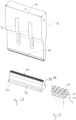
- Fig. 3A shows an isometric view of a combination of a sonotrode 1 and an anvil 20 according to a preferred embodiment of the invention.
- the sonotrode 1 comprises a series of slotted openings 70 to ensure a maximum vibration amplitude in the longitudinal length.
- the length of the sonotrode 71 is preferably equal to the length 72 of the sonotrode surface side 5.
- Fig. 3B shows a detailed view of the sonotrode in Fig. 3A , in which sonotrode welding contact elements 4 of a first row 11 of sonotrode welding contact elements that have a clear structure that differs from the sonotrode welding contact elements 4 of other rows.
- the sonotrode welding contact elements 4 of the first row 11 comprise a first adapted lateral surface 12, supplemented by, in particular, three lateral surfaces 10.
- Fig. 4A shows a cross-section of an anvil 20 according to a preferred embodiment of the present invention.
- the anvil 20 should be positioned on a suitable surface (not shown) that provides the necessary stability for the optimum functioning of the anvil during the ultrasonic welding.
- the anvil 20 according to a particular embodiment of the invention is optimised for ultrasonic welding of plastic, preferably a plastic container 2, and comprises an anvil surface 21 on which three rows of at least one anvil welding contact element 22 are positioned.
- the anvil welding contact elements also known as energy directors in the prior art, are positive protrusions provided so that during the ultrasonic welding of the plastic layers they are in contact with at least one part of the plastic layers.
- the anvil surface 21 is preferably rectangular or quadrangular, and comprises at least one anvil surface side 23.
- the anvil 20 has been specially developed to contribute to the forming of a weld seam on at least one part of the plastic to be welded.
- the anvil 20 is preferably made from aluminium, steel or titanium. Aluminium is more often used for low volume applications since an aluminium anvil 20 wears more quickly than titanium or steel.
- the material of the anvil 20 is not limited to the aforesaid materials, however.
- the anvil welding contact elements 22 can also be can specially hardened so that wear from usage is slower to occur.
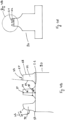
- FIG. 4B shows a detailed view of the cross-section of the anvil 20 in Fig. 4A .
- a first row 30 of anvil welding contact elements 22 differs from the other rows of anvil welding contact elements 22 in that aforesaid first row 30 of anvil welding contact elements 22 comprises a second adapted lateral surface 31, whereby the second adapted lateral surface 31 comprises a second substantially straight surface 29 and a second curved surface 32 that has a convex outward arch.
- Anvil welding contact elements 22 of the first row 30 are consequently defined by aforesaid second adapted lateral surface 31, and typically three second lateral surfaces 28, that are connected to at least one part of a second plateau surface 27.
- the second adapted lateral surface 31 is connected to at least one part of the second plateau surface 27, which defines an anvil welding contact element of the first row 30, and at least one part of the anvil surface side 23.
- the number of second lateral surfaces 28 is not limited to the aforesaid number of three.
- anvil welding contact elements 22 of the first row 30 reference is only being made to anvil welding contact elements 22 of the first row 30 that are provided so that during the ultrasonic welding they are in direct contact with the plastic to be welded, preferably a plastic container, more preferably a tube.
- Anvil welding contact elements 22 of the first row 30 that are not provided to be in direct contact with the plastic or plastic layers to be welded are not limited to aforesaid structure.
- the anvil welding contact elements 22 of the other rows, i.e. not first row 30, are defined by a second series of second lateral surfaces 28 and a second plateau surface 27. During the ultrasonic welding of a plastic the second plateau surface 27 of the anvil welding contact element 22 will make direct contact with at least one part of the plastic to be welded, preferably at least one part of the blow-moulded surface of a plastic container.
- second plateau surface 27 of the anvil welding contact elements 22 of the first row 30 is smaller than the second plateau surfaces 27 of the anvil welding contact elements 22 of the non-first row.
- the second plateau surface 27 of the anvil welding contact elements 22 of the non-first row is preferably rectangular with a surface of 0.80 mm ⁇ 0.88 mm, unlike the second plateau surface 27 of the anvil welding contact elements 22 of the first row 30 that preferably have a surface of 0.1 mm ⁇ 0.88 mm.
- the shape of the first second surfaces 27, and the dimensions are not limited to aforesaid form and dimensions.
- the surface of each second plateau surface 27 is smaller than 25 mm 2 , preferably smaller than 10 mm 2 , and more particularly smaller than 1 mm 2 .
- the second plateau surface 27 of an anvil welding contact element is positioned at a second height H2 34 in relation to the anvil surface 21.
- the second height H2 34 of an anvil welding contact element 22 is measured according to an imaginary perpendicular line on the anvil surface 21 through the midpoint of the second plateau surface 27 of aforesaid anvil welding contact element 22. This second height H2 34 is the same for all anvil welding contact elements 22 positioned on the same anvil surface 21.
- a difference in second height H2 34 between anvil welding contact elements 22 positioned on the same anvil surface 21 could lead to holes or openings in the plastic to be welded at points where the anvil welding contact elements 4 penetrate the plastic layers to be welded, or at points where the anvil welding contact elements 22 come into direct contact with at least one part of the anvil 1.
- the anvil welding contact elements 22 are also defined by a second width B2 35 that is measured as the smallest distance between two opposing second lateral surfaces 28 measured at a height of 30% of the second height H2 34 in relation to the anvil surface 21 on which the anvil welding contact elements 22 are positioned, and whereby at least one second width B2 35 is smaller than the second height H34.
- the second width B2 35 should be measured as the smallest diameter of the, preferably circular or elliptical, round form the circumference of which is defined by the second anvil surfaces 28 at a height of 30% of the second height H2 34 in relation to the anvil surface 21 on which the anvil welding contact elements 22 are positioned.
- the second height H2 34 is at least bigger than the second width B2 25, preferably at least bigger than twice aforesaid second width B2 35.
- the second height H2 34 should be a minimum of 1 mm, to allow the anvil welding contact element 22 to penetrate both the first plastic layer and the underlying plastic layer, preferably at least one part of the first wall of the plastic container 2 and at least one part of the top wall of the plastic container 2, whereby the wall is part of the blow-moulded surface of the plastic container 2.
- each aforesaid second substantially straight surface 29 makes an angle gamma 33 with the second plateau surface 27 with which it borders at least in part, whereby gamma 33 is situated in the range 75° to 90°, preferably between 82° and 88°.
- the second height H2 34 is at least bigger than aforesaid second width B2 35, preferably at least bigger than twice aforesaid second width B2 35. Consequently, taking into account aforesaid angle gamma 33 and the ratio of aforesaid second height H2 34 to aforesaid second width B2 35, the anvil welding contact elements are considered as positive protrusions.
- this is a top view of an anvil 20 according to a preferred embodiment of the invention. More particularly, this shows a top view of the anvil surface 21 on which the anvil welding contact elements 22 are positioned.
- the anvil surface 21 is preferably rectangular or quadrangular, and comprises at least one anvil surface side 23.
- the length 74 of the anvil surface side 23 is preferably equal to the length of the anvil 73.
- the geometry of the anvil surface 21 and aforesaid length 73 of the anvil are not limited to aforesaid geometry and length.
- the rows of anvil welding contact elements 22 are positioned according to aforesaid anvil surface side 23. Anvil welding contact elements 22 from the same row are positioned an equal distance away from aforesaid anvil surface side 23 and at the same distance from the opposing side of aforesaid anvil surface side 23.
- Fig. 5B shows a detailed view of the anvil surface structure in Fig. 5A , whereby the first row 30 of anvil welding contact elements 22 as described above is shown.
- the anvil 20 comprises three rows of anvil welding contact elements 22.
- a sufficient number of anvil welding contact elements 22 should be positioned on the anvil surface 21 for sufficient fusion of the plastic layers to be welded to be obtained.
- a pitch 69 is defined as centre-to-centre distance between two neighbouring welding contact elements 22, expressed in both the longitudinal direction of the anvil 20, i.e. according to the length 74 of the anvil surface side 23, and the transversal direction of the anvil, i.e. according to the width 76 of the anvil.
- a preferred embodiment of the anvil 20 according to the invention has a pitch of less than five times five (longitudinal direction ⁇ transversal direction) the largest diameter of the second plateau surface 27, more preferably less than three time three (longitudinal direction ⁇ transversal direction) the largest diameter of the second plateau surface 27.
- Aforesaid diameter is defined as the shortest distance between two opposing sides in the case of a polygonal structure, or as the diameter of the circle that defines the circular surface of the plateau surface 27.
- the pitch 69 should be selected such that at least in one direction, length and/or width, the minimum distance between two neighbouring anvil welding contact elements 22, measured parallel to the anvil surface 21, is greater than the first width B1 18 of the sonotrode welding contact elements 4 that is configured to be positioned between the two neighbouring anvil welding contact elements 22.
- Fig. 6A shows an isometric view of a combination of an anvil 20 and a sonotrode 1 according to a preferred embodiment of the invention.
- the elements defined for the sonotrode 1 are also shown in Fig. 3A and described above.
- the length of the anvil 73 is preferably equal to the length 74 of the anvil surface side 23.
- Fig. 6B shows a detailed view of the anvil 20 in Fig. 3A , in which anvil welding contact elements 22 of a first row 30 of anvil welding contact elements 22 have a clear structure that differs from the anvil welding contact elements 22 of other rows.
- the anvil welding contact elements 22 of the first row 30 comprise a second adapted lateral surface 31, supplemented by, in particular, three second lateral surfaces 28.
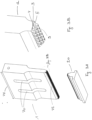
- Fig. 7 shows a combination of a sonotrode 1 and an anvil 20 according to a preferred embodiment of the invention.
- the sonotrode 1 and the anvil 20 have characteristics as described above.
- the sonotrode welding contact elements 4 align alternately with the anvil welding contact elements 22 whenever the sonotrode 1 and the anvil 20 are at a distance from each other that is smaller than the sum of the first height H1 17 and the second height H2 34.
- Alternate alignment means the alternating positioning of sonotrode 1 and anvil 20 welding contact elements 4, 22, such that the space between two neighbouring sonotrode welding contact elements 4 can be filled with an anvil welding contact element 22 whenever the sonotrode 1 and the anvil 20 move towards each other, whereby the welding contact surface between the plastic layers to be welded, increases preferably at least one part of the blow-moulded surface of a plastic container 2, and the welding contact elements 4, 22. In this way a stronger weld seam is obtained.
- the length 71 of the sonotrode 1 is at least bigger than the length 73 of the anvil 20.
- the length of the sonotrode in relation to the length of the anvil is not limited to the aforesaid ratio, however.
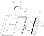
- Fig. 8 shows an isometric view of the combination in Fig. 7 , whereby at least one part of the plastic container 2 is positioned in the space between the sonotrode 1 and the anvil 20.
- the plastic container 2 comprises an open mouth 92 and a blow-moulded surface 91.
- the plastic container is obtained by a step of preform injection moulding in a plastic that can be extended biaxially, i.e. along two axes.
- This preform is preferably produced in polypropylene, but it can also be made from other polyolefins such as polyethylene or polyesters such as PET.
- the preforms can comprise two or more layers, whereby the layers comprise different plastics. These plastics can be selected to improve the barrier properties in respect of gas, moisture, light or chemicals. It is, furthermore, also possible to very quickly switch between colours or additives in the injection moulding process of the preform. These various preforms can then be blown identically.
- a second step the preform is blown in the manner of stretch blowing.
- the material is provided with a biaxial extension, which gives the material exceptional material properties in terms of strength and transparency.
- a particular element involves the inclusion in the blowing process of an advantageous way of embossing.
- a structure is hollowed out, preferably by means of etching, whereby the flat plate comprises an etchable material, preferably steel.
- the plates are applied in the blow mould. Recesses can be provided in the blow mould to allow these plates to drop onto the surface.
- the securing of the plates can take place by means of reversible adhesive systems or by means of magnets arranged in the blow mould.
- the stretch blowing method offers greater freedom in moulding. This allows various additional design elements to be added to the bottle.
- the blown plastic container 2 is cut to the desired length. This can preferably be performed using a guillotine system, possibly using laser cutting or possibly with contour cutting.
- the cutting step is not restricted to coming before the step of ultrasonic welding of the plastic container 2.
- the cutting step can be carried out during the ultrasonic welding of the plastic container 2. More particularly, the cutting step of the plastic container 2 can be carried out after the ultrasonic welding step.
- Fig. 9 shows the combination of a sonotrode 1 and an anvil 20, as in Fig. 8 .
- the sonotrode 1 and/or anvil 20 described are preferably used in a method for producing a plastic container 2, whereby at least one step of ultrasonic welding of the plastic container 2 for the forming of a weld seam 80 according a weld section 90 on at least one part of a blow-moulded surface 91 of the plastic container 2 in order to provide the plastic container 2 with at least one seal.
- at least one part of the weld seam 80 is produced by the sonotrode 1 or anvil 20 described, or a combination of the two.
- the step of ultrasonic welding comprises the following steps:
- the plastic container is produced according to a step of injection moulding of a biaxially extendable plastic container preform, whereby aforesaid plastic container preform comprises an open mouth and a sealed bottom. The open mouth is positioned opposite the sealed bottom. Furthermore, a step of stretch blowing of aforesaid biaxially extendable plastic container preform in a blow mould is applied, whereby the plastic container preform expands biaxially in the blow mould into aforesaid plastic container that is to be ultrasonically welded.
- the uncut bottle has a welded joint applied and is only cut in a subsequent step.
- This way of working has the major advantage that the trimming of the welded joint can be performed in one step with the cutting of the bottles.
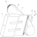
- Fig. 10 shows the step of clamping of the plastic container 2 between the sonotrode 1 and/or the anvil 20, preferably between the combination according to invention.
- the sonotrode 1 is operated for transferring mechanical energy via at least one part of the sonotrode welding contact elements 4, at least one part of the weld seam 80 can be obtained before sealing of the plastic container 2.
- the sonotrode 4 and anvil 22 welding contact elements come into direct contact with at least one part of the blow-moulded surface 91 of the plastic container 2.
- the weld section 90 can be determined at an arbitrary distance from the open mouth 92 of the plastic container 2.
- the first row of sonotrode welding contact elements 11 and the first row of anvil welding contact elements 30 should always be positioned at the edge of the opening mouth 92.
- Fig. 11A and Fig. 11B show a cross-section of the combination of the sonotrode 1 and the anvil 20 during clamping of the plastic container for the forming of a weld seam 80.
- the position of the first row of sonotrode welding contact elements 11 and the first row of anvil welding contact elements 30 in relation to the open mouth 92 of the plastic container 2 to be welded is clearly shown.
- Fig. 12A shows a front view of the combination in Fig. 10 .
- Fig. 12B shows a detailed view of the front view in Fig. 12A .
- the sonotrode welding contact elements 4 align alternately in relation to the anvil welding contact elements 22 whenever the sonotrode 1 and the anvil 20 are at a distance from each other that is smaller than the sum of the first height H1 17 and second height H2 34.
- Alternate alignment means the alternating positioning of sonotrode 1 and anvil 20 welding contact elements 4, 22, such that the space between two neighbouring sonotrode welding contact elements 4 can be filled with an anvil welding contact element 22 whenever the sonotrode 1 and the anvil 20 move towards each other, whereby the welding contact surface between the plastic layers to be welded, preferably at least one part of the blow-moulded surface of a plastic container 2, and the welding contact elements 4, 22, increases. In this way a stronger weld seam is obtained.
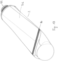
- Fig. 13 shows an isometric view of a plastic container 2 comprising a weld seam 80 obtained according to a preferred method of the invention comprising a step of ultrasonic welding, whereby the sonotrode 1 and the anvil 20 are used according to an embodiment of the invention.
- This plastic container 2 preferably a tube, still has to be cut according to a cutting line that can be defined between the weld seam 80 and the bottom of the plastic container 2, whereby the bottom is positioned opposite to the open mouth 92.
- Fig. 14 shows an isometric view of the combination in Fig. 10 , whereby a bottom of the plastic container is cropped.
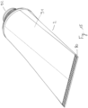
- Fig. 15 shows an isometric view of a plastic container 2, preferably a tube, obtained according to at least one of a preferred method for producing a plastic container according to the invention.
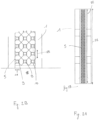
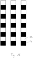
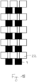
- Fig. 16 to Fig. 19 provide a schematic representation of a positioning, i.e. an alternating pattern, of the sonotrode welding contact elements 4, i.e. the black squares, in relation to the anvil welding contact elements 22, according to preferred embodiments of the invention, whereby the pitch has been adapted from figure to figure.
- the size and shape of the welding contact elements are the same in Fig. 16 to Fig. 19 for simplicity of the representation. However, the size and shape of the welding contact elements can differ as described above for the invention.
- Fig. 16 presents a schematic pattern of a preferred embodiment according to the invention and the pitch is the same in the longitudinal and transversal directions.
- the welding contact elements are alternately aligned such that the pitch should be greater than the width B1 18, B2 35, of the welding contact elements.
- Fig. 17 presents a schematic pattern of a preferred embodiment according to the invention and the pitch is the same in the longitudinal and in the transversal directions.
- the welding contact elements are alternately aligned such that the pitch should be greater than the width B1 18, B2 35, of the welding contact elements.
- the row of sonotrode welding contact elements 4 is shifted by one pitch in the transversal direction of the sonotrode 1 (or of the anvil 20).
- Fig. 18 presents a schematic pattern of a preferred embodiment according to the invention and the pitch in the longitudinal direction is greater than in the transversal direction of the sonotrode 1 (or of the anvil 20).
- Fig. 19 presents an alternating pattern of a preferred embodiment according to the invention and the pitch in the longitudinal direction is smaller than in the transversal direction of the sonotrode 1 (or of the anvil 20).
- Flexible plastic containers preferably tubes welded via the described method of ultrasonic welding, but without the deviating form of the first row of welding contact elements exhibit a clear improvement in the weld strength following the drop tests.
- the weld seam no longer breaks apart in full or in part, although splitting does occur where the weld seam joins the body of the tube.
- Flexible plastic containers preferably tubes, welded via the described method in which a convex curved surface is added to the first row of welding contact elements, exhibit no damage to the weld seam in drop tests.
- At least one of aforesaid preferred methods of the invention allows an empty plastic container, preferably a tube, to be produced which can be directly supplied to a filling machine.
- a tube can be produced with a relatively large drain opening.
- the drain opening can be made bigger than 10 mm, preferably even bigger than 15 mm, more particularly bigger than 20 mm. This allows the tube to be filled via the drain opening.
- the tube can either be supplied via a neck support, or the tube can be positioned in a holder that allows the tube to be positioned upright.
- Tubes produced via this method thus have a number of important advantages in terms of flexibility of production, decoration and filling.
Landscapes
- Engineering & Computer Science (AREA)
- Mechanical Engineering (AREA)
- Lining Or Joining Of Plastics Or The Like (AREA)
- Pressure Welding/Diffusion-Bonding (AREA)
Claims (18)
- Kombination aus einer Sonotrode (1) und einem Amboss (20), wobei die vorgenannte Sonotrode (1) zum Ultraschallschweißen eines Kunststoffbehälters (2) auf mindestens einem Teil einer blasgeformten Oberfläche des vorgenannten Kunststoffbehälters umfassta. eine, vorzugsweise rechteckige, Sonotrodenfläche (3) zur Positionierung von Sonotroden-Schweißkontaktelementen (4), wobei die vorgenannte Sonotrodenfläche (3) mindestens eine Sonotrodenflächenseite (5) umfasst,b. mindestens eine Reihe von mindestens einem Sonotroden-Schweißkontaktelement (4) das so vorgesehen ist dass es während des Schweißens in Kontakt mit dem Kunststoff steht, wobei das vorgenannte Sonotroden-Schweißkontaktelement (4) eine erste Plateaufläche (9) und eine erste Reihe von mindestens einer ersten Seitenfläche (10) umfasst, wobei die vorgenannte erste Seitenfläche (10) eine erste im Wesentlichen gerade Fläche (14) umfasst, wobei die vorgenannte mindestens eine Reihe von mindestens einem Sonotroden-Schweißkontaktelement (4) entsprechend der vorgenannten Sonotrodenflächenseite (5) positioniert ist,wobei die vorgenannte erste Reihe jedes der vorgenannten Sonotroden-Schweißkontaktelemente einer ersten Reihe (11) eine erste angepasste Seitenfläche (12) umfasst, die mindestens einen Teil der vorgenannten ersten Plateaufläche (9) mit mindestens einem Teil der vorgenannten Sonotrodenflächenseite (5) verbindet,und wobei der vorgenannte Amboss (20) zum Ultraschallschweißen des Kunststoffbehälters (2) umfasstc. eine, vorzugsweise rechteckige, Ambossfläche (21) zum Positionieren von Amboss-Schweißkontaktelementen (22), wobei die vorgenannte Ambossfläche (21) mindestens eine Ambossflächenseite (23) umfasst,d. mindestens eine Reihe von mindestens einem Amboss-Schweißkontaktelement (22) das so vorgesehen ist dass es während des Schweißens in Kontakt mit dem Kunststoff steht, wobei das vorgenannte Amboss-Schweißkontaktelement (22) eine zweite Plateaufläche (27) und eine zweite Reihe von mindestens einer zweiten Seitenfläche (28) umfasst, wobei die vorgenannte zweite Seitenfläche (28) eine zweite im Wesentlichen gerade Fläche (29) umfasst, wobei die vorgenannte mindestens eine Reihe von mindestens einem Amboss-Schweißkontaktelement (22) entsprechend der vorgenannten Ambossflächenseite (23) positioniert ist,wobei die vorgenannte erste vorgenannte zweite Reihe jedes vorgenannten Amboss-Schweißkontaktelements einer ersten Reihe (30) eine erste angepasste Seitenfläche (31) umfasst, die mindestens einen Teil der vorgenannten zweiten Plateaufläche (27) mit mindestens einem Teil der vorgenannten Ambossflächenseite (23) verbindet,wobeidas vorgenannte Sonotroden-Schweißkontaktelement (4) in Bezug auf das vorgenannte Amboss-Schweißkontaktelement (22) so positioniert ist, dass das vorgenannte Sonotroden-Schweißkontaktelement (4) beim Schweißen neben dem vorgenannten Amboss-Schweißkontaktelement (22) positioniert ist und zum Formen von jeweils mindestens einem Teil einer Schweißnaht (80) vorgesehen ist,dadurch gekennzeichnet, dass die vorgenannte erste angepasste Seitenfläche (12) des Sonotroden-Schweißkontaktelements (4) eine erste gekrümmte Fläche (13) umfasst, die zwischen der vorgenannten ersten Plateaufläche (9) und der vorgenannten ersten im Wesentlichen geraden Fläche (14) positioniert ist, wobei die vorgenannte erste gekrümmte Fläche (13) einen konvexen nach außen gerichteten Bogen aufweist,und dass die vorgenannte zweite angepasste Seitenfläche (31) des Amboss-Schweißkontaktelements (22) eine zweite gekrümmte Fläche (32) umfasst, die zwischen der vorgenannten zweiten Plateaufläche (27) und der vorgenannten zweiten im Wesentlichen geraden Fläche (29) positioniert ist, wobei die vorgenannte zweite gekrümmte Oberfläche (32) einen konvexen nach außen gerichteten Bogen aufweist.
- Kombination nach Anspruch 1, wobei die vorgenannte erste im Wesentlichen gerade Fläche (14) und die vorgenannte erste Plateaufläche (9) des vorgenannten Sonotroden-Schweißkontaktelements (4) einen Winkel Theta (15) definieren, wobei Theta (15) im Bereich von 75° bis 90°, vorzugsweise im Bereich von 82° bis 88° liegt.
- Kombination nach Anspruch 1 oder 2, wobei das vorgenannte Sonotroden-Schweißkontaktelement (4) eine erste Höhe H1 (17) und eine erste Breite B1 (18) definiert, wobei die vorgenannte erste Höhe H1 (17) zumindest größer als die vorgenannte erste Breite B1 (18), vorzugsweise mindestens größer als das Zweifache der vorgenannten ersten Breite B1 (18) ist.
- Kombination nach einem der vorstehenden Ansprüche, wobei die Größe der vorgenannten ersten Plateaufläche (9) des vorgenannten Sonotroden-Schweißkontaktelements (4) kleiner als 25 mm2, vorzugsweise kleiner als 10 mm2 und insbesondere kleiner als 1 mm2 ist.
- Kombination nach einem der vorstehenden Ansprüche, wobei die vorgenannte zweite im Wesentlichen gerade Fläche (29) und die vorgenannte zweite Plateaufläche (27) des vorgenannten Amboss-Schweißkontaktelements (22) einen Winkel Gamma (33) definieren, wobei Gamma (33) im Bereich von 75° bis 90°, vorzugsweise im Bereich von 82° bis 88° liegt.
- Kombination nach einem der vorstehenden Ansprüche, wobei das vorgenannte Amboss-Schweißkontaktelement (22) eine zweite Höhe H2 (34) und eine zweite Breite B2 (35) definiert, wobei die vorgenannte zweite Höhe H2 (34) zumindest größer als vorgenannte zweite Breite B2 (35), vorzugsweise zumindest größer als das Zweifache der vorgenannten zweiten Breite B2 (35) ist.
- Kombination nach einem der vorstehenden Ansprüche, wobei die Größe der vorgenannten zweiten Plateaufläche (27) des vorgenannten Amboss-Schweißkontaktelements (22) kleiner als 25 mm2, vorzugsweise kleiner als 10 mm2 und insbesondere kleiner als 1 mm2 ist.
- Kombination nach einem der vorstehenden Ansprüche, wobei die vorgenannte erste Reihe (11) von Ultraschallschweißkontaktelementen (4) direkt gegenüber der vorgenannten ersten Reihe (30) von Amboß-Schweißkontaktelementen (22) positioniert ist.
- Kombination nach einem der vorstehenden Ansprüche, wobei das Verhältnis der vorgenannten ersten Höhe H1 (17) zur vorgenannten ersten Breite B1 (18) das gleiche ist wie das Verhältnis der vorgenannten zweiten Höhe H2 (34) zur vorgenannten zweiten Breite B2 (35).
- Verfahren zum Herstellen eines Kunststoffbehälters (2), umfassend mindestens einen Schritt des Ultraschallschweißens des vorgenannten Kunststoffbehälters (2) zum Bilden der vorgenannten Schweißnaht (80) gemäß einem Schweißabschnitt (90) an mindestens einem Teil einer blasgeformten Oberfläche (91) des vorgenannten Kunststoffbehälters (2), um den vorgenannten Kunststoffbehälter mit mindestens einer Dichtung zu versehen,
dadurch gekennzeichnet, dass der vorgenannte Schritt des Ultraschallschweißens durch die Kombination nach einem der Ansprüche 1 bis 9 durchgeführt wird. - Verfahren zum Herstellen eines Kunststoffbehälters (2) nach Anspruch 10, wobei der vorgenannte Schritt des Ultraschallschweißens die folgenden Schritte umfasst:a. Bestimmen des vorgenannten Schweißabschnitts (90) auf der vorgenannten blasgeformten Oberfläche (91) des vorgenannten Kunststoffbehälters (2),b. Einspannen des vorgenannten Kunststoffbehälters (2) zwischen der vorgenannten Sonotrode (1) und/oder dem vorgenannten Amboss (20), vorzugsweise zwischen der Kombination, wobei die vorgenannten Schweißkontaktelemente (4, 22) mit mindestens einem Teil des vorgenannten Schweißabschnitts (90) verbunden sind,c. Bilden der vorgenannten Schweißnaht (80).
- Verfahren zum Herstellen eines Kunststoffbehälters nach Anspruch 10 oder 11, ferner umfassend die folgenden Schritte:a. Spritzgießen eines biaxial dehnbaren Kunststoffbehälter-Vorformlings, wobei der vorgenannte Kunststoffbehälter-Vorformling eine offene Öffnung (92) und einen abgedichteten Boden umfasst, wobei die vorgenannte offene Öffnung (92) gegenüber dem vorgenannten abgedichteten Boden positioniert ist,b. Streckblasen des vorgenannten biaxial dehnbaren Kunststoffbehälter-Vorformlings in einer Blasform, wobei der vorgenannte Kunststoffbehälter-Vorformling in der vorgenannten Blasform biaxial in den vorgenannten Kunststoffbehälter (2) expandiert, der die vorgenannte blasgeformte Oberfläche (91) umfasst, die zumindest teilweise mit ultraschallgeschweißt zu sein hat.
- Verfahren zu Herstellen eines Kunststoffbehälters (2) nach Anspruch 12, ferner umfassend einen Schritt des Prägens der vorgenannten blasgeformten Oberfläche während des vorgenannten Schritts des Streckblasens, wobei der vorgenannte Schritt des Prägens in der vorgenannten Blasform durchgeführt wird, die mindestens eine Platte, vorzugsweise eine geätzte Platte umfasst.
- Verfahren zum Herstellen eines Kunststoffbehälters nach einem der Ansprüche 10 bis 13, ferner umfassend einen Schritt des Schneidens des vorgenannten Kunststoffbehälters (2), wobei der vorgenannte Schritt des Schneidens vor, während oder nach dem Ultraschallschweißen des vorgenannten Kunststoffbehälters (2) durchgeführt wird.
- Verfahren zum Herstellen eines Kunststoffbehälters nach Anspruch 14, wobei der vorgenannte Schritt des Schneidens mechanisch oder mit Ultraschall durchgeführt wird.
- Kunststoffbehälter, vorzugsweise ein Rohr, der auf mindestens einem Teil einer blasgeformten Oberfläche des vorgenannten, nach einem der Ansprüche 10 bis 15 erhaltenen Kunststoffbehälters ultraschallgeschweißt ist.
- Verfahren zum Füllen eines Kunststoffbehälters (2) nach Anspruch 16, wobei das Füllen durch die vorgenannte offene Öffnung (92) erfolgt.
- Verwendung eines Kunststoffbehälters (2), der auf mindestens einem Teil einer blasgeformten Oberfläche des vorgenannten, nach einem der Ansprüche 10 bis 15 erhaltenen Kunststoffbehälters ultraschallgeschweißt ist, zum Verpacken von Pharmazeutika, Arzneimitteln, Kosmetika und Nahrungsmitteln.
Applications Claiming Priority (2)
| Application Number | Priority Date | Filing Date | Title |
|---|---|---|---|
| BE2016/5777A BE1024231B1 (nl) | 2016-10-18 | 2016-10-18 | Sonotrode en aambeeld voor het ultrasoon lassen van kunststoffen, werkwijze voor het produceren van een kunststofbehouder |
| PCT/IB2017/056466 WO2018073755A1 (en) | 2016-10-18 | 2017-10-18 | Sonotrode and anvil for ultrasonic welding of plastics, method for producing a plastic container |
Publications (2)
| Publication Number | Publication Date |
|---|---|
| EP3529052A1 EP3529052A1 (de) | 2019-08-28 |
| EP3529052B1 true EP3529052B1 (de) | 2023-06-07 |
Family
ID=57485263
Family Applications (1)
| Application Number | Title | Priority Date | Filing Date |
|---|---|---|---|
| EP17800608.6A Active EP3529052B1 (de) | 2016-10-18 | 2017-10-18 | Sonotrode und amboss zum ultraschallschweissen von kunststoffen, verfahren zur herstellung eines kunststoffbehälters |
Country Status (17)
| Country | Link |
|---|---|
| US (1) | US11155043B2 (de) |
| EP (1) | EP3529052B1 (de) |
| JP (1) | JP2019533591A (de) |
| KR (1) | KR20190071698A (de) |
| AU (1) | AU2017345501A1 (de) |
| BE (1) | BE1024231B1 (de) |
| BR (1) | BR112019007676A2 (de) |
| CA (1) | CA3040425A1 (de) |
| ES (1) | ES2951499T3 (de) |
| HU (1) | HUE063067T2 (de) |
| IL (1) | IL265966B2 (de) |
| MX (1) | MX2019004436A (de) |
| PL (1) | PL3529052T3 (de) |
| PT (1) | PT3529052T (de) |
| RU (1) | RU2750630C2 (de) |
| WO (1) | WO2018073755A1 (de) |
| ZA (1) | ZA201902430B (de) |
Cited By (1)
| Publication number | Priority date | Publication date | Assignee | Title |
|---|---|---|---|---|
| BE1032823A1 (nl) | 2024-07-31 | 2026-02-25 | Delta Eng | Werkwijze en inrichting voor het produceren van buizen uit blaasgevormde behouders |
Families Citing this family (10)
| Publication number | Priority date | Publication date | Assignee | Title |
|---|---|---|---|---|
| DE102017117078B4 (de) * | 2017-07-28 | 2019-06-13 | Schunk Sonosystems Gmbh | Sonotrode sowie Verfahren zur Beeinflussung des Schwingungsverhaltens einer Sonotrode |
| CN110142982B (zh) * | 2019-06-11 | 2024-04-05 | 常州聚豪电气有限公司 | 一种麦拉管智能分切生产线 |
| EP4017676A4 (de) * | 2019-09-26 | 2023-10-11 | Worldwide Machinery, Ltd | Trägermaterial zum schweissen |
| WO2022018948A1 (ja) * | 2020-07-20 | 2022-01-27 | トタニ技研工業株式会社 | 製袋方法、および、溶着方法 |
| KR102837947B1 (ko) * | 2020-10-22 | 2025-07-24 | 주식회사 엘지에너지솔루션 | 회전가능한 앤빌을 포함하는 초음파 용접 장치 및 이를 이용한 용접방법 |
| CN112848246B (zh) * | 2021-01-25 | 2023-02-03 | 宜宾天亿新材料科技有限公司 | 一种双轴取向塑料管的成型方法 |
| DE102021105265A1 (de) | 2021-03-04 | 2022-09-08 | Herrmann Ultraschalltechnik Gmbh & Co. Kg | Sonotrode mit beschichtetem Einlaufabschnitt |
| US12515413B2 (en) | 2021-04-14 | 2026-01-06 | Bayer Oy | Ultrasound thread welding |
| JP7397831B2 (ja) | 2021-08-06 | 2023-12-13 | プライムプラネットエナジー&ソリューションズ株式会社 | 超音波接合用ホーン |
| CN118660778A (zh) * | 2022-10-25 | 2024-09-17 | 宁德时代新能源科技股份有限公司 | 超声波焊接头和焊接设备 |
Citations (2)
| Publication number | Priority date | Publication date | Assignee | Title |
|---|---|---|---|---|
| WO1995029806A2 (en) * | 1994-04-29 | 1995-11-09 | Grant Chris J | Double orifice container |
| DE102010039003B4 (de) * | 2010-08-06 | 2014-01-16 | Telesonic Holding Ag | Vorrichtung zum Verschweißen und Prägen dünnwandiger Werkstücke mittels Ultraschall |
Family Cites Families (8)
| Publication number | Priority date | Publication date | Assignee | Title |
|---|---|---|---|---|
| US4767492A (en) * | 1986-04-18 | 1988-08-30 | Pola Chemical Industries, Inc. | Ultrasonic fuse-bonding sealing apparatus with improved contact surfaces |
| US5804008A (en) | 1994-08-31 | 1998-09-08 | E. I. Du Pont De Nemours And Company | Method and apparatus for making a tuftstring carpet |
| US5931324A (en) * | 1995-03-31 | 1999-08-03 | Graham Packaging Company, L.P. | Plastic container and non-integral handle |
| RU2394683C1 (ru) * | 2006-05-29 | 2010-07-20 | Тетра Лаваль Холдингз Энд Файнэнс Са | Герметизирующее устройство и способ производства герметичных упаковок для разливных пищевых продуктов |
| EP2113370B1 (de) * | 2008-04-29 | 2017-09-20 | Tetra Laval Holdings & Finance S.A. | Schweißbacke zur Herstellung versiegelter Packungen eines Lebensmittelproduktes |
| EP2368694A1 (de) * | 2010-03-22 | 2011-09-28 | Tetra Laval Holdings & Finance S.A. | Sonotrode |
| US9272802B2 (en) * | 2010-10-26 | 2016-03-01 | Rinco Ultrasonics USA, Inc. | Stepped sonotrode and anvil energy director grids for narrow/complex ultrasonic welds of improved durability |
| JP5899938B2 (ja) * | 2012-01-12 | 2016-04-06 | 日産自動車株式会社 | 二次電池の製造方法、二次電池 |
-
2016
- 2016-10-18 BE BE2016/5777A patent/BE1024231B1/nl active IP Right Grant
-
2017
- 2017-10-18 AU AU2017345501A patent/AU2017345501A1/en not_active Abandoned
- 2017-10-18 US US16/341,633 patent/US11155043B2/en active Active
- 2017-10-18 IL IL265966A patent/IL265966B2/en unknown
- 2017-10-18 BR BR112019007676A patent/BR112019007676A2/pt not_active Application Discontinuation
- 2017-10-18 MX MX2019004436A patent/MX2019004436A/es unknown
- 2017-10-18 RU RU2019111175A patent/RU2750630C2/ru active
- 2017-10-18 EP EP17800608.6A patent/EP3529052B1/de active Active
- 2017-10-18 WO PCT/IB2017/056466 patent/WO2018073755A1/en not_active Ceased
- 2017-10-18 PT PT178006086T patent/PT3529052T/pt unknown
- 2017-10-18 JP JP2019519705A patent/JP2019533591A/ja active Pending
- 2017-10-18 HU HUE17800608A patent/HUE063067T2/hu unknown
- 2017-10-18 PL PL17800608.6T patent/PL3529052T3/pl unknown
- 2017-10-18 KR KR1020197010532A patent/KR20190071698A/ko not_active Withdrawn
- 2017-10-18 ES ES17800608T patent/ES2951499T3/es active Active
- 2017-10-18 CA CA3040425A patent/CA3040425A1/en not_active Abandoned
-
2019
- 2019-04-16 ZA ZA2019/02430A patent/ZA201902430B/en unknown
Patent Citations (2)
| Publication number | Priority date | Publication date | Assignee | Title |
|---|---|---|---|---|
| WO1995029806A2 (en) * | 1994-04-29 | 1995-11-09 | Grant Chris J | Double orifice container |
| DE102010039003B4 (de) * | 2010-08-06 | 2014-01-16 | Telesonic Holding Ag | Vorrichtung zum Verschweißen und Prägen dünnwandiger Werkstücke mittels Ultraschall |
Cited By (2)
| Publication number | Priority date | Publication date | Assignee | Title |
|---|---|---|---|---|
| BE1032823A1 (nl) | 2024-07-31 | 2026-02-25 | Delta Eng | Werkwijze en inrichting voor het produceren van buizen uit blaasgevormde behouders |
| BE1032823B1 (nl) * | 2024-07-31 | 2026-03-05 | Delta Eng | Werkwijze en inrichting voor het produceren van buizen uit blaasgevormde behouders |
Also Published As
| Publication number | Publication date |
|---|---|
| RU2019111175A (ru) | 2020-11-20 |
| BR112019007676A2 (pt) | 2019-07-02 |
| HUE063067T2 (hu) | 2024-01-28 |
| IL265966B2 (en) | 2024-04-01 |
| US11155043B2 (en) | 2021-10-26 |
| CA3040425A1 (en) | 2018-04-26 |
| JP2019533591A (ja) | 2019-11-21 |
| US20190375166A1 (en) | 2019-12-12 |
| WO2018073755A1 (en) | 2018-04-26 |
| RU2750630C2 (ru) | 2021-06-30 |
| MX2019004436A (es) | 2019-06-12 |
| KR20190071698A (ko) | 2019-06-24 |
| AU2017345501A1 (en) | 2019-05-02 |
| IL265966B1 (en) | 2023-12-01 |
| ES2951499T3 (es) | 2023-10-23 |
| EP3529052A1 (de) | 2019-08-28 |
| PL3529052T3 (pl) | 2023-09-18 |
| IL265966A (en) | 2019-06-30 |
| RU2019111175A3 (de) | 2020-11-20 |
| PT3529052T (pt) | 2023-09-07 |
| BE1024231B1 (nl) | 2017-12-20 |
| ZA201902430B (en) | 2019-12-18 |
Similar Documents
| Publication | Publication Date | Title |
|---|---|---|
| US11155043B2 (en) | Sonotrode and anvil for ultrasonic welding of plastics, method for producing a plastic container | |
| EP0661208B1 (de) | Verfahren und Vorrichtung zur Herstellung eines Standbeutels mit einem Verschluss | |
| CA1079658A (en) | Stabilizing device for containers mainly intended for liquids under pressure | |
| US9272802B2 (en) | Stepped sonotrode and anvil energy director grids for narrow/complex ultrasonic welds of improved durability | |
| US10017287B2 (en) | Package formed with a stepped sonotrode/anvil combination having energy director grids for narrow ultrasonic welds of improved durability | |
| CN109689506B (zh) | 砧座以及超声波密封装置 | |
| AU2004299414B2 (en) | Arrangement and method for manufacturing PET bottle with handle formed at body part by injection blow molding, and PET bottle manufactured by them | |
| EP2447042A2 (de) | Sonotrode und Energiedirektorambossraster für enge/komplexe Ultraschallschweißnähte mit verbesserter Haltbarkeit | |
| KR20140067056A (ko) | 구조체의 제조 방법 및 상기 방법에 의해서 제조된 제품 | |
| US20130126524A1 (en) | Container | |
| US20080105587A1 (en) | Biodegradable blister package | |
| KR20070011169A (ko) | 용접 시임 및 호일 백을 형성하는 장치 및 방법 | |
| CA2238057C (en) | A method and an apparatus using ultrasound for fixedly welding a circular material blank | |
| JP2004196344A (ja) | インモールドラベル成形カップ及びその製造方法 | |
| JP2007301751A (ja) | プラスチックバッグの製造方法およびプラスチックバッグ | |
| CN120003048A (zh) | 连接工件的方法和复合制品 | |
| JP2007283660A (ja) | プラスチックバッグの製造方法 | |
| EP4375357A1 (de) | Verfahren zur herstellung eines zellkulturbehälters und zellkulturbehälter | |
| JP5226554B2 (ja) | 容器の充填口形成方法 | |
| EP4671151A1 (de) | Ausgiesser und verpackungsbehälter | |
| JP2007068830A (ja) | 輸液バッグ及びその製造方法 | |
| JP2013199293A (ja) | 蓋付容器、蓋付容器の製造方法および蓋付容器の製造装置 | |
| HK1196584B (en) | Method for producing a structure and product produced by the method | |
| SE510996C2 (sv) | Anordning för att medelst ultraljud fastsvetsa en materialrondell | |
| JP2010159073A (ja) | 容器のシール方法 |
Legal Events
| Date | Code | Title | Description |
|---|---|---|---|
| STAA | Information on the status of an ep patent application or granted ep patent |
Free format text: STATUS: UNKNOWN |
|
| STAA | Information on the status of an ep patent application or granted ep patent |
Free format text: STATUS: THE INTERNATIONAL PUBLICATION HAS BEEN MADE |
|
| PUAI | Public reference made under article 153(3) epc to a published international application that has entered the european phase |
Free format text: ORIGINAL CODE: 0009012 |
|
| STAA | Information on the status of an ep patent application or granted ep patent |
Free format text: STATUS: REQUEST FOR EXAMINATION WAS MADE |
|
| 17P | Request for examination filed |
Effective date: 20190513 |
|
| AK | Designated contracting states |
Kind code of ref document: A1 Designated state(s): AL AT BE BG CH CY CZ DE DK EE ES FI FR GB GR HR HU IE IS IT LI LT LU LV MC MK MT NL NO PL PT RO RS SE SI SK SM TR |
|
| AX | Request for extension of the european patent |
Extension state: BA ME |
|
| DAV | Request for validation of the european patent (deleted) | ||
| DAX | Request for extension of the european patent (deleted) | ||
| STAA | Information on the status of an ep patent application or granted ep patent |
Free format text: STATUS: EXAMINATION IS IN PROGRESS |
|
| 17Q | First examination report despatched |
Effective date: 20201125 |
|
| GRAP | Despatch of communication of intention to grant a patent |
Free format text: ORIGINAL CODE: EPIDOSNIGR1 |
|
| STAA | Information on the status of an ep patent application or granted ep patent |
Free format text: STATUS: GRANT OF PATENT IS INTENDED |
|
| INTG | Intention to grant announced |
Effective date: 20221130 |
|
| GRAS | Grant fee paid |
Free format text: ORIGINAL CODE: EPIDOSNIGR3 |
|
| GRAA | (expected) grant |
Free format text: ORIGINAL CODE: 0009210 |
|
| STAA | Information on the status of an ep patent application or granted ep patent |
Free format text: STATUS: THE PATENT HAS BEEN GRANTED |
|
| AK | Designated contracting states |
Kind code of ref document: B1 Designated state(s): AL AT BE BG CH CY CZ DE DK EE ES FI FR GB GR HR HU IE IS IT LI LT LU LV MC MK MT NL NO PL PT RO RS SE SI SK SM TR |
|
| REG | Reference to a national code |
Ref country code: GB Ref legal event code: FG4D |
|
| REG | Reference to a national code |
Ref country code: CH Ref legal event code: EP Ref country code: AT Ref legal event code: REF Ref document number: 1573766 Country of ref document: AT Kind code of ref document: T Effective date: 20230615 |
|
| REG | Reference to a national code |
Ref country code: DE Ref legal event code: R096 Ref document number: 602017069765 Country of ref document: DE |
|
| REG | Reference to a national code |
Ref country code: RO Ref legal event code: EPE |
|
| REG | Reference to a national code |
Ref country code: PT Ref legal event code: SC4A Ref document number: 3529052 Country of ref document: PT Date of ref document: 20230907 Kind code of ref document: T Free format text: AVAILABILITY OF NATIONAL TRANSLATION Effective date: 20230831 |
|
| REG | Reference to a national code |
Ref country code: NL Ref legal event code: FP |
|
| REG | Reference to a national code |
Ref country code: LT Ref legal event code: MG9D |
|
| REG | Reference to a national code |
Ref country code: ES Ref legal event code: FG2A Ref document number: 2951499 Country of ref document: ES Kind code of ref document: T3 Effective date: 20231023 |
|
| PG25 | Lapsed in a contracting state [announced via postgrant information from national office to epo] |
Ref country code: SE Free format text: LAPSE BECAUSE OF FAILURE TO SUBMIT A TRANSLATION OF THE DESCRIPTION OR TO PAY THE FEE WITHIN THE PRESCRIBED TIME-LIMIT Effective date: 20230607 Ref country code: NO Free format text: LAPSE BECAUSE OF FAILURE TO SUBMIT A TRANSLATION OF THE DESCRIPTION OR TO PAY THE FEE WITHIN THE PRESCRIBED TIME-LIMIT Effective date: 20230907 |
|
| REG | Reference to a national code |
Ref country code: GR Ref legal event code: EP Ref document number: 20230401440 Country of ref document: GR Effective date: 20231010 |
|
| PG25 | Lapsed in a contracting state [announced via postgrant information from national office to epo] |
Ref country code: RS Free format text: LAPSE BECAUSE OF FAILURE TO SUBMIT A TRANSLATION OF THE DESCRIPTION OR TO PAY THE FEE WITHIN THE PRESCRIBED TIME-LIMIT Effective date: 20230607 Ref country code: LV Free format text: LAPSE BECAUSE OF FAILURE TO SUBMIT A TRANSLATION OF THE DESCRIPTION OR TO PAY THE FEE WITHIN THE PRESCRIBED TIME-LIMIT Effective date: 20230607 Ref country code: LT Free format text: LAPSE BECAUSE OF FAILURE TO SUBMIT A TRANSLATION OF THE DESCRIPTION OR TO PAY THE FEE WITHIN THE PRESCRIBED TIME-LIMIT Effective date: 20230607 Ref country code: HR Free format text: LAPSE BECAUSE OF FAILURE TO SUBMIT A TRANSLATION OF THE DESCRIPTION OR TO PAY THE FEE WITHIN THE PRESCRIBED TIME-LIMIT Effective date: 20230607 |
|
| PG25 | Lapsed in a contracting state [announced via postgrant information from national office to epo] |
Ref country code: FI Free format text: LAPSE BECAUSE OF FAILURE TO SUBMIT A TRANSLATION OF THE DESCRIPTION OR TO PAY THE FEE WITHIN THE PRESCRIBED TIME-LIMIT Effective date: 20230607 |
|
| PG25 | Lapsed in a contracting state [announced via postgrant information from national office to epo] |
Ref country code: SK Free format text: LAPSE BECAUSE OF FAILURE TO SUBMIT A TRANSLATION OF THE DESCRIPTION OR TO PAY THE FEE WITHIN THE PRESCRIBED TIME-LIMIT Effective date: 20230607 |
|
| PG25 | Lapsed in a contracting state [announced via postgrant information from national office to epo] |
Ref country code: IS Free format text: LAPSE BECAUSE OF FAILURE TO SUBMIT A TRANSLATION OF THE DESCRIPTION OR TO PAY THE FEE WITHIN THE PRESCRIBED TIME-LIMIT Effective date: 20231007 |
|
| REG | Reference to a national code |
Ref country code: HU Ref legal event code: AG4A Ref document number: E063067 Country of ref document: HU |
|
| PG25 | Lapsed in a contracting state [announced via postgrant information from national office to epo] |
Ref country code: SM Free format text: LAPSE BECAUSE OF FAILURE TO SUBMIT A TRANSLATION OF THE DESCRIPTION OR TO PAY THE FEE WITHIN THE PRESCRIBED TIME-LIMIT Effective date: 20230607 Ref country code: SK Free format text: LAPSE BECAUSE OF FAILURE TO SUBMIT A TRANSLATION OF THE DESCRIPTION OR TO PAY THE FEE WITHIN THE PRESCRIBED TIME-LIMIT Effective date: 20230607 Ref country code: IS Free format text: LAPSE BECAUSE OF FAILURE TO SUBMIT A TRANSLATION OF THE DESCRIPTION OR TO PAY THE FEE WITHIN THE PRESCRIBED TIME-LIMIT Effective date: 20231007 Ref country code: EE Free format text: LAPSE BECAUSE OF FAILURE TO SUBMIT A TRANSLATION OF THE DESCRIPTION OR TO PAY THE FEE WITHIN THE PRESCRIBED TIME-LIMIT Effective date: 20230607 Ref country code: CZ Free format text: LAPSE BECAUSE OF FAILURE TO SUBMIT A TRANSLATION OF THE DESCRIPTION OR TO PAY THE FEE WITHIN THE PRESCRIBED TIME-LIMIT Effective date: 20230607 |
|
| REG | Reference to a national code |
Ref country code: DE Ref legal event code: R097 Ref document number: 602017069765 Country of ref document: DE |
|
| PLBE | No opposition filed within time limit |
Free format text: ORIGINAL CODE: 0009261 |
|
| STAA | Information on the status of an ep patent application or granted ep patent |
Free format text: STATUS: NO OPPOSITION FILED WITHIN TIME LIMIT |
|
| PG25 | Lapsed in a contracting state [announced via postgrant information from national office to epo] |
Ref country code: DK Free format text: LAPSE BECAUSE OF FAILURE TO SUBMIT A TRANSLATION OF THE DESCRIPTION OR TO PAY THE FEE WITHIN THE PRESCRIBED TIME-LIMIT Effective date: 20230607 |
|
| PG25 | Lapsed in a contracting state [announced via postgrant information from national office to epo] |
Ref country code: SI Free format text: LAPSE BECAUSE OF FAILURE TO SUBMIT A TRANSLATION OF THE DESCRIPTION OR TO PAY THE FEE WITHIN THE PRESCRIBED TIME-LIMIT Effective date: 20230607 |
|
| 26N | No opposition filed |
Effective date: 20240308 |
|
| PG25 | Lapsed in a contracting state [announced via postgrant information from national office to epo] |
Ref country code: SI Free format text: LAPSE BECAUSE OF FAILURE TO SUBMIT A TRANSLATION OF THE DESCRIPTION OR TO PAY THE FEE WITHIN THE PRESCRIBED TIME-LIMIT Effective date: 20230607 Ref country code: MC Free format text: LAPSE BECAUSE OF FAILURE TO SUBMIT A TRANSLATION OF THE DESCRIPTION OR TO PAY THE FEE WITHIN THE PRESCRIBED TIME-LIMIT Effective date: 20230607 |
|
| PG25 | Lapsed in a contracting state [announced via postgrant information from national office to epo] |
Ref country code: LU Free format text: LAPSE BECAUSE OF NON-PAYMENT OF DUE FEES Effective date: 20231018 |
|
| PG25 | Lapsed in a contracting state [announced via postgrant information from national office to epo] |
Ref country code: LU Free format text: LAPSE BECAUSE OF NON-PAYMENT OF DUE FEES Effective date: 20231018 |
|
| PG25 | Lapsed in a contracting state [announced via postgrant information from national office to epo] |
Ref country code: IE Free format text: LAPSE BECAUSE OF NON-PAYMENT OF DUE FEES Effective date: 20231018 |
|
| PG25 | Lapsed in a contracting state [announced via postgrant information from national office to epo] |
Ref country code: IE Free format text: LAPSE BECAUSE OF NON-PAYMENT OF DUE FEES Effective date: 20231018 |
|
| PG25 | Lapsed in a contracting state [announced via postgrant information from national office to epo] |
Ref country code: BG Free format text: LAPSE BECAUSE OF FAILURE TO SUBMIT A TRANSLATION OF THE DESCRIPTION OR TO PAY THE FEE WITHIN THE PRESCRIBED TIME-LIMIT Effective date: 20230607 |
|
| PG25 | Lapsed in a contracting state [announced via postgrant information from national office to epo] |
Ref country code: BG Free format text: LAPSE BECAUSE OF FAILURE TO SUBMIT A TRANSLATION OF THE DESCRIPTION OR TO PAY THE FEE WITHIN THE PRESCRIBED TIME-LIMIT Effective date: 20230607 |
|
| PG25 | Lapsed in a contracting state [announced via postgrant information from national office to epo] |
Ref country code: CY Free format text: LAPSE BECAUSE OF FAILURE TO SUBMIT A TRANSLATION OF THE DESCRIPTION OR TO PAY THE FEE WITHIN THE PRESCRIBED TIME-LIMIT; INVALID AB INITIO Effective date: 20171018 |
|
| REG | Reference to a national code |
Ref country code: AT Ref legal event code: UEP Ref document number: 1573766 Country of ref document: AT Kind code of ref document: T Effective date: 20230607 |
|
| REG | Reference to a national code |
Ref country code: CH Ref legal event code: U11 Free format text: ST27 STATUS EVENT CODE: U-0-0-U10-U11 (AS PROVIDED BY THE NATIONAL OFFICE) Effective date: 20251101 |
|
| PGFP | Annual fee paid to national office [announced via postgrant information from national office to epo] |
Ref country code: NL Payment date: 20251023 Year of fee payment: 9 |
|
| PGFP | Annual fee paid to national office [announced via postgrant information from national office to epo] |
Ref country code: PT Payment date: 20251105 Year of fee payment: 9 |
|
| PGFP | Annual fee paid to national office [announced via postgrant information from national office to epo] |
Ref country code: HU Payment date: 20251117 Year of fee payment: 9 |
|
| PGFP | Annual fee paid to national office [announced via postgrant information from national office to epo] |
Ref country code: DE Payment date: 20251020 Year of fee payment: 9 |
|
| PGFP | Annual fee paid to national office [announced via postgrant information from national office to epo] |
Ref country code: GB Payment date: 20251024 Year of fee payment: 9 |
|
| PGFP | Annual fee paid to national office [announced via postgrant information from national office to epo] |
Ref country code: AT Payment date: 20251021 Year of fee payment: 9 |
|
| PGFP | Annual fee paid to national office [announced via postgrant information from national office to epo] |
Ref country code: IT Payment date: 20251031 Year of fee payment: 9 |
|
| PGFP | Annual fee paid to national office [announced via postgrant information from national office to epo] |
Ref country code: FR Payment date: 20251024 Year of fee payment: 9 |
|
| PGFP | Annual fee paid to national office [announced via postgrant information from national office to epo] |
Ref country code: TR Payment date: 20251113 Year of fee payment: 9 Ref country code: BE Payment date: 20251022 Year of fee payment: 9 Ref country code: GR Payment date: 20251021 Year of fee payment: 9 |
|
| PGFP | Annual fee paid to national office [announced via postgrant information from national office to epo] |
Ref country code: CH Payment date: 20251101 Year of fee payment: 9 |
|
| PGFP | Annual fee paid to national office [announced via postgrant information from national office to epo] |
Ref country code: PL Payment date: 20251106 Year of fee payment: 9 |
|
| PGFP | Annual fee paid to national office [announced via postgrant information from national office to epo] |
Ref country code: RO Payment date: 20251113 Year of fee payment: 9 |
|
| PGFP | Annual fee paid to national office [announced via postgrant information from national office to epo] |
Ref country code: ES Payment date: 20251114 Year of fee payment: 9 |