EP3529149B1 - Multikopter mit angewinkelten rotoren - Google Patents
Multikopter mit angewinkelten rotoren Download PDFInfo
- Publication number
- EP3529149B1 EP3529149B1 EP17862880.6A EP17862880A EP3529149B1 EP 3529149 B1 EP3529149 B1 EP 3529149B1 EP 17862880 A EP17862880 A EP 17862880A EP 3529149 B1 EP3529149 B1 EP 3529149B1
- Authority
- EP
- European Patent Office
- Prior art keywords
- aircraft
- lift
- lift fans
- fans
- fuselage
- Prior art date
- Legal status (The legal status is an assumption and is not a legal conclusion. Google has not performed a legal analysis and makes no representation as to the accuracy of the status listed.)
- Active
Links
Images



Classifications
-
- G—PHYSICS
- G05—CONTROLLING; REGULATING
- G05D—SYSTEMS FOR CONTROLLING OR REGULATING NON-ELECTRIC VARIABLES
- G05D1/00—Control of position, course, altitude or attitude of land, water, air or space vehicles, e.g. using automatic pilots
- G05D1/08—Control of attitude, i.e. control of roll, pitch, or yaw
- G05D1/0808—Control of attitude, i.e. control of roll, pitch, or yaw specially adapted for aircraft
- G05D1/0858—Control of attitude, i.e. control of roll, pitch, or yaw specially adapted for aircraft specially adapted for vertical take-off of aircraft
-
- G—PHYSICS
- G05—CONTROLLING; REGULATING
- G05D—SYSTEMS FOR CONTROLLING OR REGULATING NON-ELECTRIC VARIABLES
- G05D1/00—Control of position, course, altitude or attitude of land, water, air or space vehicles, e.g. using automatic pilots
- G05D1/60—Intended control result
- G05D1/652—Take-off
-
- B—PERFORMING OPERATIONS; TRANSPORTING
- B64—AIRCRAFT; AVIATION; COSMONAUTICS
- B64C—AEROPLANES; HELICOPTERS
- B64C27/00—Rotorcraft; Rotors peculiar thereto
- B64C27/04—Helicopters
- B64C27/08—Helicopters with two or more rotors
-
- B—PERFORMING OPERATIONS; TRANSPORTING
- B64—AIRCRAFT; AVIATION; COSMONAUTICS
- B64C—AEROPLANES; HELICOPTERS
- B64C27/00—Rotorcraft; Rotors peculiar thereto
- B64C27/52—Tilting of rotor bodily relative to fuselage
-
- B—PERFORMING OPERATIONS; TRANSPORTING
- B64—AIRCRAFT; AVIATION; COSMONAUTICS
- B64C—AEROPLANES; HELICOPTERS
- B64C29/00—Aircraft capable of landing or taking-off vertically, e.g. vertical take-off and landing [VTOL] aircraft
- B64C29/0008—Aircraft capable of landing or taking-off vertically, e.g. vertical take-off and landing [VTOL] aircraft having its flight directional axis horizontal when grounded
- B64C29/0016—Aircraft capable of landing or taking-off vertically, e.g. vertical take-off and landing [VTOL] aircraft having its flight directional axis horizontal when grounded the lift during taking-off being created by free or ducted propellers or by blowers
- B64C29/0025—Aircraft capable of landing or taking-off vertically, e.g. vertical take-off and landing [VTOL] aircraft having its flight directional axis horizontal when grounded the lift during taking-off being created by free or ducted propellers or by blowers the propellers being fixed relative to the fuselage
-
- B—PERFORMING OPERATIONS; TRANSPORTING
- B64—AIRCRAFT; AVIATION; COSMONAUTICS
- B64D—EQUIPMENT FOR FITTING IN OR TO AIRCRAFT; FLIGHT SUITS; PARACHUTES; ARRANGEMENT OR MOUNTING OF POWER PLANTS OR PROPULSION TRANSMISSIONS IN AIRCRAFT
- B64D27/00—Arrangement or mounting of power plants in aircraft; Aircraft characterised by the type or position of power plants
- B64D27/02—Aircraft characterised by the type or position of power plants
- B64D27/30—Aircraft characterised by electric power plants
- B64D27/31—Aircraft characterised by electric power plants within, or attached to, wings
Definitions
- Multicopter aircraft typically include a plurality of horizontally oriented rotors, sometimes referred to as "lift fans,” to provide lift, stability, and control.
- a flight control system sometimes referred to as a “flight controller” or “flight computer” may be provided to translate pilot or other operator input, and/or corrections computed by an onboard computer, e.g., based on sensor data, into forces and moments and/or to further translate such forces and moments into a set of actuator (e.g., lift rotors; propellers; control surfaces, such as ailerons; etc.) and/or associated parameters (e.g., lift fan power, speed, or torque) to provide the required forces and moments.
- actuator e.g., lift rotors; propellers; control surfaces, such as ailerons; etc.
- associated parameters e.g., lift fan power, speed, or torque
- pilot or other operator inputs may indicate a desired change in the aircraft's speed, direction, and/or orientation, and/or wind or other forces may act on the aircraft, requiring the lift fans and/or other actuators to be used to maintain a desired aircraft attitude (roll/pitch/yaw), speed, and/or altitude.
- An aircraft typically is considered to have six degrees of freedom of movement, including forces in the forward/back, side/side, and up/down directions (e.g., Fx, Fy, and Fz) and moments about the longitudinal (roll) axis, the transverse (pitch) axis, and the vertical (yaw) axis (e.g., Mx, My, and Mz).
- forces in the forward/back, side/side, and up/down directions e.g., Fx, Fy, and Fz
- moments about the longitudinal (roll) axis, the transverse (pitch) axis, and the vertical (yaw) axis e.g., Mx, My, and Mz.
- Rotors may spin at a high rate and could pose a risk to an occupant of a manned multicopter and/or to equipment housed in a fuselage or other structure comprising the multicopter.
- US 3,089,666 describes fixed wing aircraft having power plants, the thrust directions of which relative to the aircraft fuselage can be changed so as to produce primarily a forward thrust to effect forward movement of the aircraft, or primarily a vertical thrust upward to facilitate rising of the aircraft during takeoff, or controlled descent during landing of the aircraft in a confined area.
- US 2003/094537 describes a vertical take-off and landing aircraft having a wing fitted with two nacelles one port and one starboard, each nacelle having two tiltmotors in tandem, one forward and one aft of the wing.
- Forward tiltmotors can be tilted up past the vertical and the aft pusher tiltmotors can be tilted down past the vertical so that the aircraft can maintain a steep descent with the propeller discs horizontal and a low angle of attack of the wing.
- Each engine is fitted with a two bladed variable pitch propeller that feathers to stop vertically.
- the tiltmotors have a sideways cant in the tilted positions to reduce engine side loads in translation.
- All the tiltmotors are equipped with emergency electric motors that can be used to shift the center of lift in hover and assist in gust control.
- a small wing is provided with very large flaps that are moved in synchronization with the tiltmotors to allow a clear downdraft and also act as a dive brake.
- a tricycle undercarriage has long nacelle legs to provide ground clearance for the aft propellers and is equipped with side-load sensors for weathercock control.
- An auto-pilot controls all phases of flight and has a manual back-up control system.
- US 2016/236775 describes a vertical takeoff and landing aircraft, which includes an airframe with a wing having an airfoil, the airfoil having an airfoil chord line and the wing having a wingspan.
- the aircraft further includes at least one forward thrust rotor having a horizontal thrust offset angle defined between the airfoil chord line and an axis of rotation of the forward thrust rotor.
- the aircraft further includes a plurality of vertical thrust rotors, each of the plurality of vertical thrust rotors having a vertical thrust offset angle defined between the airfoil chord line and a plane of rotation of the vertical thrust rotor.
- the vertical thrust offset angle is between 3 degrees and 10 degrees.
- the axis of rotation of the forward thrust rotor and planes of rotation of the plurality of vertical thrust rotors define a plurality of relative thrust angles that are each less than the horizontal thrust offset angle.
- EP 3 098 161 describes an aircraft comprising a support structure and at least four lift rotors. Each of the lift rotors is attached to the support structure and comprises at least one propeller. The lift rotors are constituted such that a rotational plane, in which the at least one propeller of the lift rotor rotates, is tilted with respect to a plane formed by the support structure.
- US 3,181,810 describes a system for controlling the flight attitude of a "VTOL aircraft", that is, aircraft which can take off and land vertically, and accomplish a transition between vertical and horizontal modes of flight.
- VTOL aircraft that is, aircraft which can take off and land vertically, and accomplish a transition between vertical and horizontal modes of flight.
- US20130220429A1 discloses an aircraft configured to provide safe operations while achieving robust control.
- an aircraft comprising: a fuselage; and a plurality of lift fans mounted on booms, each boom affixed to a corresponding wing of the aircraft, the plurality of lift fans including a first subset of lift fans disposed on a first side of the fuselage and a second subset of lift fans disposed on a second side of the fuselage, and wherein each lift fan is oriented at a corresponding angle ( ⁇ n) to a substantially horizontal plane of the aircraft, and the angle is of a non-zero magnitude such that a plane of rotation of the lift fan does not intersect the fuselage.
- FIG. 1 is a block diagram illustrating an embodiment of a flight control system.
- flight control system 100 includes a source of flight control inputs 102 configured to provide flight control inputs 104 to a controller 106, e.g., a flight control computer.
- source of inputs 102 may comprises one or both of pilot input, e.g., via manual flight controls, and auto-pilot or other self-piloting technologies.
- pilot inputs 104 may be generated by a self-piloting program/computer 102.
- source of inputs 102 may include manual input devices (sometimes referred to as "inceptors"), such as stick, throttle, rudder, collective, joystick, thumb stick, and/or other manual control/input devices configured to be manipulated by a pilot or other operator to control the flight of an aircraft.
- inceptors such as stick, throttle, rudder, collective, joystick, thumb stick, and/or other manual control/input devices configured to be manipulated by a pilot or other operator to control the flight of an aircraft.
- Such inceptor devices and/or associated electronics, and/or a self-piloting program, computer, or module may be configured to provide as input signals 104 one or more of a roll direction, roll rate, yaw direction, yaw rate, pitch angle, pitch rate, altitude, altitude rate and/or forward or other thrust input signal.
- controller 106 also receives sensor data 118, e.g., wind speed, air temperature, etc., from sensors 116.
- Flight controller 106 translates, aggregates, and/or otherwise processes and/or interprets the received flight control inputs 104 and/or sensor data 118 to generate and provide as output associated forces and/or moments 108 to be applied to the aircraft via its control assets (e.g., propellers, rotors, lift fans, aerodynamic control surfaces, etc.; sometimes referred to herein as "actuators”) to maneuver the aircraft in a manner determined based at least in part on the flight control inputs 104 and/or sensor data 118.
- control assets e.g., propellers, rotors, lift fans, aerodynamic control surfaces, etc.; sometimes referred to herein as "actuators”
- forces/moments 108 may include forces and/or moments along and/or about one or more axes of the aircraft, such as x, y, and z axes, corresponding to longitudinal, transverse, and vertical axes of the aircraft, respectively, in various embodiments.
- the flight control system 100 includes an online optimizer/mixer 110 configured to receive forces/moments 108.
- Online optimizer/mixer 110 receives as input forces/moments 108 and computes dynamically (online) a set of actuators and associated commands/parameters 112 to achieve the requested forces/moments 108. In some embodiments, the optimizer minimizes total power given a desired combination of forces and moments.
- Actuators 114 are configured to operate in response to actuator commands/parameters 112 provided by online optimizer/mixer 110.
- sensors 116 provide sensor data 118 to online optimizer/mixer 110.
- sensors 116 and/or sensor data 118 may include one or more of airspeed, temperature, or other environmental conditions; actuator availability, failure, and/or health information; aircraft attitude, altitude, and/or other position information; presence/absence of other aircraft, debris, or other obstacles in the vicinity of the aircraft; actuator position information; etc.
- online optimizer/mixer 110 may be configured to take sensor data 118 into account in determining an optimal mix of actuators and associated parameters to achieve a requested set of forces and moments.
- six or more lift fans may be provided to lift an aircraft into the air, enable the aircraft to hover, control aircraft attitude relative to the horizontal, etc.
- failure of a lift fan may be reflected in sensor data 118, resulting in a seamless response by online optimizer/mixer 110, which provides an optimal set of actuators and parameters 112 that omits (does not rely on) the failed lift fan.
- sensor data reflecting diminished power/performance, overheating, etc. may be taken into consideration, such as by adjusting a mapping of actuator parameter to expected effect on the aircraft for affected actuators.
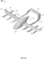
- FIG. 2A is a block diagram illustrating an embodiment of a multicopter aircraft with angled rotors.
- a flight control system such as flight control system 100 of Figure 1 may be embodied in an aircraft such as aircraft 200 of Figure 2A .
- aircraft 200 includes a fuselage (body) 202 and wings 204.
- a set of three underwing booms 206 is provided under each wing.
- Each boom 206 has two lift fans 208 mounted thereon, one forward of the wing and one aft.
- Each lift fan 208 may be driven by an associated drive mechanism, such as a dedicated electric motor.
- One or more batteries (not shown) and/or onboard power generators e.g., small gas turbine
- each boom 206 is positioned at an angle relative to a vertical axis of the aircraft such that the lift fans 208 are mounted thereon at an associated angle, as described more fully in connection with Figures 2B - 2E .
- a propeller 210 is mounted on the fuselage 202 and configured to push the aircraft through the air in the forward (e.g., x axis) direction.
- the propeller 210 is positioned between a pair of tail booms 212 that extend aft and are joined at their aft end by a tail structure on which aerodynamic control surfaces including elevators 216 and rudder 218 are mounted.
- each of the inboard booms 206 forms at least in part an integral part of the corresponding port/starboard side tail boom 212.
- the tail booms 212 comprise extensions aft from the respective inboard booms 206.
- tail booms 212 may be formed as part of or fastened (e.g., bolted) to an aft end of the corresponding inboard boom 206.
- Additional control surfaces include ailerons 214 mounted on the trailing edge of wings 204.
- ailerons 214 are included, e.g., to provide redundancy. In some embodiments, if a single aileron 214 is lost or fails the remaining three ailerons 214 are sufficient to control the aircraft. Likewise, in some embodiments, loss of one rudder 218 results in one remaining rudder to provide a degree of yaw control, along with the lift fans. Finally, in some embodiments four elevators 216 are provided for loss/failure tolerance.
- an aircraft 200 as shown in Figure 2A may have the following approximate dimensions: • Wingspan: 36.0 feet (10.97 m) • Nose to tail: 21.4 feet (6.52 m) • Centerline to first boom: 6.1 feet (1.86 m) • Distance between inner booms: 12.2 feet (3.72 m) • Spacing between booms (same wing): 4.0 feet (1.22 m) • Push propeller sweep: 6.5 feet (1.98 m) • Lift fan sweep: 4.2 feet (1.28 m) • Distance between fan centers (same boom) 8.7 feet (2.65m)
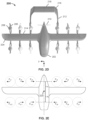
- Figure 2B is a block diagram showing a front view of the multicopter aircraft 200 of Figure 2A . Coordinate axes in the z (vertical) and y (side) direction are indicated.
- the front view shown in Figure 2B illustrates the respective angles off the vertical axis (z axis as labeled), sometimes referred to herein as "cant angles", at which the outboard, middle, and inboard pairs of lift fans 206 are oriented.
- angling the lift fans may provide additional options to control the aircraft, especially at or near hover.
- different combinations of fans may be used to exercise yaw control (e.g., rotate around z axis), to slip sideways or counteract the force of wind while in a hover (y axis), etc.
- the respective angles at which lift fans 208 may be oriented may be determined based at least in part on safety considerations, such as to increase the likelihood that debris thrown centrifugally from a lift fan, e.g., should the lift fan break apart, would be propelled on a trajectory and/or in a plane that does not intersect a human- occupied portion of fuselage 202.
- safety considerations such as to increase the likelihood that debris thrown centrifugally from a lift fan, e.g., should the lift fan break apart, would be propelled on a trajectory and/or in a plane that does not intersect a human- occupied portion of fuselage 202.
- two side by side seats are provided for passengers in a forward part of fuselage 202.
- Batteries to power the lift fans 208 and/or push propeller 210 may be located in a central/over wing part of the fuselage 202, and in some embodiments both the human-occupied and battery occupied parts of the fuselage are protected at least in part by canting the booms/lift fans as disclosed herein.
- lift fan cant angles may be determined at least in part via a constrained optimization design process.
- the fan cants e.g., roll and pitch fan angles
- the fan cants may be determined by an optimization process in which an object is to minimize the amount of torque required by any individual motor for a variety of trimmed or equilibrium conditions including: angular accelerations, any individual fan failure, crosswinds, and center of gravity variations.
- the optimization is subject to constraints of preventing the plane of the fan blade from intersecting the crew in the event of catastrophic failure of a fan.
- Another example of a constraint that may be applied is ensuring that the fans are aligned to the local flow angle for forward flight with the fans stopped and aligned with the boom.
- the effective forces and moments capable of being provided by each respective lift fan may be stored onboard the aircraft 200 in a memory or other data storage device associated with the onboard flight control system.
- a matrix, table, database, or other data structure may be used.
- effectiveness under different operating conditions may be stored. For example, effectiveness of a lift fan or control surface may be different depending on conditions such as airspeed, temperature, etc.
- forces and moments expected to be generated by a lift fan or other actuator under given conditions may be discounted or otherwise reduced, e.g., by a factor determined based at least in part on an environmental or other variable, such as a measure of lift fan motor health.
- the forces and moments capable of being generated by a given lift fan may reflect the angle at which each lift fan is mounted.
- lift fans mounted at an angle relative to the horizontal plane of the aircraft would generate a horizontal force component and a vertical force component, and each force may generate a corresponding moment about one or more axes of the aircraft, depending on the location at which the fan is mounted relative to the center of gravity of the aircraft.
- FIG. 2C is a block diagram illustrating an example of angled rotors as implemented in an embodiment of a multicopter aircraft with angled rotors.
- the approximate angles at which the left side (as viewed from the front) rotors of the aircraft 200 as shown in Figures 2A and 2B are mounted are shown.
- the left most (outboard) lift fan is shown to be mounted at an angle O1 to the vertical (and, therefore, horizontal/lateral) axis of the aircraft, tilting away from fuselage 202, resulting in a plane of rotation of the lift fan, indicated by the dashed arrow extending away from the lift fan, not intersecting the fuselage 202.
- the plane of rotation may intersect the fuselage but not a human-occupied or otherwise critical portion thereof.
- the middle lift fan and the inboard lift fan have been angled in towards the fuselage 202, resulting in their respective planes of rotation being rotated downward by corresponding angles, such that they do not intersect the fuselage 202.
- angling lift fans or other rotors towards or away from a fuselage and preferably critical portions thereof, and/or preferably other critical structures may decrease the risk that debris thrown centrifugally from the rotor would hit the fuselage and preferably other structure.
- FIG. 2D is a block diagram illustrating a top view of an embodiment of a multicopter aircraft with angled rotors.
- a top view off aircraft 200 of Figure 2A is shown. Coordinate axes in the x (forward) and y (side) direction are indicated.
- the aircraft 200 includes twelve lift fans 208, six on either side of the fuselage 202. On each side of the fuselage 202, three lift fans are mounted forward of the wing 204 and three aft. The lift fans 208 are mounted in pairs on corresponding booms 206 mounted under the wings 204. The outermost booms are tilted away from the fuselage 202 and the middle and inner booms are tilted towards the fuselage, as shown in Figures 2B and 2C .
- Figure 2E is a block diagram illustrating an example of forces and moments capable of being generated by angled rotors in an embodiment of a multicopter aircraft with angled rotors.
- the fuselage 202 of the aircraft 200 of Figure 2D is shown to have a center of gravity 220.
- the circles in Figure 2E each represent a corresponding one of the lift fans 208.
- the arrows labeled F y1 , F y2 , etc. represent the respective lateral (y-axis) components of the force generated by the angled lift fans 208 by virtue of their being mounted at angles, and shown in Figures 2A - 2D .
- the rear (aft) fans are shown to be mounted at an x-axis distance x 1 from center of gravity 220.
- the y-axis components of the rear lift fans would result in corresponding moments of magnitudes proportional to the distance x1 being applied to the aircraft about the vertical axis (z-axis, using the convention shown in Figures 2A - 2E ).
- the moment contributed by any given one of the rear lift fans would be determined by the lift force generated by the lift fan as actuated by the flight control system, with the direction (counter-clockwise or clockwise) depending on the position of the lift fan and whether it was tilted away from or towards the fuselage 202.
- the rear leftmost lift fan would contribute a lateral force F y1 resulting in contributing a counter-clockwise moment component about the center of gravity 220.
- the lift fans associated with lateral force components F y2 , F y3 , and F y6 would contribute clockwise moment components.
- the forward lift fans (associated with lateral force components F y7 - F y12 , in this example) would contribute moment components proportional to the x-axis distance x 2 at which they are mounted relative to the center of gravity 220.
- the respective lift fans 208 may be rotated in alternating clockwise or counterclockwise rotations, e.g., to balance side forces associated with rotation direction.
- a total of twelve lift fans 208 are included.
- an even number of lift fans including at least four lift fans may be included and distributed evenly on each side of the fuselage. Upon loss or failure of a lift fan, a corresponding lift fan on an opposite side of the aircraft may be deactivated, to maintain balance.
- loss of a clockwise rotating lift fan on a forward end of an innermost boom on a port side of the aircraft may result in a counterclockwise rotating lift fan in a complementary position on the opposite side, such as the aft end of the innermost boom on the opposite side, may be shut down and omitted from use (e.g., zero RPM/torque added as a constraint for that lift fan) in subsequent optimization computations to determine mixes of actuators and associated parameters to achieve desired forces and moments.
- Figure 2F is a block diagram showing a side view of the multicopter aircraft 200 of Figure 2A .
- the lift fans 208 are mounted at a prescribed forward tilt relative to a horizontal plane of the aircraft 200.
- the booms 206 are shown to be mounted substantially aligned with the horizontal plane of the aircraft 200 when in level flight.
- the wings 204 sweep up slightly as they extend away from the fuselage 202.
- the angle at which the lift fans 208 are tilted forward may be determined at least in part on the same considerations as the angles illustrated in Figures 2B and 2C , i.e., to ensure that debris thrown centrifugally from a lift fan if it were to break apart would not intersect at least a human-occupied or otherwise critical portion of a cockpit or cabin portion of fuselage 202.
- the angle at which the lift fans 208 are tilted forward may be selected at least in part to minimize drag, turbulence, or other undesirable aerodynamic effects of the lift fans when the aircraft 200 is in forward flight, e.g., being propelled by push propeller 210.
- Figure 2G is a block diagram showing a side view of the multicopter aircraft 200 of Figure 2A .
- approximate airflow patterns are illustrated by arrows 242 and 244.
- Arrow 242 shows air flowing with minimal resistance over the forward lift fans 208 and, due in part to the forward tilt of the forward lift fans 242, continuing relatively unimpeded over wing 204, and clearing the aft lift fans 208 (or, in some embodiments, flowing over them in a relatively low drag path, due in part to their forward tilt).
- Arrow 244 shows air flowing under/through the forward lift fans 208, under the wing 204, and flowing over the aft lift fans 208 in a relatively low drag manner, due at least in part to the forward tilt of the aft lift fans 208.
- the wing 204 may not sweep upward to the same extent as shown in Figures 2F and 2G , and in some such embodiments the aft lift fans may be more within a same horizontal plane as the forward lift fans 208 and wing 204. In some such embodiments, the aft lift fans 208 may be tilted back slightly, instead of forward, to provide a continuous, relatively low drag pathway for air to flow over the forward lift fans 208, the wing 204, and the after lift fans 208, e.g., when the aircraft 200 is in forward flight mode.
- a flight control system such as flight control system 100 of Figure 1 , is configured to determine a mix of actuators and corresponding actuator parameters, including of lift fans 208, to achieve required forces and moments, including by taking into consideration the moments about the z-axis that would be generated and applied to the aircraft 200 by virtue of the lift fans being mounted at angles, as disclosed herein.
Landscapes
- Engineering & Computer Science (AREA)
- Aviation & Aerospace Engineering (AREA)
- Mechanical Engineering (AREA)
- Automation & Control Theory (AREA)
- Physics & Mathematics (AREA)
- General Physics & Mathematics (AREA)
- Remote Sensing (AREA)
- Radar, Positioning & Navigation (AREA)
- Aerodynamic Tests, Hydrodynamic Tests, Wind Tunnels, And Water Tanks (AREA)
- Structures Of Non-Positive Displacement Pumps (AREA)
- Turbine Rotor Nozzle Sealing (AREA)
- Control Of Position, Course, Altitude, Or Attitude Of Moving Bodies (AREA)
- Confectionery (AREA)
Claims (8)
- Flugzeug (200), das Folgendes umfasst:einen Rumpf (202) undmehrere Hubgebläse (208), die an Ausleger (206) angebracht sind, wobei jeder Ausleger an einem entsprechenden Flügel (204) des Flugzeugs befestigt ist, wobei zu den mehreren Hubgebläsen ein erster Teilsatz Hubgebläse, die auf einer ersten Seite des Rumpfes angeordnet sind, und ein zweiter Teilsatz Hubgebläse gehört, die auf einer zweiten Seite des Rumpfes angeordnet sind, und wobei jedes Hubgebläse in einem entsprechenden Winkel (θn) zu einer im Wesentlichen horizontalen Ebene des Flugzeugs ausgerichtet ist und der Winkel nicht null beträgt, so dass eine Rotationsebene des Hubgebläses den Rumpf nicht schneidet.
- Flugzeug (200) nach Anspruch 1, wobei jedes Hubgebläse (208) zumindest teilweise durch Anbringen eines entsprechenden Auslegers (206) in dem entsprechenden Winkel (θn) in dem entsprechenden Winkel ausgerichtet ist.
- Flugzeug (200) nach Anspruch 1, wobei zu einem vorderen Teilsatz ein oder mehrere der mehreren Hubgebläse (208) gehören, die vor einem Schwerpunkt des Flugzeugs angebracht sind, und zu einem hinteren Teilsatz ein oder mehrere der mehreren Hubgebläse gehören, die hinter dem Schwerpunkt angebracht sind.
- Flugzeug (200) nach Anspruch 3, wobei sowohl zu dem vorderen als auch zu dem hinteren Teilsatz eine erste Gruppe Hubgebläse (208), die in Bezug auf die Vertikale in einer ersten Richtung abgewinkelt sind, und eine zweite Gruppe Hubgebläse gehört, die in Bezug auf die Vertikale in einer der ersten Richtung entgegengesetzten zweiten Richtung abgewinkelt sind.
- Flugzeug (200) nach Anspruch 1, wobei sich durch eine Ausrichtung der Hubgebläse (208) in jeweiligen Winkeln (θn) eine Querkraftkomponente (Fyn) der von den Hubgebläsen erzeugten jeweiligen Hubkräfte ergibt, mit denen das Flugzeug baufschlagt wird.
- Flugzeug (200) nach Anspruch 5, das ferner ein Flugsteuerungssystem (100) umfasst, welches einen Prozessor (106) aufweist, der so konfiguriert ist, dass er die Querkraftkomponenten (Fyn) zum Steuern des Gierens um eine im Wesentlichen vertikale Gierachse des Flugzeugs benutzt.
- Flugzeug (200) nach Anspruch 5, das ferner ein Flugsteuerungssystem (100) umfasst, welches einen Prozessor (106) aufweist, der so konfiguriert ist, dass er einen Satz Aktoren (114) und zugehöriger Aktorparameter bestimmt und so das Flugzeug mit einem angeforderten Satz Kräfte und Momente beaufschlagt wird, wobei zu dem angeforderten Satz Kräfte und Momente ein Moment um eine im Wesentlichen vertikale Gierachse des Flugzeugs gehört, und wobei der Prozessor so konfiguriert ist, dass er beim Bestimmen des Satzes Aktoren und zugehöriger Aktorparameter die von den Hubgebläsen (208) erzeugten Querkraftkomponenten (Fyn), mit denen das Flugzeug beaufschlagt wird, und den jeweiligen Beitrag der Querkraftkomponenten zu einem Nettomoment um die im Wesentlichen vertikale Gierachse des Flugzeugs berücksichtigt.
- Flugzeug (200) nach Anspruch 1, wobei die mehreren Hubgebläse (208) in Bezug auf die horizontale Ebene des Flugzeugs (200) nach vom geneigt angebracht sind.
Priority Applications (3)
| Application Number | Priority Date | Filing Date | Title |
|---|---|---|---|
| EP25207340.8A EP4653972A3 (de) | 2016-10-18 | 2017-10-16 | Multikopter mit abgewinkelten rotoren |
| EP25207347.3A EP4653973A3 (de) | 2016-10-18 | 2017-10-16 | Multikopter mit abgewinkelten rotoren |
| EP23216810.4A EP4318167B1 (de) | 2016-10-18 | 2017-10-16 | Multikopter mit abgewinkelten rotoren |
Applications Claiming Priority (2)
| Application Number | Priority Date | Filing Date | Title |
|---|---|---|---|
| US15/297,030 US10364024B2 (en) | 2016-10-18 | 2016-10-18 | Multicopter with angled rotors |
| PCT/US2017/056817 WO2018075412A1 (en) | 2016-10-18 | 2017-10-16 | Multicopter with angled rotors |
Related Child Applications (4)
| Application Number | Title | Priority Date | Filing Date |
|---|---|---|---|
| EP23216810.4A Division-Into EP4318167B1 (de) | 2016-10-18 | 2017-10-16 | Multikopter mit abgewinkelten rotoren |
| EP23216810.4A Division EP4318167B1 (de) | 2016-10-18 | 2017-10-16 | Multikopter mit abgewinkelten rotoren |
| EP25207347.3A Division EP4653973A3 (de) | 2016-10-18 | 2017-10-16 | Multikopter mit abgewinkelten rotoren |
| EP25207340.8A Division EP4653972A3 (de) | 2016-10-18 | 2017-10-16 | Multikopter mit abgewinkelten rotoren |
Publications (3)
| Publication Number | Publication Date |
|---|---|
| EP3529149A1 EP3529149A1 (de) | 2019-08-28 |
| EP3529149A4 EP3529149A4 (de) | 2020-06-17 |
| EP3529149B1 true EP3529149B1 (de) | 2024-07-24 |
Family
ID=61902127
Family Applications (4)
| Application Number | Title | Priority Date | Filing Date |
|---|---|---|---|
| EP25207347.3A Pending EP4653973A3 (de) | 2016-10-18 | 2017-10-16 | Multikopter mit abgewinkelten rotoren |
| EP23216810.4A Active EP4318167B1 (de) | 2016-10-18 | 2017-10-16 | Multikopter mit abgewinkelten rotoren |
| EP25207340.8A Pending EP4653972A3 (de) | 2016-10-18 | 2017-10-16 | Multikopter mit abgewinkelten rotoren |
| EP17862880.6A Active EP3529149B1 (de) | 2016-10-18 | 2017-10-16 | Multikopter mit angewinkelten rotoren |
Family Applications Before (3)
| Application Number | Title | Priority Date | Filing Date |
|---|---|---|---|
| EP25207347.3A Pending EP4653973A3 (de) | 2016-10-18 | 2017-10-16 | Multikopter mit abgewinkelten rotoren |
| EP23216810.4A Active EP4318167B1 (de) | 2016-10-18 | 2017-10-16 | Multikopter mit abgewinkelten rotoren |
| EP25207340.8A Pending EP4653972A3 (de) | 2016-10-18 | 2017-10-16 | Multikopter mit abgewinkelten rotoren |
Country Status (6)
| Country | Link |
|---|---|
| US (5) | US10364024B2 (de) |
| EP (4) | EP4653973A3 (de) |
| CN (2) | CN114872890A (de) |
| AU (4) | AU2017346502B2 (de) |
| NZ (1) | NZ752614A (de) |
| WO (1) | WO2018075412A1 (de) |
Families Citing this family (45)
| Publication number | Priority date | Publication date | Assignee | Title |
|---|---|---|---|---|
| TWI538852B (zh) | 2011-07-19 | 2016-06-21 | 季航空股份有限公司 | 個人飛機 |
| US9694911B2 (en) * | 2014-03-18 | 2017-07-04 | Joby Aviation, Inc. | Aerodynamically efficient lightweight vertical take-off and landing aircraft with pivoting rotors and stowing rotor blades |
| US10364024B2 (en) | 2016-10-18 | 2019-07-30 | Kitty Corporation | Multicopter with angled rotors |
| US10364036B2 (en) | 2016-10-18 | 2019-07-30 | Kitty Hawk Corporation | Multicopter with boom-mounted rotors |
| CN116714761B (zh) * | 2016-11-02 | 2026-04-24 | 杰欧比航空有限公司 | 使用旋翼以模拟刚性机翼空气动力学的vtol飞行器 |
| US10526079B1 (en) | 2017-07-13 | 2020-01-07 | Kitty Hawk Corporation | Multicopter with wide span rotor configuration and protective fuselage |
| US10822101B2 (en) * | 2017-07-21 | 2020-11-03 | General Electric Company | Vertical takeoff and landing aircraft having a forward thrust propulsor |
| US10745099B2 (en) * | 2017-08-31 | 2020-08-18 | Wisk Aero Llc | Conductor in composite |
| US20210001979A1 (en) * | 2017-11-02 | 2021-01-07 | Joby Aero, Inc. | Vtol aircraft using fixed forward canted rotors to simulate rigid wing dynamics |
| WO2019090191A1 (en) | 2017-11-03 | 2019-05-09 | Uber Technologies, Inc. | Vtol m-wing configuration |
| US11136115B2 (en) * | 2018-06-20 | 2021-10-05 | Textron Innovations Inc. | Tilted propellers for enhanced distributed propulsion control authority |
| US11027836B2 (en) * | 2018-07-13 | 2021-06-08 | The Boeing Company | Rotorcraft with canted coaxial rotors |
| US11440671B2 (en) * | 2019-01-24 | 2022-09-13 | Amazon Technologies, Inc. | Adjustable motor fairings for aerial vehicles |
| US11453489B2 (en) * | 2019-02-20 | 2022-09-27 | Shanghai Autoflight Co., Ltd. | Vertical takeoff and landing aerial vehicle |
| EP3702277B1 (de) * | 2019-02-27 | 2021-01-27 | AIRBUS HELICOPTERS DEUTSCHLAND GmbH | Für senkrechtstart und -landung (vtol) geeignetes mehrrotorflugzeug |
| EP3730404B1 (de) | 2019-04-23 | 2021-08-18 | LEONARDO S.p.A. | Flugzeug mit senkrechtstart und -landung und kontrollmethode |
| US11829161B2 (en) | 2019-04-26 | 2023-11-28 | Aergility Corporation | Hybrid gyrodyne aircraft |
| US11643199B2 (en) * | 2019-05-10 | 2023-05-09 | Eve Uam, Llc | Vertical take-off and landing (VTOL) aircraft |
| US11597505B1 (en) * | 2019-05-31 | 2023-03-07 | Sifly Aviation, Inc. | Rotorcraft optimized for forward flight |
| CN110525643A (zh) * | 2019-09-18 | 2019-12-03 | 深圳飞马机器人科技有限公司 | 一种垂直起降无人机及其制造方法 |
| USD921565S1 (en) * | 2019-10-02 | 2021-06-08 | Kitty Hawk Corporation | Fixed wing aircraft with tilt rotors |
| US11106221B1 (en) | 2019-11-25 | 2021-08-31 | Kitty Hawk Corporation | Multicopter with self-adjusting rotors |
| JP7603699B2 (ja) | 2020-01-31 | 2024-12-20 | ウィスク アエロ エルエルシー | ティルティングファンアッセンブリを備えた航空機 |
| CN115298092A (zh) * | 2020-02-10 | 2022-11-04 | 威斯克航空有限责任公司 | 具有推进式螺旋桨的飞行器 |
| US10913547B1 (en) | 2020-03-31 | 2021-02-09 | Kitty Hawk Corporation | Charging station for self-balancing multicopter |
| US10926654B1 (en) | 2020-03-31 | 2021-02-23 | Kitty Hawk Corporation | Electric vertical take-off and landing vehicle with wind turbine |
| US20210362849A1 (en) * | 2020-05-19 | 2021-11-25 | Archer Aviation, Inc. | Vertical take-off and landing aircraft |
| US20220234728A1 (en) * | 2021-01-22 | 2022-07-28 | Bell Textron Inc. | Method and Apparatus for Reducing Download and Drag of VTOL Electric Vehicle |
| US11919631B2 (en) | 2021-02-08 | 2024-03-05 | Archer Aviation, Inc. | Vertical take-off and landing aircraft with aft rotor tilting |
| US11840351B2 (en) * | 2021-04-05 | 2023-12-12 | Beta Air, Llc | Aircraft for self-neutralizing flight |
| US20220315207A1 (en) * | 2021-04-05 | 2022-10-06 | Beta Air, Llc | Aircraft for neutralizing vertical flight |
| US12459640B2 (en) * | 2021-04-29 | 2025-11-04 | General Electric Company | Aircraft with a multi-fan propulsion system for controlling flight orientation transitions |
| US11299287B1 (en) * | 2021-06-29 | 2022-04-12 | Beta Air, Llc | Methods and systems for orienting a thrust propulsor in response to a failure event of a vertical take-off and landing aircraft |
| US11420756B1 (en) | 2021-07-01 | 2022-08-23 | Beta Air, Llc | Systems and methods for fault detection and control in an electric aircraft |
| EP4134301B1 (de) | 2021-08-12 | 2026-02-18 | Zuri.com SE | Vertikal startendes und landendes flugzeug |
| EP4408740B1 (de) * | 2021-09-30 | 2026-03-18 | Emagic Aircraft GmbH | Elektrisch angetriebenes fluggerät |
| US12030631B2 (en) * | 2021-12-01 | 2024-07-09 | Sandor Mark Langer | Aircraft with removable pod and wing for transporting cargo on pallets |
| EP4209414A1 (de) | 2022-01-05 | 2023-07-12 | Zuri.com SE | Senkrecht startendes und landendes flugzeug |
| US20230264827A1 (en) * | 2022-02-18 | 2023-08-24 | United States Of America As Represented By The Administrator Of Nasa | Active turbulence suppression system and method for a vertical take off and landing aircraft |
| CN115107998B (zh) * | 2022-02-22 | 2025-06-17 | 北京格桑宏泰航空科技有限公司 | 一种飞行器、飞行器控制方法、装置及电子设备 |
| US12332659B2 (en) | 2022-04-29 | 2025-06-17 | Beta Air Llc | System for propeller parking control for an electric aircraft and a method for its use |
| US11691721B1 (en) * | 2022-04-29 | 2023-07-04 | Beta Air, Llc | System for propeller parking control for an electric aircraft and a method for its use |
| US12491993B2 (en) | 2022-10-14 | 2025-12-09 | Georgia Tech Research Corporation | Electric VTOL aircraft with tilting propellers and lifting propellers |
| WO2024112772A1 (en) | 2022-11-23 | 2024-05-30 | General Electric Company | Aeronautical propulsion system having electric fans |
| JP2025064304A (ja) * | 2023-10-06 | 2025-04-17 | 本田技研工業株式会社 | 飛行体制御装置、飛行体、飛行体の制御方法、プログラム及びコンピュータにより読み取り可能な非一過性の記憶媒体 |
Family Cites Families (51)
| Publication number | Priority date | Publication date | Assignee | Title |
|---|---|---|---|---|
| US1627856A (en) * | 1925-06-24 | 1927-05-10 | James L Macvicar | Aircraft design |
| US2987272A (en) * | 1959-04-29 | 1961-06-06 | Curtiss Wright Corp | Aircraft with a tiltable rotor system |
| US3181810A (en) * | 1961-02-27 | 1965-05-04 | Curtiss Wright Corp | Attitude control system for vtol aircraft |
| US3089666A (en) | 1961-04-13 | 1963-05-14 | Boeing Co | Airplane having changeable thrust direction |
| US3149800A (en) * | 1962-10-26 | 1964-09-22 | Sintes Julio Fernandez | Flying machine and apparatus thereof |
| US3409248A (en) | 1965-10-22 | 1968-11-05 | Harvard J. Bryan | Rotary winged aircraft with drag propelling rotors and controls |
| US3627234A (en) * | 1970-07-24 | 1971-12-14 | Ver Flugtechnische Werke | Aircraft with lift rotors |
| US4979698A (en) * | 1988-07-07 | 1990-12-25 | Paul Lederman | Rotor system for winged aircraft |
| US6655631B2 (en) * | 2000-07-28 | 2003-12-02 | John Frederick Austen-Brown | Personal hoverplane with four tiltmotors |
| US6882889B2 (en) | 2002-12-02 | 2005-04-19 | United Technologies Corporation | Constrained dynamic inversion control algorithm |
| US6719244B1 (en) | 2003-02-03 | 2004-04-13 | Gary Robert Gress | VTOL aircraft control using opposed tilting of its dual propellers or fans |
| BE1016960A3 (nl) * | 2006-01-19 | 2007-11-06 | Rostyne Alexander Jozef Magdal | Verbeterde helikopter. |
| DE102006019300B4 (de) * | 2006-04-26 | 2009-10-08 | Reinhardt, Gaby Traute | Flugzeug |
| US8453962B2 (en) * | 2007-02-16 | 2013-06-04 | Donald Orval Shaw | Modular flying vehicle |
| JP2010075568A (ja) * | 2008-09-26 | 2010-04-08 | Nikko:Kk | ヘリコプタ玩具 |
| US8690096B2 (en) | 2009-06-04 | 2014-04-08 | Alberto Alvarez-Calderon F. | Aircraft with dual flight regimes |
| US8733690B2 (en) | 2009-08-24 | 2014-05-27 | Joby Aviation, Inc. | Lightweight vertical take-off and landing aircraft and flight control paradigm using thrust differentials |
| KR20130126756A (ko) | 2010-07-19 | 2013-11-20 | 지.에어로 아이엔씨. | 개인용 항공기 |
| WO2012141736A1 (en) * | 2010-10-06 | 2012-10-18 | Shaw Donlad Orval | Aircraft with wings and movable propellers |
| TWI538852B (zh) | 2011-07-19 | 2016-06-21 | 季航空股份有限公司 | 個人飛機 |
| CN202244078U (zh) * | 2011-07-29 | 2012-05-30 | 深圳市大疆创新科技有限公司 | 多旋翼无人飞行器 |
| US9120560B1 (en) * | 2011-10-13 | 2015-09-01 | Latitude Engineering, LLC | Vertical take-off and landing aircraft |
| JP2014528382A (ja) * | 2011-10-17 | 2014-10-27 | ユー ティアン | 固定翼および電動マルチローターを組み合わせた航空機 |
| US8931729B2 (en) | 2011-10-31 | 2015-01-13 | King Abdullah II Design and Development Bureau | Sided performance coaxial vertical takeoff and landing (VTOL) UAV and pitch stability technique using oblique active tilting (OAT) |
| US20130126680A1 (en) | 2011-11-17 | 2013-05-23 | Honeywell International Inc. | Unmanned air vehicle fault tolerant flight control system and method |
| WO2013098736A2 (en) * | 2011-12-29 | 2013-07-04 | Alma Mater Studiorum - Universita' Di Bologna | A four-rotor helicopter |
| CN102874406A (zh) * | 2012-09-28 | 2013-01-16 | 唐粮 | 一种交叉式双旋翼无人直升机 |
| US9475579B2 (en) | 2013-08-13 | 2016-10-25 | The United States Of America As Represented By The Administrator Of The National Aeronautics And Space Administration | Vertical take-off and landing vehicle with increased cruise efficiency |
| KR101554487B1 (ko) * | 2013-12-23 | 2015-09-21 | 이상현 | 멀티 로터 비행체 |
| WO2015157114A1 (en) * | 2014-04-11 | 2015-10-15 | Sada-Salinas Jaime G | Modular nacelles to provide vertical takeoff and landing (vtol) capabilities to fixed wing aerial vehicles, and associated systems and methods |
| US20160059958A1 (en) * | 2014-08-19 | 2016-03-03 | Tau Emerald Rotors Inc. | Controlling Rotary Wing Aircraft |
| US11485488B1 (en) * | 2014-12-07 | 2022-11-01 | L3Harris Latitude Llc | Vertical take-off and landing aircraft with rotor thrust yaw control |
| DE102015001704B4 (de) * | 2015-02-13 | 2017-04-13 | Airbus Defence and Space GmbH | Senkrechtstartfähiges Fluggerät |
| US20160236775A1 (en) | 2015-02-18 | 2016-08-18 | Siniger LLC | Vertical takeoff and landing aircraft |
| DE102015006511A1 (de) * | 2015-05-26 | 2016-12-01 | Airbus Defence and Space GmbH | Senkrechtstartfähiges Fluggerät |
| JP5997342B1 (ja) * | 2015-09-29 | 2016-09-28 | 京商株式会社 | マルチコプター玩具 |
| CN105539834B (zh) * | 2016-01-12 | 2018-08-21 | 成都纵横自动化技术有限公司 | 一种复合翼垂直起降无人机 |
| US10183744B2 (en) * | 2016-02-10 | 2019-01-22 | Lockheed Martin Corporation | Magnetic orientation detent |
| US20170300065A1 (en) * | 2016-04-18 | 2017-10-19 | Latitude Engineering, LLC | Automatic recovery systems and methods for unmanned aircraft systems |
| CN105882953B (zh) * | 2016-05-17 | 2018-10-02 | 亿航智能设备(广州)有限公司 | 飞行器 |
| ITUA20163927A1 (it) | 2016-05-30 | 2017-11-30 | Magneti Marelli Spa | Macchina elettrica ad architettura tangenziale con raffreddamento ad aria migliorato |
| US10086931B2 (en) * | 2016-08-26 | 2018-10-02 | Kitty Hawk Corporation | Multicopter with wide span rotor configuration |
| US9944386B1 (en) * | 2017-07-13 | 2018-04-17 | Kitty Hawk Corporation | Multicopter with wide span rotor configuration and protective fuselage |
| US10364024B2 (en) | 2016-10-18 | 2019-07-30 | Kitty Corporation | Multicopter with angled rotors |
| US10364036B2 (en) * | 2016-10-18 | 2019-07-30 | Kitty Hawk Corporation | Multicopter with boom-mounted rotors |
| US9764833B1 (en) * | 2016-10-18 | 2017-09-19 | Kitty Hawk Corporation | Ventilated rotor mounting boom for personal aircraft |
| US10053213B1 (en) * | 2017-05-08 | 2018-08-21 | Pinnacle Vista, LLC | Multi-copter lift body aircraft with tail pusher |
| US11628933B2 (en) * | 2017-10-27 | 2023-04-18 | Elroy Air, Inc. | Compound multi-copter aircraft |
| US11787525B2 (en) * | 2019-10-15 | 2023-10-17 | Elroy Air, Inc. | Reconfigurable hybrid VTOL system |
| CN115298092A (zh) * | 2020-02-10 | 2022-11-04 | 威斯克航空有限责任公司 | 具有推进式螺旋桨的飞行器 |
| US20210362849A1 (en) * | 2020-05-19 | 2021-11-25 | Archer Aviation, Inc. | Vertical take-off and landing aircraft |
-
2016
- 2016-10-18 US US15/297,030 patent/US10364024B2/en active Active
-
2017
- 2017-10-16 NZ NZ752614A patent/NZ752614A/en unknown
- 2017-10-16 CN CN202210735081.4A patent/CN114872890A/zh active Pending
- 2017-10-16 CN CN201780063710.0A patent/CN109843715B/zh active Active
- 2017-10-16 EP EP25207347.3A patent/EP4653973A3/de active Pending
- 2017-10-16 EP EP23216810.4A patent/EP4318167B1/de active Active
- 2017-10-16 WO PCT/US2017/056817 patent/WO2018075412A1/en not_active Ceased
- 2017-10-16 EP EP25207340.8A patent/EP4653972A3/de active Pending
- 2017-10-16 EP EP17862880.6A patent/EP3529149B1/de active Active
- 2017-10-16 AU AU2017346502A patent/AU2017346502B2/en active Active
-
2019
- 2019-06-18 US US16/444,303 patent/US11358712B2/en active Active
-
2021
- 2021-04-09 AU AU2021202178A patent/AU2021202178B2/en active Active
-
2022
- 2022-05-13 US US17/744,145 patent/US11932384B2/en active Active
-
2023
- 2023-09-06 AU AU2023226684A patent/AU2023226684B2/en active Active
-
2024
- 2024-02-20 US US18/581,685 patent/US12524022B2/en active Active
-
2025
- 2025-10-22 AU AU2025256110A patent/AU2025256110A1/en active Pending
- 2025-12-12 US US19/418,218 patent/US20260118885A1/en active Pending
Also Published As
| Publication number | Publication date |
|---|---|
| CN109843715B (zh) | 2022-07-12 |
| AU2023226684A1 (en) | 2023-09-21 |
| AU2023226684B2 (en) | 2025-07-24 |
| US20190322364A1 (en) | 2019-10-24 |
| AU2021202178A1 (en) | 2021-05-06 |
| US20260118885A1 (en) | 2026-04-30 |
| WO2018075412A1 (en) | 2018-04-26 |
| AU2017346502A1 (en) | 2019-05-02 |
| US20230025665A1 (en) | 2023-01-26 |
| EP4318167A2 (de) | 2024-02-07 |
| EP3529149A1 (de) | 2019-08-28 |
| US10364024B2 (en) | 2019-07-30 |
| US11358712B2 (en) | 2022-06-14 |
| AU2025256110A1 (en) | 2025-11-13 |
| US20240190563A1 (en) | 2024-06-13 |
| US20180105267A1 (en) | 2018-04-19 |
| EP3529149A4 (de) | 2020-06-17 |
| NZ752614A (en) | 2020-07-31 |
| EP4653973A2 (de) | 2025-11-26 |
| AU2017346502B2 (en) | 2021-01-28 |
| AU2021202178B2 (en) | 2023-06-08 |
| US11932384B2 (en) | 2024-03-19 |
| EP4653972A2 (de) | 2025-11-26 |
| EP4653973A3 (de) | 2026-01-28 |
| CN109843715A (zh) | 2019-06-04 |
| EP4318167A3 (de) | 2024-03-13 |
| EP4318167B1 (de) | 2025-12-31 |
| US12524022B2 (en) | 2026-01-13 |
| CN114872890A (zh) | 2022-08-09 |
| EP4653972A3 (de) | 2026-02-18 |
Similar Documents
| Publication | Publication Date | Title |
|---|---|---|
| US11945576B2 (en) | Multicopter with boom-mounted rotors | |
| US12524022B2 (en) | Multicopter with angled rotors | |
| US12187446B2 (en) | Personal aircraft | |
| EP3483065B1 (de) | Mehrrotorflugzeug mit kollektiv für autorotation | |
| US20190291860A1 (en) | Vertical take-off and landing aircraft and control method | |
| EP2802952B1 (de) | System und verfahren zum manövrieren eines luftfahrzeugs mit einer neigbaren antriebseinheit | |
| US11472545B2 (en) | Propulsion system and aircraft with vertical take-off and landing-VTOL | |
| US9902486B2 (en) | Transition arrangement for an aircraft | |
| EP3728028B1 (de) | Flügel- und rotorführungssystem für ein flugzeug | |
| US20240278909A1 (en) | Rotor position control system | |
| HK40013961A (en) | Multicopter with angled rotors | |
| HK40013961B (en) | Multicopter with angled rotors |
Legal Events
| Date | Code | Title | Description |
|---|---|---|---|
| STAA | Information on the status of an ep patent application or granted ep patent |
Free format text: STATUS: THE INTERNATIONAL PUBLICATION HAS BEEN MADE |
|
| PUAI | Public reference made under article 153(3) epc to a published international application that has entered the european phase |
Free format text: ORIGINAL CODE: 0009012 |
|
| STAA | Information on the status of an ep patent application or granted ep patent |
Free format text: STATUS: REQUEST FOR EXAMINATION WAS MADE |
|
| 17P | Request for examination filed |
Effective date: 20190409 |
|
| AK | Designated contracting states |
Kind code of ref document: A1 Designated state(s): AL AT BE BG CH CY CZ DE DK EE ES FI FR GB GR HR HU IE IS IT LI LT LU LV MC MK MT NL NO PL PT RO RS SE SI SK SM TR |
|
| AX | Request for extension of the european patent |
Extension state: BA ME |
|
| DAV | Request for validation of the european patent (deleted) | ||
| DAX | Request for extension of the european patent (deleted) | ||
| REG | Reference to a national code |
Ref country code: DE Ref legal event code: R079 Free format text: PREVIOUS MAIN CLASS: B64C0027000000 Ipc: B64C0027080000 Ref document number: 602017083581 Country of ref document: DE |
|
| RAP1 | Party data changed (applicant data changed or rights of an application transferred) |
Owner name: CORA AERO LLC |
|
| RAP1 | Party data changed (applicant data changed or rights of an application transferred) |
Owner name: WISK AERO LLC |
|
| A4 | Supplementary search report drawn up and despatched |
Effective date: 20200518 |
|
| RIC1 | Information provided on ipc code assigned before grant |
Ipc: B64C 27/26 20060101ALI20200512BHEP Ipc: B64C 27/52 20060101ALI20200512BHEP Ipc: B64C 27/08 20060101AFI20200512BHEP Ipc: G05D 1/08 20060101ALI20200512BHEP Ipc: B64C 29/00 20060101ALI20200512BHEP |
|
| REG | Reference to a national code |
Ref country code: HK Ref legal event code: DE Ref document number: 40013961 Country of ref document: HK |
|
| STAA | Information on the status of an ep patent application or granted ep patent |
Free format text: STATUS: EXAMINATION IS IN PROGRESS |
|
| 17Q | First examination report despatched |
Effective date: 20210428 |
|
| P01 | Opt-out of the competence of the unified patent court (upc) registered |
Effective date: 20230507 |
|
| GRAP | Despatch of communication of intention to grant a patent |
Free format text: ORIGINAL CODE: EPIDOSNIGR1 |
|
| STAA | Information on the status of an ep patent application or granted ep patent |
Free format text: STATUS: GRANT OF PATENT IS INTENDED |
|
| INTG | Intention to grant announced |
Effective date: 20230912 |
|
| GRAJ | Information related to disapproval of communication of intention to grant by the applicant or resumption of examination proceedings by the epo deleted |
Free format text: ORIGINAL CODE: EPIDOSDIGR1 |
|
| STAA | Information on the status of an ep patent application or granted ep patent |
Free format text: STATUS: EXAMINATION IS IN PROGRESS |
|
| REG | Reference to a national code |
Ref country code: DE Ref legal event code: R079 Free format text: PREVIOUS MAIN CLASS: B64C0027080000 Ipc: G05D0001000000 Ref country code: DE Ref legal event code: R079 Ref document number: 602017083581 Country of ref document: DE Free format text: PREVIOUS MAIN CLASS: B64C0027080000 Ipc: G05D0001000000 |
|
| INTC | Intention to grant announced (deleted) | ||
| GRAP | Despatch of communication of intention to grant a patent |
Free format text: ORIGINAL CODE: EPIDOSNIGR1 |
|
| STAA | Information on the status of an ep patent application or granted ep patent |
Free format text: STATUS: GRANT OF PATENT IS INTENDED |
|
| RIC1 | Information provided on ipc code assigned before grant |
Ipc: B64C 27/52 20060101ALI20240117BHEP Ipc: B64C 27/26 20060101ALI20240117BHEP Ipc: B64C 29/00 20060101ALI20240117BHEP Ipc: B64C 27/08 20060101ALI20240117BHEP Ipc: G05D 1/00 20060101AFI20240117BHEP |
|
| INTG | Intention to grant announced |
Effective date: 20240213 |
|
| GRAS | Grant fee paid |
Free format text: ORIGINAL CODE: EPIDOSNIGR3 |
|
| GRAA | (expected) grant |
Free format text: ORIGINAL CODE: 0009210 |
|
| STAA | Information on the status of an ep patent application or granted ep patent |
Free format text: STATUS: THE PATENT HAS BEEN GRANTED |
|
| AK | Designated contracting states |
Kind code of ref document: B1 Designated state(s): AL AT BE BG CH CY CZ DE DK EE ES FI FR GB GR HR HU IE IS IT LI LT LU LV MC MK MT NL NO PL PT RO RS SE SI SK SM TR |
|
| REG | Reference to a national code |
Ref country code: GB Ref legal event code: FG4D |
|
| REG | Reference to a national code |
Ref country code: CH Ref legal event code: EP |
|
| REG | Reference to a national code |
Ref country code: IE Ref legal event code: FG4D Ref country code: DE Ref legal event code: R096 Ref document number: 602017083581 Country of ref document: DE |
|
| REG | Reference to a national code |
Ref country code: LT Ref legal event code: MG9D |
|
| REG | Reference to a national code |
Ref country code: NL Ref legal event code: MP Effective date: 20240724 |
|
| PG25 | Lapsed in a contracting state [announced via postgrant information from national office to epo] |
Ref country code: PT Free format text: LAPSE BECAUSE OF FAILURE TO SUBMIT A TRANSLATION OF THE DESCRIPTION OR TO PAY THE FEE WITHIN THE PRESCRIBED TIME-LIMIT Effective date: 20241125 |
|
| REG | Reference to a national code |
Ref country code: AT Ref legal event code: MK05 Ref document number: 1706891 Country of ref document: AT Kind code of ref document: T Effective date: 20240724 |
|
| PG25 | Lapsed in a contracting state [announced via postgrant information from national office to epo] |
Ref country code: NL Free format text: LAPSE BECAUSE OF FAILURE TO SUBMIT A TRANSLATION OF THE DESCRIPTION OR TO PAY THE FEE WITHIN THE PRESCRIBED TIME-LIMIT Effective date: 20240724 |
|
| PG25 | Lapsed in a contracting state [announced via postgrant information from national office to epo] |
Ref country code: PT Free format text: LAPSE BECAUSE OF FAILURE TO SUBMIT A TRANSLATION OF THE DESCRIPTION OR TO PAY THE FEE WITHIN THE PRESCRIBED TIME-LIMIT Effective date: 20241125 Ref country code: NL Free format text: LAPSE BECAUSE OF FAILURE TO SUBMIT A TRANSLATION OF THE DESCRIPTION OR TO PAY THE FEE WITHIN THE PRESCRIBED TIME-LIMIT Effective date: 20240724 |
|
| PG25 | Lapsed in a contracting state [announced via postgrant information from national office to epo] |
Ref country code: NO Free format text: LAPSE BECAUSE OF FAILURE TO SUBMIT A TRANSLATION OF THE DESCRIPTION OR TO PAY THE FEE WITHIN THE PRESCRIBED TIME-LIMIT Effective date: 20241024 |
|
| PG25 | Lapsed in a contracting state [announced via postgrant information from national office to epo] |
Ref country code: FI Free format text: LAPSE BECAUSE OF FAILURE TO SUBMIT A TRANSLATION OF THE DESCRIPTION OR TO PAY THE FEE WITHIN THE PRESCRIBED TIME-LIMIT Effective date: 20240724 Ref country code: GR Free format text: LAPSE BECAUSE OF FAILURE TO SUBMIT A TRANSLATION OF THE DESCRIPTION OR TO PAY THE FEE WITHIN THE PRESCRIBED TIME-LIMIT Effective date: 20241025 Ref country code: PL Free format text: LAPSE BECAUSE OF FAILURE TO SUBMIT A TRANSLATION OF THE DESCRIPTION OR TO PAY THE FEE WITHIN THE PRESCRIBED TIME-LIMIT Effective date: 20240724 |
|
| PG25 | Lapsed in a contracting state [announced via postgrant information from national office to epo] |
Ref country code: BG Free format text: LAPSE BECAUSE OF FAILURE TO SUBMIT A TRANSLATION OF THE DESCRIPTION OR TO PAY THE FEE WITHIN THE PRESCRIBED TIME-LIMIT Effective date: 20240724 |
|
| PG25 | Lapsed in a contracting state [announced via postgrant information from national office to epo] |
Ref country code: LV Free format text: LAPSE BECAUSE OF FAILURE TO SUBMIT A TRANSLATION OF THE DESCRIPTION OR TO PAY THE FEE WITHIN THE PRESCRIBED TIME-LIMIT Effective date: 20240724 |
|
| PG25 | Lapsed in a contracting state [announced via postgrant information from national office to epo] |
Ref country code: IS Free format text: LAPSE BECAUSE OF FAILURE TO SUBMIT A TRANSLATION OF THE DESCRIPTION OR TO PAY THE FEE WITHIN THE PRESCRIBED TIME-LIMIT Effective date: 20241124 Ref country code: AT Free format text: LAPSE BECAUSE OF FAILURE TO SUBMIT A TRANSLATION OF THE DESCRIPTION OR TO PAY THE FEE WITHIN THE PRESCRIBED TIME-LIMIT Effective date: 20240724 |
|
| PG25 | Lapsed in a contracting state [announced via postgrant information from national office to epo] |
Ref country code: HR Free format text: LAPSE BECAUSE OF FAILURE TO SUBMIT A TRANSLATION OF THE DESCRIPTION OR TO PAY THE FEE WITHIN THE PRESCRIBED TIME-LIMIT Effective date: 20240724 |
|
| PG25 | Lapsed in a contracting state [announced via postgrant information from national office to epo] |
Ref country code: ES Free format text: LAPSE BECAUSE OF FAILURE TO SUBMIT A TRANSLATION OF THE DESCRIPTION OR TO PAY THE FEE WITHIN THE PRESCRIBED TIME-LIMIT Effective date: 20240724 Ref country code: RS Free format text: LAPSE BECAUSE OF FAILURE TO SUBMIT A TRANSLATION OF THE DESCRIPTION OR TO PAY THE FEE WITHIN THE PRESCRIBED TIME-LIMIT Effective date: 20241024 |
|
| PG25 | Lapsed in a contracting state [announced via postgrant information from national office to epo] |
Ref country code: RS Free format text: LAPSE BECAUSE OF FAILURE TO SUBMIT A TRANSLATION OF THE DESCRIPTION OR TO PAY THE FEE WITHIN THE PRESCRIBED TIME-LIMIT Effective date: 20241024 Ref country code: PL Free format text: LAPSE BECAUSE OF FAILURE TO SUBMIT A TRANSLATION OF THE DESCRIPTION OR TO PAY THE FEE WITHIN THE PRESCRIBED TIME-LIMIT Effective date: 20240724 Ref country code: NO Free format text: LAPSE BECAUSE OF FAILURE TO SUBMIT A TRANSLATION OF THE DESCRIPTION OR TO PAY THE FEE WITHIN THE PRESCRIBED TIME-LIMIT Effective date: 20241024 Ref country code: LV Free format text: LAPSE BECAUSE OF FAILURE TO SUBMIT A TRANSLATION OF THE DESCRIPTION OR TO PAY THE FEE WITHIN THE PRESCRIBED TIME-LIMIT Effective date: 20240724 Ref country code: IS Free format text: LAPSE BECAUSE OF FAILURE TO SUBMIT A TRANSLATION OF THE DESCRIPTION OR TO PAY THE FEE WITHIN THE PRESCRIBED TIME-LIMIT Effective date: 20241124 Ref country code: HR Free format text: LAPSE BECAUSE OF FAILURE TO SUBMIT A TRANSLATION OF THE DESCRIPTION OR TO PAY THE FEE WITHIN THE PRESCRIBED TIME-LIMIT Effective date: 20240724 Ref country code: GR Free format text: LAPSE BECAUSE OF FAILURE TO SUBMIT A TRANSLATION OF THE DESCRIPTION OR TO PAY THE FEE WITHIN THE PRESCRIBED TIME-LIMIT Effective date: 20241025 Ref country code: FI Free format text: LAPSE BECAUSE OF FAILURE TO SUBMIT A TRANSLATION OF THE DESCRIPTION OR TO PAY THE FEE WITHIN THE PRESCRIBED TIME-LIMIT Effective date: 20240724 Ref country code: ES Free format text: LAPSE BECAUSE OF FAILURE TO SUBMIT A TRANSLATION OF THE DESCRIPTION OR TO PAY THE FEE WITHIN THE PRESCRIBED TIME-LIMIT Effective date: 20240724 Ref country code: BG Free format text: LAPSE BECAUSE OF FAILURE TO SUBMIT A TRANSLATION OF THE DESCRIPTION OR TO PAY THE FEE WITHIN THE PRESCRIBED TIME-LIMIT Effective date: 20240724 Ref country code: AT Free format text: LAPSE BECAUSE OF FAILURE TO SUBMIT A TRANSLATION OF THE DESCRIPTION OR TO PAY THE FEE WITHIN THE PRESCRIBED TIME-LIMIT Effective date: 20240724 |
|
| PG25 | Lapsed in a contracting state [announced via postgrant information from national office to epo] |
Ref country code: RO Free format text: LAPSE BECAUSE OF FAILURE TO SUBMIT A TRANSLATION OF THE DESCRIPTION OR TO PAY THE FEE WITHIN THE PRESCRIBED TIME-LIMIT Effective date: 20240724 Ref country code: SM Free format text: LAPSE BECAUSE OF FAILURE TO SUBMIT A TRANSLATION OF THE DESCRIPTION OR TO PAY THE FEE WITHIN THE PRESCRIBED TIME-LIMIT Effective date: 20240724 Ref country code: DK Free format text: LAPSE BECAUSE OF FAILURE TO SUBMIT A TRANSLATION OF THE DESCRIPTION OR TO PAY THE FEE WITHIN THE PRESCRIBED TIME-LIMIT Effective date: 20240724 |
|
| PG25 | Lapsed in a contracting state [announced via postgrant information from national office to epo] |
Ref country code: EE Free format text: LAPSE BECAUSE OF FAILURE TO SUBMIT A TRANSLATION OF THE DESCRIPTION OR TO PAY THE FEE WITHIN THE PRESCRIBED TIME-LIMIT Effective date: 20240724 |
|
| PG25 | Lapsed in a contracting state [announced via postgrant information from national office to epo] |
Ref country code: CZ Free format text: LAPSE BECAUSE OF FAILURE TO SUBMIT A TRANSLATION OF THE DESCRIPTION OR TO PAY THE FEE WITHIN THE PRESCRIBED TIME-LIMIT Effective date: 20240724 |
|
| REG | Reference to a national code |
Ref country code: DE Ref legal event code: R097 Ref document number: 602017083581 Country of ref document: DE |
|
| PG25 | Lapsed in a contracting state [announced via postgrant information from national office to epo] |
Ref country code: IT Free format text: LAPSE BECAUSE OF FAILURE TO SUBMIT A TRANSLATION OF THE DESCRIPTION OR TO PAY THE FEE WITHIN THE PRESCRIBED TIME-LIMIT Effective date: 20240724 Ref country code: SK Free format text: LAPSE BECAUSE OF FAILURE TO SUBMIT A TRANSLATION OF THE DESCRIPTION OR TO PAY THE FEE WITHIN THE PRESCRIBED TIME-LIMIT Effective date: 20240724 |
|
| PLBE | No opposition filed within time limit |
Free format text: ORIGINAL CODE: 0009261 |
|
| STAA | Information on the status of an ep patent application or granted ep patent |
Free format text: STATUS: NO OPPOSITION FILED WITHIN TIME LIMIT |
|
| REG | Reference to a national code |
Ref country code: CH Ref legal event code: PL |
|
| 26N | No opposition filed |
Effective date: 20250425 |
|
| PG25 | Lapsed in a contracting state [announced via postgrant information from national office to epo] |
Ref country code: MC Free format text: LAPSE BECAUSE OF FAILURE TO SUBMIT A TRANSLATION OF THE DESCRIPTION OR TO PAY THE FEE WITHIN THE PRESCRIBED TIME-LIMIT Effective date: 20240724 |
|
| PG25 | Lapsed in a contracting state [announced via postgrant information from national office to epo] |
Ref country code: LU Free format text: LAPSE BECAUSE OF NON-PAYMENT OF DUE FEES Effective date: 20241016 Ref country code: BE Free format text: LAPSE BECAUSE OF NON-PAYMENT OF DUE FEES Effective date: 20241031 |
|
| PG25 | Lapsed in a contracting state [announced via postgrant information from national office to epo] |
Ref country code: CH Free format text: LAPSE BECAUSE OF NON-PAYMENT OF DUE FEES Effective date: 20241031 |
|
| REG | Reference to a national code |
Ref country code: BE Ref legal event code: MM Effective date: 20241031 |
|
| PG25 | Lapsed in a contracting state [announced via postgrant information from national office to epo] |
Ref country code: SE Free format text: LAPSE BECAUSE OF FAILURE TO SUBMIT A TRANSLATION OF THE DESCRIPTION OR TO PAY THE FEE WITHIN THE PRESCRIBED TIME-LIMIT Effective date: 20240724 |
|
| PGFP | Annual fee paid to national office [announced via postgrant information from national office to epo] |
Ref country code: GB Payment date: 20250828 Year of fee payment: 9 |
|
| PGFP | Annual fee paid to national office [announced via postgrant information from national office to epo] |
Ref country code: FR Payment date: 20250821 Year of fee payment: 9 |
|
| PG25 | Lapsed in a contracting state [announced via postgrant information from national office to epo] |
Ref country code: IE Free format text: LAPSE BECAUSE OF NON-PAYMENT OF DUE FEES Effective date: 20241016 |
|
| PGFP | Annual fee paid to national office [announced via postgrant information from national office to epo] |
Ref country code: DE Payment date: 20250819 Year of fee payment: 9 |
|
| PG25 | Lapsed in a contracting state [announced via postgrant information from national office to epo] |
Ref country code: CY Free format text: LAPSE BECAUSE OF FAILURE TO SUBMIT A TRANSLATION OF THE DESCRIPTION OR TO PAY THE FEE WITHIN THE PRESCRIBED TIME-LIMIT; INVALID AB INITIO Effective date: 20171016 |
|
| PG25 | Lapsed in a contracting state [announced via postgrant information from national office to epo] |
Ref country code: HU Free format text: LAPSE BECAUSE OF FAILURE TO SUBMIT A TRANSLATION OF THE DESCRIPTION OR TO PAY THE FEE WITHIN THE PRESCRIBED TIME-LIMIT; INVALID AB INITIO Effective date: 20171016 |