EP3529182B1 - Produkttransfer - Google Patents
Produkttransfer Download PDFInfo
- Publication number
- EP3529182B1 EP3529182B1 EP17794762.9A EP17794762A EP3529182B1 EP 3529182 B1 EP3529182 B1 EP 3529182B1 EP 17794762 A EP17794762 A EP 17794762A EP 3529182 B1 EP3529182 B1 EP 3529182B1
- Authority
- EP
- European Patent Office
- Prior art keywords
- products
- tool
- feed direction
- rotation
- axis
- Prior art date
- Legal status (The legal status is an assumption and is not a legal conclusion. Google has not performed a legal analysis and makes no representation as to the accuracy of the status listed.)
- Active
Links
Images


Classifications
-
- B—PERFORMING OPERATIONS; TRANSPORTING
- B65—CONVEYING; PACKING; STORING; HANDLING THIN OR FILAMENTARY MATERIAL
- B65G—TRANSPORT OR STORAGE DEVICES, e.g. CONVEYORS FOR LOADING OR TIPPING, SHOP CONVEYOR SYSTEMS OR PNEUMATIC TUBE CONVEYORS
- B65G47/00—Article or material-handling devices associated with conveyors; Methods employing such devices
- B65G47/74—Feeding, transfer, or discharging devices of particular kinds or types
- B65G47/82—Rotary or reciprocating members for direct action on articles or materials, e.g. pushers, rakes, shovels
-
- B—PERFORMING OPERATIONS; TRANSPORTING
- B65—CONVEYING; PACKING; STORING; HANDLING THIN OR FILAMENTARY MATERIAL
- B65G—TRANSPORT OR STORAGE DEVICES, e.g. CONVEYORS FOR LOADING OR TIPPING, SHOP CONVEYOR SYSTEMS OR PNEUMATIC TUBE CONVEYORS
- B65G2201/00—Indexing codes relating to handling devices, e.g. conveyors, characterised by the type of product or load being conveyed or handled
- B65G2201/02—Articles
- B65G2201/0235—Containers
-
- B—PERFORMING OPERATIONS; TRANSPORTING
- B65—CONVEYING; PACKING; STORING; HANDLING THIN OR FILAMENTARY MATERIAL
- B65G—TRANSPORT OR STORAGE DEVICES, e.g. CONVEYORS FOR LOADING OR TIPPING, SHOP CONVEYOR SYSTEMS OR PNEUMATIC TUBE CONVEYORS
- B65G47/00—Article or material-handling devices associated with conveyors; Methods employing such devices
- B65G47/52—Devices for transferring articles or materials between conveyors i.e. discharging or feeding devices
- B65G47/68—Devices for transferring articles or materials between conveyors i.e. discharging or feeding devices adapted to receive articles arriving in one layer from one conveyor lane and to transfer them in individual layers to more than one conveyor lane or to one broader conveyor lane, or vice versa, e.g. combining the flows of articles conveyed by more than one conveyor
- B65G47/71—Devices for transferring articles or materials between conveyors i.e. discharging or feeding devices adapted to receive articles arriving in one layer from one conveyor lane and to transfer them in individual layers to more than one conveyor lane or to one broader conveyor lane, or vice versa, e.g. combining the flows of articles conveyed by more than one conveyor the articles being discharged or distributed to several distinct separate conveyors or to a broader conveyor lane
- B65G47/715—Devices for transferring articles or materials between conveyors i.e. discharging or feeding devices adapted to receive articles arriving in one layer from one conveyor lane and to transfer them in individual layers to more than one conveyor lane or to one broader conveyor lane, or vice versa, e.g. combining the flows of articles conveyed by more than one conveyor the articles being discharged or distributed to several distinct separate conveyors or to a broader conveyor lane to a broader conveyor lane
Definitions
- the present invention relates to the field of equipment for the grouping and packaging of products in industrial quantities and relates, on the one hand, to a particular transfer device, and, on the other hand, to a method implementing this device.
- the field of packaging by groups of products of the bottle, flask or other container type generally involves conveying products one behind the other, i.e. in a single-line column, which must then be transformed into a succession of groups of products, often organized in a matrix fashion, with several products in rows and several products in columns.
- EP2167409 proposes to provide a comb provided with successive collection cells.
- the cells are next to each other perpendicular to the direction of arrival of the products and are placed successively one after the other facing the single-line flow. This creates a group of products distributed perpendicularly to the feed direction. However, the batches created are perpendicular to the direction of entry, which may not be compatible with certain installations.
- EP1560772 discloses a conveyor on which inlet products circulate in the form of a single-line column, successive push bars being provided to release, each at a time, a group of products on an outlet conveyor which circulates at an acute angle relative to the inlet direction. It is however necessary to provide equipment which creates a space on the input conveyor between two successive batches.
- JP 3 884 595 B2 discloses a transfer device as well as a transfer method according to the respective preambles of claims 1 and 6.
- EP 2 594 513 A1 , WO 96/13466 A1 And US 3,687,262A also disclose similar transfer systems.
- the object of the invention is to improve this state of the art by contributing to overcoming the above drawbacks.
- the invention proposes to provide for the transverse clearing tool to at least temporarily follow the longitudinal movement of the products when it clears them transversely.
- the invention thus relates to a device for transferring products according to claim 1, which comprises, on the one hand, a means for supplying said products, which moves them one behind the other in a direction of supply, and, on the other hand, an output conveyor, extending from the means of supply, transversely to the direction of supply.
- This device further comprises a tool rotating around an axis of rotation parallel to the feed direction, said tool having collectors distributed radially around said axis and being movable in translation parallel to the feed direction.
- the invention also relates to a method implemented by this device, namely a method for transferring products according to claim 6 comprising steps consisting in bringing products one behind the other in a feed direction, evacuating the products in successive batches of at least two products each, by a movement transverse to the feed direction, and clearing the batches of products in an output direction transverse to the feed direction.
- the evacuation of the products is done using a tool animated by a rotary movement around an axis of rotation parallel to the direction of supply and is accompanied by a movement of said tool which follows the supply of the products according to a translation parallel to the direction of supply.
- the tool is animated by a movement transverse to the feed direction to accompany the evacuation of the products towards the exit conveyor.
- the invention therefore firstly relates to a device 1 for transferring products 2, which comprises, on the one hand, a supply means 4 of said products 2, which moves them one behind the other in a feed direction 3, and, on the other hand, an output conveyor 5, extending from the feed means 2, transversely to the feed direction 3.
- This flow of products enters the transfer device 1 by the feed means 4, which feed means or conveyor 4 can be a conveyor with a screw for orientation and setting the pitch of the product.
- feed means 4 can be a conveyor with a screw for orientation and setting the pitch of the product.
- These different supply means 4 may have the additional function of creating a space between each batch 13 of products.
- Each batch of products thus formed by the feed means is moved perpendicularly on an output conveyor 5.
- the transfer device 1 thus serves to move products 2 from a supply means 4 onto an outlet conveyor 5 which moves them perpendicularly to the supply means 4.
- the supply means 4 preferably comprises a belt conveyor, on which the products 2 rest by their bottom and then extend vertically. It also optionally comprises screws or bands for setting or not or even turning, or even a device for detecting the relative position of the products 2 in the supply means.
- the supply means 4 can also, for example, comprise a braking system, such as for example longitudinal strips with a vertical blank, which have the effect, for example, of slowing down the products 2 with respect to the conveyor below, and therefore of ensuring an accumulation and a position of the products 2 against each other within the single-line column.
- the supply means 4 can therefore, if necessary, have means which delimit the flow of products 2 on both sides.
- the supply means 4 however has a portion, namely a downstream end, where the products 2 are accessible from the side, for action by the tool 6 as described below.
- the transfer device 1 therefore has no means delimiting on either side the channel in which the flow of products 2 flows. It is from this end zone that the outlet conveyor 5 extends, perpendicular to the conveyor presented by the supply means 4, that is to say from one of its edges.
- the products 2 are preferably products 2 which circulate with an industrial rate, and have a flat base for their support and a perpendicular axis along which they extend, such as a bottle, a can, a box, a flask, etc.
- the device further comprises a tool 6 rotating around an axis of rotation 7 parallel to the feed direction 3, said tool 6 having collectors 8 distributed radially around said axis and being movable in translation parallel to the feed direction 3, so that by the rotation of the tool 6, each successive collector releases a group of products 2 from the feed means 2 onto the outlet conveyor 5.
- the rotary tool 6 rotates around its axis of rotation 7 and is positioned essentially in line with the end zone of the supply means 4, where it makes the products 2 accessible from the side. As will be described further below, the tool 6 is movable in the exit direction 9.
- the tool 6 is positioned with respect to the extension of the column of products 2 which enter so that the collector 8, which comes against the products 2 under the effect of the rotation of the tool 6, is at least temporarily on the other side of the outlet conveyor 5 with respect to the column of products 2 or the batch 13 to be pushed.
- the tool is positioned with its axis of rotation 7 approximately in the extension of the column of products 2 moved by the supply means 4, or slightly beyond towards the outlet conveyor 5.
- the tool 6 is movable in the feed direction 3, in the direction of the movement caused by the feed means 4 when a collector 8 pushes the products 2, and in the opposite direction with a view to the same movement for the following collector 8.
- the collector 8 thus follows the longitudinal movement, in the supply direction 3, of the products 2, of which it must cause a movement in the outlet direction 9, to bring them onto the outlet conveyor 5.
- the collector 8 preferably has, at its end furthest upstream from the supply direction 3, a gripping surface which extends to oppose the progression of the flow, this surface being inserted into the gap created between two products 2 conca ves or between two products 2 belonging to different batches.
- the products 2 are normally fed continuously by the feed means 4, and the tool 6 rotates continuously, as well as the output conveyor 5, which continuously releases the successive batches 13 which the tool 6 extracts from the feed means 4.
- a collector 8 is preferably used to act on several products 2 simultaneously, preferably at least two.
- the output conveyor 5 disengages the products 2 in an output direction 9 perpendicular to the feed direction 3, the tool 6 being movable in the output direction 9, so as to accompany the movement of the products 2 over a greater distance from the feed means 4 to the output conveyor 5.
- the tool 6 is therefore movable in both directions of the output direction 9. It is understood that it moves in the same direction as the exit conveyor 5 when one of its collectors 8, having reached the end point of its rotation, releases the products 2 there. It moves in the opposite direction to return to the same point for the next cycle.
- the tool 6 deposits the products 2 on a fixed surface, of the dead plate type. It then reverses in the exit direction 9 and in the opposite direction.
- the products 2 are then pushed by bars of the cycler bar type, which then optionally form the output conveyor 5, which conveys the products 2 by pushing from their side.
- Such bars can also be used to push the products 2 onto a belt conveyor, or exit conveyor.
- each collector 8 has a succession of notches 10 one beside the other parallel to the axis of rotation 7, each notch 10 being intended to receive a product 2, or even more.
- a notch 10 delimits an edge for the product 2, upstream and/or downstream of the feed direction 3, as well as an edge for a thrust towards the exit conveyor 5.
- the edges can have a more or less specific shape and complementary to the product 2, or even be carried by abutment means which then only delimit contact zones.
- the notch 10 can be made simply by, on the one hand, a bar extending parallel to the axis of rotation 7 to form the bottom of the notch 10 for the thrust towards the outlet conveyor 5, and, on the other hand, a finger which extends from said bar, transversely, and which then forms a stop for the product 2 in its movement of supply by the supply means 4.
- indentation 10 a preferably, however, a bottom which at least partially repeats the curvature of the product 2, for better support.
- the bottom of the notch 10 is curved for continuity of contact during the rotation of the tool 6.
- the bottom of the notch optionally has a concave section, observed perpendicular to the axis of rotation 7. This ensures that the movement of the collector 8 is transmitted to the product 2 in the form of a force parallel to the plane formed by the direction of supply 3 and the direction of exit, namely essentially a horizontal plane.
- the notch 10 has a profile which, when pushed towards the outlet conveyor 5 under the effect of the rotation of the tool 6, favors the rotation of the product 2 around an axis perpendicular both to the feed direction 3 and the outlet direction 9 of the outlet conveyor 5. Indeed, by opting for a notch 10 which can approach the product 2 asymmetrically with respect to its own axis of symmetry perpendicular to its base, it is possible to cause a rotation of the product 2 around said axis.
- the device comprises a frame 11 based on beams 12, and, on the one hand, a first motor driving the tool 6 in rotation around the axis of rotation 7 and mounted on a first beam 12 movable parallel to the axis of rotation 7, on which the tool 6 is fixed cantilevered, and essentially vertical, and, on the other hand, a second motor driving the first beam 12 in translation along a second beam 12, horizontal, parallel to the axis of rotation 7.
- the second beam 12 thus defines a horizontal guide structure, in the feed direction, and is located essentially above the tool 6, itself above the feed means 4 and the outlet conveyor 5.
- the first beam 12, for its part, extends cantilevered downwards from the second beam 12, and therefore circulates in the feed direction 3 to allow the tool to follow the movement of the products 2 when it push them onto the exit conveyor 5.
- the tool drive motor 6 in rotation is preferably mounted on the first beam 12.
- the invention also relates to a method implementing the device as described above, namely a method for transferring products 2 comprising steps consisting in bringing products 2 one behind the other in a feed direction 3, evacuating the products 2 in successive batches 13 of at least two products 2 each, by a movement transverse to the feed direction 3, and releasing the batches 13 of products 2 in an exit direction 9 transverse to the feed direction. ee 3.
- the products are brought through the feed means 4, then are evacuated in a flat sweeping movement onto an outlet conveyor 5 which then moves them perpendicularly.
- An incoming single-line flow, of products 2 one behind the other, is thus transformed into a flow which evolves perpendicularly, and which comprises successive batches 13, spaced from each other along the exit direction 9.
- the evacuation of the products 2 is done by means of the rotary tool 6 mentioned above and has the effect of cutting the continuous flow of products 2 into a sequence of spaced batches 13.
- the evacuation of products 2 is therefore done in batches 13, in the sense that it is done cyclically, each time for a group of products 2, or batch 13. As already mentioned, each cycle is ensured by a collector 8 or pusher with which tool 6 is provided at its periphery and which acts simultaneously on several products 2.
- the release of products 2 takes place downstream of the evacuation and takes place continuously, in the sense that the outlet conveyor 5 can be constantly moved.
- the supply means 4 can also operate continuously.
- the evacuation of the products 2 is done using a tool 6 animated by a rotary movement around an axis of rotation 7 parallel to the direction of supply 3 and is accompanied by a movement of said tool 6 which follows the supply of the products 2, the rotation speed of the tool 6 possibly being variable in order to reduce or even avoid the shock on the products 2 on the occasion of its coming into contact.
- the movement is cyclic to accompany the advance of the products 2 along the feed direction 3 while the tool 6 causes, by its rotation, a movement transverse to the axis of rotation 7 and to the direction of supply 3, parallel, namely the evacuation.
- the movement is thus synchronized: the tool 6 moves at the same speed as the means feed conveyor 4 during at least part of the product discharge step 2, then goes back up to the initial position to process the next batch 13 .
- This makes it possible not to stop the products 2 between two batches to create a hole for the insertion and the transverse displacement of a pusher.
- the tool 6 is thus provided with several collectors 8 distributed at regular angles along its circumference, and each collector 8 is intended to act on at least one product 2, thanks to at least one notch 10 which bears contact surfaces.
- the speed of the tool 6 along the feed direction 3, when it follows the products 2 that it has to evacuate, can correspond to that of the products 2 until the batch 13 to be shifted is no longer opposite the column of incoming products 2, or even be greater if the tool 6 wants to be used to create a spacing between batches 13. It is also possible to reduce the speed of the tool 6 to force the products 2 to pivot under the effect of the feed means 4, then in overspeed relative to the tool 6. Of course, as this movement along the feed direction 3 is to be carried out at each cycle, the tool 6 circulates alternately in the same direction as the products 2 that it processes, then in the opposite direction, to return to position for the next batch.
- the conveyor of the feed means 4 which may be the feed means 4 itself, is preferably wide enough to accommodate two columns of products 2 abreast. Indeed, it may be advantageous to shift the batch 13 of products 2 transversely with respect to the column and for it to remain in contact with the conveyor throughout the evacuation operation, so as to avoid excessive longitudinal speed changes.
- the tool 6 is animated by a movement transverse to the direction of supply 3 to accompany the evacuation of the products 2 towards the exit conveyor 5.
- This movement is also cyclic, since the tool 6 must be temporarily in position allowing a collector 8 on its periphery to come against the column of products 2, then allowing this same collector 8 to drop the products 2 on the exit conveyor 5.
- This movement perpendicular to the direction of supply 3 can be done by direction of the exit conveyor 5 when it is a question of evacuating the products 2 there.
- a movement in the opposite direction to the progression on the exit conveyor 5 can be useful, for example, to reduce the difference in speed along this direction on the occasion of contact between the collector 8 and the products 2.
- the products 2 extend vertically, perpendicular both to the direction of supply 3 and to the direction of exit 9 which is perpendicular to it, the displacement of the tool 6 along the direction of supply 3 during the evacuation of the products 2 being such that the thrust of the tool 6 by its rotation causes a change in orientation of the said products 2 around their vertical axis.
- the relative axial movement along the feed direction 3 between the tool 6 and the feed means 4 is such that the notch 10 of the collector 8 rotates the product 2 around the vertical axis.
- the tool 6 can thus, for example, temporarily during the cycle, have a slight underspeed relative to the supply means 4, the latter then pressing the products 2 against the indentations, which, being of suitable shape, cause the rotation of the products around the vertical axis.
- the products 2 are brought by the feed means 4, in the form of a belt conveyor, in a single-wire column extending in the feed direction 4, then are evacuated on the outlet conveyor 5 by the tool 6 in batches 13 which, each, formed by the transverse thrust exerted by a collector 8 of the tool 6, extends in the feed direction 4, and which are spaced apart one from the other on the exit conveyor 5 along the exit direction 9.
- the spacing between two successive batches on the output conveyor 5 depends in particular on the speed of the output conveyor 5, and on the angular spacing between two collectors 8.
- the transfer device 1 comprises a fixed structure in which the products 2 move.
- the supply means 4 preferably takes the form of a belt conveyor, on which the products 2 rest. They generally stand one after the other in a single-line column, which extends in the direction of supply.
- the supply means 4 comprises a pair of counter-rotating screws, which move the products 2 thanks to their thread.
- the threads can be of changing shape during the advance of the product 2, with the aim of causing the rotation of the products 2, in particular of the products 2 with a non-circular base.
- the feed means 4 therefore brings products 2 one behind the other into an end zone from which they will be pushed onto an exit conveyor 5 which extends from said zone, in a direction perpendicular to the feed direction 3 and named exit direction 9.
- the output conveyor 5 extends perpendicular to the feed means 4, that is to say perpendicular to the feed direction 3.
- the output conveyor 5 extends from an edge of the conveyor that the feed means 4 brings to the end zone, if necessary.
- a fixed band can be used to cover the groove formed between the edge of the feed means 4 and the return roller of the exit conveyor 5.
- the transfer device 1 receives, at the input, the products 2 in the form of a column which extends in the direction of supply 3 at the level of the supply means 4, and delivers, at the output, on the output conveyor 5, batches 13, separated from each other on the output conveyor 5 in the output direction 9, each comprising at least one product 2 and preferably at least two aligned in the direction of the input direction 3.
- the products 2 in batches 13 are optionally separated in circulation corridors parallel to the exit direction 9, or grouped together one against the other in groups to form a matrix of products 2 ready to be packaged, by bundling, packing, or others.
- This transformation operated by the transfer device 1 from a compact single-wire flow extending in the feed direction 3 to a transverse multi-wire flow of separate products 2, takes place thanks to a tool 6 described below, which works in the end zone where the products 2 are fed by the feed means 4.
- said tool 6 is driven by a controlled rotational movement around an axis of rotation 7 parallel to the feed direction. It therefore has for example a rotating plate, positioned downstream of the supply means 4, and from which extend collectors 8. Each collector 8 extends parallel to the axis of rotation 7, and therefore to the direction of supply 3, from the plate, and cantilevered. The tool 6 therefore develops a tubular path at the level of its collectors 8. Each collector 8, under the effect of the rotation of the tool 6, exerts, on the products 2 delivered by the supply means 3, a thrust force which releases them transversely on the outlet conveyor 5 from the supply zone.
- Each collector 8 thus has sufficient width to push several products 2 at once.
- the collector 8 can be provided with reference surfaces for each product 2 separately, also called notches 10.
- a notch 10 thus makes it possible to limit the movement of a product 2 parallel to the exit direction 9 as well as to push the product by the rotation of the tool.
- the notch 10 can have a profile that is exactly complementary to the shape of the product 2 or even have only reference points or surfaces, for example defined by blocks mounted on the manifold 8, possibly mobile blocks for adjustment purposes.
- the tool 6 is positioned so that when a collector 8 is in the low position, it reaches the height of the products 2 which are in the feed zone, so as to be able to push them laterally.
- the tool 6 has several collectors 8 regularly distributed and spaced apart from each other at a predefined angle, guaranteeing good balancing.
- the tool 6 is located in the extension of the supply means 4 and acts at the level of the supply zone where the position of the products is no longer delimited on the sides.
- the feed means 4 generally comprises a belt conveyor which extends to an end zone or feed zone, opposite which the collectors 8 of the tool 6 circulate.
- the products 2 continue to advance in the feed direction 3 even though they are pushed transversely towards the outlet conveyor 5 by the tool 6.
- the feed means 4 operates continuously. In certain configurations, however, the feed means 4 possibly itself creates a slight longitudinal space between the batches 13 that the tool 6 will shift.
- the tool 6 In order to prevent the transverse thrust of the products 2 by the collector 8 from destabilizing the products 2, both those still upstream and those which it pushes, the tool 6 is moved along the feed direction 3, to follow the movement of the products 2 relative to the ground. Thus, when one of its collectors 8 acts on the products 2, the entire tool 6 follows the movement that the supply means 3 causes the products 2 to undergo, that is to say that it advances like them in the same direction in this direction. As described below, slight variations in speed are possible.
- the collector 8 in contact with the products 2 moved by the supply means 4 thus moves, at least temporarily, at the same speed as the conveyor that the latter comprises, in the corresponding embodiments.
- the tool 6 is therefore driven by a cyclic movement back and forth along the feed direction 3: it advances in the same direction as the products 2 when a collector 8 transfers products 2, then advances in the opposite direction to seek the next batch 13.
- this longitudinal movement of the tool 6 along the direction of supply 3 and in the direction of advance of the products 2 stops once the products 2 have arrived on the outlet conveyor 5. Dangerous relative movements are thus avoided between the products 2 and their bottom conveying means, that is to say the supply means 4 then the outlet conveyor 5.
- the collector 8 minimises this cyclic movement up and down the column of products 2 entering, one avoids destabilizing the products 2 or else blocking them when the collector 8 comes into action.
- the cadence is also much better.
- the latter circulates with the same speed as the products 2 driven by the supply means 4.
- the tool 6 has its speed of rotation reduced when a collector comes into contact with the products 2 compared to that which it has otherwise. Its rotation is therefore at variable speed.
- tool 6 can also move parallel to exit direction 9. This can be used to, for example, reduce the speed of collector 8 during contact: tool 6 can then be driven at a constant rotational speed, but it is its movement along exit direction 9 that adjusts the speed of collector 8 relative to product 2 along exit direction 9.
- the architecture of the transfer device 1 can then comprise a frame 11 based, for example, on beams 12.
- a first drive motor is provided to cause the translation of an assembly along the exit direction 9.
- a second motor which is therefore mobile given the movement described above, this second motor ensuring the movement of a module in the feed direction 3.
- this module runs along a horizontal beam 12, oriented in the feed direction 3, and comprises a vertical beam 12, the upper end base of which serves as a guide base.
- This module finally comprises, for its part, a third motor, driven by the movements described along the feed direction 3 and along the output direction 9.
- This third motor for its part, drives the tool 6 itself in rotation around its axis of rotation 7.
- the first motor is not useful and that the assembly which it makes mobile along the exit direction 9 is then fixed with respect to it.
- the sequence of movements relative to the ground can be different from that described above: the first motor is used to move an assembly in the feed direction, the second to move it in the outfeed direction, etc.
- the linear movements are ensured by linear guides of the slide type, mounted in the beams 12 of the frame 11.
- the collector 8 has a notch 10 per product 2 to be driven to the side. This indentation is more or less complementary in shape to the product 2.
- the tool 6 can then be controlled in its movement along the feed direction 3 to cause the rotation of the product 2 around an axis perpendicular to the plane of its support and therefore normally vertical.
- the direction of supply 3 and the direction of exit 9 define a normally horizontal plane.
- the product 2 may have a horizontal section which has an asymmetry so that it is possible to define an angular position of such a product 2 around the vertical axis. In such cases, it may be necessary to turn the products 2 between the position they have when they are on the supply means 4 and the position they must have on the outlet conveyor 5, which is described in particular in the appended figures.
- the notch 10 may in fact comprise an end edge, for example the end of a beak whose side is intended to retain the product 2 in its movement parallel to the feed direction 3.
- the collector 8 arrives at the products 2 to be moved, its relative position is such that this end edge does not come beyond the product 2 as it is the case once the product 2 is stabilized in the indentation, but comes against the product 2, between its axis of vertical symmetry and its nearest edge.
- the rotation of the tool 6 then has the effect of exerting a force which is not symmetrical with respect to the vertical axis of symmetry of the product 2 which causes the rotation of the product 2 around the vertical axis, see the figure.
- This rotational movement of the tool 6 continues until the product 2 is rotated, possibly by a quarter turn, which makes it possible to pass the products 2 initially oriented with their long edge parallel to the feed direction 4 to an orientation with their long edge perpendicular to this direction.
- this movement of rotation of the tool 6 around its axis of rotation 7 for the purpose of rotation of the product 2 can be accompanied by a relative movement between the products 2 and the tool 6 in the direction of supply 4.
- the collector 8 can initially circulate along the direction of supply 3 with the same speed as the products 2, then, to complete the rotation around the vertical axis, continue with a slightly lower speed, which will have the effect that the feed means 4, more precisely the belt conveyor on which they rest, will force by its action the products 2 against a surface of the notch 10 which can complete the rotation of the product 2.
- the notch 10, and more generally the collector 8 at the level of its surface intended to be in contact with the product 2 has a curved profile, which has the effect of ensuring that the force exerted by the collector 8 on the product 2 is always, at least as much as possible, in the plane formed by the outlet direction 9 and the supply direction 3.
- a transfer device 1 comprises a means 4 for supplying products 2 which come, for example, from a preparation machine located upstream of the transfer device 1 such as a filling machine or a labeling machine, not shown in the figure. figure 1 .
- the products 2 arrive in line, in a line, by the feed means 4 such as a chain conveyor or endless belt, in a feed direction 3.
- the feed means 4 such as a chain conveyor or endless belt, in a feed direction 3.
- a pitching device in order to create a spacing in the line of products
- a product orientation device in order to rotate the product along its vertical axis such as a pitching or product orientation screw.
- an outlet conveyor 9 oriented transversely to the supply means 4 and therefore to the supply direction 3 of the products.
- This output conveyor 5 supplies a machine, not shown, with a batch of products.
- This machine located downstream can in particular be a shrinkwrapper.
- the products 2 are transferred from the supply means to the outlet conveyor 5 by the transfer device 1.
- the transfer device comprises a tool 6 rotating around an axis of rotation 7 parallel to the feed direction 3.
- This tool 6 comprises collectors 8 intended to receive batches 13 of products 7. They are distributed radially around the axis of rotation 7 and parallel to the direction of supply of the products.
- the collector 8 is a customizable part that can be changed or adjusted, in particular by adjustment, depending on the batches 13 of products to be formed and transferred.
- Each collector is in the form of a succession of notches 10, one next to the other and parallel to the axis of rotation 7 or in the form of a push bar, pushing all the products at the same time to the exit conveyor 5 or on a dead plate from where they will be taken by an element of the bar cycler type, for example.
- the collector In the embodiment where the collector is equipped with indentations, they have the shape of the product that they will capture in order to then carry out the transfer.
- the bottom of these indentations is curved to increase the continuity of contact with the base of the product to be gripped.
- the tool is also movable in translation parallel to the feed direction 3 of the products 2. This translation movement of the tool will be described later in the description.
- the tool 6 is mobile, carried and guided by a support structure which comprises a fixed frame 11 formed of beams 12 located partly above the supply means 4 and also partly located above the outlet conveyor 5 in order to facilitate the transfer of the batch of products between the supply means and the outlet conveyor.
- a first motor drives the tool 6 in rotation around the axis of rotation 7.
- This motor is mounted on a first vertical beam 12, on which the tool 6 is fixed cantilevered, and above the feed means 4.
- a second motor drives the tool fixed to the first beam 12 in translation, along a horizontal beam 12, parallel to the axis of rotation 7 and to the direction of supply of the products.
- a third motor drives the tool fixed on the first beam 12 in translation, along a horizontal beam 12, parallel to the exit direction 9.
- a stepping device such as a timer which may consist either of a pair of endless screws facing each other or of a pair of endless chains or belts facing each other. This timer operates upstream of the product transfer device 1 and downstream of the product preparation machine.
- This timer has the function of compacting the flow or even, if necessary, of creating a spacing between each batch 13 of products 2 which will then be picked up by a collector 8. This spacing is achieved by reducing the speed of the timer with respect to the speed of the supply means 4.
- This spacing has the function of creating the batch of products in order to facilitate the introduction of the collector in the line of products.
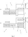
- the tool 6 has moved in the direction of the timer in order to move up the line of products to the downstream end of the timer.
- one of the collectors 8 is synchronized with the batch of products to be picked up, that is to say that the collector is put at the speed of the feed means 4 in the feed direction 3 of the batch 13 of products.
- the rotation speed of the collector is low, possibly almost zero, in order to avoid any imbalance of the captured products.
- the tool resumes a certain speed of rotation combined with a translation speed of the collector to raise the batch of product downstream of the feed means and this preferably with a translation speed of the collector greater than the speed of the feed conveyor.
- the translational movement of the tool 6 along the feed direction contributes to increasing the rate of operation of this transfer device.
- the tool 6 has moved up the line of products downstream of the supply means and by the rotational movement of the collector, the batch of products has been deposited on the output conveyor 9.
- the tool 6 can also perform a transverse movement with respect to the feed direction 3 of the products.
- This transverse movement contributes to facilitate the removal of the products and to increase the range of products which can be treated with the same type of tool.
- the collector restarts the cycle described above.
- THE figures 3a, 3b and 3c describe the stages of the process for orienting products of particular shape, other than cylindrical or whose section is identical to itself once turned by a portion of a turn.
- the speed of the feed means 4 and the speed of the collector 8 along the feed direction 3 are substantially identical. However, depending on the product to be rotated, the speed may vary.
- the products 2 are in line, in a row, on the feed means 4 along a feed direction 3.
- the collector 8 is located parallel to the feed direction, and opposite the products to be oriented.
- the indentations 8 have the shape of a triangle whose apex is formed by two edges. This vertex points towards the products to be oriented when the collector 8 approaches it. According to the feed direction 3, the upstream edge forming the top is the edge on which the product will roll to orient itself.
- the collector translates transversely with respect to the supply direction 4 of the products.
- This translational movement is generated by the rotational movement of tool 6, or even by the additional movement of tool 6 in this direction.
- This translational movement of the notch 10 causes the rotation of the products simultaneously along their vertical axes by pushing on the downstream end of the product 2.
- the translational movement of the notch causes the rotation of the product along its vertical axis by rolling the product on the upstream edge of the top of the notch.
- This product rotation device eliminates the upstream screw used to turn the products.
- Turning screws are tools dedicated to the shape of the products to be turned. They are heavy, imposing and of specific design. In addition, they often cause scratches, scratches or other damage to the surface of the product and its label. Rotating the product by the tool itself helps to eliminate these problems.
Landscapes
- Engineering & Computer Science (AREA)
- Mechanical Engineering (AREA)
- Attitude Control For Articles On Conveyors (AREA)
- Specific Conveyance Elements (AREA)
Claims (8)
- Transfervorrichtung (1) für Produkte (2), die einerseits ein Zuführmittel (4) für die Produkte (2), welches diese hintereinander in einer Zuführrichtung (3) bewegt, und andererseits einen Ausgangsförderer (5), der sich quer zu der Zuführrichtung (3) von dem Zuführmittel (2) erstreckt, beinhaltet,
wobei die Transfervorrichtung ferner ein um eine Rotationsachse (7) parallel zu der Zuführrichtung (3) rotierendes Werkzeug (6) beinhaltet, wobei das Werkzeug (6) Aufnahmeeinheiten (8) aufweist, die radial um die Achse verteilt sind und parallel zu der Zuführrichtung (3) translatorisch beweglich sind, und wobei sich der Ausgangsförderer (5) in einer zu der Zuführrichtung (3) senkrechten Ausgangsrichtung (9) erstreckt, und dadurch gekennzeichnet, dass das Werkzeug (6) in der Ausgangsrichtung (9) bewegbar ist. - Vorrichtung nach Anspruch 1, wobei
jede Aufnahmeeinheit (8) parallel zu der Rotationsachse (7) eine Folge von nebeneinander liegenden Aussparungen (10) aufweist, wobei jede Aussparung (10) dazu bestimmt ist, ein Produkt (2) oder auch mehrere aufzunehmen. - Vorrichtung nach Anspruch 2, wobei
der Boden der Aussparung (10) zwecks eines kontinuierlichen Kontakts während der Rotation des Werkzeugs (6) gewölbt ist. - Vorrichtung nach einem beliebigen der Ansprüche 2 oder 3, wobei
die Aussparung (10) ein Profil aufweist, das während des Schubs hin zu dem Ausgangsförderer (5) unter Einwirkung der Rotation des Werkzeugs (6) die Rotation des Produkts (2) um eine Achse, die sowohl zu der Zuführrichtung (3) als auch der Ausgangsrichtung (9) des Ausgangsförderers (5) senkrecht ist, begünstigt, wobei die Rotation des Produkts (2) dadurch bewirkt wird, dass sich die Aussparung (10) dem Produkt (2) in Bezug auf dessen eigene Symmetrieachse senkrecht zu seiner Basis auf asymmetrische Weise annähern kann. - Vorrichtung nach einem beliebigen der Ansprüche 1 bis 4, dadurch gekennzeichnet, dass
sie Folgendes beinhaltet: ein Gestell (11) auf Basis von Trägern (12) und einerseits einen ersten Motor, der das Werkzeug (6) rotatorisch um die Rotationsachse (7) antreibt und an einem ersten Träger (12) montiert ist, der parallel zu der Rotationsachse (7) beweglich ist und an dem das Werkzeug (6) freitragend und im Wesentlichen vertikal befestigt ist, und andererseits einen zweiten Motor, der den ersten Träger (12) translatorisch entlang eines zweiten, horizontalen Trägers (12) parallel zu der Rotationsachse (7) antreibt. - Transferverfahren für Produkte (2), das Schritte beinhaltet, die darin bestehen, Produkte (2) hintereinander in einer Zuführrichtung (3) zuzuführen, die Produkte (2) durch eine zu der Zuführrichtung (3) quer verlaufende Bewegung in aufeinanderfolgenden Chargen (13) von jeweils mindestens zwei Produkten (2) abzuführen und die Chargen (13) von Produkten (2) in einer zu der Zuführrichtung (3) quer verlaufenden Ausgangsrichtung (9) abzutransportieren, wobei das Verfahren dadurch gekennzeichnet ist, dassdie Abfuhr der Produkte (2) mit Hilfe eines Werkzeugs (6) erfolgt, das eine Rotationsbewegung um eine Rotationsachse (7) parallel zu der Zuführrichtung (3) ausführt, und dadurch gekennzeichnet, dass die Rotationsbewegung von einer Bewegung des Werkzeugs (6) begleitet wird, die der Zufuhr der Produkte (2) gemäß einer Translation parallel zu der Zuführrichtung (3) folgt, und dassdas Werkzeug (6) eine zu der Zuführrichtung (3) quer verlaufende Bewegung ausführt, um die Abfuhr der Produkte (2) hin zu dem Ausgangsförderer (5) zu begleiten.
- Verfahren nach Anspruch 6, dadurch gekennzeichnet, dass
sich die Produkte (2) vertikal und senkrecht sowohl zu der Zuführrichtung (3) als auch der Ausgangsrichtung (9), die zu dieser senkrecht ist, erstrecken, wobei die Bewegung des Werkzeugs (6) entlang der Zuführrichtung (3) während der Abfuhr der Produkte (2) derart ist, dass der Schub des Werkzeugs (6) durch seine Rotation eine Änderung der Ausrichtung der Produkte (2) um ihre vertikale Achse bewirkt. - Verfahren nach einem beliebigen der Ansprüche 6 bis 7, wobei
die Produkte (2) durch das Zuführmittel (4) in Form eines Bandförderers in einer einzelnen Reihe, die sich in der Zuführrichtung (4) erstreckt, zugeführt werden und dann durch das Werkzeug (6) auf den Ausgangsförderer (5) in Chargen (13) abgeführt werden, die sich, gebildet durch den von einer Aufnahmeeinheit (8) des Werkzeugs (6) ausgeübten Querschub, jeweils in der Zuführrichtung (4) erstrecken und die auf dem Ausgangsförderer (5) entlang der Ausgangsrichtung (9) voneinander beabstandet sind.
Applications Claiming Priority (2)
| Application Number | Priority Date | Filing Date | Title |
|---|---|---|---|
| FR1660176A FR3057861B1 (fr) | 2016-10-20 | 2016-10-20 | Transfert de produits |
| PCT/FR2017/052850 WO2018073529A1 (fr) | 2016-10-20 | 2017-10-17 | Transfert de produits |
Publications (2)
| Publication Number | Publication Date |
|---|---|
| EP3529182A1 EP3529182A1 (de) | 2019-08-28 |
| EP3529182B1 true EP3529182B1 (de) | 2023-07-26 |
Family
ID=58401639
Family Applications (1)
| Application Number | Title | Priority Date | Filing Date |
|---|---|---|---|
| EP17794762.9A Active EP3529182B1 (de) | 2016-10-20 | 2017-10-17 | Produkttransfer |
Country Status (5)
| Country | Link |
|---|---|
| US (1) | US10899557B2 (de) |
| EP (1) | EP3529182B1 (de) |
| CN (1) | CN110023213B (de) |
| FR (1) | FR3057861B1 (de) |
| WO (1) | WO2018073529A1 (de) |
Families Citing this family (10)
| Publication number | Priority date | Publication date | Assignee | Title |
|---|---|---|---|---|
| FR3086281B1 (fr) | 2018-09-26 | 2021-10-29 | C E R M E X Constructions Etudes Et Rech De Materiels Pour Lemballage Dexpedition | Dispositif et procede de transfert de produits |
| WO2020229709A1 (es) * | 2019-05-16 | 2020-11-19 | Miguel Torres S.A. | Máquina para rellenar contenedores con un líquido y procedimiento de llenado correspondiente |
| DE102019115198A1 (de) | 2019-06-05 | 2020-12-10 | Krones Aktiengesellschaft | Verfahren und Vorrichtung zum Verteilen und/oder Gruppieren von Behältern |
| FR3098208B1 (fr) * | 2019-07-01 | 2023-10-27 | Semso | Dispositif de convoyage de produits filiformes a grande vitesse et procede de mise en oeuvre |
| CN110712983B (zh) * | 2019-09-11 | 2021-07-06 | 东阿阿胶股份有限公司 | 一种智能供盒流水线的高速伺服电机侧推机构及侧推方法 |
| DE102019126752B4 (de) * | 2019-10-04 | 2024-03-28 | Khs Gmbh | Vorrichtung und Verfahren zur Umwandlung eines einreihigen Produktstroms in einen mehrreihigen Produktstrom |
| CN113814209A (zh) * | 2020-06-19 | 2021-12-21 | 天津龙创恒盛实业有限公司 | 直线导轨清洗线 |
| EP4251854A4 (de) * | 2020-11-27 | 2024-10-30 | Paddlemover LLC | Materialbewegungsvorrichtung |
| CN114229441A (zh) * | 2021-10-20 | 2022-03-25 | 武汉东海敏实汽车零部件有限公司 | 一种密封条自动收料系统 |
| US12595139B1 (en) * | 2024-10-04 | 2026-04-07 | Dyco, Inc. | High-speed array former and methods thereof |
Citations (1)
| Publication number | Priority date | Publication date | Assignee | Title |
|---|---|---|---|---|
| JP3884595B2 (ja) * | 1999-06-14 | 2007-02-21 | 凸版印刷株式会社 | 高速整列供給装置 |
Family Cites Families (21)
| Publication number | Priority date | Publication date | Assignee | Title |
|---|---|---|---|---|
| US1980411A (en) * | 1930-12-11 | 1934-11-13 | Standard Knapp Corp | Article-collecting device |
| US2252937A (en) * | 1937-08-25 | 1941-08-19 | Fred C Link | Lehr loader |
| US3244266A (en) * | 1965-02-24 | 1966-04-05 | Anthony T Zappia | Lehr loader |
| US3710937A (en) * | 1970-12-18 | 1973-01-16 | Ball Corp | Method and apparatus for transporting glassware |
| US3687262A (en) * | 1971-05-24 | 1972-08-29 | Lyman L Campbell | Article handling apparatus |
| JPS5771131U (de) * | 1980-10-17 | 1982-04-30 | ||
| DE4322008C2 (de) * | 1993-07-02 | 1995-07-20 | Smit Ovens Bv | Verfahren und Vorrichtung zum Schieben von Glasgegenständen bei Förderband-Übergängen |
| WO1996013466A1 (de) * | 1994-10-26 | 1996-05-09 | Smit Ovens B.V. | Verfahren und vorrichtung zum schieben von glasgegenständen bei förderband-übergängen |
| DE19847433A1 (de) * | 1998-10-15 | 2000-04-20 | Focke & Co | Vorrichtung zur Erzeugung hin- und hergehender Bewegungen |
| DE20107848U1 (de) * | 2001-05-09 | 2002-02-28 | Braschos, Julian, 57399 Kirchhundem | Überschubeinrichtung für auf Transporteuren beförderten Einheiten |
| US6702097B1 (en) * | 2002-09-04 | 2004-03-09 | Owens-Brockway Glass Container Inc. | Method of and apparatus for transferring articles from a fixed position to a moving conveyor |
| FR2847242B1 (fr) | 2002-11-15 | 2005-11-11 | Cermex Ouest Conditionnement | Machine pour transferer des objets alignes en rangees successives |
| NL1030192C2 (nl) * | 2005-10-14 | 2007-04-17 | Stork Townsend Bv | Inrichting en werkwijze voor het overzetten van langgerekte voedselproducten. |
| FR2918359B1 (fr) | 2007-07-04 | 2009-09-25 | Sidel Participations | Procede de groupage de flacons, bouteilles ou autres |
| FR2940788B1 (fr) | 2009-01-06 | 2011-02-11 | Sidel Participations | Procede de groupage de produits du genre flacons ou autres |
| FR2954756B1 (fr) * | 2009-12-30 | 2012-04-20 | Sidel Participations | Machine de groupage de produits, en vue de leur encaissage |
| CN201670374U (zh) * | 2010-04-14 | 2010-12-15 | 周捷明 | 一种瓶盖包装定量输送装置 |
| ITBO20110654A1 (it) * | 2011-11-18 | 2013-05-19 | Baumer Srl | Sistema per trasferire oggetti fra due linee di trasporto disposte ortogonali fra loro |
| CN203199637U (zh) * | 2013-03-28 | 2013-09-18 | 浙江久而久化学有限公司 | 一种全自动转盘输送装置 |
| US9327914B1 (en) * | 2013-08-22 | 2016-05-03 | Millard Manufacturing Corp. | Rotary sweep arm system |
| EP3305690B1 (de) * | 2016-10-07 | 2019-05-22 | Roche Diagniostics GmbH | Probenbehälterhandhabungsvorrichtung |
-
2016
- 2016-10-20 FR FR1660176A patent/FR3057861B1/fr active Active
-
2017
- 2017-10-17 US US16/343,728 patent/US10899557B2/en active Active
- 2017-10-17 EP EP17794762.9A patent/EP3529182B1/de active Active
- 2017-10-17 WO PCT/FR2017/052850 patent/WO2018073529A1/fr not_active Ceased
- 2017-10-17 CN CN201780073807.XA patent/CN110023213B/zh active Active
Patent Citations (1)
| Publication number | Priority date | Publication date | Assignee | Title |
|---|---|---|---|---|
| JP3884595B2 (ja) * | 1999-06-14 | 2007-02-21 | 凸版印刷株式会社 | 高速整列供給装置 |
Also Published As
| Publication number | Publication date |
|---|---|
| WO2018073529A1 (fr) | 2018-04-26 |
| FR3057861A1 (fr) | 2018-04-27 |
| CN110023213A (zh) | 2019-07-16 |
| FR3057861B1 (fr) | 2018-12-07 |
| CN110023213B (zh) | 2021-03-16 |
| EP3529182A1 (de) | 2019-08-28 |
| US10899557B2 (en) | 2021-01-26 |
| US20190270599A1 (en) | 2019-09-05 |
Similar Documents
| Publication | Publication Date | Title |
|---|---|---|
| WO2018073529A1 (fr) | Transfert de produits | |
| EP3498638B1 (de) | Vorrichtung zur versorgung eines zwischenförderer | |
| EP2559638B1 (de) | Vorrichtung zum Trennen von Früchten | |
| EP2978697B1 (de) | Verfahren und system zum transportieren von objekten | |
| WO2018167437A1 (fr) | Réalisation de lots de produits en vue d'une palettisation par couches | |
| EP3732121A1 (de) | Transfer von produkten zwischen einer durchgangszone und einer sammelfläche | |
| EP3240744B1 (de) | Vorrichtung und verfahren zur zuverlässigen ausgabe von geformten stopperelementen | |
| FR2905118A1 (fr) | Agencement pour la repartition de produits sur un tapis de convoyage a haute cadence | |
| WO2019122591A1 (fr) | Dispositif et procede de positionnement de produits de front ou de cote simultanement a leur convoyage | |
| EP3609821A1 (de) | Mehrlinientransfer von produkten | |
| FR2677626A1 (fr) | Dispositif de transfert d'objets plats, notamment pour machine de tri postal. | |
| FR2501083A1 (fr) | Dispositif pour le tri d'objets entraines par un convoyeur continu, notamment de flacons sur une chaine d'embouteillage | |
| EP3856665A1 (de) | Vorrichtung und verfahren zum transfer von produkten | |
| EP2835184B1 (de) | Vorrichtung zur Trennung von Folien aus einer Masse von Abfällen, und diese Vorrichtung umfassende Sortieranlage | |
| FR2561206A1 (fr) | Procede et appareil equipant une machine de production a marche rapide pour la fabrication d'articles d'hygiene, notamment de garnitures periodiques, protege-slips ou objets analogues | |
| FR2651758A1 (fr) | Procede et dispositif pour faire avancer des produits plats les uns a la suite des autres. | |
| EP0537125A1 (de) | Vorrichtung zum Akkumulieren und Zählen von Gegenständen aus Papier | |
| EP1886945B1 (de) | Verfahren und Vorrichtung zur kontrollierten Verteilung von Schüttgut | |
| FR3018790A1 (fr) | Dispositif et procede de convoyage et ordonnancement | |
| EP2952455B1 (de) | Mehrdrahtige verteilung an seitliche stifte | |
| EP2954990B1 (de) | Vorrichtung zum Perforieren einer Folie | |
| FR3153087A1 (fr) | Dispositif et procédé de transfert de récipients | |
| FR2518054A1 (fr) | Installation pour la pose d'un groupe d'objets, tels que des boites de conserve sur un support en vue de leur emballage |
Legal Events
| Date | Code | Title | Description |
|---|---|---|---|
| STAA | Information on the status of an ep patent application or granted ep patent |
Free format text: STATUS: UNKNOWN |
|
| STAA | Information on the status of an ep patent application or granted ep patent |
Free format text: STATUS: THE INTERNATIONAL PUBLICATION HAS BEEN MADE |
|
| PUAI | Public reference made under article 153(3) epc to a published international application that has entered the european phase |
Free format text: ORIGINAL CODE: 0009012 |
|
| STAA | Information on the status of an ep patent application or granted ep patent |
Free format text: STATUS: REQUEST FOR EXAMINATION WAS MADE |
|
| 17P | Request for examination filed |
Effective date: 20190409 |
|
| AK | Designated contracting states |
Kind code of ref document: A1 Designated state(s): AL AT BE BG CH CY CZ DE DK EE ES FI FR GB GR HR HU IE IS IT LI LT LU LV MC MK MT NL NO PL PT RO RS SE SI SK SM TR |
|
| AX | Request for extension of the european patent |
Extension state: BA ME |
|
| DAV | Request for validation of the european patent (deleted) | ||
| DAX | Request for extension of the european patent (deleted) | ||
| STAA | Information on the status of an ep patent application or granted ep patent |
Free format text: STATUS: EXAMINATION IS IN PROGRESS |
|
| 17Q | First examination report despatched |
Effective date: 20220530 |
|
| GRAP | Despatch of communication of intention to grant a patent |
Free format text: ORIGINAL CODE: EPIDOSNIGR1 |
|
| STAA | Information on the status of an ep patent application or granted ep patent |
Free format text: STATUS: GRANT OF PATENT IS INTENDED |
|
| INTG | Intention to grant announced |
Effective date: 20230220 |
|
| GRAS | Grant fee paid |
Free format text: ORIGINAL CODE: EPIDOSNIGR3 |
|
| GRAA | (expected) grant |
Free format text: ORIGINAL CODE: 0009210 |
|
| STAA | Information on the status of an ep patent application or granted ep patent |
Free format text: STATUS: THE PATENT HAS BEEN GRANTED |
|
| AK | Designated contracting states |
Kind code of ref document: B1 Designated state(s): AL AT BE BG CH CY CZ DE DK EE ES FI FR GB GR HR HU IE IS IT LI LT LU LV MC MK MT NL NO PL PT RO RS SE SI SK SM TR |
|
| P01 | Opt-out of the competence of the unified patent court (upc) registered |
Effective date: 20230620 |
|
| RAP1 | Party data changed (applicant data changed or rights of an application transferred) |
Owner name: SIDEL PARTICIPATIONS |
|
| REG | Reference to a national code |
Ref country code: CH Ref legal event code: EP |
|
| REG | Reference to a national code |
Ref country code: DE Ref legal event code: R096 Ref document number: 602017071847 Country of ref document: DE |
|
| REG | Reference to a national code |
Ref country code: IE Ref legal event code: FG4D Free format text: LANGUAGE OF EP DOCUMENT: FRENCH |
|
| REG | Reference to a national code |
Ref country code: LT Ref legal event code: MG9D |
|
| REG | Reference to a national code |
Ref country code: NL Ref legal event code: MP Effective date: 20230726 |
|
| REG | Reference to a national code |
Ref country code: AT Ref legal event code: MK05 Ref document number: 1591735 Country of ref document: AT Kind code of ref document: T Effective date: 20230726 |
|
| PG25 | Lapsed in a contracting state [announced via postgrant information from national office to epo] |
Ref country code: NL Free format text: LAPSE BECAUSE OF FAILURE TO SUBMIT A TRANSLATION OF THE DESCRIPTION OR TO PAY THE FEE WITHIN THE PRESCRIBED TIME-LIMIT Effective date: 20230726 |
|
| PG25 | Lapsed in a contracting state [announced via postgrant information from national office to epo] |
Ref country code: GR Free format text: LAPSE BECAUSE OF FAILURE TO SUBMIT A TRANSLATION OF THE DESCRIPTION OR TO PAY THE FEE WITHIN THE PRESCRIBED TIME-LIMIT Effective date: 20231027 |
|
| PG25 | Lapsed in a contracting state [announced via postgrant information from national office to epo] |
Ref country code: IS Free format text: LAPSE BECAUSE OF FAILURE TO SUBMIT A TRANSLATION OF THE DESCRIPTION OR TO PAY THE FEE WITHIN THE PRESCRIBED TIME-LIMIT Effective date: 20231126 |
|
| PG25 | Lapsed in a contracting state [announced via postgrant information from national office to epo] |
Ref country code: SE Free format text: LAPSE BECAUSE OF FAILURE TO SUBMIT A TRANSLATION OF THE DESCRIPTION OR TO PAY THE FEE WITHIN THE PRESCRIBED TIME-LIMIT Effective date: 20230726 Ref country code: RS Free format text: LAPSE BECAUSE OF FAILURE TO SUBMIT A TRANSLATION OF THE DESCRIPTION OR TO PAY THE FEE WITHIN THE PRESCRIBED TIME-LIMIT Effective date: 20230726 Ref country code: PT Free format text: LAPSE BECAUSE OF FAILURE TO SUBMIT A TRANSLATION OF THE DESCRIPTION OR TO PAY THE FEE WITHIN THE PRESCRIBED TIME-LIMIT Effective date: 20231127 Ref country code: NO Free format text: LAPSE BECAUSE OF FAILURE TO SUBMIT A TRANSLATION OF THE DESCRIPTION OR TO PAY THE FEE WITHIN THE PRESCRIBED TIME-LIMIT Effective date: 20231026 Ref country code: LV Free format text: LAPSE BECAUSE OF FAILURE TO SUBMIT A TRANSLATION OF THE DESCRIPTION OR TO PAY THE FEE WITHIN THE PRESCRIBED TIME-LIMIT Effective date: 20230726 Ref country code: LT Free format text: LAPSE BECAUSE OF FAILURE TO SUBMIT A TRANSLATION OF THE DESCRIPTION OR TO PAY THE FEE WITHIN THE PRESCRIBED TIME-LIMIT Effective date: 20230726 Ref country code: IS Free format text: LAPSE BECAUSE OF FAILURE TO SUBMIT A TRANSLATION OF THE DESCRIPTION OR TO PAY THE FEE WITHIN THE PRESCRIBED TIME-LIMIT Effective date: 20231126 Ref country code: HR Free format text: LAPSE BECAUSE OF FAILURE TO SUBMIT A TRANSLATION OF THE DESCRIPTION OR TO PAY THE FEE WITHIN THE PRESCRIBED TIME-LIMIT Effective date: 20230726 Ref country code: GR Free format text: LAPSE BECAUSE OF FAILURE TO SUBMIT A TRANSLATION OF THE DESCRIPTION OR TO PAY THE FEE WITHIN THE PRESCRIBED TIME-LIMIT Effective date: 20231027 Ref country code: FI Free format text: LAPSE BECAUSE OF FAILURE TO SUBMIT A TRANSLATION OF THE DESCRIPTION OR TO PAY THE FEE WITHIN THE PRESCRIBED TIME-LIMIT Effective date: 20230726 Ref country code: AT Free format text: LAPSE BECAUSE OF FAILURE TO SUBMIT A TRANSLATION OF THE DESCRIPTION OR TO PAY THE FEE WITHIN THE PRESCRIBED TIME-LIMIT Effective date: 20230726 |
|
| PG25 | Lapsed in a contracting state [announced via postgrant information from national office to epo] |
Ref country code: PL Free format text: LAPSE BECAUSE OF FAILURE TO SUBMIT A TRANSLATION OF THE DESCRIPTION OR TO PAY THE FEE WITHIN THE PRESCRIBED TIME-LIMIT Effective date: 20230726 |
|
| PG25 | Lapsed in a contracting state [announced via postgrant information from national office to epo] |
Ref country code: ES Free format text: LAPSE BECAUSE OF FAILURE TO SUBMIT A TRANSLATION OF THE DESCRIPTION OR TO PAY THE FEE WITHIN THE PRESCRIBED TIME-LIMIT Effective date: 20230726 |
|
| REG | Reference to a national code |
Ref country code: DE Ref legal event code: R097 Ref document number: 602017071847 Country of ref document: DE |
|
| PG25 | Lapsed in a contracting state [announced via postgrant information from national office to epo] |
Ref country code: SM Free format text: LAPSE BECAUSE OF FAILURE TO SUBMIT A TRANSLATION OF THE DESCRIPTION OR TO PAY THE FEE WITHIN THE PRESCRIBED TIME-LIMIT Effective date: 20230726 Ref country code: RO Free format text: LAPSE BECAUSE OF FAILURE TO SUBMIT A TRANSLATION OF THE DESCRIPTION OR TO PAY THE FEE WITHIN THE PRESCRIBED TIME-LIMIT Effective date: 20230726 Ref country code: ES Free format text: LAPSE BECAUSE OF FAILURE TO SUBMIT A TRANSLATION OF THE DESCRIPTION OR TO PAY THE FEE WITHIN THE PRESCRIBED TIME-LIMIT Effective date: 20230726 Ref country code: EE Free format text: LAPSE BECAUSE OF FAILURE TO SUBMIT A TRANSLATION OF THE DESCRIPTION OR TO PAY THE FEE WITHIN THE PRESCRIBED TIME-LIMIT Effective date: 20230726 Ref country code: DK Free format text: LAPSE BECAUSE OF FAILURE TO SUBMIT A TRANSLATION OF THE DESCRIPTION OR TO PAY THE FEE WITHIN THE PRESCRIBED TIME-LIMIT Effective date: 20230726 Ref country code: CZ Free format text: LAPSE BECAUSE OF FAILURE TO SUBMIT A TRANSLATION OF THE DESCRIPTION OR TO PAY THE FEE WITHIN THE PRESCRIBED TIME-LIMIT Effective date: 20230726 Ref country code: SK Free format text: LAPSE BECAUSE OF FAILURE TO SUBMIT A TRANSLATION OF THE DESCRIPTION OR TO PAY THE FEE WITHIN THE PRESCRIBED TIME-LIMIT Effective date: 20230726 |
|
| PG25 | Lapsed in a contracting state [announced via postgrant information from national office to epo] |
Ref country code: MC Free format text: LAPSE BECAUSE OF FAILURE TO SUBMIT A TRANSLATION OF THE DESCRIPTION OR TO PAY THE FEE WITHIN THE PRESCRIBED TIME-LIMIT Effective date: 20230726 |
|
| PLBE | No opposition filed within time limit |
Free format text: ORIGINAL CODE: 0009261 |
|
| REG | Reference to a national code |
Ref country code: CH Ref legal event code: PL |
|
| STAA | Information on the status of an ep patent application or granted ep patent |
Free format text: STATUS: NO OPPOSITION FILED WITHIN TIME LIMIT |
|
| REG | Reference to a national code |
Ref country code: BE Ref legal event code: MM Effective date: 20231031 |
|
| PG25 | Lapsed in a contracting state [announced via postgrant information from national office to epo] |
Ref country code: LU Free format text: LAPSE BECAUSE OF NON-PAYMENT OF DUE FEES Effective date: 20231017 |
|
| GBPC | Gb: european patent ceased through non-payment of renewal fee |
Effective date: 20231026 |
|
| PG25 | Lapsed in a contracting state [announced via postgrant information from national office to epo] |
Ref country code: LU Free format text: LAPSE BECAUSE OF NON-PAYMENT OF DUE FEES Effective date: 20231017 |
|
| 26N | No opposition filed |
Effective date: 20240429 |
|
| PG25 | Lapsed in a contracting state [announced via postgrant information from national office to epo] |
Ref country code: GB Free format text: LAPSE BECAUSE OF NON-PAYMENT OF DUE FEES Effective date: 20231026 |
|
| PG25 | Lapsed in a contracting state [announced via postgrant information from national office to epo] |
Ref country code: CH Free format text: LAPSE BECAUSE OF NON-PAYMENT OF DUE FEES Effective date: 20231031 |
|
| PG25 | Lapsed in a contracting state [announced via postgrant information from national office to epo] |
Ref country code: GB Free format text: LAPSE BECAUSE OF NON-PAYMENT OF DUE FEES Effective date: 20231026 Ref country code: CH Free format text: LAPSE BECAUSE OF NON-PAYMENT OF DUE FEES Effective date: 20231031 Ref country code: SI Free format text: LAPSE BECAUSE OF FAILURE TO SUBMIT A TRANSLATION OF THE DESCRIPTION OR TO PAY THE FEE WITHIN THE PRESCRIBED TIME-LIMIT Effective date: 20230726 |
|
| PG25 | Lapsed in a contracting state [announced via postgrant information from national office to epo] |
Ref country code: BE Free format text: LAPSE BECAUSE OF NON-PAYMENT OF DUE FEES Effective date: 20231031 |
|
| PG25 | Lapsed in a contracting state [announced via postgrant information from national office to epo] |
Ref country code: IE Free format text: LAPSE BECAUSE OF NON-PAYMENT OF DUE FEES Effective date: 20231017 |
|
| PG25 | Lapsed in a contracting state [announced via postgrant information from national office to epo] |
Ref country code: IE Free format text: LAPSE BECAUSE OF NON-PAYMENT OF DUE FEES Effective date: 20231017 |
|
| PG25 | Lapsed in a contracting state [announced via postgrant information from national office to epo] |
Ref country code: BG Free format text: LAPSE BECAUSE OF FAILURE TO SUBMIT A TRANSLATION OF THE DESCRIPTION OR TO PAY THE FEE WITHIN THE PRESCRIBED TIME-LIMIT Effective date: 20230726 |
|
| PG25 | Lapsed in a contracting state [announced via postgrant information from national office to epo] |
Ref country code: BG Free format text: LAPSE BECAUSE OF FAILURE TO SUBMIT A TRANSLATION OF THE DESCRIPTION OR TO PAY THE FEE WITHIN THE PRESCRIBED TIME-LIMIT Effective date: 20230726 |
|
| PG25 | Lapsed in a contracting state [announced via postgrant information from national office to epo] |
Ref country code: IT Free format text: LAPSE BECAUSE OF NON-PAYMENT OF DUE FEES Effective date: 20231017 |
|
| PG25 | Lapsed in a contracting state [announced via postgrant information from national office to epo] |
Ref country code: IT Free format text: LAPSE BECAUSE OF NON-PAYMENT OF DUE FEES Effective date: 20231017 |
|
| PG25 | Lapsed in a contracting state [announced via postgrant information from national office to epo] |
Ref country code: CY Free format text: LAPSE BECAUSE OF FAILURE TO SUBMIT A TRANSLATION OF THE DESCRIPTION OR TO PAY THE FEE WITHIN THE PRESCRIBED TIME-LIMIT; INVALID AB INITIO Effective date: 20171017 |
|
| PG25 | Lapsed in a contracting state [announced via postgrant information from national office to epo] |
Ref country code: HU Free format text: LAPSE BECAUSE OF FAILURE TO SUBMIT A TRANSLATION OF THE DESCRIPTION OR TO PAY THE FEE WITHIN THE PRESCRIBED TIME-LIMIT; INVALID AB INITIO Effective date: 20171017 |
|
| PGFP | Annual fee paid to national office [announced via postgrant information from national office to epo] |
Ref country code: FR Payment date: 20250924 Year of fee payment: 9 |
|
| PG25 | Lapsed in a contracting state [announced via postgrant information from national office to epo] |
Ref country code: TR Free format text: LAPSE BECAUSE OF FAILURE TO SUBMIT A TRANSLATION OF THE DESCRIPTION OR TO PAY THE FEE WITHIN THE PRESCRIBED TIME-LIMIT Effective date: 20230726 |
|
| PGFP | Annual fee paid to national office [announced via postgrant information from national office to epo] |
Ref country code: DE Payment date: 20250923 Year of fee payment: 9 |