EP3529435B1 - Dispositif clé pour faire fonctionner des serrures - Google Patents
Dispositif clé pour faire fonctionner des serrures Download PDFInfo
- Publication number
- EP3529435B1 EP3529435B1 EP17835489.0A EP17835489A EP3529435B1 EP 3529435 B1 EP3529435 B1 EP 3529435B1 EP 17835489 A EP17835489 A EP 17835489A EP 3529435 B1 EP3529435 B1 EP 3529435B1
- Authority
- EP
- European Patent Office
- Prior art keywords
- block
- defender
- manipulator head
- flat key
- fact
- Prior art date
- Legal status (The legal status is an assumption and is not a legal conclusion. Google has not performed a legal analysis and makes no representation as to the accuracy of the status listed.)
- Active
Links
Images
Classifications
-
- E—FIXED CONSTRUCTIONS
- E05—LOCKS; KEYS; WINDOW OR DOOR FITTINGS; SAFES
- E05B—LOCKS; ACCESSORIES THEREFOR; HANDCUFFS
- E05B17/00—Accessories in connection with locks
- E05B17/14—Closures or guards for keyholes
-
- E—FIXED CONSTRUCTIONS
- E05—LOCKS; KEYS; WINDOW OR DOOR FITTINGS; SAFES
- E05B—LOCKS; ACCESSORIES THEREFOR; HANDCUFFS
- E05B27/00—Cylinder locks or other locks with tumbler pins or balls that are set by pushing the key in
- E05B27/02—Cylinder locks or other locks with tumbler pins or balls that are set by pushing the key in operated by the edge of the key
- E05B27/08—Cylinder locks or other locks with tumbler pins or balls that are set by pushing the key in operated by the edge of the key arranged axially
- E05B27/083—Cylinder locks or other locks with tumbler pins or balls that are set by pushing the key in operated by the edge of the key arranged axially of the split-pin tumbler type
-
- E—FIXED CONSTRUCTIONS
- E05—LOCKS; KEYS; WINDOW OR DOOR FITTINGS; SAFES
- E05B—LOCKS; ACCESSORIES THEREFOR; HANDCUFFS
- E05B35/00—Locks for use with special keys or a plurality of keys ; keys therefor
- E05B35/008—Locks for use with special keys or a plurality of keys ; keys therefor for simple tool-like keys
-
- E—FIXED CONSTRUCTIONS
- E05—LOCKS; KEYS; WINDOW OR DOOR FITTINGS; SAFES
- E05B—LOCKS; ACCESSORIES THEREFOR; HANDCUFFS
- E05B9/00—Lock casings or latch-mechanism casings ; Fastening locks or fasteners or parts thereof to the wing
- E05B9/10—Coupling devices for the two halves of double cylinder locks, e.g. devices for coupling the rotor with the locking cam
-
- E—FIXED CONSTRUCTIONS
- E05—LOCKS; KEYS; WINDOW OR DOOR FITTINGS; SAFES
- E05B—LOCKS; ACCESSORIES THEREFOR; HANDCUFFS
- E05B15/00—Other details of locks; Parts for engagement by bolts of fastening devices
- E05B15/10—Bolts of locks or night latches
- E05B15/108—Bolts with multiple head
Definitions
- the invention falls within the technical sector of high-security locks according to claim 1.
- keyless mechanical locks for example featuring combination dials such as those on safes
- keyless electronic locks featuring keypads with alphanumeric combination, or with transponders, cards with embedded chips (for example those used for hotel rooms), or further still featuring fingerprint recognition or, for the most sophisticated versions, iris recognition.
- the common denominator of the locks of a predominantly mechanical nature lies in the fact that there is a key, to be introduced in the related keyhole, more or less protected but accessible from outside, where the same key, if bearing the correct combination, acts directly for unblocking the mechanism linked to the retention devices, such as bolts, and controls the rotation in the direction of opening or closing.
- the key represents both an opening device and a protection system; if one manages to bypass the latter, the lock is violated.
- the purpose of this invention is therefore that of proposing a keyed device for operating locks, in particular combinable with euro profile cylinders, for example featuring the European profile, which makes it possible to overcome the traditional construction concept of known locks, which sees the key as the mechanical connection device which receives the manual act and directly transmits the opening (and/or closing) action to the mechanism, in this way avoiding all the inconveniences and risks associated with security which afflict the afore-mentioned well-known locks.
- Another purpose of the invention involves envisaging a lock which is inaccessible from outside, and also protected against attacks of elevated force, in particular for that which concerns the area in which the particular key of the device presents its cuts to the mechanical combination means which must attest to the compliance, so as to permit the subsequent opening manoeuvre.
- Another purpose of the invention concerns the desire to prevent any action aimed at the reverse detection of the correct combination cut of the key, thanks to the afore-mentioned inaccessibility of the area.
- a further purpose of the invention envisages that the parts tasked with the passive protection of the lock, or rather those exposed to attack with devices such as drills, cutting disks or similar, can be suitably scaled, and in a variable manner according to the degree of resistance desired, as well as made of material appropriately treated to resist the cutting and/or drilling action.
- Another additional purpose of the invention aims to obtain a key which can be contaihed and protected in a portable element, with said key destined to be detached from the latter so as to be inserted, in a retractable manner, in the device which is suitable for being operated by the same portable element, grasped like a device.
- a keyed device for operating locks in particular incorporating euro profile cylinders, suitable for installation on security doors, armoured doors and the like, comprising at least one cylinder-operated deadbolt and a euro profile cylinder in which a cam can be rotated in either direction, respectively to open or close at least one deadbolt, since the following is envisaged in said device:
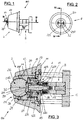
- the keyed device (100) is suitable for being associated with locks (S), in combination with euro profiled cylinders (E), in particular those with so-called "European" profile.
- These locks (S), with the related cylinders (E), are suitable for being installed on security doors of homes and offices, armoured doors of safes or security lockers, and the like (not illustrated), and comprising at least one deadbolt (P) with lock operated by a cam (C) of the cylinder (E) (specifically see Dwg. 12).
- the cam (C) is rotated in either direction, respectively to open or close said deadbolt (P), via the mechanisms of the aforementioned lock (S).
- the device (100) includes a (1) mechanism for operating said cam (C), in which the following is envisaged:
- the actuator plug (10) can slide axially, in opposition to the reaction of spring-loaded components (13), while the manipulator head (11) is inserted rotating in a cylindrical compartment (14) situated in a flange (15), with the latter integral to the afore-mentioned euro profile cylinder (E).
- the mechanical combination means (12) are advantageously made up of a number of combination pins (120) (of which only two visible in Dwg. 3), housed inside said manipulator head (11) and arranged in a circle according to a predefined geometry, for example a circumference, with the respective axes parallel to that of the manipulator head (11).
- each of the combination pins (120) protrude from the rear of the manipulator head (11) beyond the end of the cylindrical compartment (14) and are partially inserted into corresponding holes (16) situated in the flange (15); each of the combination pins (120) is made up of two consecutive parts, the first (121) and the second (122).
- the total emerging length of each combination pin (120) can be the same or differ with respect to that of the remaining pins (120), as can the length of the first part (121) with respect to the second part (122), or with respect to those of the other pins (120).
- At least one of the afore-mentioned combination pins (120) includes a third part (123), for example a spheroid, placed between said first and second parts (121) (122) (Dwg. 3).
- the insertion or removal of the third part (123) makes it possible, conveniently, to modify the combination cuts of the mechanical combination means (12) at a later stage.
- Each combination pin (120) in two parts (121) (122) (or three), is subject to the action of the spring-loaded components (124) inserted in the related hole (16), which drive it axially to protrude from the front side of the manipulator head (11), up until a pre-established position defined by a stop (17) envisaged in the latter.
- the device (100) also comprises an opening/closing assembly (2), accessible from the external side of the afore-mentioned security doors, armoured dolors and the like, intended to operate on the afore-mentioned manipulator head (11) and on the mechanical combination means (12).
- the opening/closing assembly (2) comprises an outer shell (20), incorporating an axial pass-through cylindrical seat (21) that houses a rotor (22) coaxial with said manipulator head (11) and the actuator plug (10).
- the outer shell (20), solidly and robustly constructed in highly-resistant steel, is integral with said euro profile cylinder (E) and protrudes at least partially outward from the related security door, armoured door, or the like.
- the outer shell (20) is ring-shaped and externally formed with decreasing cross-section moving outward from said door, armoured door, or the like, for example tapered as illustrated in the drawings.
- the rotor (22) is able to slide axially toward the manipulator head (11), in opposition to the spring-loaded components (23) which retain it, when at rest, against a shoulder (24) within the afore-mentioned seat (21).
- the shoulder (24) has a lesser diameter than that of the axial cylindrical seat (21) and is situated near the outermost end of the cylindrical seat.
- a defender block (25), for impeding external access to the manipulator head (11), is supported rotating, by a pin (25P) with an axis perpendicular to the rotation of the rotor (22).
- the defender block (25) is conveniently made of highly-resistant steel, for example in alloy with molybdenum and vanadium, capable of granting the same elevated anti lock-picking and anti-drilling properties.
- the defender block (25) is partially accessible externally and close to said manipulator head (11) with the respective internal part, and in the related lateral surface area presents a first profiled face (251) that can be stably paired with a removable flat key (26), and a second profiled face (252), diametrically opposite to the first, which can be provisionally paired with an opening/closing device (27).
- the aforesaid defender block (25) has an essentially spherical shape where at least the first profiled face (251) is flattened and parallel to the rotation axis of the block (25) itself.
- the latter is composed of two parts (22A, 22B), joined to each other by said rotation pin (25P) of the defender block (25) (Dwgs. 3 and 4).
- the defender block (25) is envisaged to rotate between at least two characteristic positions, one where the first profiled face (251) is turned outward and can receive the flat key (26).
- the first profiled face (251) is turned towards the manipulator head (11) while the second profiled face (252) is turned outward and can receive said opening/closing device (27).
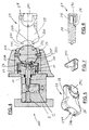
- a male dovetail profile (261) is envisaged, which can engage with a complementary female dovetail profile (262) on the back of the flat key (26) to achieve the stable removable coupling between it and said block (25).
- At least two dead holes (272) are envisaged, parallel to each other and parallel and symmetrically off-centre from the rotation axis of said rotor (22).
- the two afore-mentioned dead holes (272) are there to accommodate corresponding plugs (270) protruding from the opening/closing device (27), to accomplish the provisional coupling between it and the defender block (25) (see in particular Dwg. 4).
- the flat key (26), illustrated in the drawings from 8 to 11 and adapted for the spherical defender block (25), has an outer face shaped like a spherical cap, with radius equal to that of the block (25), so as to restore the continuity of the spherical shape when they are joined together.
- the same spherical cap-shaped outer face of the flat key (26) comprises a number of combination holes (260), of differing lengths, arranged in a circle according to a predefined geometry, for example a circumference, with their axes parallel to each other.
- the combination holes (260) are destined to be directed toward the manipulator head (11) and parallel to its axis in concomitance with said second position of the defender block (25), and are suitable for engaging with the corresponding combination pins (120) protruding from the manipulator head (11) to push them along their predefined routes envisaged to release the head, as more fully explained further on.
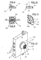
- the lateral surface of the defender block (25) envisages a number of notches (25T), that can be gripped by a fingernail or flat-blade tool, to facilitate the rotation of the block (25) between its two characteristic positions (Dwgs. 1, 2, 12).
- respective centring means (30) have been envisaged, represented in the example by an initial circular cavity (31) made in the centre of the flat key (26) and a second circular cavity (32), identical to the first, made in the centre of the second profiled face (252).
- Each cavity (31, 32), in relation to the position adopted by the defender block (25), is alternatively destined to elastically engage with a reference situated in the manipulator head (11), for example the headend of the actuator plug (10), protruding slightly from the latter.
- the afore-mentioned defender block (25) has an essentially cylindrical shape whose axis coincides with the rotation axis of the block (25) itself; likewise, at least the first profiled face (251) is flattened and parallel to the rotation axis.
- the defender block (25) has an essentially prismatic shape whose longitudinal axis coincides with the rotation axis of the block (25) itself, and where the first and second profiled faces (251, 252) coincide with the corresponding lateral faces of the prism.
- Dwgs. 4, 5, 6, 7 illustrate the opening/closing device (27) in the form adapted for the described preferred form for creating the defender block (25).
- the opening/closing device (27) can house, within it, the flat key (26) for the transportation of the same, placed in such a way so that the back is presented with the female dovetail profile (262) turned outward.
- the opening/closing device (27) has a main body (28), shaped to provide an ergonomic grip for the fingers of one hand, which envisages: a compartment (29) for holding, retaining and transporting the flat key (26); a cover (29C) for the closure, at least partial, of said compartment (29); coupling means (271) consisting of a cavity shaped to match the second profiled face (252) of the defender block (25) and at least two parallel plugs (270).
- the cover (29C) (Dwg. 7) is extractable, but it is possible to envisage a version in which the same is joined via hinge to the main body (28).
- the cavity of the coupling means (271) adopts a concave form with a spherical radius equal to that of the defender block (25) and contains, appropriately positioned and protruding outward, the afore-mentioned plugs (270) which, as already mentioned above, can be inserted in the aforesaid dead holes (272) in the second profiled! face (252), so as to accomplish the provisional coupling between said device (27) and the defender block (25).
- the flat key (26) remains stably engaged in the defender block (25), which is subsequently rotated, again with the possible aid of the notches (25T), in its afore-mentioned second position, in which the same flat key (26) is drawn inside, in front of the manipulator head (11).
- the plugs (270) engage in the dead holes (272) of the second profiled face (252), until the concave cavity joins the spherical defender block (25).
- Another advantage derives from having made the area in which the flat key of the device presents its cuts to the mechanical combination means inaccessible from outside, as well as well protected from attacks of elevated force.
- the construction-related aspect just mentioned also prevents any action aimed at the reverse detection of the correct combination cut of the key, with a considerable increase in security.
- the structure of the keyed device described makes it possible to combine it with additional accessory devices, both mechanical and electromechanical, aimed at further increasing the security of the same.
Landscapes
- Engineering & Computer Science (AREA)
- Mechanical Engineering (AREA)
- Lock And Its Accessories (AREA)
- Manipulator (AREA)
Claims (15)
- Dispositif à clé pour l'actionnement de serrures (S) équipées de cylindres (E) à profil standard européen, lesdites serrures convenant pour être installées sur des portes blindées, de sécurité et similaires, et comprenant au moins un pêne dormant (P) à manœuvre par cylindre, où ledit cylindre (E) comprend une came (C) qui peut être actionnée en rotation dans un sens comme dans l'autre pour entraîner respectivement, l'ouverture ou la fermeture d'au moins un pêne dormant (P), ledit dispositif (100) comprenant :- un groupe d'actionnement (1) de ladite came (C), comprenant: un arbre de commande (10), placé à l'intérieur dudit cylindre européen (E) et coaxial à l'axe de rotation de ladite came (C), prévu pour engager cette came dans un mouvement de rotation ; une tête de manœuvre (11), associée audit arbre de commande (10) et prévue pour actionner ce dernier en rotation ; des moyens à combinaison mécanique (12) pour verrouiller et déverrouiller la rotation de ladite tête de manœuvre (11) et de l'arbre de commande qui y est associé (10) ;- un groupe d'ouverture/fermeture (2) accessible du côté extérieur desdites portes blindées, de sécurité et similaires, prévu pour actionner ladite tête de manœuvre (11) et lesdits moyens à combinaison mécanique (12), ledit groupe d'ouverture/fermeture (2) comprenant : une coquille externe (20) pourvue d'un siège cylindrique axial et traversant (21) caractérisé en ce qu'il abrite un rotor (22) coaxial à ladite tête de manœuvre (11) et audit arbre de commande (10), ce même rotor (22) pouvant se déplacer dans le sens axial vers ladite tête de manœuvre (11) en s'opposant à l'action d'organes élastiques (23) en mesure de maintenir le rotor, lorsqu'il est au repos, en butée sur un épaulement (24) réalisé dans ledit siège (21) ; un bloc de protection (25) prévu pour empêcher l'accès de l'extérieur à ladite tête de manœuvre (11), soutenu par un goujon (25P) à l'intérieur dudit rotor (22), pouvant tourner sur un axe perpendiculaire à l'axe de rotation du rotor (22) lui-même, ledit bloc de protection (25) étant partiellement accessible de l'extérieur et proche de ladite tête de manœuvre (11) du côté de sa partie interne, où ledit bloc de protection (25) comprend une première face profilée (251) qui peut être couplée de manière stable à une clé à plaquette amovible (26), et une deuxième face profilée (252), diamétralement opposée à la première, qui peut être couplée de manière provisoire à un outil d'ouverture/fermeture (27), le bloc de protection (25) étant prévu pour tourner sur deux positions caractéristiques au moins, la première où ladite première face profilée (251) est tournée vers l'extérieur et peut recevoir ladite clé à plaquette (26), et la deuxième où ladite première face profilée (251) est tournée vers ladite tête de manœuvre (11) tandis que ladite deuxième face profilée (252) est tournée vers l'extérieur et peut recevoir ledit outil d'ouverture/fermeture (27), ce dernier pouvant être actionné manuellement pour entraîner : la translation axiale de l'ensemble rotor-bloc-clé à plaquette (22, 25, 26), cette dernière étant positionnée pour s'accoupler avec lesdits moyens à combinaison mécanique (12) pour débloquer la rotation de ladite tête de manœuvre (11) ; la rotation, dans un sens ou dans l'autre, de l'ensemble rotor-bloc-clé à plaquette-tête de manœuvre-arbre de commande (22, 25, 26, 11, 10), avec par conséquent la rotation dans le même sens de ladite came (C) pour l'ouverture ou la fermeture de ladite serrure (S).
- Dispositif à clé selon la revendication 1, caractérisé en ce que ledit arbre de commande (10) dans ledit groupe d'actionnement (1) peut coulisser dans le sens axial, en opposition à la réaction d'organes élastiques (13), en phase avec ladite translation axiale de l'ensemble rotor-bloc-clé à plaquette (22, 25, 26), où ladite tête de manœuvre (11) est insérée de manière à tourner dans un logement cylindrique (14) réalisé dans une bride (15) solidaire dudit cylindre européen (E), et où lesdits moyens à combinaison mécanique (12) sont constitués d'un certain nombre de goupilles de combinaison (120), logées à l'intérieur de ladite tête de manœuvre (11), disposées en cercle selon une géométrie préétablie, leurs axes respectifs étant parallèles à celui de la tête de manœuvre (11) elle-même, et faisant saillie à l'arrière de cette dernière au-delà du fond dudit logement cylindrique (14) et partiellement insérées dans des trous correspondants (16) réalisés dans ladite bride (15), chacune desdites goupilles de combinaison (120) étant constituée de deux parties consécutives, une première (121) et une deuxième (122), de sorte que la longueur totale résultante peut être homogène ou différente de celle des goupilles restantes (120), la goupille de combinaison (120) constituée de deux parties (121, 122) étant soumise à l'action d'organes élastiques (124) et poussée dans le sens axial, en opposition à ces derniers, pour une course préétablie déterminée par le codage de ladite clé à plaquette (26), jusqu'à une position où le plan diamétral, sur lequel la première et la deuxième partie des goupilles (121, 122) se rejoignent, est coplanaire audit fond du logement cylindrique (14), permettant ainsi à ladite tête de manœuvre (11) de tourner en même temps que ledit arbre de commande (10), en séparant de manière angulaire toutes les premières parties (121) des goupilles de combinaison (120) de leurs deuxièmes parties (122), qui restent à l'intérieur desdits trous (16) dans la bride (15).
- Dispositif à clé selon la revendication 1, caractérisé en ce que ladite coquille externe (20) dans ledit groupe d'ouverture/fermeture (2), est rendue solidaire dudit cylindre européen (E) et fait saillie au moins partiellement vers l'extérieur d'une porte blindée, de sécurité ou similaire, la coquille externe (20) étant de forme annulaire et profilée selon une section décroissante vers l'extérieur de ladite porte blindée, de sécurité ou similaire, et en ce que l'épaulement (24) présente un diamètre réduit par rapport au diamètre dudit siège cylindrique axial (21) et qu'il est réalisé en correspondance de l'extrémité extérieure de ce dernier.
- Dispositif à clé selon la revendication 1, caractérisé en ce que ledit bloc de protection (25) présente une forme essentiellement sphérique où ladite première face profilée au moins (251) est aplatie et parallèle à l'axe de rotation du bloc (25) lui-même.
- Dispositif à clé selon la revendication 1 ou la revendication 4, caractérisé en ce que ladite clé à plaquette (26) présente un côté extérieur profilé en forme de calotte sphérique, dont le rayon est égal au rayon dudit bloc (25), de manière à ce que la forme sphérique soit rétablie lorsque la clé est couplée audit bloc, et où le même côté extérieur de la clé à plaquette (26) comprend un certain nombre de trous de codage (260), de différentes profondeurs, disposés en cercle selon une géométrie préétablie, leurs axes respectifs étant mutuellement parallèles, et qui sont tournés vers ladite tête de manœuvre (11), mais aussi parallèles à l'axe de cette tête, en phase avec ladite deuxième position du bloc de protection (25), lesdits trous de codage (260) s'accouplant avec les goupilles de combinaison correspondantes (120) qui font saillie de ladite tête de manœuvre (11) pour pousser ces goupilles selon les courses préétablies prévues pour déverrouiller la tête.
- Dispositif à clé selon la revendication 1 ou la revendication 4, caractérisé en ce que ledit rotor (22) est constitué de deux pièces (22A, 22B), rendues mutuellement solidaires par ledit goujon de rotation (25P) du bloc de protection (25).
- Dispositif à clé selon la revendication 1, caractérisé en ce que ledit bloc de protection (25) présente une forme essentiellement cylindrique, son axe coïncidant avec l'axe de rotation dudit bloc (25) et où ladite première face profilée au moins (251) est aplatie et parallèle audit axe de rotation.
- Dispositif à clé selon la revendication 1, caractérisé en ce que ledit bloc de protection (25) présente une forme essentiellement prismatique, son axe longitudinal coïncidant avec l'axe de rotation dudit bloc (25) et où lesdites première et deuxième faces profilées (251, 252) coïncident avec les faces latérales correspondantes dudit prisme.
- Dispositif à clé selon l'une quelconque des revendications précédentes, caractérisé en ce qu'il comprend un certain nombre d'encoches (25T) sur la surface latérale dudit bloc de protection (25), encoches qui peuvent être agrippées avec l'ongle ou un outil à lame plate pour entraîner la rotation dudit bloc (25) sur ses deux positions caractéristiques.
- Dispositif à clé selon l'une quelconque des revendications précédentes, caractérisé en ce que ladite première face profilée (251) du bloc de protection (25) comprend un profil mâle à queue d'aronde (261), auquel peut s'accoupler de manière complémentaire un profil femelle à queue d'aronde (262), réalisé au dos de ladite clé à plaquette (26) pour créer ledit accouplement stable et amovible de cette clé avec le bloc (25) lui-même.
- Dispositif à clé selon l'une quelconque des revendications précédentes, caractérisé en ce que ladite deuxième face profilée (252) du bloc de protection (25) comprend deux trous borgnes (272) au moins, mutuellement parallèles, mais aussi symétriquement décentrés par rapport à l'axe de rotation dudit rotor (22), lesdits deux trous borgnes (272) au moins pouvant recevoir les broches correspondantes (270) qui font saillie dudit outil d'ouverture/fermeture (27), pour entraîner ledit accouplement provisoire de ce dernier avec le bloc (25).
- Dispositif à clé selon l'une quelconque des revendications précédentes, caractérisé en ce que ladite clé à plaquette (26) et ladite deuxième face profilée (252) comprennent des moyens de centrage respectifs (30), identiques entre eux, pouvant s'engager alternativement de manière élastique dans un repère présent sur ladite tête de manœuvre (11), pour réaliser et stabiliser lesdites deux positions caractéristiques du bloc de protection (25).
- Dispositif à clé selon l'une quelconque des revendications précédentes, caractérisé en ce que le corps principal (28) dudit outil d'ouverture/fermeture (27) comprend un logement (29) pour recevoir, retenir et transporter ladite clé à plaquette (26), et un couvercle (29C) pour fermer, au moins partiellement, ledit logement (29).
- Clé à plaquette (26) à utiliser avec un dispositif à clé (100) pour actionner les serrures (S) selon l'une quelconque des revendications de 1 à 10, caractérisée en ce qu' elle comprend : un certain nombre de trous de codage (260), de différentes profondeurs, disposés en cercle selon une géométrie préétablie, ayant leurs axes parallèles les uns par rapport aux autres, et qui peuvent être orientés vers ladite tête de manœuvre (11), et parallèles à l'axe de celle-ci, en phase avec ladite deuxième position du bloc de protection (25), lesdits trous de codage (260) s'accouplant avec les goupilles de combinaison (120) correspondantes qui dépassent de ladite tête de manoeuvre (11) pour pousser ces goupilles selon les courses préétablies prévues pour déverrouiller la tête ; un profil femelle à queue d'aronde (262), réalisé au dos de ladite clé à plaque (26), pouvant s'accoupler avec un profil mâle à queue d'aronde complémentaire (261), réalisé dans ledit bloc de protection (25) pour créer entre eux un accouplement stable et amovible.
- Outil d'ouverture/fermeture (27) à utiliser avec un dispositif à clé (100) pour actionner des serrures (S) selon l'une quelconque des revendications de 1 à 10, caractérisé en ce qu'il présente un corps principal (28), profilé de manière à créer une prise ergonomique pour les doigts d'une main et comprenant : un logement (29) pour recevoir, retenir et transporter ladite clé à plaquette (26) ; des moyens d'accouplement (271) constitués d'une empreinte de forme complémentaire à ladite deuxième face profilée (252) du bloc de protection (25) et d'au moins deux broches (270) parallèles, faisant saillie vers l'extérieur et pouvant s'engager dans les trous borgnes correspondants (272) réalisés dans la même deuxième face profilée (252), pour créer ledit accouplement provisoire entre ledit outil (27) et le bloc (25).
Applications Claiming Priority (2)
| Application Number | Priority Date | Filing Date | Title |
|---|---|---|---|
| IT102016000105693A IT201600105693A1 (it) | 2016-10-20 | 2016-10-20 | Dispositivo a chiave per l'azionamento di serrature |
| PCT/IB2017/001278 WO2018073641A1 (fr) | 2016-10-20 | 2017-10-20 | Dispositif à clavette de mise en œuvre de serrures |
Publications (2)
| Publication Number | Publication Date |
|---|---|
| EP3529435A1 EP3529435A1 (fr) | 2019-08-28 |
| EP3529435B1 true EP3529435B1 (fr) | 2020-10-14 |
Family
ID=58010252
Family Applications (1)
| Application Number | Title | Priority Date | Filing Date |
|---|---|---|---|
| EP17835489.0A Active EP3529435B1 (fr) | 2016-10-20 | 2017-10-20 | Dispositif clé pour faire fonctionner des serrures |
Country Status (4)
| Country | Link |
|---|---|
| EP (1) | EP3529435B1 (fr) |
| CN (1) | CN109863278B (fr) |
| IT (1) | IT201600105693A1 (fr) |
| WO (1) | WO2018073641A1 (fr) |
Families Citing this family (1)
| Publication number | Priority date | Publication date | Assignee | Title |
|---|---|---|---|---|
| US12435544B2 (en) * | 2022-06-30 | 2025-10-07 | Dirak Dieter Ramsauer Konstruktionselemente Gmbh | Magnetically coded lock |
Family Cites Families (11)
| Publication number | Priority date | Publication date | Assignee | Title |
|---|---|---|---|---|
| DE667248C (de) * | 1934-09-04 | 1938-11-08 | Helene Sewoll Geb Schlitz | Schloss |
| US3630053A (en) * | 1970-04-01 | 1971-12-28 | Edwin G Krakauer | Safety lock |
| US3680337A (en) * | 1971-03-09 | 1972-08-01 | Edwin G Krakauer | Safety lock |
| IT977537B (it) * | 1973-02-27 | 1974-09-20 | Jacovacci A | Serratura di sicurezza |
| US4006615A (en) * | 1975-08-07 | 1977-02-08 | Janos Szova | Axial tumbler lock |
| DE29619390U1 (de) * | 1996-01-23 | 1997-03-20 | Kolb, Horst, 93049 Regensburg | Bedieneinrichtung für Vorsatzschlösser von Schloßzylindern |
| US5934122A (en) * | 1998-05-20 | 1999-08-10 | Sure-Wood Lock, Inc. | Locking cover for dead bolt actuators |
| US6393883B1 (en) * | 2000-03-02 | 2002-05-28 | Royal Lock Corp. | Tubular keyed cam lock with screw attachment |
| FR2882463B1 (fr) * | 2005-02-24 | 2007-03-30 | Schneider Electric Ind Sas | Bouton tournant a serrure |
| CN201053250Y (zh) * | 2007-06-26 | 2008-04-30 | 赵北华 | 带钥匙输送器的门插锁 |
| GB2512274A (en) * | 2013-02-08 | 2014-10-01 | William Frederick Crosbie | Rotational pin lock |
-
2016
- 2016-10-20 IT IT102016000105693A patent/IT201600105693A1/it unknown
-
2017
- 2017-10-20 EP EP17835489.0A patent/EP3529435B1/fr active Active
- 2017-10-20 CN CN201780064689.6A patent/CN109863278B/zh not_active Expired - Fee Related
- 2017-10-20 WO PCT/IB2017/001278 patent/WO2018073641A1/fr not_active Ceased
Non-Patent Citations (1)
| Title |
|---|
| None * |
Also Published As
| Publication number | Publication date |
|---|---|
| IT201600105693A1 (it) | 2018-04-20 |
| EP3529435A1 (fr) | 2019-08-28 |
| CN109863278B (zh) | 2020-10-16 |
| WO2018073641A1 (fr) | 2018-04-26 |
| CN109863278A (zh) | 2019-06-07 |
Similar Documents
| Publication | Publication Date | Title |
|---|---|---|
| US9556651B1 (en) | Electronic sensor and key operated lock | |
| US10422163B1 (en) | Electronic sensor and key operated lock | |
| EP2942456B1 (fr) | Serrure antivol | |
| CN102971469A (zh) | 锁具机构 | |
| US20110067461A1 (en) | Lockable enclosure | |
| US20070289342A1 (en) | Electronic restraint system | |
| PL2176477T3 (pl) | Zamek odryglowywany elektrycznie w sposób zautomatyzowany, zwłaszcza do systemów przechowywania w rodzaju skrytki pocztowej | |
| US20130154462A1 (en) | Door locking apparatus and an enclosure having the same | |
| US10066419B2 (en) | Cylinder lock and combination of such a lock and key | |
| GB2549193A (en) | A lock | |
| EP2476825A2 (fr) | Système de verrouillage pour porte d'armoire | |
| GB2556336A (en) | Improvements to lock cylinders | |
| EP3529435B1 (fr) | Dispositif clé pour faire fonctionner des serrures | |
| CN215927048U (zh) | 指旋锁执行器 | |
| AU2016429210B2 (en) | Security lock | |
| EP1785572B1 (fr) | Dispositif de verrouillage pour coffres de téléphones publics | |
| EP3670791B1 (fr) | Ensemble de verrouillage | |
| US6948345B1 (en) | Lock enhancement arrangement | |
| CN204941083U (zh) | 钉子孔防盗锁具与配套钥匙 | |
| US20150135781A1 (en) | Locking system | |
| US7339472B2 (en) | Self-adjusting cam assembly | |
| EP1785573B1 (fr) | Dispositif de verrouillage pour coffres de téléphones publics | |
| US12012779B1 (en) | Electronic sensor and key operated lock | |
| US9745774B2 (en) | Lock cylinder | |
| EP4624707A1 (fr) | Embrayage de verrouillage |
Legal Events
| Date | Code | Title | Description |
|---|---|---|---|
| STAA | Information on the status of an ep patent application or granted ep patent |
Free format text: STATUS: UNKNOWN |
|
| STAA | Information on the status of an ep patent application or granted ep patent |
Free format text: STATUS: THE INTERNATIONAL PUBLICATION HAS BEEN MADE |
|
| PUAI | Public reference made under article 153(3) epc to a published international application that has entered the european phase |
Free format text: ORIGINAL CODE: 0009012 |
|
| STAA | Information on the status of an ep patent application or granted ep patent |
Free format text: STATUS: REQUEST FOR EXAMINATION WAS MADE |
|
| 17P | Request for examination filed |
Effective date: 20190516 |
|
| AK | Designated contracting states |
Kind code of ref document: A1 Designated state(s): AL AT BE BG CH CY CZ DE DK EE ES FI FR GB GR HR HU IE IS IT LI LT LU LV MC MK MT NL NO PL PT RO RS SE SI SK SM TR |
|
| AX | Request for extension of the european patent |
Extension state: BA ME |
|
| DAV | Request for validation of the european patent (deleted) | ||
| DAX | Request for extension of the european patent (deleted) | ||
| GRAP | Despatch of communication of intention to grant a patent |
Free format text: ORIGINAL CODE: EPIDOSNIGR1 |
|
| STAA | Information on the status of an ep patent application or granted ep patent |
Free format text: STATUS: GRANT OF PATENT IS INTENDED |
|
| INTG | Intention to grant announced |
Effective date: 20200603 |
|
| GRAS | Grant fee paid |
Free format text: ORIGINAL CODE: EPIDOSNIGR3 |
|
| GRAA | (expected) grant |
Free format text: ORIGINAL CODE: 0009210 |
|
| STAA | Information on the status of an ep patent application or granted ep patent |
Free format text: STATUS: THE PATENT HAS BEEN GRANTED |
|
| AK | Designated contracting states |
Kind code of ref document: B1 Designated state(s): AL AT BE BG CH CY CZ DE DK EE ES FI FR GB GR HR HU IE IS IT LI LT LU LV MC MK MT NL NO PL PT RO RS SE SI SK SM TR |
|
| REG | Reference to a national code |
Ref country code: GB Ref legal event code: FG4D |
|
| REG | Reference to a national code |
Ref country code: AT Ref legal event code: REF Ref document number: 1323731 Country of ref document: AT Kind code of ref document: T Effective date: 20201015 Ref country code: CH Ref legal event code: EP |
|
| REG | Reference to a national code |
Ref country code: CH Ref legal event code: NV Representative=s name: KATZAROV SA, CH |
|
| REG | Reference to a national code |
Ref country code: DE Ref legal event code: R096 Ref document number: 602017025652 Country of ref document: DE |
|
| REG | Reference to a national code |
Ref country code: IE Ref legal event code: FG4D |
|
| REG | Reference to a national code |
Ref country code: AT Ref legal event code: MK05 Ref document number: 1323731 Country of ref document: AT Kind code of ref document: T Effective date: 20201014 |
|
| REG | Reference to a national code |
Ref country code: NL Ref legal event code: MP Effective date: 20201014 |
|
| PG25 | Lapsed in a contracting state [announced via postgrant information from national office to epo] |
Ref country code: PT Free format text: LAPSE BECAUSE OF FAILURE TO SUBMIT A TRANSLATION OF THE DESCRIPTION OR TO PAY THE FEE WITHIN THE PRESCRIBED TIME-LIMIT Effective date: 20210215 Ref country code: RS Free format text: LAPSE BECAUSE OF FAILURE TO SUBMIT A TRANSLATION OF THE DESCRIPTION OR TO PAY THE FEE WITHIN THE PRESCRIBED TIME-LIMIT Effective date: 20201014 Ref country code: FI Free format text: LAPSE BECAUSE OF FAILURE TO SUBMIT A TRANSLATION OF THE DESCRIPTION OR TO PAY THE FEE WITHIN THE PRESCRIBED TIME-LIMIT Effective date: 20201014 Ref country code: NO Free format text: LAPSE BECAUSE OF FAILURE TO SUBMIT A TRANSLATION OF THE DESCRIPTION OR TO PAY THE FEE WITHIN THE PRESCRIBED TIME-LIMIT Effective date: 20210114 Ref country code: GR Free format text: LAPSE BECAUSE OF FAILURE TO SUBMIT A TRANSLATION OF THE DESCRIPTION OR TO PAY THE FEE WITHIN THE PRESCRIBED TIME-LIMIT Effective date: 20210115 |
|
| REG | Reference to a national code |
Ref country code: LT Ref legal event code: MG4D |
|
| PG25 | Lapsed in a contracting state [announced via postgrant information from national office to epo] |
Ref country code: BG Free format text: LAPSE BECAUSE OF FAILURE TO SUBMIT A TRANSLATION OF THE DESCRIPTION OR TO PAY THE FEE WITHIN THE PRESCRIBED TIME-LIMIT Effective date: 20210114 Ref country code: IS Free format text: LAPSE BECAUSE OF FAILURE TO SUBMIT A TRANSLATION OF THE DESCRIPTION OR TO PAY THE FEE WITHIN THE PRESCRIBED TIME-LIMIT Effective date: 20210214 Ref country code: LV Free format text: LAPSE BECAUSE OF FAILURE TO SUBMIT A TRANSLATION OF THE DESCRIPTION OR TO PAY THE FEE WITHIN THE PRESCRIBED TIME-LIMIT Effective date: 20201014 Ref country code: PL Free format text: LAPSE BECAUSE OF FAILURE TO SUBMIT A TRANSLATION OF THE DESCRIPTION OR TO PAY THE FEE WITHIN THE PRESCRIBED TIME-LIMIT Effective date: 20201014 Ref country code: SE Free format text: LAPSE BECAUSE OF FAILURE TO SUBMIT A TRANSLATION OF THE DESCRIPTION OR TO PAY THE FEE WITHIN THE PRESCRIBED TIME-LIMIT Effective date: 20201014 Ref country code: AT Free format text: LAPSE BECAUSE OF FAILURE TO SUBMIT A TRANSLATION OF THE DESCRIPTION OR TO PAY THE FEE WITHIN THE PRESCRIBED TIME-LIMIT Effective date: 20201014 Ref country code: ES Free format text: LAPSE BECAUSE OF FAILURE TO SUBMIT A TRANSLATION OF THE DESCRIPTION OR TO PAY THE FEE WITHIN THE PRESCRIBED TIME-LIMIT Effective date: 20201014 |
|
| PG25 | Lapsed in a contracting state [announced via postgrant information from national office to epo] |
Ref country code: LU Free format text: LAPSE BECAUSE OF NON-PAYMENT OF DUE FEES Effective date: 20201020 Ref country code: NL Free format text: LAPSE BECAUSE OF FAILURE TO SUBMIT A TRANSLATION OF THE DESCRIPTION OR TO PAY THE FEE WITHIN THE PRESCRIBED TIME-LIMIT Effective date: 20201014 Ref country code: HR Free format text: LAPSE BECAUSE OF FAILURE TO SUBMIT A TRANSLATION OF THE DESCRIPTION OR TO PAY THE FEE WITHIN THE PRESCRIBED TIME-LIMIT Effective date: 20201014 |
|
| REG | Reference to a national code |
Ref country code: DE Ref legal event code: R097 Ref document number: 602017025652 Country of ref document: DE Ref country code: BE Ref legal event code: MM Effective date: 20201031 |
|
| PG25 | Lapsed in a contracting state [announced via postgrant information from national office to epo] |
Ref country code: SM Free format text: LAPSE BECAUSE OF FAILURE TO SUBMIT A TRANSLATION OF THE DESCRIPTION OR TO PAY THE FEE WITHIN THE PRESCRIBED TIME-LIMIT Effective date: 20201014 Ref country code: MC Free format text: LAPSE BECAUSE OF FAILURE TO SUBMIT A TRANSLATION OF THE DESCRIPTION OR TO PAY THE FEE WITHIN THE PRESCRIBED TIME-LIMIT Effective date: 20201014 Ref country code: LT Free format text: LAPSE BECAUSE OF FAILURE TO SUBMIT A TRANSLATION OF THE DESCRIPTION OR TO PAY THE FEE WITHIN THE PRESCRIBED TIME-LIMIT Effective date: 20201014 Ref country code: EE Free format text: LAPSE BECAUSE OF FAILURE TO SUBMIT A TRANSLATION OF THE DESCRIPTION OR TO PAY THE FEE WITHIN THE PRESCRIBED TIME-LIMIT Effective date: 20201014 Ref country code: CZ Free format text: LAPSE BECAUSE OF FAILURE TO SUBMIT A TRANSLATION OF THE DESCRIPTION OR TO PAY THE FEE WITHIN THE PRESCRIBED TIME-LIMIT Effective date: 20201014 Ref country code: SK Free format text: LAPSE BECAUSE OF FAILURE TO SUBMIT A TRANSLATION OF THE DESCRIPTION OR TO PAY THE FEE WITHIN THE PRESCRIBED TIME-LIMIT Effective date: 20201014 Ref country code: RO Free format text: LAPSE BECAUSE OF FAILURE TO SUBMIT A TRANSLATION OF THE DESCRIPTION OR TO PAY THE FEE WITHIN THE PRESCRIBED TIME-LIMIT Effective date: 20201014 |
|
| PLBE | No opposition filed within time limit |
Free format text: ORIGINAL CODE: 0009261 |
|
| STAA | Information on the status of an ep patent application or granted ep patent |
Free format text: STATUS: NO OPPOSITION FILED WITHIN TIME LIMIT |
|
| PG25 | Lapsed in a contracting state [announced via postgrant information from national office to epo] |
Ref country code: DK Free format text: LAPSE BECAUSE OF FAILURE TO SUBMIT A TRANSLATION OF THE DESCRIPTION OR TO PAY THE FEE WITHIN THE PRESCRIBED TIME-LIMIT Effective date: 20201014 Ref country code: BE Free format text: LAPSE BECAUSE OF NON-PAYMENT OF DUE FEES Effective date: 20201031 |
|
| 26N | No opposition filed |
Effective date: 20210715 |
|
| PG25 | Lapsed in a contracting state [announced via postgrant information from national office to epo] |
Ref country code: AL Free format text: LAPSE BECAUSE OF FAILURE TO SUBMIT A TRANSLATION OF THE DESCRIPTION OR TO PAY THE FEE WITHIN THE PRESCRIBED TIME-LIMIT Effective date: 20201014 Ref country code: IE Free format text: LAPSE BECAUSE OF NON-PAYMENT OF DUE FEES Effective date: 20201020 |
|
| PG25 | Lapsed in a contracting state [announced via postgrant information from national office to epo] |
Ref country code: SI Free format text: LAPSE BECAUSE OF FAILURE TO SUBMIT A TRANSLATION OF THE DESCRIPTION OR TO PAY THE FEE WITHIN THE PRESCRIBED TIME-LIMIT Effective date: 20201014 |
|
| PGFP | Annual fee paid to national office [announced via postgrant information from national office to epo] |
Ref country code: FR Payment date: 20211116 Year of fee payment: 5 Ref country code: DE Payment date: 20211130 Year of fee payment: 5 Ref country code: GB Payment date: 20211116 Year of fee payment: 5 |
|
| PGFP | Annual fee paid to national office [announced via postgrant information from national office to epo] |
Ref country code: IT Payment date: 20211029 Year of fee payment: 5 Ref country code: CH Payment date: 20211201 Year of fee payment: 5 |
|
| PG25 | Lapsed in a contracting state [announced via postgrant information from national office to epo] |
Ref country code: IS Free format text: LAPSE BECAUSE OF FAILURE TO SUBMIT A TRANSLATION OF THE DESCRIPTION OR TO PAY THE FEE WITHIN THE PRESCRIBED TIME-LIMIT Effective date: 20210214 Ref country code: TR Free format text: LAPSE BECAUSE OF FAILURE TO SUBMIT A TRANSLATION OF THE DESCRIPTION OR TO PAY THE FEE WITHIN THE PRESCRIBED TIME-LIMIT Effective date: 20201014 Ref country code: MT Free format text: LAPSE BECAUSE OF FAILURE TO SUBMIT A TRANSLATION OF THE DESCRIPTION OR TO PAY THE FEE WITHIN THE PRESCRIBED TIME-LIMIT Effective date: 20201014 Ref country code: CY Free format text: LAPSE BECAUSE OF FAILURE TO SUBMIT A TRANSLATION OF THE DESCRIPTION OR TO PAY THE FEE WITHIN THE PRESCRIBED TIME-LIMIT Effective date: 20201014 |
|
| PG25 | Lapsed in a contracting state [announced via postgrant information from national office to epo] |
Ref country code: MK Free format text: LAPSE BECAUSE OF FAILURE TO SUBMIT A TRANSLATION OF THE DESCRIPTION OR TO PAY THE FEE WITHIN THE PRESCRIBED TIME-LIMIT Effective date: 20201014 |
|
| REG | Reference to a national code |
Ref country code: DE Ref legal event code: R119 Ref document number: 602017025652 Country of ref document: DE |
|
| REG | Reference to a national code |
Ref country code: CH Ref legal event code: PL |
|
| GBPC | Gb: european patent ceased through non-payment of renewal fee |
Effective date: 20221020 |
|
| PG25 | Lapsed in a contracting state [announced via postgrant information from national office to epo] |
Ref country code: LI Free format text: LAPSE BECAUSE OF NON-PAYMENT OF DUE FEES Effective date: 20221031 Ref country code: FR Free format text: LAPSE BECAUSE OF NON-PAYMENT OF DUE FEES Effective date: 20221031 Ref country code: DE Free format text: LAPSE BECAUSE OF NON-PAYMENT OF DUE FEES Effective date: 20230503 Ref country code: CH Free format text: LAPSE BECAUSE OF NON-PAYMENT OF DUE FEES Effective date: 20221031 |
|
| PG25 | Lapsed in a contracting state [announced via postgrant information from national office to epo] |
Ref country code: IT Free format text: LAPSE BECAUSE OF NON-PAYMENT OF DUE FEES Effective date: 20221020 Ref country code: GB Free format text: LAPSE BECAUSE OF NON-PAYMENT OF DUE FEES Effective date: 20221020 |