EP3529510B1 - Dispositif de support de faisceau de fils de joint élastique à déformation ainsi que procédé pour fabriquer un joint élastique à déformation - Google Patents
Dispositif de support de faisceau de fils de joint élastique à déformation ainsi que procédé pour fabriquer un joint élastique à déformation Download PDFInfo
- Publication number
- EP3529510B1 EP3529510B1 EP17781112.2A EP17781112A EP3529510B1 EP 3529510 B1 EP3529510 B1 EP 3529510B1 EP 17781112 A EP17781112 A EP 17781112A EP 3529510 B1 EP3529510 B1 EP 3529510B1
- Authority
- EP
- European Patent Office
- Prior art keywords
- thread
- thread package
- package supporting
- web
- supporting device
- Prior art date
- Legal status (The legal status is an assumption and is not a legal conclusion. Google has not performed a legal analysis and makes no representation as to the accuracy of the status listed.)
- Active
Links
Images


Classifications
-
- F—MECHANICAL ENGINEERING; LIGHTING; HEATING; WEAPONS; BLASTING
- F16—ENGINEERING ELEMENTS AND UNITS; GENERAL MEASURES FOR PRODUCING AND MAINTAINING EFFECTIVE FUNCTIONING OF MACHINES OR INSTALLATIONS; THERMAL INSULATION IN GENERAL
- F16D—COUPLINGS FOR TRANSMITTING ROTATION; CLUTCHES; BRAKES
- F16D3/00—Yielding couplings, i.e. with means permitting movement between the connected parts during the drive
- F16D3/50—Yielding couplings, i.e. with means permitting movement between the connected parts during the drive with the coupling parts connected by one or more intermediate members
- F16D3/60—Yielding couplings, i.e. with means permitting movement between the connected parts during the drive with the coupling parts connected by one or more intermediate members comprising pushing or pulling links attached to both parts
- F16D3/62—Yielding couplings, i.e. with means permitting movement between the connected parts during the drive with the coupling parts connected by one or more intermediate members comprising pushing or pulling links attached to both parts the links or their attachments being elastic
-
- F—MECHANICAL ENGINEERING; LIGHTING; HEATING; WEAPONS; BLASTING
- F16—ENGINEERING ELEMENTS AND UNITS; GENERAL MEASURES FOR PRODUCING AND MAINTAINING EFFECTIVE FUNCTIONING OF MACHINES OR INSTALLATIONS; THERMAL INSULATION IN GENERAL
- F16D—COUPLINGS FOR TRANSMITTING ROTATION; CLUTCHES; BRAKES
- F16D3/00—Yielding couplings, i.e. with means permitting movement between the connected parts during the drive
- F16D3/50—Yielding couplings, i.e. with means permitting movement between the connected parts during the drive with the coupling parts connected by one or more intermediate members
- F16D3/78—Yielding couplings, i.e. with means permitting movement between the connected parts during the drive with the coupling parts connected by one or more intermediate members shaped as an elastic disc or flat ring, arranged perpendicular to the axis of the coupling parts, different sets of spots of the disc or ring being attached to each coupling part, e.g. Hardy couplings
-
- Y—GENERAL TAGGING OF NEW TECHNOLOGICAL DEVELOPMENTS; GENERAL TAGGING OF CROSS-SECTIONAL TECHNOLOGIES SPANNING OVER SEVERAL SECTIONS OF THE IPC; TECHNICAL SUBJECTS COVERED BY FORMER USPC CROSS-REFERENCE ART COLLECTIONS [XRACs] AND DIGESTS
- Y10—TECHNICAL SUBJECTS COVERED BY FORMER USPC
- Y10S—TECHNICAL SUBJECTS COVERED BY FORMER USPC CROSS-REFERENCE ART COLLECTIONS [XRACs] AND DIGESTS
- Y10S59/00—Chain, staple, and horseshoe making
- Y10S59/90—Plastic
-
- Y—GENERAL TAGGING OF NEW TECHNOLOGICAL DEVELOPMENTS; GENERAL TAGGING OF CROSS-SECTIONAL TECHNOLOGIES SPANNING OVER SEVERAL SECTIONS OF THE IPC; TECHNICAL SUBJECTS COVERED BY FORMER USPC CROSS-REFERENCE ART COLLECTIONS [XRACs] AND DIGESTS
- Y10—TECHNICAL SUBJECTS COVERED BY FORMER USPC
- Y10T—TECHNICAL SUBJECTS COVERED BY FORMER US CLASSIFICATION
- Y10T29/00—Metal working
- Y10T29/49—Method of mechanical manufacture
- Y10T29/49826—Assembling or joining
- Y10T29/49833—Punching, piercing or reaming part by surface of second part
-
- Y—GENERAL TAGGING OF NEW TECHNOLOGICAL DEVELOPMENTS; GENERAL TAGGING OF CROSS-SECTIONAL TECHNOLOGIES SPANNING OVER SEVERAL SECTIONS OF THE IPC; TECHNICAL SUBJECTS COVERED BY FORMER USPC CROSS-REFERENCE ART COLLECTIONS [XRACs] AND DIGESTS
- Y10—TECHNICAL SUBJECTS COVERED BY FORMER USPC
- Y10T—TECHNICAL SUBJECTS COVERED BY FORMER US CLASSIFICATION
- Y10T29/00—Metal working
- Y10T29/49—Method of mechanical manufacture
- Y10T29/49826—Assembling or joining
- Y10T29/49885—Assembling or joining with coating before or during assembling
Definitions
- the present invention relates to a thread package support device for supporting a thread package wound with a thread for an elastic joint disk for connecting two shaft sections, wherein the thread package has two opposing arcuate thread regions and two tangential thread regions connecting the arcuate thread regions and running in parallel.
- the invention further relates to an elastic joint disk for connecting two shaft sections and a method for producing an elastic joint disk for connecting two shaft sections.
- An elastic joint disk of the type mentioned at the beginning which can also be referred to as an elastic torsion clutch, NRG-Disc® or Hardy disk, is used to connect two shaft sections of a propeller shaft, in particular a cardan shaft.
- the joint disk compensates for slight misalignments of the two shafts and at the same time dampens torque surges that result from a change in speed of the drive shaft or the start-up of the drive shaft.
- a conventional elastic joint disk comprises a multiplicity of bushes, loop or thread packages and an elastomeric body in which the bushes and thread packages are at least partially embedded.
- the joint disk is connected to the shaft sections of the drive shaft via the bushings.
- two bushings are positioned adjacent to each other and wrapped with a thread.
- the thread packages including bushings formed in this way can then either be completely embedded in an elastic body, or each of the thread packages including bushing is encased by an elastic body, and then the encased thread packages are connected to one another.
- an elastic joint disk comprising a plurality of bushes, a plurality of loop packs, each loop pack looping around two adjacent bushes and each bush being wrapped by at least two loop packs, a support device arranged on the bushes for axially guiding the plurality of loop packs, and a rubber-elastic sheathing, in which the loop packs, the support devices and the bushings are at least partially embedded.
- an elastic joint disc which is formed from a plurality of inlays, each inlay having at least two tubular bushings, at least one oval-shaped thread package wrapped around the bushings and at least one elastomeric body in which the inlay is embedded. The inlays are then connected to form a flexible disc.
- a thread package support device for supporting a thread package wound with a thread for an elastic joint disk for connecting two shaft sections, the thread package being two has opposite arc-shaped thread areas and two tangential thread areas connecting the arc-shaped thread areas to one another and running parallel.
- the thread package support device has a first deflection section and a second deflection section, around each of which an arcuate thread region of the thread package is guided, the two deflection sections being connected to one another in one piece via a web.
- the deflection sections and the web are made in one piece by injection molding.
- the thread package support device is dimensionally stable. As a result, the thread always remains biased when it is being wound onto the thread package support device. This means that there is no longer any need to tension and relax the thread or the thread package during further process steps.
- the one-piece design it is possible to wind directly onto the thread package support device.
- the feeding of the thread package support device into a winding machine is facilitated by the one-piece design. As a result, the setting and monitoring effort for the winding machine is reduced, so that the complexity of the production is simplified.
- the one-piece design of the thread package support device enables the use of simple and therefore inexpensive holding devices and tools during the process chain, so that the machine investment and the article-specific costs are reduced. This enables economical production even with small quantities.
- the web can be separated from the deflection sections.
- the two deflection sections can move relative to one another in order to enable the elasticity required for the vibration isolation and the acoustic decoupling of the two shaft sections.
- the web is separated from the deflecting sections when the thread package is completely wound onto the thread package support device, or when the wound thread package is partially covered by an elastomer body.
- Each of the deflection sections can have at least one support area for supporting the thread support device for separating the web.
- the support area ensures process-reliable punching out of the web.
- each of the deflecting sections has two opposite collar sections which receive the thread package between them and support them axially.
- the collar sections prevent the thread package from sliding down from the thread package support device before it is provided with an elastic covering.
- the collar sections ensure that the thread package is supported under heavy loads during operation.
- a distance between the opposing collar sections in the area of a tangential thread guide is constantly increasing.
- a distance between the opposite collar sections in the tangential thread guide areas is constantly increasing.
- the thread package can realize high bending angles.
- the collar sections have a funnel-shaped opening angle in the tangential thread guide regions.
- the distance between the opposite collar sections is advantageously constant in the arcuate thread guide areas.
- the thread package has a parallel thread guide in its arcuate thread regions, as a result of which the free thread length is increased.
- each deflection section has an arcuate thread guide area, around which an arcuate thread area is guided, and has two tangential thread guide areas, a section of a tangential thread area leading to each of the tangential thread guide areas.
- Each of the deflection sections can have a through opening for pressing in a bushing and a bead section for connecting the web.
- the web is in one piece and is made of the same material as the bead sections.
- the web has a smaller vertical extent than the two bead sections. This allows the web to be easily separated from the two bead sections.
- the two bead sections serve as a stop when the web is separated.
- the bead sections thus act as integrated overload protection in the event of strong deflection movements.
- the deflection movement can be adjusted via the shape of the bead sections.
- the bead portions advantageously have a large contact area.
- Each of the bead sections can have a support area for supporting the thread package support device for separating the web.
- the thread package support device can have an elastomer body that partially encases the thread package support device. Since the thread package support device is formed in one piece or in one piece, a small amount of elastomer is required for the sheathing. In addition, the number of cavities in the injection mold can be increased, since the one-piece design enables improved utilization of the injection mold surface. Due to the lower amount of elastomer, the buoyancy area in the injection molding tool and the associated buoyancy are reduced. In addition, there is no non-functional elastomer so that the heating time can be reduced.
- the two deflection sections and the web can be made of a plastic, in particular a fiber-reinforced plastic.
- the thread package support device has a low weight.
- an elastic joint disk for connecting two shaft sections comprises a plurality of thread package support devices, a plurality of thread packages and a plurality of bushings, one thread package in each case wrapping around a thread package support device, each thread package support device wrapped with a thread package being encased at least in sections by an elastomer body, and in each case one bush connecting two thread package support devices . Due to the one-piece design, the thread package support device is dimensionally stable.
- the thread always remains biased when it is being wound onto the thread package support device. This means that there is no constant tensioning and unclamping of the thread or the thread package during the respective process steps.
- it is possible to wind directly onto the thread package support device.
- the feeding of the thread package support device to a winding machine is facilitated. Accordingly, the setting and monitoring effort for the winding machine is reduced, so that the complexity of the manufacture is simplified.
- the one-piece design of the thread package support device enables the use of simple and therefore less expensive holding devices and tools during the process steps. This results in a reduced machine investment and thus lower item-specific costs. This enables economical production even with small quantities. In addition, only a small amount of elastomer is required for sheathing.
- the number of cavities in the injection mold can be increased, since the one-piece design enables improved use of the injection mold surface. Due to the lower amount of elastomer, the buoyancy area in the injection molding tool and the associated buoyancy are reduced. In addition, there is no non-functional elastomer so that the heating time can be reduced.
- a method for producing an elastic joint disk for connecting two shaft sections comprises the following method steps. First of all, a plurality of thread package support devices are provided, each thread package support device having two deflection sections and a web integrally connecting the two deflection sections, the deflection sections and the web being produced in one piece by injection molding, and wherein each deflection section has a through opening for pressing in a bushing. Then, each of the thread package support devices is wrapped with a thread to produce a thread package on each of the thread package support devices. Thereafter, each of the thread package support devices is partially covered with an elastomer body. Finally, the thread package support devices encased with an elastomer body are connected to a joint disk by means of a plurality of bushings, in that one bushing is pressed into the passage openings of two thread package support devices.
- a method for producing an elastic joint disk for connecting two shaft sections comprises the following method steps. First, a plurality of thread package support devices are provided, each thread package support device having two deflection sections and a web integrally connecting the two deflection sections, the deflection sections and the web being produced in one piece by injection molding, and wherein each deflection section has a through opening for pressing in a bushing. Then each of the thread package support devices wrapped with a thread to produce a thread package on each of the thread package support devices. The thread package support devices are then connected by means of a plurality of bushings to form a joint disk base body, in each case by pressing a bush into the through openings of two thread package support devices. Finally, each of the thread package support devices is partially covered with an elastomer body.
- the web is separated from the deflection sections after each of the thread package support devices has been partially covered with an elastomer body.
- the thread package support devices are coated before each thread package support device is wrapped with a thread.
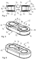
- FIG. 1 An elastic joint disk 10 is shown, which serves to connect two shaft sections (not shown) of a drive shaft of a motor vehicle.
- the joint disk 10 has a plurality of thread package support devices 12, which are partially encased by an elastomer body 14, and a plurality of bushings 16, which each connect two thread package support devices 12 to one another.
- the yarn package support device 12 has a first deflection section 18 and a second deflection section 20, which are connected to one another in one piece via a web 22.
- the thread package support device 12 is made in one piece by injection molding from a plastic, in particular a fiber-reinforced plastic.
- Each of the deflection sections 18, 20 comprises an arcuate thread guide area 19, two tangential thread guide areas 21, a through opening 24 for pressing in a section of a bush 16 and a bead section 26 to which the web 22 is connected. Furthermore, each of the deflection sections 18, 20 has two opposing collar sections 28a, 28b which project radially outward from the deflection sections 18, 20 and define a guide region 30 between them.
- the thread package support device 12 is wrapped with a thread 32 in order to produce a thread package 34, the thread package 34 being guided within the guide region 30 defined by the collar sections 28a, 28b.
- the two collar sections 28a, 28b thus prevent the thread package 34 from sliding down from the thread package support device 12.
- the thread package 34 has two opposing arcuate thread areas 36 and two tangential thread areas 38 connecting the arcuate thread areas 36 and running parallel to one another.
- the arcuate thread area 36 is guided around the arcuate thread guide area 19 and a section of one of the tangential thread areas 38 abuts one of the tangential thread guide areas 21.
- a distance a between the opposite collar sections 28a, 28b is continuously widening in the tangential thread guide regions 21.
- the two collar sections 28a, 28b form a funnel-shaped opening angle for the tangential thread region 38.
- the distance a between the collar sections 28a, 28b is constant. As a result, the free thread length in the arcuate thread region 36 is increased.
- the web 22 has a smaller axial extent than the two bead sections 26 and can be separated from the two bead sections 26, in particular punched out.
- the web 22 is cut off or punched out when the thread package support device 12 is partially encased by the elastomer body 14.
- Fig. 7 A thread package support device 12 with a separated web 22 is shown.
- the bead portions 26 have a support area 40 for supporting the thread package support device 12.
- the thread package support device 12 is introduced into a punching device (not shown) in such a way that the thread package support device 12 is supported on its support area 40.
- the two deflection sections 18, 20 can be moved relative to one another.
- the funnel-shaped opening angles make it possible to achieve high bending angles, in particular in the area of the tangential thread areas 38.
- the bead portions 26, when the web 22 is separated act as stops 42 during strong deflection movements. The deflection movement can be adjusted via the shape of the bead sections 26.
- a possible method for producing the joint disk 10 is explained below.
- six thread package support devices 12 are initially provided and pretreated, in particular coated.
- Each thread package support device 12 is then inserted separately into a winding machine, not shown.
- Each thread package support device 12 is then wrapped with a thread 32 in the winding machine to produce a thread package 34, as shown in FIG Fig. 5 is shown.
- the thread package support devices 12 together with the thread package 34 are then placed in a vulcanization mold and partially extrusion-coated with an elastomer material and then vulcanized to produce the elastomer body 14, as shown in FIG Fig. 6 is shown. Thereafter, the yarn package support devices 12, which are partially coated with the elastomer body 14, are cooled.
- the web 22 is then cut off, in particular punched out.
- the thread package support device 12 is inserted into a punching device, not shown, in such a way that the thread package support devices 12 are supported on their support areas 40.
- the thread package support devices are then positioned as shown in FIG Fig. 1 is shown, so that the through openings 24 of two superimposed thread package support devices 12 are aligned.
- the bushings 16 are pressed into the through openings 24 in order to connect the thread package support devices 12 to one another to form the joint disk 10.
- the previously described method for producing the rubber joint disk can also be modified in such a way that the yarn package support devices 12 wrapped with the yarn package 34 are first connected by means of the bushings 16 to form a joint disk base body, and then the joint disk base body is inserted into a vulcanization mold in order to to partially encase individual yarn package support devices 12 with the elastomer body 14. Finally, the webs 22 are then cut off, in particular punched out.
Landscapes
- Engineering & Computer Science (AREA)
- General Engineering & Computer Science (AREA)
- Mechanical Engineering (AREA)
- Injection Moulding Of Plastics Or The Like (AREA)
- Packaging Of Annular Or Rod-Shaped Articles, Wearing Apparel, Cassettes, Or The Like (AREA)
- Storing, Repeated Paying-Out, And Re-Storing Of Elongated Articles (AREA)
- Coils Of Transformers For General Uses (AREA)
- Absorbent Articles And Supports Therefor (AREA)
- Springs (AREA)
Claims (13)
- Dispositif de support de faisceau de fils (12) pour supporter un faisceau de fils (34) bobiné avec un fil (32) pour un joint élastique à déformation (10) pour relier deux sections d'arbre, dans lequel le faisceau de fils (34) présente deux zones de fil arquées (36) opposées et deux zones de fil tangentielles (38) s'étendant parallèlement et reliant l'une à l'autre les zones de fil arquées (36), dans lequel le dispositif de support de faisceau de fils (12) présente une première section de renvoi (18) et une deuxième section de renvoi (20), autour desquelles respectivement une zone de fil arquée (36) du faisceau de fils (34) est guidée, dans lequel les deux sections de renvoi (18, 20) sont reliées l'une à l'autre d'un seul tenant via une passerelle (22) et caractérisé en ce que les sections de renvoi (18, 20) et la passerelle (22) sont fabriquées d'un seul tenant dans le procédé de moulage par injection.
- Dispositif de support de faisceau de fils (12) selon la revendication 1 caractérisé en ce que chacune des sections de renvoi (18, 20) présente au moins une zone d'appui (40) pour l'appui du dispositif de support de faisceau de fils (12) pour la séparation de la passerelle (22).
- Dispositif de support de faisceau de fils (12) selon l'une quelconque des revendications précédentes, caractérisé en ce que chacune des sections de renvoi (18, 20) présente deux sections de col (28a, 28b) opposées, qui reçoivent entre elles et supportent axialement le faisceau de fils (34).
- Dispositif de support de faisceau de fils (12) selon la revendication 3 caractérisé en ce qu'une distance s'élargit en continu entre les sections de col (28a, 28b) opposées dans la zone d'un guide-fil tangentiel.
- Dispositif de support de faisceau de fils selon l'une quelconque des revendications précédentes, caractérisé en ce que chaque section de renvoi (18, 20) présente une zone guide-fil arquée (19), autour de laquelle une zone de fil arquée (36) est guidée, et deux zones guide-fil tangentielles (21), dans lequel chacune des zones guide-fil tangentielles (21) guide une section d'une zone de fil tangentielle (38).
- Dispositif de support de faisceau de fils (12) selon l'une quelconque des revendications précédentes, caractérisé en ce que chacune des sections de renvoi (18, 20) présente une ouverture de passage (24) pour presser une douille (16) et une section de talon (26) pour attacher la passerelle (22).
- Dispositif de support de faisceau de fils (12) selon l'une quelconque des revendications précédentes, caractérisé par un corps élastomère (14), qui enveloppe partiellement le dispositif de support de faisceau de fils (12).
- Dispositif de support de faisceau de fils (12) selon l'une quelconque des revendications précédentes, caractérisé en ce que les deux sections de renvoi (18, 20) et la passerelle (22) sont fabriquées en un plastique, en particulier un plastique renforcé de fibres.
- Joint élastique à déformation (10) pour relier deux sections d'arbre présentant une pluralité de dispositifs de support de faisceau de fils (12) selon l'une quelconque des revendications 1 à 9, une pluralité de faisceaux de fils (34) et une pluralité de douilles (16), dans lequel respectivement un faisceau de fils (34) s'enroule autour d'un dispositif de support de faisceau de fils (12), dans lequel chaque dispositif de support de faisceau de fils (12) enroulé avec un faisceau de fils (34) est enveloppé au moins en partie par un corps élastomère (14), et dans lequel respectivement une douille (16) relie l'un à l'autre deux dispositifs de support de faisceau de fils (12).
- Procédé de fabrication d'un joint élastique à déformation (10) pour relier deux sections d'arbre, qui comprend les étapes de procédé suivantes :a. mise à disposition d'une pluralité de dispositifs de support de faisceau de fils (12), dans lequel chaque dispositif de support de faisceau de fils (12) présente deux sections de renvoi (18, 20) et une passerelle (22) reliant l'une à l'autre d'un seul tenant les deux sections de renvoi (18, 20), dans lequel les sections de renvoi (18, 20) et la passerelle (22) sont fabriquées d'un seul tenant dans le procédé de moulage par injection, et dans lequel chaque section de renvoi (18, 20) présente une ouverture de passage (24) pour presser une douille (16) ;b. bobinage de chacun des dispositifs de support de faisceau de fils (12) avec un fil (32) pour générer un faisceau de fils (34) sur chacun des dispositifs de support de faisceau de fils (12) ;c. enveloppement partiel de chacun des dispositifs de support de faisceau de fils (12) avec un corps élastomère (14) ; etd. liaison des dispositifs de support de faisceau de fils (12) enveloppés partiellement avec un corps élastomère (14) au moyen d'une pluralité de douilles (16) en un joint à déformation (10), par le fait que respectivement une douille (16) est pressée dans les ouvertures de passage (24) de deux dispositifs de support de faisceau de fils (12).
- Procédé de fabrication d'un joint élastique à déformation (10) pour relier deux sections d'arbre, qui comprend les étapes de procédé suivantes :a. mise à disposition d'une pluralité de dispositifs de support de faisceau de fils (12), dans lequel chaque dispositif de support de faisceau de fils (12) présente deux sections de renvoi (18, 20) et une passerelle (22) reliant l'une à l'autre d'un seul tenant les deux sections de renvoi (18, 20), dans lequel les sections de renvoi (18, 20) et la passerelle (22) sont fabriquées d'un seul tenant dans le procédé de moulage par injection, et dans lequel chaque section de renvoi (18, 20) présente une ouverture de passage (24) pour presser une douille (16) ;b. bobinage de chacun des dispositifs de support de faisceau de fils (12) avec un fil (32) pour générer un faisceau de fils (34) sur chacun des dispositifs de support de faisceau de fils (12) ;c. liaison des dispositifs de support de faisceau de fils (12) au moyen d'une pluralité de douilles (16) en un corps de base de joint à déformation, par le fait que respectivement une douille (16) est pressée dans les ouvertures de passage (24) de deux dispositifs de support de faisceau de fils (12) ; etd. enveloppement partiel de chacun des dispositifs de support de faisceau de fils (12) avec un corps élastomère (14).
- Procédé selon la revendication 10 ou 11 caractérisé en ce que la passerelle (22) est séparée des sections de renvoi (18, 20), après que chacun des dispositifs de support de faisceau de fils (12) a été enveloppé partiellement avec un corps élastomère (14).
- Procédé selon l'une quelconque des revendications 10 à 12 caractérisé en ce que avant l'étape b) les dispositifs de support de faisceau de fils (12) sont revêtus.
Priority Applications (1)
| Application Number | Priority Date | Filing Date | Title |
|---|---|---|---|
| PL17781112T PL3529510T3 (pl) | 2016-10-24 | 2017-10-09 | Przyrząd do podtrzymywania pakietu kordu, elastyczna tarcza przegubowa oraz sposób wytwarzania elastycznej tarczy przegubowej |
Applications Claiming Priority (2)
| Application Number | Priority Date | Filing Date | Title |
|---|---|---|---|
| DE102016120252.5A DE102016120252B4 (de) | 2016-10-24 | 2016-10-24 | Fadenpaketabstützungsvorrichtung, elastische Gelenkscheibe sowie ein Verfahren zur Herstellung einer elastischen Gelenkscheibe |
| PCT/EP2017/075708 WO2018077606A1 (fr) | 2016-10-24 | 2017-10-09 | Dispositif de support de faisceau de fils de joint élastique à déformation ainsi que procédé pour fabriquer un joint élastique à déformation |
Publications (2)
| Publication Number | Publication Date |
|---|---|
| EP3529510A1 EP3529510A1 (fr) | 2019-08-28 |
| EP3529510B1 true EP3529510B1 (fr) | 2020-07-22 |
Family
ID=60043210
Family Applications (1)
| Application Number | Title | Priority Date | Filing Date |
|---|---|---|---|
| EP17781112.2A Active EP3529510B1 (fr) | 2016-10-24 | 2017-10-09 | Dispositif de support de faisceau de fils de joint élastique à déformation ainsi que procédé pour fabriquer un joint élastique à déformation |
Country Status (8)
| Country | Link |
|---|---|
| US (1) | US11378136B2 (fr) |
| EP (1) | EP3529510B1 (fr) |
| KR (1) | KR102488439B1 (fr) |
| CN (1) | CN109952445B (fr) |
| DE (1) | DE102016120252B4 (fr) |
| ES (1) | ES2826829T3 (fr) |
| PL (1) | PL3529510T3 (fr) |
| WO (1) | WO2018077606A1 (fr) |
Families Citing this family (1)
| Publication number | Priority date | Publication date | Assignee | Title |
|---|---|---|---|---|
| DE102016120252B4 (de) | 2016-10-24 | 2020-07-02 | Vibracoustic Gmbh | Fadenpaketabstützungsvorrichtung, elastische Gelenkscheibe sowie ein Verfahren zur Herstellung einer elastischen Gelenkscheibe |
Family Cites Families (17)
| Publication number | Priority date | Publication date | Assignee | Title |
|---|---|---|---|---|
| US1712730A (en) * | 1927-02-24 | 1929-05-14 | Bert G Goble | Pumping-jack chain |
| US2192946A (en) * | 1938-01-28 | 1940-03-12 | Harold G Towner | Grommet |
| CH321633A (de) * | 1953-02-24 | 1957-05-15 | Eduard Erhardt Fa | Elastische Wellengelenkscheibe mit Seillaschen |
| JPS51143158A (en) | 1975-06-04 | 1976-12-09 | Toyota Motor Corp | Flexible coupling for power transmission |
| JPH03239817A (ja) * | 1990-02-15 | 1991-10-25 | Bridgestone Corp | 可撓軸継手 |
| DE19720857C2 (de) * | 1997-05-17 | 2001-09-27 | Daimler Chrysler Ag | Wellengelenk |
| JP4123337B2 (ja) | 2002-01-25 | 2008-07-23 | Nok株式会社 | フレキシブルカップリング |
| DE10359281B3 (de) | 2003-12-17 | 2005-08-25 | SGF Süddeutsche Gelenkscheibenfabrik GmbH & Co KG | Drehgelenkkupplung zum gegenseitigen Verbinden zweier Wellenenden, insbesondere im Antriebsstrang eines Kraftfahrzeugs |
| JP2006029450A (ja) | 2004-07-15 | 2006-02-02 | Toyo Tire & Rubber Co Ltd | 弾性継手 |
| DE102005031641B3 (de) | 2005-07-06 | 2006-09-07 | SGF Süddeutsche Gelenkscheibenfabrik GmbH & Co KG | Nachgiebige Kupplung zum gegenseitigen Verbinden zweier Drehkörper mit gegeneinander geneigten Achsen |
| DE102008047596A1 (de) | 2008-09-17 | 2010-03-25 | SGF SüDDEUTSCHE GELENKSCHEIBENFABRIK GMBH & CO. KG | Elastischer Gelenkkörper |
| DE202011108594U1 (de) | 2011-12-02 | 2012-01-16 | SGF SüDDEUTSCHE GELENKSCHEIBENFABRIK GMBH & CO. KG | Elastischer Gelenkkörper |
| DE102011121472A1 (de) | 2011-12-17 | 2013-06-20 | FlexCon Germany GmbH | Elastische Drehverbindungselement, insbesondere elastische Torsionskupplung oder elastische Gelenkscheibe |
| DE102012001139B4 (de) | 2012-01-21 | 2019-09-19 | FlexCon Germany GmbH | Verfahren zur Herstellung eines elastischen Drehverbindungselements sowie elastisches Drehverbindungselement, insbesondere elastische Torsionskupplung oder elastische Gelenkscheibe |
| DE102012001972A1 (de) | 2012-02-02 | 2013-08-08 | FlexCon Germany GmbH | Lasche für eine Torsionskupplung |
| DE102014003572B4 (de) * | 2014-03-10 | 2025-04-17 | Süddeutsche Gelenkscheibenfabrik GmbH & Co. KG | Elastischer Gelenkkörper |
| DE102016120252B4 (de) | 2016-10-24 | 2020-07-02 | Vibracoustic Gmbh | Fadenpaketabstützungsvorrichtung, elastische Gelenkscheibe sowie ein Verfahren zur Herstellung einer elastischen Gelenkscheibe |
-
2016
- 2016-10-24 DE DE102016120252.5A patent/DE102016120252B4/de not_active Expired - Fee Related
-
2017
- 2017-10-09 US US16/344,073 patent/US11378136B2/en active Active
- 2017-10-09 PL PL17781112T patent/PL3529510T3/pl unknown
- 2017-10-09 EP EP17781112.2A patent/EP3529510B1/fr active Active
- 2017-10-09 ES ES17781112T patent/ES2826829T3/es active Active
- 2017-10-09 CN CN201780065583.8A patent/CN109952445B/zh active Active
- 2017-10-09 KR KR1020197011744A patent/KR102488439B1/ko active Active
- 2017-10-09 WO PCT/EP2017/075708 patent/WO2018077606A1/fr not_active Ceased
Non-Patent Citations (1)
| Title |
|---|
| None * |
Also Published As
| Publication number | Publication date |
|---|---|
| CN109952445B (zh) | 2022-01-28 |
| DE102016120252A1 (de) | 2018-04-26 |
| US20190257364A1 (en) | 2019-08-22 |
| CN109952445A (zh) | 2019-06-28 |
| ES2826829T3 (es) | 2021-05-19 |
| EP3529510A1 (fr) | 2019-08-28 |
| WO2018077606A1 (fr) | 2018-05-03 |
| KR102488439B1 (ko) | 2023-01-13 |
| PL3529510T3 (pl) | 2021-05-31 |
| KR20190075926A (ko) | 2019-07-01 |
| US11378136B2 (en) | 2022-07-05 |
| DE102016120252B4 (de) | 2020-07-02 |
Similar Documents
| Publication | Publication Date | Title |
|---|---|---|
| EP2334942B1 (fr) | Articulation élastique | |
| EP2132026B1 (fr) | Procédé de fabrication de renfort d'orifice pour une pièce en composite plastique et fibres, et pièce en composite plastique et fibres | |
| EP1015782B1 (fr) | Element articule elastique | |
| DE60118729T2 (de) | Riemen mit querverstärkung für stufenloses, regelbares getriebe | |
| DE1964090A1 (de) | Endloser Treibriemen,Vorrichtung und Verfahren zu seiner Herstellung | |
| DE29618513U1 (de) | Halter für rohrförmige Bauteile | |
| EP2600018B1 (fr) | Corps d'articulation élastique | |
| EP4056864B1 (fr) | Palier à douille | |
| EP2818594B1 (fr) | Câble en acier et son procédé de fabrication | |
| EP0315805B1 (fr) | Support pour moteur, transmission ou éléments similaires d'un véhicule automobile | |
| AT521959B1 (de) | Zahnrad | |
| DE112016001135B4 (de) | Gleitsystem für ein Umschlingungsgetriebe und Verwendung einer Gleitschiene für ein Umschlingungsmittel | |
| EP3529510B1 (fr) | Dispositif de support de faisceau de fils de joint élastique à déformation ainsi que procédé pour fabriquer un joint élastique à déformation | |
| EP2990689B1 (fr) | Poulie à courroie et dispositif de transmission par courroie doté d'une telle poulie à courroie | |
| DE102010024865B4 (de) | Kunststoff-Kettenglied, Verfahren zur Herstellung eines Kunststoff-Kettengliedes, Endloskette mit zumindest einem Kunststoff-Kettenglied und Endloskette mit einer Mehrzahl von Kunststoff-Kettengliedern | |
| EP2076688B1 (fr) | Procédé de calibrage d'un ressort en élastomère d'un palier | |
| EP3615355B1 (fr) | Bras de suspension quatre points et procédé de fabrication d'un bras de suspension sur quatre points | |
| DE102018117472B4 (de) | Faserverbundbauteil für den Einsatz im Kraftfahrzeugbereich sowie Verfahren zur Herstellung eines derartigen Faserverbundbauteils | |
| DE4204973A1 (de) | Verfahren zum herstellen einer gelenkscheibe sowie eine gelenkscheibe zum verbinden von wellenflanschen | |
| EP1724495A1 (fr) | Transmission à courroie crantée et procédé de fabrication d'un poulie pour transmission à courroie crantée | |
| DE102020114005B4 (de) | Verfahren zur Herstellung mehrerer elastomerer Buchsenlager mit Zwischenhülse | |
| DE102024001040A1 (de) | Fügetechnik an verdeckten Bauteilregionen | |
| DE102022104347A1 (de) | Elastischer Körper | |
| DE102004035712B4 (de) | Baugruppe mit Gasgenerator, Verfahren zur Herstellung der Baugruppe und Umformwerkzeug zur Verwendung in dem Verfahren | |
| DE102022129678A1 (de) | Wälzlager |
Legal Events
| Date | Code | Title | Description |
|---|---|---|---|
| STAA | Information on the status of an ep patent application or granted ep patent |
Free format text: STATUS: UNKNOWN |
|
| STAA | Information on the status of an ep patent application or granted ep patent |
Free format text: STATUS: THE INTERNATIONAL PUBLICATION HAS BEEN MADE |
|
| PUAI | Public reference made under article 153(3) epc to a published international application that has entered the european phase |
Free format text: ORIGINAL CODE: 0009012 |
|
| STAA | Information on the status of an ep patent application or granted ep patent |
Free format text: STATUS: REQUEST FOR EXAMINATION WAS MADE |
|
| 17P | Request for examination filed |
Effective date: 20190521 |
|
| AK | Designated contracting states |
Kind code of ref document: A1 Designated state(s): AL AT BE BG CH CY CZ DE DK EE ES FI FR GB GR HR HU IE IS IT LI LT LU LV MC MK MT NL NO PL PT RO RS SE SI SK SM TR |
|
| AX | Request for extension of the european patent |
Extension state: BA ME |
|
| STAA | Information on the status of an ep patent application or granted ep patent |
Free format text: STATUS: EXAMINATION IS IN PROGRESS |
|
| DAV | Request for validation of the european patent (deleted) | ||
| DAX | Request for extension of the european patent (deleted) | ||
| 17Q | First examination report despatched |
Effective date: 20200206 |
|
| GRAP | Despatch of communication of intention to grant a patent |
Free format text: ORIGINAL CODE: EPIDOSNIGR1 |
|
| STAA | Information on the status of an ep patent application or granted ep patent |
Free format text: STATUS: GRANT OF PATENT IS INTENDED |
|
| INTG | Intention to grant announced |
Effective date: 20200414 |
|
| GRAS | Grant fee paid |
Free format text: ORIGINAL CODE: EPIDOSNIGR3 |
|
| GRAA | (expected) grant |
Free format text: ORIGINAL CODE: 0009210 |
|
| STAA | Information on the status of an ep patent application or granted ep patent |
Free format text: STATUS: THE PATENT HAS BEEN GRANTED |
|
| AK | Designated contracting states |
Kind code of ref document: B1 Designated state(s): AL AT BE BG CH CY CZ DE DK EE ES FI FR GB GR HR HU IE IS IT LI LT LU LV MC MK MT NL NO PL PT RO RS SE SI SK SM TR |
|
| REG | Reference to a national code |
Ref country code: GB Ref legal event code: FG4D Free format text: NOT ENGLISH |
|
| REG | Reference to a national code |
Ref country code: CH Ref legal event code: EP |
|
| REG | Reference to a national code |
Ref country code: DE Ref legal event code: R096 Ref document number: 502017006353 Country of ref document: DE |
|
| REG | Reference to a national code |
Ref country code: AT Ref legal event code: REF Ref document number: 1293673 Country of ref document: AT Kind code of ref document: T Effective date: 20200815 |
|
| REG | Reference to a national code |
Ref country code: IE Ref legal event code: FG4D Free format text: LANGUAGE OF EP DOCUMENT: GERMAN |
|
| REG | Reference to a national code |
Ref country code: DE Ref legal event code: R081 Ref document number: 502017006353 Country of ref document: DE Owner name: VIBRACOUSTIC AG, DE Free format text: FORMER OWNER: VIBRACOUSTIC GMBH, 64293 DARMSTADT, DE Ref country code: DE Ref legal event code: R081 Ref document number: 502017006353 Country of ref document: DE Owner name: VIBRACOUSTIC SE, DE Free format text: FORMER OWNER: VIBRACOUSTIC GMBH, 64293 DARMSTADT, DE |
|
| RAP2 | Party data changed (patent owner data changed or rights of a patent transferred) |
Owner name: VIBRACOUSTIC AG |
|
| REG | Reference to a national code |
Ref country code: LT Ref legal event code: MG4D |
|
| REG | Reference to a national code |
Ref country code: SK Ref legal event code: T3 Ref document number: E 35685 Country of ref document: SK |
|
| PG25 | Lapsed in a contracting state [announced via postgrant information from national office to epo] |
Ref country code: FI Free format text: LAPSE BECAUSE OF FAILURE TO SUBMIT A TRANSLATION OF THE DESCRIPTION OR TO PAY THE FEE WITHIN THE PRESCRIBED TIME-LIMIT Effective date: 20200722 Ref country code: SE Free format text: LAPSE BECAUSE OF FAILURE TO SUBMIT A TRANSLATION OF THE DESCRIPTION OR TO PAY THE FEE WITHIN THE PRESCRIBED TIME-LIMIT Effective date: 20200722 Ref country code: BG Free format text: LAPSE BECAUSE OF FAILURE TO SUBMIT A TRANSLATION OF THE DESCRIPTION OR TO PAY THE FEE WITHIN THE PRESCRIBED TIME-LIMIT Effective date: 20201022 Ref country code: HR Free format text: LAPSE BECAUSE OF FAILURE TO SUBMIT A TRANSLATION OF THE DESCRIPTION OR TO PAY THE FEE WITHIN THE PRESCRIBED TIME-LIMIT Effective date: 20200722 Ref country code: PT Free format text: LAPSE BECAUSE OF FAILURE TO SUBMIT A TRANSLATION OF THE DESCRIPTION OR TO PAY THE FEE WITHIN THE PRESCRIBED TIME-LIMIT Effective date: 20201123 Ref country code: LT Free format text: LAPSE BECAUSE OF FAILURE TO SUBMIT A TRANSLATION OF THE DESCRIPTION OR TO PAY THE FEE WITHIN THE PRESCRIBED TIME-LIMIT Effective date: 20200722 Ref country code: NO Free format text: LAPSE BECAUSE OF FAILURE TO SUBMIT A TRANSLATION OF THE DESCRIPTION OR TO PAY THE FEE WITHIN THE PRESCRIBED TIME-LIMIT Effective date: 20201022 Ref country code: GR Free format text: LAPSE BECAUSE OF FAILURE TO SUBMIT A TRANSLATION OF THE DESCRIPTION OR TO PAY THE FEE WITHIN THE PRESCRIBED TIME-LIMIT Effective date: 20201023 |
|
| PG25 | Lapsed in a contracting state [announced via postgrant information from national office to epo] |
Ref country code: RS Free format text: LAPSE BECAUSE OF FAILURE TO SUBMIT A TRANSLATION OF THE DESCRIPTION OR TO PAY THE FEE WITHIN THE PRESCRIBED TIME-LIMIT Effective date: 20200722 Ref country code: LV Free format text: LAPSE BECAUSE OF FAILURE TO SUBMIT A TRANSLATION OF THE DESCRIPTION OR TO PAY THE FEE WITHIN THE PRESCRIBED TIME-LIMIT Effective date: 20200722 Ref country code: IS Free format text: LAPSE BECAUSE OF FAILURE TO SUBMIT A TRANSLATION OF THE DESCRIPTION OR TO PAY THE FEE WITHIN THE PRESCRIBED TIME-LIMIT Effective date: 20201122 |
|
| PG25 | Lapsed in a contracting state [announced via postgrant information from national office to epo] |
Ref country code: NL Free format text: LAPSE BECAUSE OF FAILURE TO SUBMIT A TRANSLATION OF THE DESCRIPTION OR TO PAY THE FEE WITHIN THE PRESCRIBED TIME-LIMIT Effective date: 20200722 |
|
| REG | Reference to a national code |
Ref country code: DE Ref legal event code: R097 Ref document number: 502017006353 Country of ref document: DE |
|
| PG25 | Lapsed in a contracting state [announced via postgrant information from national office to epo] |
Ref country code: EE Free format text: LAPSE BECAUSE OF FAILURE TO SUBMIT A TRANSLATION OF THE DESCRIPTION OR TO PAY THE FEE WITHIN THE PRESCRIBED TIME-LIMIT Effective date: 20200722 Ref country code: RO Free format text: LAPSE BECAUSE OF FAILURE TO SUBMIT A TRANSLATION OF THE DESCRIPTION OR TO PAY THE FEE WITHIN THE PRESCRIBED TIME-LIMIT Effective date: 20200722 Ref country code: CZ Free format text: LAPSE BECAUSE OF FAILURE TO SUBMIT A TRANSLATION OF THE DESCRIPTION OR TO PAY THE FEE WITHIN THE PRESCRIBED TIME-LIMIT Effective date: 20200722 Ref country code: DK Free format text: LAPSE BECAUSE OF FAILURE TO SUBMIT A TRANSLATION OF THE DESCRIPTION OR TO PAY THE FEE WITHIN THE PRESCRIBED TIME-LIMIT Effective date: 20200722 Ref country code: IT Free format text: LAPSE BECAUSE OF FAILURE TO SUBMIT A TRANSLATION OF THE DESCRIPTION OR TO PAY THE FEE WITHIN THE PRESCRIBED TIME-LIMIT Effective date: 20200722 Ref country code: SM Free format text: LAPSE BECAUSE OF FAILURE TO SUBMIT A TRANSLATION OF THE DESCRIPTION OR TO PAY THE FEE WITHIN THE PRESCRIBED TIME-LIMIT Effective date: 20200722 |
|
| REG | Reference to a national code |
Ref country code: ES Ref legal event code: FG2A Ref document number: 2826829 Country of ref document: ES Kind code of ref document: T3 Effective date: 20210519 |
|
| PLBE | No opposition filed within time limit |
Free format text: ORIGINAL CODE: 0009261 |
|
| STAA | Information on the status of an ep patent application or granted ep patent |
Free format text: STATUS: NO OPPOSITION FILED WITHIN TIME LIMIT |
|
| PG25 | Lapsed in a contracting state [announced via postgrant information from national office to epo] |
Ref country code: AL Free format text: LAPSE BECAUSE OF FAILURE TO SUBMIT A TRANSLATION OF THE DESCRIPTION OR TO PAY THE FEE WITHIN THE PRESCRIBED TIME-LIMIT Effective date: 20200722 |
|
| REG | Reference to a national code |
Ref country code: CH Ref legal event code: PL |
|
| 26N | No opposition filed |
Effective date: 20210423 |
|
| PG25 | Lapsed in a contracting state [announced via postgrant information from national office to epo] |
Ref country code: MC Free format text: LAPSE BECAUSE OF FAILURE TO SUBMIT A TRANSLATION OF THE DESCRIPTION OR TO PAY THE FEE WITHIN THE PRESCRIBED TIME-LIMIT Effective date: 20200722 Ref country code: LU Free format text: LAPSE BECAUSE OF NON-PAYMENT OF DUE FEES Effective date: 20201009 |
|
| REG | Reference to a national code |
Ref country code: DE Ref legal event code: R082 Ref document number: 502017006353 Country of ref document: DE Representative=s name: PATENTANWAELTE OLBRICHT, BUCHHOLD, KEULERTZ PA, DE Ref country code: DE Ref legal event code: R081 Ref document number: 502017006353 Country of ref document: DE Owner name: VIBRACOUSTIC SE, DE Free format text: FORMER OWNER: VIBRACOUSTIC AG, 64293 DARMSTADT, DE |
|
| REG | Reference to a national code |
Ref country code: BE Ref legal event code: MM Effective date: 20201031 |
|
| REG | Reference to a national code |
Ref country code: SK Ref legal event code: TC4A Ref document number: E 35685 Country of ref document: SK Owner name: VIBRACOUSTIC SE, DARMSTADT, DE Effective date: 20210730 |
|
| REG | Reference to a national code |
Ref country code: ES Ref legal event code: PC2A Owner name: VIBRACOUSTIC SE Effective date: 20210820 |
|
| PG25 | Lapsed in a contracting state [announced via postgrant information from national office to epo] |
Ref country code: BE Free format text: LAPSE BECAUSE OF NON-PAYMENT OF DUE FEES Effective date: 20201031 Ref country code: SI Free format text: LAPSE BECAUSE OF FAILURE TO SUBMIT A TRANSLATION OF THE DESCRIPTION OR TO PAY THE FEE WITHIN THE PRESCRIBED TIME-LIMIT Effective date: 20200722 Ref country code: LI Free format text: LAPSE BECAUSE OF NON-PAYMENT OF DUE FEES Effective date: 20201031 Ref country code: CH Free format text: LAPSE BECAUSE OF NON-PAYMENT OF DUE FEES Effective date: 20201031 |
|
| REG | Reference to a national code |
Ref country code: NL Ref legal event code: MP Effective date: 20200722 |
|
| PG25 | Lapsed in a contracting state [announced via postgrant information from national office to epo] |
Ref country code: IE Free format text: LAPSE BECAUSE OF NON-PAYMENT OF DUE FEES Effective date: 20201009 |
|
| PG25 | Lapsed in a contracting state [announced via postgrant information from national office to epo] |
Ref country code: TR Free format text: LAPSE BECAUSE OF FAILURE TO SUBMIT A TRANSLATION OF THE DESCRIPTION OR TO PAY THE FEE WITHIN THE PRESCRIBED TIME-LIMIT Effective date: 20200722 Ref country code: MT Free format text: LAPSE BECAUSE OF FAILURE TO SUBMIT A TRANSLATION OF THE DESCRIPTION OR TO PAY THE FEE WITHIN THE PRESCRIBED TIME-LIMIT Effective date: 20200722 Ref country code: CY Free format text: LAPSE BECAUSE OF FAILURE TO SUBMIT A TRANSLATION OF THE DESCRIPTION OR TO PAY THE FEE WITHIN THE PRESCRIBED TIME-LIMIT Effective date: 20200722 |
|
| GBPC | Gb: european patent ceased through non-payment of renewal fee |
Effective date: 20211009 |
|
| PG25 | Lapsed in a contracting state [announced via postgrant information from national office to epo] |
Ref country code: MK Free format text: LAPSE BECAUSE OF FAILURE TO SUBMIT A TRANSLATION OF THE DESCRIPTION OR TO PAY THE FEE WITHIN THE PRESCRIBED TIME-LIMIT Effective date: 20200722 |
|
| PG25 | Lapsed in a contracting state [announced via postgrant information from national office to epo] |
Ref country code: GB Free format text: LAPSE BECAUSE OF NON-PAYMENT OF DUE FEES Effective date: 20211009 |
|
| REG | Reference to a national code |
Ref country code: AT Ref legal event code: MM01 Ref document number: 1293673 Country of ref document: AT Kind code of ref document: T Effective date: 20221009 |
|
| PG25 | Lapsed in a contracting state [announced via postgrant information from national office to epo] |
Ref country code: AT Free format text: LAPSE BECAUSE OF NON-PAYMENT OF DUE FEES Effective date: 20221009 |
|
| PGFP | Annual fee paid to national office [announced via postgrant information from national office to epo] |
Ref country code: DE Payment date: 20251031 Year of fee payment: 9 |
|
| PGFP | Annual fee paid to national office [announced via postgrant information from national office to epo] |
Ref country code: FR Payment date: 20251030 Year of fee payment: 9 |
|
| PGFP | Annual fee paid to national office [announced via postgrant information from national office to epo] |
Ref country code: PL Payment date: 20251006 Year of fee payment: 9 |
|
| PGFP | Annual fee paid to national office [announced via postgrant information from national office to epo] |
Ref country code: SK Payment date: 20251006 Year of fee payment: 9 |
|
| PGFP | Annual fee paid to national office [announced via postgrant information from national office to epo] |
Ref country code: ES Payment date: 20251216 Year of fee payment: 9 |