EP3529512B1 - Kupplungsanordnung für ein hybridfahrzeug mit einer reibungskupplung und einer fliehkraftkupplung - Google Patents
Kupplungsanordnung für ein hybridfahrzeug mit einer reibungskupplung und einer fliehkraftkupplung Download PDFInfo
- Publication number
- EP3529512B1 EP3529512B1 EP17771415.1A EP17771415A EP3529512B1 EP 3529512 B1 EP3529512 B1 EP 3529512B1 EP 17771415 A EP17771415 A EP 17771415A EP 3529512 B1 EP3529512 B1 EP 3529512B1
- Authority
- EP
- European Patent Office
- Prior art keywords
- clutch
- friction
- arrangement according
- rotor
- output shaft
- Prior art date
- Legal status (The legal status is an assumption and is not a legal conclusion. Google has not performed a legal analysis and makes no representation as to the accuracy of the status listed.)
- Active
Links
Images


Classifications
-
- B—PERFORMING OPERATIONS; TRANSPORTING
- B60—VEHICLES IN GENERAL
- B60K—ARRANGEMENT OR MOUNTING OF PROPULSION UNITS OR OF TRANSMISSIONS IN VEHICLES; ARRANGEMENT OR MOUNTING OF PLURAL DIVERSE PRIME-MOVERS IN VEHICLES; AUXILIARY DRIVES FOR VEHICLES; INSTRUMENTATION OR DASHBOARDS FOR VEHICLES; ARRANGEMENTS IN CONNECTION WITH COOLING, AIR INTAKE, GAS EXHAUST OR FUEL SUPPLY OF PROPULSION UNITS IN VEHICLES
- B60K6/00—Arrangement or mounting of plural diverse prime-movers for mutual or common propulsion, e.g. hybrid propulsion systems comprising electric motors and internal combustion engines
- B60K6/20—Arrangement or mounting of plural diverse prime-movers for mutual or common propulsion, e.g. hybrid propulsion systems comprising electric motors and internal combustion engines the prime-movers consisting of electric motors and internal combustion engines, e.g. HEVs
- B60K6/22—Arrangement or mounting of plural diverse prime-movers for mutual or common propulsion, e.g. hybrid propulsion systems comprising electric motors and internal combustion engines the prime-movers consisting of electric motors and internal combustion engines, e.g. HEVs characterised by apparatus, components or means specially adapted for HEVs
- B60K6/38—Arrangement or mounting of plural diverse prime-movers for mutual or common propulsion, e.g. hybrid propulsion systems comprising electric motors and internal combustion engines the prime-movers consisting of electric motors and internal combustion engines, e.g. HEVs characterised by apparatus, components or means specially adapted for HEVs characterised by the driveline clutches
- B60K6/383—One-way clutches or freewheel devices
-
- B—PERFORMING OPERATIONS; TRANSPORTING
- B60—VEHICLES IN GENERAL
- B60K—ARRANGEMENT OR MOUNTING OF PROPULSION UNITS OR OF TRANSMISSIONS IN VEHICLES; ARRANGEMENT OR MOUNTING OF PLURAL DIVERSE PRIME-MOVERS IN VEHICLES; AUXILIARY DRIVES FOR VEHICLES; INSTRUMENTATION OR DASHBOARDS FOR VEHICLES; ARRANGEMENTS IN CONNECTION WITH COOLING, AIR INTAKE, GAS EXHAUST OR FUEL SUPPLY OF PROPULSION UNITS IN VEHICLES
- B60K6/00—Arrangement or mounting of plural diverse prime-movers for mutual or common propulsion, e.g. hybrid propulsion systems comprising electric motors and internal combustion engines
- B60K6/20—Arrangement or mounting of plural diverse prime-movers for mutual or common propulsion, e.g. hybrid propulsion systems comprising electric motors and internal combustion engines the prime-movers consisting of electric motors and internal combustion engines, e.g. HEVs
- B60K6/22—Arrangement or mounting of plural diverse prime-movers for mutual or common propulsion, e.g. hybrid propulsion systems comprising electric motors and internal combustion engines the prime-movers consisting of electric motors and internal combustion engines, e.g. HEVs characterised by apparatus, components or means specially adapted for HEVs
- B60K6/38—Arrangement or mounting of plural diverse prime-movers for mutual or common propulsion, e.g. hybrid propulsion systems comprising electric motors and internal combustion engines the prime-movers consisting of electric motors and internal combustion engines, e.g. HEVs characterised by apparatus, components or means specially adapted for HEVs characterised by the driveline clutches
- B60K6/387—Actuated clutches, i.e. clutches engaged or disengaged by electric, hydraulic or mechanical actuating means
-
- B—PERFORMING OPERATIONS; TRANSPORTING
- B60—VEHICLES IN GENERAL
- B60K—ARRANGEMENT OR MOUNTING OF PROPULSION UNITS OR OF TRANSMISSIONS IN VEHICLES; ARRANGEMENT OR MOUNTING OF PLURAL DIVERSE PRIME-MOVERS IN VEHICLES; AUXILIARY DRIVES FOR VEHICLES; INSTRUMENTATION OR DASHBOARDS FOR VEHICLES; ARRANGEMENTS IN CONNECTION WITH COOLING, AIR INTAKE, GAS EXHAUST OR FUEL SUPPLY OF PROPULSION UNITS IN VEHICLES
- B60K6/00—Arrangement or mounting of plural diverse prime-movers for mutual or common propulsion, e.g. hybrid propulsion systems comprising electric motors and internal combustion engines
- B60K6/20—Arrangement or mounting of plural diverse prime-movers for mutual or common propulsion, e.g. hybrid propulsion systems comprising electric motors and internal combustion engines the prime-movers consisting of electric motors and internal combustion engines, e.g. HEVs
- B60K6/42—Arrangement or mounting of plural diverse prime-movers for mutual or common propulsion, e.g. hybrid propulsion systems comprising electric motors and internal combustion engines the prime-movers consisting of electric motors and internal combustion engines, e.g. HEVs characterised by the architecture of the hybrid electric vehicle
-
- B—PERFORMING OPERATIONS; TRANSPORTING
- B60—VEHICLES IN GENERAL
- B60K—ARRANGEMENT OR MOUNTING OF PROPULSION UNITS OR OF TRANSMISSIONS IN VEHICLES; ARRANGEMENT OR MOUNTING OF PLURAL DIVERSE PRIME-MOVERS IN VEHICLES; AUXILIARY DRIVES FOR VEHICLES; INSTRUMENTATION OR DASHBOARDS FOR VEHICLES; ARRANGEMENTS IN CONNECTION WITH COOLING, AIR INTAKE, GAS EXHAUST OR FUEL SUPPLY OF PROPULSION UNITS IN VEHICLES
- B60K6/00—Arrangement or mounting of plural diverse prime-movers for mutual or common propulsion, e.g. hybrid propulsion systems comprising electric motors and internal combustion engines
- B60K6/20—Arrangement or mounting of plural diverse prime-movers for mutual or common propulsion, e.g. hybrid propulsion systems comprising electric motors and internal combustion engines the prime-movers consisting of electric motors and internal combustion engines, e.g. HEVs
- B60K6/42—Arrangement or mounting of plural diverse prime-movers for mutual or common propulsion, e.g. hybrid propulsion systems comprising electric motors and internal combustion engines the prime-movers consisting of electric motors and internal combustion engines, e.g. HEVs characterised by the architecture of the hybrid electric vehicle
- B60K6/48—Parallel type
-
- F—MECHANICAL ENGINEERING; LIGHTING; HEATING; WEAPONS; BLASTING
- F16—ENGINEERING ELEMENTS AND UNITS; GENERAL MEASURES FOR PRODUCING AND MAINTAINING EFFECTIVE FUNCTIONING OF MACHINES OR INSTALLATIONS; THERMAL INSULATION IN GENERAL
- F16D—COUPLINGS FOR TRANSMITTING ROTATION; CLUTCHES; BRAKES
- F16D21/00—Systems comprising a plurality of actuated clutches
-
- F—MECHANICAL ENGINEERING; LIGHTING; HEATING; WEAPONS; BLASTING
- F16—ENGINEERING ELEMENTS AND UNITS; GENERAL MEASURES FOR PRODUCING AND MAINTAINING EFFECTIVE FUNCTIONING OF MACHINES OR INSTALLATIONS; THERMAL INSULATION IN GENERAL
- F16D—COUPLINGS FOR TRANSMITTING ROTATION; CLUTCHES; BRAKES
- F16D27/00—Magnetically- or electrically- actuated clutches; Control or electric circuits therefor
- F16D27/10—Magnetically- or electrically- actuated clutches; Control or electric circuits therefor with an electromagnet not rotating with a clutching member, i.e. without collecting rings
- F16D27/108—Magnetically- or electrically- actuated clutches; Control or electric circuits therefor with an electromagnet not rotating with a clutching member, i.e. without collecting rings with axially movable clutching members
- F16D27/112—Magnetically- or electrically- actuated clutches; Control or electric circuits therefor with an electromagnet not rotating with a clutching member, i.e. without collecting rings with axially movable clutching members with flat friction surfaces, e.g. discs
-
- F—MECHANICAL ENGINEERING; LIGHTING; HEATING; WEAPONS; BLASTING
- F16—ENGINEERING ELEMENTS AND UNITS; GENERAL MEASURES FOR PRODUCING AND MAINTAINING EFFECTIVE FUNCTIONING OF MACHINES OR INSTALLATIONS; THERMAL INSULATION IN GENERAL
- F16D—COUPLINGS FOR TRANSMITTING ROTATION; CLUTCHES; BRAKES
- F16D43/00—Automatic clutches
- F16D43/02—Automatic clutches actuated entirely mechanically
- F16D43/04—Automatic clutches actuated entirely mechanically controlled by angular speed
- F16D43/14—Automatic clutches actuated entirely mechanically controlled by angular speed with centrifugal masses actuating the clutching members directly in a direction which has at least a radial component; with centrifugal masses themselves being the clutching members
- F16D43/16—Automatic clutches actuated entirely mechanically controlled by angular speed with centrifugal masses actuating the clutching members directly in a direction which has at least a radial component; with centrifugal masses themselves being the clutching members with clutching members having interengaging parts
-
- F—MECHANICAL ENGINEERING; LIGHTING; HEATING; WEAPONS; BLASTING
- F16—ENGINEERING ELEMENTS AND UNITS; GENERAL MEASURES FOR PRODUCING AND MAINTAINING EFFECTIVE FUNCTIONING OF MACHINES OR INSTALLATIONS; THERMAL INSULATION IN GENERAL
- F16D—COUPLINGS FOR TRANSMITTING ROTATION; CLUTCHES; BRAKES
- F16D47/00—Systems of clutches, or clutches and couplings, comprising devices of types grouped under at least two of the following sets of groups: F16D1/00 - F16D9/00, F16D11/00 - F16D23/00, F16D25/00 - F16D29/00, F16D31/00 - F16D39/00, F16D41/00 - F16D45/00
-
- B—PERFORMING OPERATIONS; TRANSPORTING
- B60—VEHICLES IN GENERAL
- B60K—ARRANGEMENT OR MOUNTING OF PROPULSION UNITS OR OF TRANSMISSIONS IN VEHICLES; ARRANGEMENT OR MOUNTING OF PLURAL DIVERSE PRIME-MOVERS IN VEHICLES; AUXILIARY DRIVES FOR VEHICLES; INSTRUMENTATION OR DASHBOARDS FOR VEHICLES; ARRANGEMENTS IN CONNECTION WITH COOLING, AIR INTAKE, GAS EXHAUST OR FUEL SUPPLY OF PROPULSION UNITS IN VEHICLES
- B60K6/00—Arrangement or mounting of plural diverse prime-movers for mutual or common propulsion, e.g. hybrid propulsion systems comprising electric motors and internal combustion engines
- B60K6/20—Arrangement or mounting of plural diverse prime-movers for mutual or common propulsion, e.g. hybrid propulsion systems comprising electric motors and internal combustion engines the prime-movers consisting of electric motors and internal combustion engines, e.g. HEVs
- B60K6/42—Arrangement or mounting of plural diverse prime-movers for mutual or common propulsion, e.g. hybrid propulsion systems comprising electric motors and internal combustion engines the prime-movers consisting of electric motors and internal combustion engines, e.g. HEVs characterised by the architecture of the hybrid electric vehicle
- B60K6/48—Parallel type
- B60K2006/4825—Electric machine connected or connectable to gearbox input shaft
-
- F—MECHANICAL ENGINEERING; LIGHTING; HEATING; WEAPONS; BLASTING
- F16—ENGINEERING ELEMENTS AND UNITS; GENERAL MEASURES FOR PRODUCING AND MAINTAINING EFFECTIVE FUNCTIONING OF MACHINES OR INSTALLATIONS; THERMAL INSULATION IN GENERAL
- F16D—COUPLINGS FOR TRANSMITTING ROTATION; CLUTCHES; BRAKES
- F16D43/00—Automatic clutches
- F16D43/02—Automatic clutches actuated entirely mechanically
- F16D43/04—Automatic clutches actuated entirely mechanically controlled by angular speed
- F16D43/14—Automatic clutches actuated entirely mechanically controlled by angular speed with centrifugal masses actuating the clutching members directly in a direction which has at least a radial component; with centrifugal masses themselves being the clutching members
- F16D2043/145—Automatic clutches actuated entirely mechanically controlled by angular speed with centrifugal masses actuating the clutching members directly in a direction which has at least a radial component; with centrifugal masses themselves being the clutching members the centrifugal masses being pivoting
-
- F—MECHANICAL ENGINEERING; LIGHTING; HEATING; WEAPONS; BLASTING
- F16—ENGINEERING ELEMENTS AND UNITS; GENERAL MEASURES FOR PRODUCING AND MAINTAINING EFFECTIVE FUNCTIONING OF MACHINES OR INSTALLATIONS; THERMAL INSULATION IN GENERAL
- F16D—COUPLINGS FOR TRANSMITTING ROTATION; CLUTCHES; BRAKES
- F16D23/00—Details of mechanically-actuated clutches not specific for one distinct type
- F16D23/02—Arrangements for synchronisation, also for power-operated clutches
- F16D23/04—Arrangements for synchronisation, also for power-operated clutches with an additional friction clutch
-
- F—MECHANICAL ENGINEERING; LIGHTING; HEATING; WEAPONS; BLASTING
- F16—ENGINEERING ELEMENTS AND UNITS; GENERAL MEASURES FOR PRODUCING AND MAINTAINING EFFECTIVE FUNCTIONING OF MACHINES OR INSTALLATIONS; THERMAL INSULATION IN GENERAL
- F16D—COUPLINGS FOR TRANSMITTING ROTATION; CLUTCHES; BRAKES
- F16D2300/00—Special features for couplings or clutches
- F16D2300/14—Clutches which are normally open, i.e. not engaged in released state
-
- Y—GENERAL TAGGING OF NEW TECHNOLOGICAL DEVELOPMENTS; GENERAL TAGGING OF CROSS-SECTIONAL TECHNOLOGIES SPANNING OVER SEVERAL SECTIONS OF THE IPC; TECHNICAL SUBJECTS COVERED BY FORMER USPC CROSS-REFERENCE ART COLLECTIONS [XRACs] AND DIGESTS
- Y02—TECHNOLOGIES OR APPLICATIONS FOR MITIGATION OR ADAPTATION AGAINST CLIMATE CHANGE
- Y02T—CLIMATE CHANGE MITIGATION TECHNOLOGIES RELATED TO TRANSPORTATION
- Y02T10/00—Road transport of goods or passengers
- Y02T10/60—Other road transportation technologies with climate change mitigation effect
- Y02T10/62—Hybrid vehicles
Definitions
- the present invention relates to a clutch arrangement for a hybrid vehicle according to the preamble of patent claim 1.
- a generic clutch arrangement with a form-locking clutch and a friction clutch arranged functionally parallel thereto is already based on FIG DE 10 2015 201 931 A1 and is arranged there between an internal combustion engine and an electrical machine in order, for example, to couple the internal combustion engine to the electrical machine by means of the friction clutch during electrical driving and to start the latter.
- the form-fit coupling can be closed by meshing a toothed arrangement in order to direct the drive torque of the internal combustion engine to the vehicle wheels.
- this arrangement can lead to an undesired premature closing of the form-fit coupling, namely before the friction clutch is completely closed, which can adversely affect driving comfort due to the design of the form-fit coupling.
- the present invention is based on the stated prior art, the task of presenting a generic clutch arrangement which reliably avoids the above-mentioned problem.
- the interlocking unit can advantageously have at least one displaceable first element, in particular a pawl with a first interlocking profile and a second element, in particular a ratchet wheel with a second interlocking profile, the first element being in a rotationally driving connection with the input shaft and the second element with the output shaft wherein the form-fit profiles can be brought into mutual engagement by exceeding the form-fit coupling speed by centrifugal force.
- the actuating means can be designed for electromagnetic actuation of the friction clutches.
- An electromagnet provided for this purpose can advantageously be designed as a ring magnet designed concentrically to the input or output shaft, which interacts with an axially displaceable magnet armature and with a displaceable coupling element of the friction clutch, as will be explained below.
- the friction unit can advantageously have an axially displaceable pressure plate, an abutment arrangement with a counter pressure plate and a friction disk arranged between these, the pressure plate and the counter pressure plate with the Input shaft or the output shaft and wherein the friction disk is in rotary driving connection with the other of the input shaft and output shaft.
- An arrangement that saves space, in particular axially, can be achieved by arranging the form-fit coupling and the friction coupling in a radially staggered manner with respect to one another and at least partially overlapping one another axially.
- the friction unit and the form-fit unit can be arranged radially staggered with respect to one another and at least partially overlap axially, the form-fit unit in particular being arranged radially inside the friction unit.
- the electrical machine can advantageously be designed as an internal rotor, the rotor being arranged radially inside the stator.
- the outer peripheral surface of the rotor can interact in a known manner with the stator via a radial air gap and the inner peripheral surface of the rotor can support or form the abutment arrangement of the friction clutch.
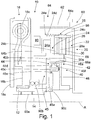
- Fig. 1 shows a clutch arrangement 10 for a hybrid vehicle, which initially comprises an input shaft 12 and an output shaft 14 arranged coaxially therewith, and a friction clutch 20 and a form-locking clutch 40, which are functionally arranged in parallel between the input shaft 12 and the output shaft 14.
- the clutch arrangement 10 is preceded by a torsion damper 16 in the form of a two-mass flywheel, which is provided with an input side 16a for connection to the crankshaft of an internal combustion engine.
- the input side 16a is connected to an output side 16b with the interposition of several energy stores 16c designed as helical compression springs, which is then in rotational driving with the input shaft 12 by means of a spline.
- the rotor 66 has a radially extending rotor arm 66a, wherein as in FIG Fig. 1 recognizable, the receiving space 68 is formed axially between the radial wall area 64b and the rotor arm 66a and axially closed on both sides.
- the pressure plate 26 and the counter pressure plate 28a are connected to the output shaft 14 via the rotor carrier 66a, and the friction disk 30 is in a rotationally driving connection with the input shaft 12.
- the abutment arrangement 28 with the counterpressure plate 28a of the friction clutch 20 is formed on an axially extending section of the rotor arm 66a on and non-rotatably with respect to the rotor 66.
- the pressure plate 26 is inserted axially displaceably within the rotor 66 and is firmly connected to a magnet armature 24b, also in the form of an annular disk, by means of several axially protruding tension bolts 24c distributed around the circumference, which are guided through corresponding recesses in the counter pressure plate 28a.
- the input shaft 12 is supported twice by means of a roller bearing 90b on the radial wall area 64b and the output shaft 14 is supported twice with respect to the input shaft 12 by means of the roller bearings 90a, 90c, the output shaft 14 being at least indirectly supported with the clutch arrangement 10 in a vehicle when it is installed connected to an input shaft of a gear change transmission and supported by this.
- the friction clutch 20 is relieved and can be deactivated, but this does not necessarily have to be done. This means that the frictional connection or the coupling can be maintained even when the form-fit coupling 20 is closed.
Landscapes
- Engineering & Computer Science (AREA)
- Mechanical Engineering (AREA)
- General Engineering & Computer Science (AREA)
- Chemical & Material Sciences (AREA)
- Combustion & Propulsion (AREA)
- Transportation (AREA)
- Physics & Mathematics (AREA)
- Electromagnetism (AREA)
- Hybrid Electric Vehicles (AREA)
Description
- Die vorliegende Erfindung bezieht sich auf eine Kupplungsanordnung für ein Hybridfahrzeug gemäß dem Oberbegriff von Patentanspruch 1.
- Eine gattungsgemäße Kupplungsanordnung mit einer Formschlusskupplung und einer dazu funktional parallel angeordneten Reibungskupplung geht bereits aus der
DE 10 2015 201 931 A1 hervor und ist dort zwischen einem Verbrennungsmotor und einer elektrischen Maschine angeordnet, um beispielsweise den Verbrennungsmotor bei elektrischem Fahrbetrieb mittels der Reibungskupplung an die elektrische Maschine anzukoppeln und diesen zu starten. Sobald eine Synchronisation von Kurbelwelle und Rotorwelle vorliegt, kann die Formschlusskupplung durch Ineinandergreifen einer Verzahnungsanordnung geschlossen werden, um darüber das Antriebsmoment des Verbrennungsmotors an die Fahrzeugräder zu leiten. Zur Betätigung von Formschlusskupplung und Reibungskupplung ist ein gemeinsames Betätigungsmittel in Form eines hydraulischen oder elektromotorischen Aktors vorgesehen, wobei bei dessen Aktivierung eine stufenweise Kupplungsbetätigung erfolgt und zuerst die Elemente der Reibeinheit und danach bei erfolgter Synchronisierung der beteiligten Wellen die Elemente der Formschlusseinheit miteinander in Eingriff gebracht werden. - Infolge der stufenweisen wegabhängigen Betätigung kann es bei dieser Anordnung zu einem unerwünschten vorzeitigen Schließen der Formschlusskupplung kommen und zwar bevor die Reibungskupplung vollständig geschlossen ist, was wegen der konstruktiven Ausgestaltung der Formschlusskupplung den Fahrkomfort ungünstig beeinflussen kann.
- Eine Freilauftrennkupplung mit einer Reibungskupplung und einer parallel angeordneten Fliehkraftkupplung ist aus
DE 10 2011 080 454 A1 bekannt. - Der vorliegenden Erfindung liegt von dem genannten Stand der Technik die Aufgabe zugrunde, eine gattungsgemäße Kupplungsanordnung darzustellen, welche das vorstehend genannte Problem sicher vermeidet.
- Diese Aufgabe wird durch eine Kupplungsanordnung mit den Merkmalen des Patentanspruchs 1 gelöst.
- Vorteilhafte Ausgestaltungen und Weiterbildungen der Erfindung sind den abhängigen Ansprüchen sowie der nachfolgenden Figurenbeschreibung entnehmbar.
- Es wird demnach eine Kupplungsanordnung für ein Hybridfahrzeug vorgeschlagen, welche eine Eingangswelle und eine dazu koaxial angeordnete Ausgangswelle und weiter eine Reibungskupplung und eine Formschlusskupplung umfasst, welche funktional parallel zwischen der Eingangswelle und der Ausgangswelle angeordnet sind und wobei die Reibungskupplung eine durch Betätigungsmittel betätigbare Reibeinheit und die Formschlusskupplung eine durch zugeordnete Betätigungsmittel betätigbare Formschlusseinheit aufweist.
- Gemäß der Erfindung zeichnet sich die Kupplungsanordnung dadurch aus, dass die Formschlusskupplung als Fliehkraftkupplung zur drehzahlabhängigen selbsttägigen Betätigung ausgebildet ist, wobei die zugeordneten Betätigungsmittel mit der Eingangswelle oder der Ausgangswelle wirkverbunden sind.
- Durch diese Ausgestaltung ergibt sich der grundlegende Vorteil, dass die Formschlusskupplung erst dann selbsttätig vom geöffneten in den geschlossenen Zustand übergeht, wenn eine vorgegebene Drehzahl überschritten wird. Beispielweise kann das Schließen der Reibungskupplung bei einer ersten vorgebbaren Drehzahl (Reibungskoppeldrehzahl) einer drehenden Welle erfolgen, welche die Ausgangs- oder die Eingangswelle sein kann, wobei die jeweils anzukoppelnde andere Welle durch den Koppelvorgang auf das Drehzahlniveau der drehenden Welle angehoben werden soll. Mit anderen Worten soll im Ergebnis eine Drehzahlgleichheit von Eingangswelle und Ausgangswelle vorliegen. Das Schließen der Fliehkraftkupplung kann dabei bereits in einem Zustand vorgenommen werden, bei welchem noch eine gewisse, insbesondere eine geringe Drehzahldifferenz in Form einer kleineren Drehzahl der anzukoppelnden Welle an die drehende Welle vorhanden ist und wobei eine vergleichsweise geringe Relativbewegung von Eingangswelle und Ausgangswelle auftritt. Wenn in diesem Zustand eine festgelegte Fliehkraftkoppeldrehzahl der Fliehkraftkupplung erreicht wird, so können nun im Verlauf der Relativdrehbewegung bei Einnahme einer drehstellungsabhängigen Formschlusskoppelstellung die zu koppelnde Elemente selbsttätig in eine drehfeste formschlüssige Mitnahme gelangen. Auf diese Weise kann durch die Reibungskupplung solange eine zunehmende Drehzahlangleichung von Eingangs- und Ausgangswelle erfolgen, wobei vor Erreichung einer Synchrondrehzahl der Wellen die Formschlusskupplung geschlossen wird.
- Die Reibungskupplung kann grundsätzlich als normal-offen oder als normalgeschlossen Typ ausgeführt werden, während die Formschlusskupplung als normal-offen Typ ausgeführt ist und erst bei Erreichen der Fliehkraftkoppeldrehzahl von einer der beteiligten Wellen selbsttätig geschlossen wird.
- Die Formschlusseinheit kann mit Vorteil zumindest ein verlagerbares erstes Element, insbesondere eine Klinke mit einem ersten Formschlussprofil und ein zweites Element, insbesondere ein Klinkenrad mit einem zweiten Formschlussprofil aufweisen, wobei das erste Element mit der Eingangswelle und das zweite Element mit der Ausgangswelle in Drehmitnahmeverbindung steht und wobei die Formschlussprofile durch das Überschreiten der Formschlusskoppeldrehzahl durch Fliehkraftwirkung gegenseitig in Eingriff bringbar sind.
- Gemäß einer vorteilhaften Ausgestaltung der Kupplungsanordnung können die Betätigungsmittel zur elektromagnetischen Betätigung der Reibungskupplungen ausgebildet sein. Ein zu diesem Zweck vorgesehener Elektromagnet kann mir Vorteil als ein konzentrisch zu der Eingangs- bzw. Ausgangswelle ausgebildeter Ringmagnet ausgebildet sein, der mit einem axial verlagerbaren Magnetanker und mit einem verlagerbaren Kupplungselement von der Reibungskupplung zusammenwirkt, wie dieses nachstehend erläutert wird.
- Mit Vorteil kann die Reibeinheit eine axial verlagerbare Anpressplatte, eine Widerlageranordnung mit einer Gegenanpressplatte und eine zwischen diesen angeordnete Reibscheibe aufweisen, wobei die Anpressplatte und die Gegenanpressplatte mit der Eingangswelle oder der Ausgangswelle und wobei die Reibscheibe mit der jeweils anderen von Eingangswelle und Ausgangswelle in Drehmitnahmeverbindung steht.
- Eine insbesondere axial bauraumsparende Anordnung kann erzielt werden, indem die Formschlusskupplung und die Reibungskupplung radial gestaffelt zueinander angeordnet werden und sich gegenseitig zumindest teilweise axial überlappen. Insbesondere können dabei die Reibeinheit und die Formschlusseinheit radial gestaffelt zueinander angeordnet sein und sich zumindest teilweise axial überlappen, wobei insbesondere die Formschlusseinheit radial innerhalb der Reibeinheit angeordnet ist.
- Gemäß einer Weiterbildung der Erfindung kann bei der Kupplungsanordnung eine elektrische Maschine mit einem Rotor und mit einem Stator vorgesehen sein, wobei der Rotor mit der Ausgangswelle in Drehmitnahmeverbindung steht und wobei die elektrische Maschine einen zentralen Aufnahmeraum aufweist, in welchem die Reibungskupplung und die Formschlusskupplung vollständig oder zumindest teilweise aufgenommen sind.
- Davon ausgehend kann mit Vorteil die Widerlageranordnung der Reibungskupplung am Rotor ausgebildet sein. Mit anderen Worten kann die elektrische Maschine einen Teil der Reibungskupplung ausbilden.
- Mit noch weiterem Vorteil kann der Stator einen Statorträger mit einem den Aufnahmeraum begrenzenden Radialwandbereich umfassen oder der Aufnahmeraum kann benachbart zu einem Radialwandbereich einer weiteren Komponente angeordnet sein, an welchem die Betätigungsmittel der Reibungskupplung und der Formschlusskupplung festgelegt werden können.
- Eine räumlich gegenüber weiteren Antriebsstrangkomponenten abgegrenzte Kupplungsanordnung kann erzielt werden, indem der Rotor einen sich radial erstreckenden Rotorträger aufweist, wobei der Aufnahmeraum von Reibungskupplung und Formschlusskupplung und von deren Betätigungseinheiten axial zwischen dem besagten Radialwandbereich und dem Rotorträger ausgebildet ist.
- Mit weiterem Vorteil kann die Reibungskupplung eine elektronische Ansteuereinheit zur Ansteuerung der Betätigungsmittel aufweisen, wobei die Ansteuereinheit an dem Radialwandbereich, insbesondere innerhalb des Aufnahmeraums angeordnet ist.
- Gemäß einem vorteilhaften Lagerungskonzept der Kupplungsanordnung kann vorgesehen sein, die Eingangswelle an dem Radialwandbereich und die Ausgangswelle zweifach zur Eingangswelle zu lagern. Im Weiteren kann die Ausgangswelle an einem Eingangsbereich einer im Drehmomentfluss nachfolgenden Komponente eines vorliegenden Antriebstrangs gelagert sein. Beispielsweise kann die Ausgangswelle zumindest mittelbar mit einer Eingangswelle eines Gangwechselgetriebes verbunden und durch diese gelagert sein.
- Für eine bauliche Integration einer elektrischen Maschine in die Kupplungsanordnung kann vorteilhaft die elektrische Maschine ist als Innenläufer ausgebildet sein, wobei der Rotor radial innerhalb des Stators angeordnet ist. Dabei kann die Außenumfangsfläche des Rotors in bekannter Weise über einen radialen Luftspalt mit dem Stator zusammenwirken und die Innenumfangsfläche des Rotors kann die Widerlageranordnung der Reibungskupplung tragen oder ausbilden.
- Insgesamt kann die Kupplungsanordnung als ein räumlich kompaktes und separates Modul zum Einbau in einen Fahrzeugantriebsstrang ausgebildet sein, wobei sich deren einzelne Elemente gegenseitig abstützen und eine feste Lagezuordnung aufweisen.
- Es zeigen:
- Fig. 1
- eine Schnittdarstellung einer Kupplungsanordnung mit einer normal-offenen Reibungskupplung, einer als Fliehkraftkupplung ausgebildeten Formschlusskupplung und einer elektrischen Maschine;
- Fig. 2
- eine Radialschnittdarstellung der Fliehkraftkupplung in einem geöffneten Zustand;
- Fig. 3
- eine Radialschnittdarstellung der Fliehkraftkupplung in einem geschlossenen Zustand.
-
Fig. 1 zeigt eine Kupplungsanordnung 10 für ein Hybridfahrzeug, welche zunächst eine Eingangswelle 12 und eine dazu koaxial angeordnete Ausgangswelle 14 und eine Reibungskupplung 20 und eine Formschlusskupplung 40 umfasst, welche funktional parallel zwischen der Eingangswelle 12 und der Ausgangswelle 14 angeordnet sind. Der Kupplungsanordnung 10 ist vorliegend ein Torsionsdämpfer 16 in Form eines Zweimassenschwungrades vorgeschaltet, welches mit einer Eingangsseite 16a zur Verbindung mit der Kurbelwelle eines Verbrennungsmotors vorgesehen ist. Die Eingangsseite 16a ist unter Zwischenschaltung von mehreren als Schraubendruckfedern ausgeführten Energiespeichern 16c mit einer Ausgangsseite 16b verbunden, welche im Weiteren mittels einer Steckverzahnung mit der Eingangswelle 12 in Drehmitnahme steht. - Die Kupplungsanordnung 10 umfasst weiter eine elektrische Maschine 60 mit einem Stator 62 und mit einem Rotor 66, welcher mit der Ausgangswelle 14 verbunden ist und in Drehmitnahmeverbindung steht. Innerhalb der elektrischen Maschine 60 ist ein zentraler Aufnahmeraum 68 vorgesehen, in welchem die Reibungskupplung 20 und die Formschlusskupplung 40 vollständig aufgenommen sind. Die elektrische Maschine 60 ist hier als Innenläufer ausgebildet, wobei der Rotor 66 radial innerhalb des Stators 62 angeordnet und drehbar um eine Achse A ist und wobei der Aufnahmeraum 68 zur Aufnahme der Kupplungen 40, 60 im Wesentlichen innerhalb des Rotors 66 vorliegt.
- Der Stator 62 umfasst einen Statorträger 64 mit einem sich axial erstreckenden Zylinderwandbereich 64a zur Anordnung einer elektromagnetischen Statorkomponente und weiter einen den Aufnahmeraum 68 einseitig begrenzenden Radialwandbereich 64b. Eine Drehmomentabstützung des Statorträgers 64 kann beispielsweise an einem hier nicht zeichnerisch nicht dargestellten Getriebegehäuse oder einer anderen zu den Wellen 12, 14 und dem Rotor 66 drehentkoppelten Komponente erfolgen.
- Der Rotor 66 weist einen sich radial erstreckenden Rotorträger 66a auf, wobei wie in
Fig. 1 erkennbar, der Aufnahmeraum 68 axial zwischen dem Radialwandbereich 64b und dem Rotorträger 66a ausgebildet und axial beidseitig abgeschlossen ist. - Die Reibungskupplung 20 weist eine Reibeinheit 22 auf, welche durch ein zur elektromagnetischen Betätigung ausgebildetes Betätigungsmittel 24 betätigbar ist. Die Betätigungsmittel 24 umfassen einen ringförmigen um die Drehachse A ausgebildeten Elektromagnet 24a dessen Magnetfeld bei einer Strombeaufschlagung im Wesentlichen in axialer Richtung aus einer U-förmig ausgeführten Gehäuseschale austreten kann. Der Elektromagnet 24a ist am Radialwandbereich 64b des Statorträgers 64 festgelegt und dort in einen dafür geschaffenen Aufnahmebereich eingesetzt.
- Die Reibungskupplung 20 und die Formschlusskupplung 40 sind in dem mit
Fig. 1 erläuterten Ausführungsbeispiel beide vom normal-offen Typ. - Die Reibeinheit 22 der trockenlaufenden Reibungskupplung 20 umfasst eine axial verlagerbare Anpressplatte 26, eine Widerlageranordnung 28 mit einer ringscheibenförmigen Gegenanpressplatte 28a und eine zwischen diesen angeordnete Reibscheibe 30 mit einem Trägerbereich 30a.
- Die Anpressplatte 26 und die Gegenanpressplatte 28a stehen über den Rotorträger 66a mit der Ausgangswelle 14 und die Reibscheibe 30 steht mit der Eingangswelle 12 in Drehmitnahmeverbindung. Die Widerlageranordnung 28 mit der Gegenanpressplatte 28a der Reibungskupplung 20 ist an einem sich axial erstreckenden Abschnitt des Rotorträgers 66a am und drehfest zum Rotor 66 ausgebildet. Zur Ermöglichung eines Reibschlusses ist die Anpressplatte 26 einerseits innerhalb des Rotors 66 axial verlagerbar eingesetzt und andererseits mittels mehrerer am Umfang verteilter und axial abstehender Zugbolzen 24c, welche durch entsprechende Ausnehmungen der Gegenanpressplatte 28a geführt sind mit einem gleichfalls ringscheibenförmigen Magnetanker 24b fest verbunden. Dadurch kann bei einer Aktivierung des Elektromagneten 24a eine Zugkraft auf den Magnetanker 24b und die Anpressplatte 26 übertragen und die Reibscheibe 30 reibschlüssig zwischen der Anpressplatte 26 und der Gegenanpressplatte 28a zum Schließen der Reibungskupplung 20 eingeklemmt werden. Zur Ermöglichung einer Rückstellbewegung der Anpressplatte 26 ist ein als Druckfeder ausgebildetes Rückstellelement 24d zwischen dem Magnetanker 24b und einer Abstützung 24e vorgesehen.
- Die Formschlusskupplung 40 umfasst ein mit der Eingangswelle 12 verbundenes Trägerrad 45 mit einem scheibenförmigen Abschnitt 45a und mit einem sich an dessen Außenumfang anschließenden hohlzylindrischen Abschnitt 45b. An dem scheibenförmigen Abschnitt 45a sind mittels Zapfen 45c mehrere am Umfang verteilte Klinken 45d gelagert, welche sich unter dem Einfluss einer wirkenden Fliehkraft entgegen der Wirkung von als Druckfedern ausgebildeten Rückstelleelementen 45e verschwenken können und dabei mit einem an diesen ausgebildeten ersten Formschlussprofil 45f nach radial außen verlagern können, wie dieses besonders anhand der
Fig. 2 ,3 erkennbar ist. Das erste Formschlussprofil 45f kann somit jeweils arretierend in ein dazu korrespondierendes zweites Formschlussprofil 46a eingreifen, welches als Ausnehmungen an einer Innenumfangsfläche 46b eines als Hohlrad ausgebildeten Klinkenrades 46 vorhanden ist. Durch das Ineinandergreifen der Formschlussprofile 45f, 46a wird in einer Drehrichtung des Trägerrades 45, hier linksdrehend, eine Drehmitnahme des Klinkenrades 46 ermöglicht, während in der Gegendrehrichtung die Klinken 45d infolge der nicht-formschlüssigen Formgebung des Klinkenrades 45 abgewiesen werden und nicht einrasten können. - Die Klinken 45d mit dem ersten Formschlussprofil 45f und das Klinkenrad 46 mit dem zweiten Formschlussprofil 46a bilden gemeinsam eine Formschlusseinheit 42, welche durch die hier zudem als Betätigungsmittel 44 fungierenden und vorliegend mit der Eingangswelle 12 wirkverbundenen und verschwenkbaren Klinken 45d fliehkraftbedingt betätigt werden. Der hohlzylindrische Abschnitt 45b ist axial endseitig mit dem Trägerbereich 30a der Reibscheibe 30 und das Klinkenrad 45 ist vorliegend mittels einer Steckverzahnung oder einer Verschweißung drehfest mit der Ausgangswelle 14 verbunden.
- Der Eingriff der Formschlussprofile 45f, 46a und die gegenseitige Drehmitnahme der Wellen 12, 14 kann bei Unterschreiten einer Formschlusskoppeldrehzahl in Verbindung mit einer zumindest kurzzeitigen gegenseitigen Drehmomententlastung aufgehoben werden, wobei die Klinken 45d durch die Wirkung der Rückstellelemente 45e wieder zurück in deren in
Fig. 2 dargestellte Ausgangslage gelangen. - In
Fig. 1 ist erkennbar, dass die Formschlusskupplung 40 und die Reibungskupplung 20 radial gestaffelt zueinander angeordnet sind und sich gegenseitig zumindest teilweise axial überlappen. Insbesondere sind die Reibeinheit 22 und die Formschlusseinheit 42 radial gestaffelt zueinander angeordnet und können sich zumindest teilweise axial überlappen, wobei insbesondere die Formschlusseinheit 42 radial innerhalb der Reibeinheit 22 angeordnet ist. - Die Reibungskupplung 20 weist weiterhin eine elektronische Ansteuereinheit 80 zur Ansteuerung der Betätigungsmittel 24, insbesondere des Elektromagnete 24a auf. Die Ansteuereinheit 80 ist räumlich unmittelbar benachbart zu dem Elektromagnet 24a an dem Radialwandbereich 64b, insbesondere innerhalb des Aufnahmeraums 68 angeordnet ist.
- Es ist ferner erkennbar, dass die Eingangswelle 12 mittels eines Wälzlagers 90b an dem Radialwandbereich 64b und die Ausgangswelle 14 mittels der Wälzlager 90a, 90c zweifach zur Eingangswelle 12 gelagert ist, wobei die Ausgangswelle 14 im eingebauten Zustand der Kupplungsanordnung 10 in einem Fahrzeug zumindest mittelbar mit einer Eingangswelle eines Gangwechselgetriebes verbunden und durch diese gelagert sein.
- Bei der erläuterten Kupplungsanordnung 10 wird zum Starten eines mit der Eingangswelle 12 gekoppelten Verbrennungsmotors eines Hybridfahrzeuges bei elektromotorischen Fahrbetrieb zunächst die Reibungskupplung 20 geschlossen und dabei der Verbrennungsmotor unter Hochschleppen von dessen Kurbelwelle angeworfen. Kurz vor Erreichen einer Synchrondrehzahl von Eingangs- und Ausgangswelle und damit der Einnahme einer drehfesten Koppelung von Eingangs- 12 und Ausgangswelle 14 wird bei Erreichen einer vorgegebenen Formschlusskoppeldrehzahl die Formschlusskupplung 20 selbsttätig geschlossen.
- Da die Formschlusskupplung 40 zur vollständigen Übertragung des Antriebsmomentes des Verbrennungsmotors ausgelegt ist, ist die Reibungskupplung 20 dadurch entlastet und kann deaktiviert werden, was jedoch nicht zwangsweise erfolgen muss. Das heißt, dass der Reibschluss bzw. die Koppelung auch bei geschlossener Formschlusskupplung 20 aufrechterhalten werden kann.
-
10 Kupplungsanordnung 12 Eingangswelle 44c Rückstellelement 14 Ausgangswelle 45 Trägerrad 16 Torsionsdämpfer 45a scheibenförmiger Abschnitt 16a Eingangsseite 45b hohlzylindrischer Abschnitt 16b Ausgangsseite 45c Zapfen 16c Energiespeicher 45d Klinke 20 Reibungskupplung 45e Rückstellelement 22 Reibeinheit 45f erstes Formschlussprofil 24 Betätigungsmittel 46 Klinkenrad 24a Elektromagnet 46a zweites Formschlussprofil 24b Magnetanker 46b Innenumfangsfläche 24c Zugbolzen 60 elektrische Maschine 24d Rückstellelement 62 Stator 24e Abstützung 64 Statorträger 26 Anpressplatte 64a Zylinderwandbereich 28 Widerlageranordnung 64b Radialwandbereich 28a Gegenanpressplatte 66 Rotor 30 Reibscheibe 66a Rotorträger 30a Trägerbereich 68 Aufnahmeraum 40 Formschlusskupplung 80 Ansteuereinheit 42 Formschlusseinheit 90a-c Lager 44 Betätigungsmittel A Drehachse
Claims (12)
- Kupplungsanordnung (10) für ein Hybridfahrzeug, umfassend- eine Eingangswelle (12) und eine dazu koaxial angeordnete Ausgangswelle (14),- eine Reibungskupplung (20) und eine Formschlusskupplung (40), welche funktional parallel zwischen der Eingangswelle (12) und der Ausgangswelle (14) angeordnet sind, wobei- die Reibungskupplung (20) eine durch zugeordnete Betätigungsmittel (24) betätigbare Reibeinheit (22) aufweist, und wobei- die Formschlusskupplung (40) eine durch zugeordnete Betätigungsmittel (44) betätigbare Formschlusseinheit (42) aufweist,dadurch gekennzeichnet, dass die Formschlusskupplung (40) als Fliehkraftkupplung zur drehzahlabhängigen selbsttägigen Betätigung ausgebildet ist, wobei die zugeordneten Betätigungsmittel (44) mit der Eingangswelle (12) oder der Ausgangswelle (14) wirkverbunden sind.
- Kupplungsanordnung nach einem der Ansprüche 1-3, dadurch gekennzeichnet, dass die Formschlusseinheit (42) ein verlagerbares erstes Element (45d) mit einem ersten Formschlussprofil (45f) und ein zweites Element (46) mit einem zweiten Formschlussprofil (46a) aufweist, wobei das erste Element (45d) mit der Eingangswelle (12) und das zweite Element (46) mit der Ausgangswelle (14) in Drehmitnahmeverbindung steht und wobei die Formschlussprofile (45f, 46a) durch das Überschreiten einer vorgebbaren Fliehkraftkoppelrehzahl durch Fliehkraftwirkung gegenseitig in Eingriff bringbar sind.
- Kupplungsanordnung nach Anspruch 1, dadurch gekennzeichnet, dass das Betätigungsmittel (24) der Reibungskupplung (20) zur elektromagnetischen Betätigung ausgebildet ist.
- Kupplungsanordnung nach einem Anspruch 1 oder 2, dadurch gekennzeichnet, dass die Reibeinheit (22) eine axial verlagerbare Anpressplatte (26), eine Widerlageranordnung (28) mit einer Gegenanpressplatte (28a) und eine zwischen diesen angeordnete Reibscheibe (30) aufweist, wobei die Anpressplatte (26) und die Gegenanpressplatte (28a) mit der Eingangswelle (12) oder der Ausgangswelle (14) und wobei die Reibscheibe (30) mit der jeweils anderen von Eingangswelle (12) und Ausgangswelle (14) in Drehmitnahmeverbindung steht.
- Kupplungsanordnung nach einem der Ansprüche 1-4, dadurch gekennzeichnet, dass die Formschlusskupplung (40) und die Reibungskupplung (20) radial gestaffelt zueinander angeordnet sind und sich gegenseitig zumindest teilweise axial überlappen.
- Kupplungsanordnung nach einem der Ansprüche 1-5, dadurch gekennzeichnet, dass eine elektrische Maschine (60) mit einem Rotor (66) und mit einem Stator (62) vorgesehen ist, wobei der Rotor (66) mit der Ausgangswelle (14) in Drehmitnahmeverbindung steht und wobei die elektrische Maschine (60) einen zentralen Aufnahmeraum (68) aufweist, in welchem die Reibungskupplung (20) und die Formschlusskupplung (40) vollständig oder zumindest teilweise aufgenommen sind.
- Kupplungsanordnung nach Anspruch 6, dadurch gekennzeichnet, dass die Widerlageranordnung (28) der Reibungskupplung (20) am Rotor (66) ausgebildet ist.
- Kupplungsanordnung nach Anspruch 6 oder 7, dadurch gekennzeichnet, dass der Stator (62) einen Statorträger (64) mit einem den Aufnahmeraum (68) begrenzenden Radialwandbereich (64b) umfasst oder dass der Aufnahmeraum (68) benachbart zu einem Radialwandbereich (64b) einer weiteren Komponente angeordnet ist, an welchem die Betätigungsmittel (24, 44) der Reibungskupplung (20) und der Formschlusskupplung (40) festgelegt sind.
- Kupplungsanordnung nach einem der Ansprüche 6-8, dadurch gekennzeichnet, dass der Rotor (66) einen sich radial erstreckenden Rotorträger (66a) aufweist, wobei der Aufnahmeraum (68) axial zwischen dem Radialwandbereich (64b) und dem Rotorträger (68a) ausgebildet ist.
- Kupplungsanordnung nach Anspruch 9, dadurch gekennzeichnet, dass Reibungskupplung (20) eine Ansteuereinheit (80) zur Ansteuerung der Betätigungsmittel (24) aufweist, wobei die Ansteuereinheit (80) an dem Radialwandbereich (64b), insbesondere innerhalb des Aufnahmeraums (68) angeordnet ist.
- Kupplungsanordnung nach einem der Ansprüche 8-10, dadurch gekennzeichnet, dass die Eingangswelle (12) an dem Radialwandbereich (64b) und die Ausgangswelle (14) zweifach zur Eingangswelle (12) gelagert ist.
- Kupplungsanordnung nach einem der Ansprüche 8-11, dadurch gekennzeichnet, die elektrische Maschine (60) ist als Innenläufer ausgebildet ist, wobei der Rotor (66) radial innerhalb des Stators (62) angeordnet ist.
Applications Claiming Priority (2)
| Application Number | Priority Date | Filing Date | Title |
|---|---|---|---|
| DE102016220711.3A DE102016220711A1 (de) | 2016-10-21 | 2016-10-21 | Kupplungsanordnung für ein Hybridfahrzeug mit einer Reibungskupplung und einer Fliehkraftkupplung |
| PCT/EP2017/073536 WO2018072944A1 (de) | 2016-10-21 | 2017-09-19 | Kupplungsanordnung für ein hybridfahrzeug mit einer reibungskupplung und einer fliehkraftkupplung |
Publications (2)
| Publication Number | Publication Date |
|---|---|
| EP3529512A1 EP3529512A1 (de) | 2019-08-28 |
| EP3529512B1 true EP3529512B1 (de) | 2020-08-19 |
Family
ID=59923432
Family Applications (1)
| Application Number | Title | Priority Date | Filing Date |
|---|---|---|---|
| EP17771415.1A Active EP3529512B1 (de) | 2016-10-21 | 2017-09-19 | Kupplungsanordnung für ein hybridfahrzeug mit einer reibungskupplung und einer fliehkraftkupplung |
Country Status (3)
| Country | Link |
|---|---|
| EP (1) | EP3529512B1 (de) |
| DE (1) | DE102016220711A1 (de) |
| WO (1) | WO2018072944A1 (de) |
Cited By (1)
| Publication number | Priority date | Publication date | Assignee | Title |
|---|---|---|---|---|
| US12466251B2 (en) | 2023-03-19 | 2025-11-11 | Customachinery Inc. | Transmission system for a hybrid drive unit |
Families Citing this family (2)
| Publication number | Priority date | Publication date | Assignee | Title |
|---|---|---|---|---|
| DE102020213838A1 (de) * | 2020-11-04 | 2022-05-05 | Zf Friedrichshafen Ag | Drehmomentübertragungsanordnung |
| DE102021118703A1 (de) | 2021-07-20 | 2023-01-26 | Schaeffler Technologies AG & Co. KG | Hybridmodul |
Citations (1)
| Publication number | Priority date | Publication date | Assignee | Title |
|---|---|---|---|---|
| DE102011080454A1 (de) * | 2011-08-04 | 2013-02-07 | Schaeffler Technologies AG & Co. KG | Freilauftrennkupplung mit einer Freilaufanordnung |
Family Cites Families (8)
| Publication number | Priority date | Publication date | Assignee | Title |
|---|---|---|---|---|
| US4733577A (en) * | 1984-11-06 | 1988-03-29 | Zahnradfabrik Friedrichshafen Ag | Electromagnetically actuated locking clutch for differential gears of motor vehicles |
| DE19503501C2 (de) * | 1995-02-03 | 1997-12-18 | Mannesmann Sachs Ag | Hybridantrieb mit serieller Anordnung seiner einzelnen Komponenten für ein Kraftfahrzeug |
| DE10025853A1 (de) * | 1999-06-02 | 2001-04-19 | Luk Lamellen & Kupplungsbau | Antriebsstrang und Verfahren zu dessen Betrieb |
| US7846051B2 (en) * | 2007-05-11 | 2010-12-07 | Gm Global Technology Operations, Inc. | Hybrid powertrain with an engine input clutch and method of control |
| DE102009045562A1 (de) * | 2009-10-12 | 2011-04-14 | Zf Friedrichshafen Ag | Kupplungsanordnung und Ankopplungsverfahren für ein Fahrzeug mit einer ersten und einer zweiten Antriebsvorrichtung |
| DE202011104776U1 (de) * | 2011-08-24 | 2012-11-27 | Isatec Gmbh | Generator-/Antriebsanordnung |
| DE102012221881A1 (de) * | 2011-12-09 | 2013-06-13 | Schaeffler Technologies AG & Co. KG | Parallelschaltgetriebe |
| DE102015201931A1 (de) | 2015-02-04 | 2016-08-04 | Bayerische Motoren Werke Aktiengesellschaft | Antriebssystem für ein Hybridfahrzeug |
-
2016
- 2016-10-21 DE DE102016220711.3A patent/DE102016220711A1/de not_active Withdrawn
-
2017
- 2017-09-19 EP EP17771415.1A patent/EP3529512B1/de active Active
- 2017-09-19 WO PCT/EP2017/073536 patent/WO2018072944A1/de not_active Ceased
Patent Citations (1)
| Publication number | Priority date | Publication date | Assignee | Title |
|---|---|---|---|---|
| DE102011080454A1 (de) * | 2011-08-04 | 2013-02-07 | Schaeffler Technologies AG & Co. KG | Freilauftrennkupplung mit einer Freilaufanordnung |
Cited By (1)
| Publication number | Priority date | Publication date | Assignee | Title |
|---|---|---|---|---|
| US12466251B2 (en) | 2023-03-19 | 2025-11-11 | Customachinery Inc. | Transmission system for a hybrid drive unit |
Also Published As
| Publication number | Publication date |
|---|---|
| DE102016220711A1 (de) | 2018-04-26 |
| WO2018072944A1 (de) | 2018-04-26 |
| EP3529512A1 (de) | 2019-08-28 |
Similar Documents
| Publication | Publication Date | Title |
|---|---|---|
| EP3448706B1 (de) | Hybridmodul und antriebsanordnung für ein kraftfahrzeug | |
| EP2655113B1 (de) | Hybridmodul für einen triebstrang eines fahrzeuges | |
| DE102009045727A1 (de) | Antriebseinheit für ein Hybridfahrzeug | |
| DE102013221643B4 (de) | Rotor einer elektrischen Maschine | |
| DE102011078110A1 (de) | Antriebselement eines Getriebes | |
| DE102015215447A1 (de) | Antriebsmodul für einen Antriebsstrang eines Hybridfahrzeugs | |
| WO2018113818A1 (de) | Hybridmodul und antriebsanordnung für ein kraftfahrzeug | |
| DE10005996A1 (de) | Drehmomentübertragungseinheit | |
| DE102015203571A1 (de) | Kupplungsvorrichtung | |
| DE102014202621A1 (de) | Lageranordnung eines Getriebes | |
| DE102015217164A1 (de) | Baugruppe mit einer Reibeinrichtung | |
| EP3529512B1 (de) | Kupplungsanordnung für ein hybridfahrzeug mit einer reibungskupplung und einer fliehkraftkupplung | |
| DE102014206985A1 (de) | Kupplungsaktor | |
| DE102015215153A1 (de) | Hybridmodul für Handschalter- und automatisiertes Handschaltgetriebe eines Hybridfahrzeuges | |
| DE102012206680A1 (de) | Hybridmodul für einen Triebstrang eines Fahrzeuges | |
| EP2448092A2 (de) | Antriebseinheit mit einer Elektromaschine und einer Kupplung | |
| DE102013225355A1 (de) | Betätigungsvorrichtung für eine Kupplung, Kupplung, elektrisches Fahrmodul und Verfahren zur Montage einer Kupplung | |
| DE102016215268A1 (de) | Hybridantriebssystem für ein Transportmittel, insbesondere für ein Kraftfahrzeug | |
| DE102009016164A1 (de) | Kupplung und Verfahren zur Kopplung eines Generators mit einer Kurbelwelle | |
| DE102015100906B4 (de) | Synchronisiereinrichtung, Kupplungsanordnung und Antriebsanordnung | |
| EP3983250A1 (de) | Hybridkupplungsmodul sowie antriebsstrang für ein fahrzeug mit dem hybridkupplungsmodul | |
| EP3529511B1 (de) | Kupplungsanordnung für ein hybridfahrzeug | |
| DE102015226679A1 (de) | Getriebe für ein Kraftfahrzeug | |
| DE10033424A1 (de) | Elektrische Maschine | |
| DE19954372B4 (de) | Antriebsstrang |
Legal Events
| Date | Code | Title | Description |
|---|---|---|---|
| STAA | Information on the status of an ep patent application or granted ep patent |
Free format text: STATUS: UNKNOWN |
|
| STAA | Information on the status of an ep patent application or granted ep patent |
Free format text: STATUS: THE INTERNATIONAL PUBLICATION HAS BEEN MADE |
|
| PUAI | Public reference made under article 153(3) epc to a published international application that has entered the european phase |
Free format text: ORIGINAL CODE: 0009012 |
|
| STAA | Information on the status of an ep patent application or granted ep patent |
Free format text: STATUS: REQUEST FOR EXAMINATION WAS MADE |
|
| 17P | Request for examination filed |
Effective date: 20190405 |
|
| AK | Designated contracting states |
Kind code of ref document: A1 Designated state(s): AL AT BE BG CH CY CZ DE DK EE ES FI FR GB GR HR HU IE IS IT LI LT LU LV MC MK MT NL NO PL PT RO RS SE SI SK SM TR |
|
| AX | Request for extension of the european patent |
Extension state: BA ME |
|
| DAV | Request for validation of the european patent (deleted) | ||
| DAX | Request for extension of the european patent (deleted) | ||
| REG | Reference to a national code |
Ref country code: DE Ref legal event code: R079 Ref document number: 502017006845 Country of ref document: DE Free format text: PREVIOUS MAIN CLASS: F16D0023040000 Ipc: F16D0043140000 |
|
| GRAP | Despatch of communication of intention to grant a patent |
Free format text: ORIGINAL CODE: EPIDOSNIGR1 |
|
| STAA | Information on the status of an ep patent application or granted ep patent |
Free format text: STATUS: GRANT OF PATENT IS INTENDED |
|
| RIC1 | Information provided on ipc code assigned before grant |
Ipc: F16D 11/16 20060101ALI20200217BHEP Ipc: F16D 43/14 20060101AFI20200217BHEP |
|
| INTG | Intention to grant announced |
Effective date: 20200311 |
|
| RIN1 | Information on inventor provided before grant (corrected) |
Inventor name: VIERNEKES, GERALD Inventor name: LUDSTECK, SVEN Inventor name: DEPPERT, REINHARD |
|
| GRAS | Grant fee paid |
Free format text: ORIGINAL CODE: EPIDOSNIGR3 |
|
| GRAA | (expected) grant |
Free format text: ORIGINAL CODE: 0009210 |
|
| STAA | Information on the status of an ep patent application or granted ep patent |
Free format text: STATUS: THE PATENT HAS BEEN GRANTED |
|
| AK | Designated contracting states |
Kind code of ref document: B1 Designated state(s): AL AT BE BG CH CY CZ DE DK EE ES FI FR GB GR HR HU IE IS IT LI LT LU LV MC MK MT NL NO PL PT RO RS SE SI SK SM TR |
|
| REG | Reference to a national code |
Ref country code: CH Ref legal event code: EP |
|
| REG | Reference to a national code |
Ref country code: DE Ref legal event code: R096 Ref document number: 502017006845 Country of ref document: DE |
|
| REG | Reference to a national code |
Ref country code: AT Ref legal event code: REF Ref document number: 1304267 Country of ref document: AT Kind code of ref document: T Effective date: 20200915 |
|
| REG | Reference to a national code |
Ref country code: IE Ref legal event code: FG4D Free format text: LANGUAGE OF EP DOCUMENT: GERMAN |
|
| REG | Reference to a national code |
Ref country code: LT Ref legal event code: MG4D |
|
| REG | Reference to a national code |
Ref country code: NL Ref legal event code: MP Effective date: 20200819 |
|
| PG25 | Lapsed in a contracting state [announced via postgrant information from national office to epo] |
Ref country code: FI Free format text: LAPSE BECAUSE OF FAILURE TO SUBMIT A TRANSLATION OF THE DESCRIPTION OR TO PAY THE FEE WITHIN THE PRESCRIBED TIME-LIMIT Effective date: 20200819 Ref country code: GR Free format text: LAPSE BECAUSE OF FAILURE TO SUBMIT A TRANSLATION OF THE DESCRIPTION OR TO PAY THE FEE WITHIN THE PRESCRIBED TIME-LIMIT Effective date: 20201120 Ref country code: PT Free format text: LAPSE BECAUSE OF FAILURE TO SUBMIT A TRANSLATION OF THE DESCRIPTION OR TO PAY THE FEE WITHIN THE PRESCRIBED TIME-LIMIT Effective date: 20201221 Ref country code: HR Free format text: LAPSE BECAUSE OF FAILURE TO SUBMIT A TRANSLATION OF THE DESCRIPTION OR TO PAY THE FEE WITHIN THE PRESCRIBED TIME-LIMIT Effective date: 20200819 Ref country code: SE Free format text: LAPSE BECAUSE OF FAILURE TO SUBMIT A TRANSLATION OF THE DESCRIPTION OR TO PAY THE FEE WITHIN THE PRESCRIBED TIME-LIMIT Effective date: 20200819 Ref country code: NO Free format text: LAPSE BECAUSE OF FAILURE TO SUBMIT A TRANSLATION OF THE DESCRIPTION OR TO PAY THE FEE WITHIN THE PRESCRIBED TIME-LIMIT Effective date: 20201119 Ref country code: LT Free format text: LAPSE BECAUSE OF FAILURE TO SUBMIT A TRANSLATION OF THE DESCRIPTION OR TO PAY THE FEE WITHIN THE PRESCRIBED TIME-LIMIT Effective date: 20200819 Ref country code: BG Free format text: LAPSE BECAUSE OF FAILURE TO SUBMIT A TRANSLATION OF THE DESCRIPTION OR TO PAY THE FEE WITHIN THE PRESCRIBED TIME-LIMIT Effective date: 20201119 |
|
| PG25 | Lapsed in a contracting state [announced via postgrant information from national office to epo] |
Ref country code: PL Free format text: LAPSE BECAUSE OF FAILURE TO SUBMIT A TRANSLATION OF THE DESCRIPTION OR TO PAY THE FEE WITHIN THE PRESCRIBED TIME-LIMIT Effective date: 20200819 Ref country code: NL Free format text: LAPSE BECAUSE OF FAILURE TO SUBMIT A TRANSLATION OF THE DESCRIPTION OR TO PAY THE FEE WITHIN THE PRESCRIBED TIME-LIMIT Effective date: 20200819 Ref country code: RS Free format text: LAPSE BECAUSE OF FAILURE TO SUBMIT A TRANSLATION OF THE DESCRIPTION OR TO PAY THE FEE WITHIN THE PRESCRIBED TIME-LIMIT Effective date: 20200819 Ref country code: LV Free format text: LAPSE BECAUSE OF FAILURE TO SUBMIT A TRANSLATION OF THE DESCRIPTION OR TO PAY THE FEE WITHIN THE PRESCRIBED TIME-LIMIT Effective date: 20200819 Ref country code: IS Free format text: LAPSE BECAUSE OF FAILURE TO SUBMIT A TRANSLATION OF THE DESCRIPTION OR TO PAY THE FEE WITHIN THE PRESCRIBED TIME-LIMIT Effective date: 20201219 |
|
| PG25 | Lapsed in a contracting state [announced via postgrant information from national office to epo] |
Ref country code: RO Free format text: LAPSE BECAUSE OF FAILURE TO SUBMIT A TRANSLATION OF THE DESCRIPTION OR TO PAY THE FEE WITHIN THE PRESCRIBED TIME-LIMIT Effective date: 20200819 Ref country code: CZ Free format text: LAPSE BECAUSE OF FAILURE TO SUBMIT A TRANSLATION OF THE DESCRIPTION OR TO PAY THE FEE WITHIN THE PRESCRIBED TIME-LIMIT Effective date: 20200819 Ref country code: DK Free format text: LAPSE BECAUSE OF FAILURE TO SUBMIT A TRANSLATION OF THE DESCRIPTION OR TO PAY THE FEE WITHIN THE PRESCRIBED TIME-LIMIT Effective date: 20200819 Ref country code: EE Free format text: LAPSE BECAUSE OF FAILURE TO SUBMIT A TRANSLATION OF THE DESCRIPTION OR TO PAY THE FEE WITHIN THE PRESCRIBED TIME-LIMIT Effective date: 20200819 Ref country code: SM Free format text: LAPSE BECAUSE OF FAILURE TO SUBMIT A TRANSLATION OF THE DESCRIPTION OR TO PAY THE FEE WITHIN THE PRESCRIBED TIME-LIMIT Effective date: 20200819 |
|
| REG | Reference to a national code |
Ref country code: CH Ref legal event code: PL |
|
| REG | Reference to a national code |
Ref country code: DE Ref legal event code: R097 Ref document number: 502017006845 Country of ref document: DE |
|
| PG25 | Lapsed in a contracting state [announced via postgrant information from national office to epo] |
Ref country code: MC Free format text: LAPSE BECAUSE OF FAILURE TO SUBMIT A TRANSLATION OF THE DESCRIPTION OR TO PAY THE FEE WITHIN THE PRESCRIBED TIME-LIMIT Effective date: 20200819 Ref country code: AL Free format text: LAPSE BECAUSE OF FAILURE TO SUBMIT A TRANSLATION OF THE DESCRIPTION OR TO PAY THE FEE WITHIN THE PRESCRIBED TIME-LIMIT Effective date: 20200819 Ref country code: ES Free format text: LAPSE BECAUSE OF FAILURE TO SUBMIT A TRANSLATION OF THE DESCRIPTION OR TO PAY THE FEE WITHIN THE PRESCRIBED TIME-LIMIT Effective date: 20200819 |
|
| REG | Reference to a national code |
Ref country code: BE Ref legal event code: MM Effective date: 20200930 |
|
| PLBE | No opposition filed within time limit |
Free format text: ORIGINAL CODE: 0009261 |
|
| STAA | Information on the status of an ep patent application or granted ep patent |
Free format text: STATUS: NO OPPOSITION FILED WITHIN TIME LIMIT |
|
| PG25 | Lapsed in a contracting state [announced via postgrant information from national office to epo] |
Ref country code: LU Free format text: LAPSE BECAUSE OF NON-PAYMENT OF DUE FEES Effective date: 20200919 Ref country code: SK Free format text: LAPSE BECAUSE OF FAILURE TO SUBMIT A TRANSLATION OF THE DESCRIPTION OR TO PAY THE FEE WITHIN THE PRESCRIBED TIME-LIMIT Effective date: 20200819 |
|
| 26N | No opposition filed |
Effective date: 20210520 |
|
| PG25 | Lapsed in a contracting state [announced via postgrant information from national office to epo] |
Ref country code: IT Free format text: LAPSE BECAUSE OF FAILURE TO SUBMIT A TRANSLATION OF THE DESCRIPTION OR TO PAY THE FEE WITHIN THE PRESCRIBED TIME-LIMIT Effective date: 20200819 |
|
| PG25 | Lapsed in a contracting state [announced via postgrant information from national office to epo] |
Ref country code: BE Free format text: LAPSE BECAUSE OF NON-PAYMENT OF DUE FEES Effective date: 20200930 Ref country code: CH Free format text: LAPSE BECAUSE OF NON-PAYMENT OF DUE FEES Effective date: 20200930 Ref country code: SI Free format text: LAPSE BECAUSE OF FAILURE TO SUBMIT A TRANSLATION OF THE DESCRIPTION OR TO PAY THE FEE WITHIN THE PRESCRIBED TIME-LIMIT Effective date: 20200819 Ref country code: IE Free format text: LAPSE BECAUSE OF NON-PAYMENT OF DUE FEES Effective date: 20200919 Ref country code: LI Free format text: LAPSE BECAUSE OF NON-PAYMENT OF DUE FEES Effective date: 20200930 |
|
| GBPC | Gb: european patent ceased through non-payment of renewal fee |
Effective date: 20210919 |
|
| PG25 | Lapsed in a contracting state [announced via postgrant information from national office to epo] |
Ref country code: TR Free format text: LAPSE BECAUSE OF FAILURE TO SUBMIT A TRANSLATION OF THE DESCRIPTION OR TO PAY THE FEE WITHIN THE PRESCRIBED TIME-LIMIT Effective date: 20200819 Ref country code: MT Free format text: LAPSE BECAUSE OF FAILURE TO SUBMIT A TRANSLATION OF THE DESCRIPTION OR TO PAY THE FEE WITHIN THE PRESCRIBED TIME-LIMIT Effective date: 20200819 Ref country code: CY Free format text: LAPSE BECAUSE OF FAILURE TO SUBMIT A TRANSLATION OF THE DESCRIPTION OR TO PAY THE FEE WITHIN THE PRESCRIBED TIME-LIMIT Effective date: 20200819 |
|
| PG25 | Lapsed in a contracting state [announced via postgrant information from national office to epo] |
Ref country code: MK Free format text: LAPSE BECAUSE OF FAILURE TO SUBMIT A TRANSLATION OF THE DESCRIPTION OR TO PAY THE FEE WITHIN THE PRESCRIBED TIME-LIMIT Effective date: 20200819 |
|
| PG25 | Lapsed in a contracting state [announced via postgrant information from national office to epo] |
Ref country code: GB Free format text: LAPSE BECAUSE OF NON-PAYMENT OF DUE FEES Effective date: 20210919 |
|
| PGFP | Annual fee paid to national office [announced via postgrant information from national office to epo] |
Ref country code: DE Payment date: 20220609 Year of fee payment: 6 |
|
| PGFP | Annual fee paid to national office [announced via postgrant information from national office to epo] |
Ref country code: FR Payment date: 20220709 Year of fee payment: 6 |
|
| REG | Reference to a national code |
Ref country code: AT Ref legal event code: MM01 Ref document number: 1304267 Country of ref document: AT Kind code of ref document: T Effective date: 20220919 |
|
| PG25 | Lapsed in a contracting state [announced via postgrant information from national office to epo] |
Ref country code: AT Free format text: LAPSE BECAUSE OF NON-PAYMENT OF DUE FEES Effective date: 20220919 |
|
| REG | Reference to a national code |
Ref country code: DE Ref legal event code: R119 Ref document number: 502017006845 Country of ref document: DE |
|
| PG25 | Lapsed in a contracting state [announced via postgrant information from national office to epo] |
Ref country code: FR Free format text: LAPSE BECAUSE OF NON-PAYMENT OF DUE FEES Effective date: 20230930 Ref country code: DE Free format text: LAPSE BECAUSE OF NON-PAYMENT OF DUE FEES Effective date: 20240403 |