EP3529531B1 - Procédé et dispositif de remplissage d'un réservoir de gaz sous pression - Google Patents
Procédé et dispositif de remplissage d'un réservoir de gaz sous pression Download PDFInfo
- Publication number
- EP3529531B1 EP3529531B1 EP17794378.4A EP17794378A EP3529531B1 EP 3529531 B1 EP3529531 B1 EP 3529531B1 EP 17794378 A EP17794378 A EP 17794378A EP 3529531 B1 EP3529531 B1 EP 3529531B1
- Authority
- EP
- European Patent Office
- Prior art keywords
- tank
- gas
- ratio
- threshold
- filling
- Prior art date
- Legal status (The legal status is an assumption and is not a legal conclusion. Google has not performed a legal analysis and makes no representation as to the accuracy of the status listed.)
- Active
Links
Images
Classifications
-
- F—MECHANICAL ENGINEERING; LIGHTING; HEATING; WEAPONS; BLASTING
- F17—STORING OR DISTRIBUTING GASES OR LIQUIDS
- F17C—VESSELS FOR CONTAINING OR STORING COMPRESSED, LIQUEFIED OR SOLIDIFIED GASES; FIXED-CAPACITY GAS-HOLDERS; FILLING VESSELS WITH, OR DISCHARGING FROM VESSELS, COMPRESSED, LIQUEFIED, OR SOLIDIFIED GASES
- F17C5/00—Methods or apparatus for filling containers with liquefied, solidified, or compressed gases under pressures
- F17C5/06—Methods or apparatus for filling containers with liquefied, solidified, or compressed gases under pressures for filling with compressed gases
-
- F—MECHANICAL ENGINEERING; LIGHTING; HEATING; WEAPONS; BLASTING
- F17—STORING OR DISTRIBUTING GASES OR LIQUIDS
- F17C—VESSELS FOR CONTAINING OR STORING COMPRESSED, LIQUEFIED OR SOLIDIFIED GASES; FIXED-CAPACITY GAS-HOLDERS; FILLING VESSELS WITH, OR DISCHARGING FROM VESSELS, COMPRESSED, LIQUEFIED, OR SOLIDIFIED GASES
- F17C2201/00—Vessel construction, in particular geometry, arrangement or size
- F17C2201/01—Shape
- F17C2201/0104—Shape cylindrical
- F17C2201/0109—Shape cylindrical with exteriorly curved end-piece
-
- F—MECHANICAL ENGINEERING; LIGHTING; HEATING; WEAPONS; BLASTING
- F17—STORING OR DISTRIBUTING GASES OR LIQUIDS
- F17C—VESSELS FOR CONTAINING OR STORING COMPRESSED, LIQUEFIED OR SOLIDIFIED GASES; FIXED-CAPACITY GAS-HOLDERS; FILLING VESSELS WITH, OR DISCHARGING FROM VESSELS, COMPRESSED, LIQUEFIED, OR SOLIDIFIED GASES
- F17C2201/00—Vessel construction, in particular geometry, arrangement or size
- F17C2201/01—Shape
- F17C2201/0104—Shape cylindrical
- F17C2201/0119—Shape cylindrical with flat end-piece
-
- F—MECHANICAL ENGINEERING; LIGHTING; HEATING; WEAPONS; BLASTING
- F17—STORING OR DISTRIBUTING GASES OR LIQUIDS
- F17C—VESSELS FOR CONTAINING OR STORING COMPRESSED, LIQUEFIED OR SOLIDIFIED GASES; FIXED-CAPACITY GAS-HOLDERS; FILLING VESSELS WITH, OR DISCHARGING FROM VESSELS, COMPRESSED, LIQUEFIED, OR SOLIDIFIED GASES
- F17C2201/00—Vessel construction, in particular geometry, arrangement or size
- F17C2201/03—Orientation
- F17C2201/035—Orientation with substantially horizontal main axis
-
- F—MECHANICAL ENGINEERING; LIGHTING; HEATING; WEAPONS; BLASTING
- F17—STORING OR DISTRIBUTING GASES OR LIQUIDS
- F17C—VESSELS FOR CONTAINING OR STORING COMPRESSED, LIQUEFIED OR SOLIDIFIED GASES; FIXED-CAPACITY GAS-HOLDERS; FILLING VESSELS WITH, OR DISCHARGING FROM VESSELS, COMPRESSED, LIQUEFIED, OR SOLIDIFIED GASES
- F17C2201/00—Vessel construction, in particular geometry, arrangement or size
- F17C2201/05—Size
- F17C2201/054—Size medium (>1 m3)
-
- F—MECHANICAL ENGINEERING; LIGHTING; HEATING; WEAPONS; BLASTING
- F17—STORING OR DISTRIBUTING GASES OR LIQUIDS
- F17C—VESSELS FOR CONTAINING OR STORING COMPRESSED, LIQUEFIED OR SOLIDIFIED GASES; FIXED-CAPACITY GAS-HOLDERS; FILLING VESSELS WITH, OR DISCHARGING FROM VESSELS, COMPRESSED, LIQUEFIED, OR SOLIDIFIED GASES
- F17C2201/00—Vessel construction, in particular geometry, arrangement or size
- F17C2201/05—Size
- F17C2201/056—Small (<1 m3)
-
- F—MECHANICAL ENGINEERING; LIGHTING; HEATING; WEAPONS; BLASTING
- F17—STORING OR DISTRIBUTING GASES OR LIQUIDS
- F17C—VESSELS FOR CONTAINING OR STORING COMPRESSED, LIQUEFIED OR SOLIDIFIED GASES; FIXED-CAPACITY GAS-HOLDERS; FILLING VESSELS WITH, OR DISCHARGING FROM VESSELS, COMPRESSED, LIQUEFIED, OR SOLIDIFIED GASES
- F17C2201/00—Vessel construction, in particular geometry, arrangement or size
- F17C2201/05—Size
- F17C2201/058—Size portable (<30 l)
-
- F—MECHANICAL ENGINEERING; LIGHTING; HEATING; WEAPONS; BLASTING
- F17—STORING OR DISTRIBUTING GASES OR LIQUIDS
- F17C—VESSELS FOR CONTAINING OR STORING COMPRESSED, LIQUEFIED OR SOLIDIFIED GASES; FIXED-CAPACITY GAS-HOLDERS; FILLING VESSELS WITH, OR DISCHARGING FROM VESSELS, COMPRESSED, LIQUEFIED, OR SOLIDIFIED GASES
- F17C2205/00—Vessel construction, in particular mounting arrangements, attachments or identifications means
- F17C2205/01—Mounting arrangements
- F17C2205/0123—Mounting arrangements characterised by number of vessels
- F17C2205/013—Two or more vessels
-
- F—MECHANICAL ENGINEERING; LIGHTING; HEATING; WEAPONS; BLASTING
- F17—STORING OR DISTRIBUTING GASES OR LIQUIDS
- F17C—VESSELS FOR CONTAINING OR STORING COMPRESSED, LIQUEFIED OR SOLIDIFIED GASES; FIXED-CAPACITY GAS-HOLDERS; FILLING VESSELS WITH, OR DISCHARGING FROM VESSELS, COMPRESSED, LIQUEFIED, OR SOLIDIFIED GASES
- F17C2221/00—Handled fluid, in particular type of fluid
- F17C2221/01—Pure fluids
- F17C2221/012—Hydrogen
-
- F—MECHANICAL ENGINEERING; LIGHTING; HEATING; WEAPONS; BLASTING
- F17—STORING OR DISTRIBUTING GASES OR LIQUIDS
- F17C—VESSELS FOR CONTAINING OR STORING COMPRESSED, LIQUEFIED OR SOLIDIFIED GASES; FIXED-CAPACITY GAS-HOLDERS; FILLING VESSELS WITH, OR DISCHARGING FROM VESSELS, COMPRESSED, LIQUEFIED, OR SOLIDIFIED GASES
- F17C2223/00—Handled fluid before transfer, i.e. state of fluid when stored in the vessel or before transfer from the vessel
- F17C2223/01—Handled fluid before transfer, i.e. state of fluid when stored in the vessel or before transfer from the vessel characterised by the phase
- F17C2223/0107—Single phase
- F17C2223/0123—Single phase gaseous, e.g. CNG, GNC
-
- F—MECHANICAL ENGINEERING; LIGHTING; HEATING; WEAPONS; BLASTING
- F17—STORING OR DISTRIBUTING GASES OR LIQUIDS
- F17C—VESSELS FOR CONTAINING OR STORING COMPRESSED, LIQUEFIED OR SOLIDIFIED GASES; FIXED-CAPACITY GAS-HOLDERS; FILLING VESSELS WITH, OR DISCHARGING FROM VESSELS, COMPRESSED, LIQUEFIED, OR SOLIDIFIED GASES
- F17C2223/00—Handled fluid before transfer, i.e. state of fluid when stored in the vessel or before transfer from the vessel
- F17C2223/03—Handled fluid before transfer, i.e. state of fluid when stored in the vessel or before transfer from the vessel characterised by the pressure level
- F17C2223/036—Very high pressure (>80 bar)
-
- F—MECHANICAL ENGINEERING; LIGHTING; HEATING; WEAPONS; BLASTING
- F17—STORING OR DISTRIBUTING GASES OR LIQUIDS
- F17C—VESSELS FOR CONTAINING OR STORING COMPRESSED, LIQUEFIED OR SOLIDIFIED GASES; FIXED-CAPACITY GAS-HOLDERS; FILLING VESSELS WITH, OR DISCHARGING FROM VESSELS, COMPRESSED, LIQUEFIED, OR SOLIDIFIED GASES
- F17C2225/00—Handled fluid after transfer, i.e. state of fluid after transfer from the vessel
- F17C2225/01—Handled fluid after transfer, i.e. state of fluid after transfer from the vessel characterised by the phase
- F17C2225/0107—Single phase
- F17C2225/0123—Single phase gaseous, e.g. CNG, GNC
-
- F—MECHANICAL ENGINEERING; LIGHTING; HEATING; WEAPONS; BLASTING
- F17—STORING OR DISTRIBUTING GASES OR LIQUIDS
- F17C—VESSELS FOR CONTAINING OR STORING COMPRESSED, LIQUEFIED OR SOLIDIFIED GASES; FIXED-CAPACITY GAS-HOLDERS; FILLING VESSELS WITH, OR DISCHARGING FROM VESSELS, COMPRESSED, LIQUEFIED, OR SOLIDIFIED GASES
- F17C2225/00—Handled fluid after transfer, i.e. state of fluid after transfer from the vessel
- F17C2225/01—Handled fluid after transfer, i.e. state of fluid after transfer from the vessel characterised by the phase
- F17C2225/0146—Two-phase
- F17C2225/0153—Liquefied gas, e.g. LPG, GPL
- F17C2225/0161—Liquefied gas, e.g. LPG, GPL cryogenic, e.g. LNG, GNL, PLNG
-
- F—MECHANICAL ENGINEERING; LIGHTING; HEATING; WEAPONS; BLASTING
- F17—STORING OR DISTRIBUTING GASES OR LIQUIDS
- F17C—VESSELS FOR CONTAINING OR STORING COMPRESSED, LIQUEFIED OR SOLIDIFIED GASES; FIXED-CAPACITY GAS-HOLDERS; FILLING VESSELS WITH, OR DISCHARGING FROM VESSELS, COMPRESSED, LIQUEFIED, OR SOLIDIFIED GASES
- F17C2225/00—Handled fluid after transfer, i.e. state of fluid after transfer from the vessel
- F17C2225/03—Handled fluid after transfer, i.e. state of fluid after transfer from the vessel characterised by the pressure level
- F17C2225/036—Very high pressure, i.e. above 80 bars
-
- F—MECHANICAL ENGINEERING; LIGHTING; HEATING; WEAPONS; BLASTING
- F17—STORING OR DISTRIBUTING GASES OR LIQUIDS
- F17C—VESSELS FOR CONTAINING OR STORING COMPRESSED, LIQUEFIED OR SOLIDIFIED GASES; FIXED-CAPACITY GAS-HOLDERS; FILLING VESSELS WITH, OR DISCHARGING FROM VESSELS, COMPRESSED, LIQUEFIED, OR SOLIDIFIED GASES
- F17C2225/00—Handled fluid after transfer, i.e. state of fluid after transfer from the vessel
- F17C2225/04—Handled fluid after transfer, i.e. state of fluid after transfer from the vessel characterised by other properties of handled fluid after transfer
- F17C2225/041—Stratification
-
- F—MECHANICAL ENGINEERING; LIGHTING; HEATING; WEAPONS; BLASTING
- F17—STORING OR DISTRIBUTING GASES OR LIQUIDS
- F17C—VESSELS FOR CONTAINING OR STORING COMPRESSED, LIQUEFIED OR SOLIDIFIED GASES; FIXED-CAPACITY GAS-HOLDERS; FILLING VESSELS WITH, OR DISCHARGING FROM VESSELS, COMPRESSED, LIQUEFIED, OR SOLIDIFIED GASES
- F17C2225/00—Handled fluid after transfer, i.e. state of fluid after transfer from the vessel
- F17C2225/04—Handled fluid after transfer, i.e. state of fluid after transfer from the vessel characterised by other properties of handled fluid after transfer
- F17C2225/042—Localisation of the filling point
- F17C2225/043—Localisation of the filling point in the gas
-
- F—MECHANICAL ENGINEERING; LIGHTING; HEATING; WEAPONS; BLASTING
- F17—STORING OR DISTRIBUTING GASES OR LIQUIDS
- F17C—VESSELS FOR CONTAINING OR STORING COMPRESSED, LIQUEFIED OR SOLIDIFIED GASES; FIXED-CAPACITY GAS-HOLDERS; FILLING VESSELS WITH, OR DISCHARGING FROM VESSELS, COMPRESSED, LIQUEFIED, OR SOLIDIFIED GASES
- F17C2227/00—Transfer of fluids, i.e. method or means for transferring the fluid; Heat exchange with the fluid
- F17C2227/01—Propulsion of the fluid
- F17C2227/0128—Propulsion of the fluid with pumps or compressors
- F17C2227/0157—Compressors
-
- F—MECHANICAL ENGINEERING; LIGHTING; HEATING; WEAPONS; BLASTING
- F17—STORING OR DISTRIBUTING GASES OR LIQUIDS
- F17C—VESSELS FOR CONTAINING OR STORING COMPRESSED, LIQUEFIED OR SOLIDIFIED GASES; FIXED-CAPACITY GAS-HOLDERS; FILLING VESSELS WITH, OR DISCHARGING FROM VESSELS, COMPRESSED, LIQUEFIED, OR SOLIDIFIED GASES
- F17C2227/00—Transfer of fluids, i.e. method or means for transferring the fluid; Heat exchange with the fluid
- F17C2227/04—Methods for emptying or filling
-
- F—MECHANICAL ENGINEERING; LIGHTING; HEATING; WEAPONS; BLASTING
- F17—STORING OR DISTRIBUTING GASES OR LIQUIDS
- F17C—VESSELS FOR CONTAINING OR STORING COMPRESSED, LIQUEFIED OR SOLIDIFIED GASES; FIXED-CAPACITY GAS-HOLDERS; FILLING VESSELS WITH, OR DISCHARGING FROM VESSELS, COMPRESSED, LIQUEFIED, OR SOLIDIFIED GASES
- F17C2250/00—Accessories; Control means; Indicating, measuring or monitoring of parameters
- F17C2250/03—Control means
- F17C2250/032—Control means using computers
-
- F—MECHANICAL ENGINEERING; LIGHTING; HEATING; WEAPONS; BLASTING
- F17—STORING OR DISTRIBUTING GASES OR LIQUIDS
- F17C—VESSELS FOR CONTAINING OR STORING COMPRESSED, LIQUEFIED OR SOLIDIFIED GASES; FIXED-CAPACITY GAS-HOLDERS; FILLING VESSELS WITH, OR DISCHARGING FROM VESSELS, COMPRESSED, LIQUEFIED, OR SOLIDIFIED GASES
- F17C2250/00—Accessories; Control means; Indicating, measuring or monitoring of parameters
- F17C2250/06—Controlling or regulating of parameters as output values
- F17C2250/0605—Parameters
- F17C2250/0615—Mass or weight of the content of the vessel
-
- F—MECHANICAL ENGINEERING; LIGHTING; HEATING; WEAPONS; BLASTING
- F17—STORING OR DISTRIBUTING GASES OR LIQUIDS
- F17C—VESSELS FOR CONTAINING OR STORING COMPRESSED, LIQUEFIED OR SOLIDIFIED GASES; FIXED-CAPACITY GAS-HOLDERS; FILLING VESSELS WITH, OR DISCHARGING FROM VESSELS, COMPRESSED, LIQUEFIED, OR SOLIDIFIED GASES
- F17C2250/00—Accessories; Control means; Indicating, measuring or monitoring of parameters
- F17C2250/06—Controlling or regulating of parameters as output values
- F17C2250/0605—Parameters
- F17C2250/0636—Flow or movement of content
-
- F—MECHANICAL ENGINEERING; LIGHTING; HEATING; WEAPONS; BLASTING
- F17—STORING OR DISTRIBUTING GASES OR LIQUIDS
- F17C—VESSELS FOR CONTAINING OR STORING COMPRESSED, LIQUEFIED OR SOLIDIFIED GASES; FIXED-CAPACITY GAS-HOLDERS; FILLING VESSELS WITH, OR DISCHARGING FROM VESSELS, COMPRESSED, LIQUEFIED, OR SOLIDIFIED GASES
- F17C2250/00—Accessories; Control means; Indicating, measuring or monitoring of parameters
- F17C2250/06—Controlling or regulating of parameters as output values
- F17C2250/0689—Methods for controlling or regulating
- F17C2250/0694—Methods for controlling or regulating with calculations
-
- F—MECHANICAL ENGINEERING; LIGHTING; HEATING; WEAPONS; BLASTING
- F17—STORING OR DISTRIBUTING GASES OR LIQUIDS
- F17C—VESSELS FOR CONTAINING OR STORING COMPRESSED, LIQUEFIED OR SOLIDIFIED GASES; FIXED-CAPACITY GAS-HOLDERS; FILLING VESSELS WITH, OR DISCHARGING FROM VESSELS, COMPRESSED, LIQUEFIED, OR SOLIDIFIED GASES
- F17C2260/00—Purposes of gas storage and gas handling
- F17C2260/02—Improving properties related to fluid or fluid transfer
- F17C2260/023—Avoiding overheating
-
- F—MECHANICAL ENGINEERING; LIGHTING; HEATING; WEAPONS; BLASTING
- F17—STORING OR DISTRIBUTING GASES OR LIQUIDS
- F17C—VESSELS FOR CONTAINING OR STORING COMPRESSED, LIQUEFIED OR SOLIDIFIED GASES; FIXED-CAPACITY GAS-HOLDERS; FILLING VESSELS WITH, OR DISCHARGING FROM VESSELS, COMPRESSED, LIQUEFIED, OR SOLIDIFIED GASES
- F17C2260/00—Purposes of gas storage and gas handling
- F17C2260/02—Improving properties related to fluid or fluid transfer
- F17C2260/025—Reducing transfer time
-
- F—MECHANICAL ENGINEERING; LIGHTING; HEATING; WEAPONS; BLASTING
- F17—STORING OR DISTRIBUTING GASES OR LIQUIDS
- F17C—VESSELS FOR CONTAINING OR STORING COMPRESSED, LIQUEFIED OR SOLIDIFIED GASES; FIXED-CAPACITY GAS-HOLDERS; FILLING VESSELS WITH, OR DISCHARGING FROM VESSELS, COMPRESSED, LIQUEFIED, OR SOLIDIFIED GASES
- F17C2260/00—Purposes of gas storage and gas handling
- F17C2260/02—Improving properties related to fluid or fluid transfer
- F17C2260/026—Improving properties related to fluid or fluid transfer by calculation
-
- Y—GENERAL TAGGING OF NEW TECHNOLOGICAL DEVELOPMENTS; GENERAL TAGGING OF CROSS-SECTIONAL TECHNOLOGIES SPANNING OVER SEVERAL SECTIONS OF THE IPC; TECHNICAL SUBJECTS COVERED BY FORMER USPC CROSS-REFERENCE ART COLLECTIONS [XRACs] AND DIGESTS
- Y02—TECHNOLOGIES OR APPLICATIONS FOR MITIGATION OR ADAPTATION AGAINST CLIMATE CHANGE
- Y02E—REDUCTION OF GREENHOUSE GAS [GHG] EMISSIONS, RELATED TO ENERGY GENERATION, TRANSMISSION OR DISTRIBUTION
- Y02E60/00—Enabling technologies; Technologies with a potential or indirect contribution to GHG emissions mitigation
- Y02E60/30—Hydrogen technology
- Y02E60/32—Hydrogen storage
Definitions
- the invention relates to a method and a device for filling a pressurized gas tank.
- the invention relates more particularly to a method of filling a pressurized gas tank to a target pressure from at least one pressurized gas source connected to the tank via a transfer pipe provided with at least one. valve, the reservoir having a cylindrical shape of determined internal length and determined internal diameter, the end of the transfer pipe connected to the reservoir forming an injector opening into the reservoir with a determined injection diameter, in which the method comprises a step of transferring gas under pressure from the source to the reservoir at a determined rate, the method comprising a step of regulating the transfer of gas from the source to the reservoir to reduce the heating produced in the reservoir, the step of regulating gas transfer comprising at least one of: sizing of the injection diameter, sizing of the transferred gas flow rate.
- pressurized gas tanks in particular hydrogen
- This heating must be controlled so as not to damage the tank (in particular in the case of a composite tank).
- the heating in the tank during filling is a complex phenomenon to model (see for example the article by K. Barral, S. Pregassame, and P. Renault, "Thermal effects of fast filling hydrogen compression in refueling stations", Proceedings of 15th World Hydrogen Energy Conference, Yokohama Japan, June 2004 ).
- the temperature of the gas and of the reservoir can be very heterogeneous within the reservoir.
- the inventors have in particular demonstrated that areas of the tank may have a temperature much higher than the average tank or gas temperature that is calculated or measured.
- a known solution for solving this problem consists in reducing the flow rate and therefore the pressure ramp to reduce the average temperature of the gas. This however increases the filling time and does not necessarily eliminate the heat peaks in some places. In fact, in certain situations this can even increase the heating: by reducing the flow rate, the heterogeneities can be increased and therefore the maximum temperature of the gas can be increased.
- Another solution is to increase the cooling of the gas to reduce the average temperature of the gas. This significantly increases the cost of the installation and the cost of gas (hydrogen for example) supplied.
- An aim of the present invention is to overcome all or part of the drawbacks of the prior art noted above.
- the document FR3027999A1 describes a method according to the preamble of claim 1.
- the method according to the invention is essentially characterized in that the regulation step is carried out as a function of the L / D ratio between the length and diameter of the tank.
- this regulation of the gas transfer is therefore adapted as a function of the geometry of the reservoir and makes it possible to reduce the temperature heterogeneities in the reservoir. By reducing this heterogeneity, the maximum temperature reached by the gas or the reservoir is thus also reduced.
- the inventors have in particular observed that this makes it possible to limit the phenomena of stratification and heterogeneity of the temperatures of the gas within the reservoir.
- the method according to the invention can optionally be applied in addition to other temperature control measures (gas cooling, pressure rise curves, etc.).
- the invention also relates to a device for filling pressurized gas reservoirs to a target pressure comprising a source of pressurized gas, a source gas transfer pipe provided with at least one valve and intended to be connected. to a reservoir, the end of the transfer pipe intended to be connected to the reservoir forming an injector having a determined injection diameter, the device comprising an electronic filling control member ensuring control of the at least one valve, 'electronic control unit being configured to receive, store and process data and in particular to receive dimensional characteristics of the reservoir to be filled, namely the internal length and the internal diameter of the reservoir or the L / D ratio between them, the component control electronics being also configured compare the L / D ratio with at least one threshold and, as a function, modify or signal the need to modify at least one filling parameter among: the injection diameter, the gas flow rate transferred as a function of the ratio.
- the invention may also relate to any alternative device or method comprising any combination of the characteristics above or below.
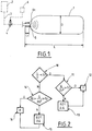
- the filling of pressurized gas tanks 1 can be implemented by a filling device (or station) comprising a source 2 of pressurized gas, a gas transfer pipe 3 connected to the source 2 and provided with minus one flow control valve 4.
- the transfer pipe 3 comprises at least one end intended to be connected to a reservoir 1 to be filled.
- the source 2 of pressurized gas can comprise at least one of: one or more tanks of pressurized gas, at least one compressor, a source of liquefied gas and a vaporizer, etc.
- the end of the transfer pipe 3 intended to be connected to the reservoir 1 forms or comprises an injector 5 having a determined injection diameter D1.
- the device preferably further comprises an electronic filling control member 6 ensuring control of the at least one valve 4 and / or other members of the filling device.
- the device is configured or used to fill a reservoir 1 with pressurized gas up to a target pressure, for example 250 bar or 350 bar or 500 bar or 700 bar or more, in particular 800 or 900 bar.
- a target pressure for example 250 bar or 350 bar or 500 bar or 700 bar or more, in particular 800 or 900 bar.
- the device is in particular designed to preferably fill cylindrical reservoirs 1 in a horizontal position (that is to say lying in their longitudinal direction).
- the reservoirs 1 have a cylindrical shape with a determined internal length L and a determined internal diameter D.
- the end of the transfer line 3 is connected at an orifice located at a longitudinal end of the tank 1.
- the transfer of pressurized gas from the source 2 and the interior of the reservoir 1 is carried out at a determined flow rate Q (in particular a mass flow rate).
- the transfer of gas from the source 2 to the reservoir 1 is adapted to reduce the heating produced in the reservoir 1.
- This adaptation of the gas transfer comprises at least one of a dimensioning of the injection diameter D1, a dimensioning of the flow rate Q of the transferred gas and this modification is carried out according to the ratio L / D between the length L and the diameter D of the tank 1.
- this L / D ratio can delimit two types of tank 1, for example so-called “short” tanks (L / D less than a first threshold S1) and so-called “long” tanks (L / D greater than the first threshold S1 ).
- the inventors have in fact identified that, as a function of this geometric criterion, it is possible to adapt the injection diameter D1 or the flow rate Q of gas transferred to successfully reduce the temperature heterogeneities of the gas in the tank 1, c 'that is to say to reduce excessively hot spots during filling.
- the regulation step preferably consists in maintaining the ratio Q / D1 2 between the mass flow rate Q of the transferred gas and the square of the injection diameter D1 above a second determined threshold S2 (see ref. 11). figure 2 ). If this ratio Q / D1 2 is greater than the second threshold S2, filling F can be carried out without the risk of excessive heating (see ref. 12 figure 2 ).
- Rho is tabulated for each gas according to its temperature and pressure. In other words, for a given temperature and pressure, the density of the gas depends on its nature. Consequently, the Q / D1 2 ratio also depends on the nature of the gas.
- the S2 limit is calculated with the speed value V equal to 5 m / s under the end-of-filling conditions and the S3 limit is calculated with the speed value of 100 m / s for the start-filling conditions.
- the thresholds S2 and S3 are preferably dependent (or a function) of the target pressure for filling the reservoir 1 and preferably also of the nature of the gas.
- Maintaining the ratio Q / D1 2 above a second determined threshold S2 can be easily achieved by adapting the injection diameter D1 (reduction for example) and / or by adapting the mass flow rate Q of filling (increase for example) cf. ref. 13 figure 2 .
- These operating conditions can in particular be frozen before filling or modified before or during filling with a view to the geometry of the reservoirs 1 which will have to be filled to a determined pressure.
- the injection diameter D1 and / or the filling ramp is (are) suitable to meet the above recommendation (see ref. 13, figure 2 ).
- L / D ⁇ S1 is preferably modified as follows: (L-L1) / D ⁇ S1 to take account of the actual length of progression of the injected gas.
- the inventors have demonstrated that there is little or no horizontal temperature heterogeneity, for example because the injected gas jet does not strike the walls of the tank laterally (due to the angle and the usual shape of the gas jet of the injectors used).
- a turbulent mixing regime or a vertically stratified regime is established in the tank 1.
- the temperature is relatively homogeneous (less than 3.5 ° C. between the average temperature and the maximum temperature of the internal wall for an injector with a diameter of 6mm or less than 5.5 ° C for an injector diameter of 10mm).
- a vertically stratified regime temperature gradients of up to 25 ° C. for example can be observed.
- the inventors have demonstrated that the modification of the injection of diameter and / or flow rate to maintain the ratio Q / D1 2 above the second threshold S2 minimizes the risk for establishment of a vertically laminated regime. That is to say that according to this recommendation, a turbulent mixing regime is established which minimizes the temperature heterogeneities. This goes against the recommendations of the prior art which, on the contrary, encouraged a reduction in the filling flow rate in order to limit heating.
- the regulation step preferably consists of maintaining the ratio Q / D1 2 above the second determined threshold S2 and below a third determined threshold S3 (cf. ref. . 14 figure 2 ).
- the regulation step can comprise at least one of: an increase or a decrease in the flow rate Q of transferred gas, an increase or a decrease in the injection diameter D1 cf. ref. 15 figure 2 .
- this recommendation is satisfied, filling F can be carried out without the risk of excessive heating (see ref. 16 figure 2 ).
- the inventors have demonstrated that the above regulations make it possible to control the gas regime in the long tank during filling.
- the vertical and horizontal stratification regimes are reduced. That is to say that the temperature heterogeneities are also reduced for long tanks via this regulation.
- the third determined threshold S3 is preferably dependent (or a function) of the target pressure for filling the reservoir 1 and preferably also of the nature of the gas.
- the Q / D1 2 ratio is maintained above (and possibly below for S3) the thresholds defined above. This is achieved by predefining the injection diameter and / or by adapting the filling mass flow rate. This reduces heating problems by reducing the heterogeneity of gas and tank temperature during filling.
- the calculations to meet these operating conditions are relatively simple and can be easily performed by a computer or a computer to predefine or adapt the operating conditions of a filling station.
- the filling conditions associated with the above examples can be the following: a gas temperature of 0 ° C for filling at 350 bar, -20 ° C, -40 ° C for filling at 500 or 700 bar.
- the final filling speed can be at least 5 m / s.
- an electronic data acquisition and processing storage unit 6 forming part of the station or remotely can be used.
- This electronic device 6 can, if necessary, ensure the control of at least one element of the station, for example the at least one valve 4 of the transfer pipe (for example to regulate the transferred flow).
- the invention is particularly suitable for filling reservoirs 1 arranged horizontally during filling (generating the horizontal cylindrical portion).
- the invention is particularly suitable for filling reservoirs having L / D ratios of, for example, between 1.4 and 6.6.
- these measures apply particularly well to injectors having a diameter of between 3 to 25 mm.
- other geometries or filling configurations are possible (vertical, different dimensions), if necessary with less advantages or requiring small adaptations (thresholds, etc.).
- gas transfer regulation is meant in particular a control (for example dynamic) or a predetermined dimensioning of the filling conditions (D1 and / or Q in particular).
Landscapes
- Engineering & Computer Science (AREA)
- Mechanical Engineering (AREA)
- General Engineering & Computer Science (AREA)
- Filling Or Discharging Of Gas Storage Vessels (AREA)
Applications Claiming Priority (2)
| Application Number | Priority Date | Filing Date | Title |
|---|---|---|---|
| FR1660131A FR3057644B1 (fr) | 2016-10-19 | 2016-10-19 | Procede et dispositif de remplissage d'un reservoir de gaz sous pression |
| PCT/FR2017/052835 WO2018073520A1 (fr) | 2016-10-19 | 2017-10-16 | Procédé et dispositif de remplissage d'un réservoir de gaz sous pression |
Publications (2)
| Publication Number | Publication Date |
|---|---|
| EP3529531A1 EP3529531A1 (fr) | 2019-08-28 |
| EP3529531B1 true EP3529531B1 (fr) | 2020-12-02 |
Family
ID=57750198
Family Applications (1)
| Application Number | Title | Priority Date | Filing Date |
|---|---|---|---|
| EP17794378.4A Active EP3529531B1 (fr) | 2016-10-19 | 2017-10-16 | Procédé et dispositif de remplissage d'un réservoir de gaz sous pression |
Country Status (8)
| Country | Link |
|---|---|
| US (1) | US10816139B2 (da) |
| EP (1) | EP3529531B1 (da) |
| JP (1) | JP7005610B2 (da) |
| KR (1) | KR102390251B1 (da) |
| CN (1) | CN109819668B (da) |
| DK (1) | DK3529531T3 (da) |
| FR (1) | FR3057644B1 (da) |
| WO (1) | WO2018073520A1 (da) |
Families Citing this family (6)
| Publication number | Priority date | Publication date | Assignee | Title |
|---|---|---|---|---|
| DE102018133199A1 (de) * | 2018-12-20 | 2020-06-25 | Hps Home Power Solutions Gmbh | Verfahren zum Einspeichern eines Mediums in eine Druckspeichereinrichtung |
| WO2022108257A1 (ko) * | 2020-11-17 | 2022-05-27 | (주)미래기준연구소 | 실시간 대응 수소충전 제어 방법 및 이를 위한 장치 |
| US12544601B2 (en) | 2022-06-29 | 2026-02-10 | Rescue Air Systems, Inc. | System and method of a ring architecture of a fixed piping system implemented within a safety system of a structure to continuously supply breathable air therewithin |
| US12553626B2 (en) | 2022-06-29 | 2026-02-17 | Rescue Air Systems, Inc. | System and method of a loop architecture of a fixed piping system implemented within a safety system of a structure to continuously supply breathable air therewithin |
| AU2023299082A1 (en) * | 2022-06-29 | 2024-10-24 | Rescue Air Systems, Inc. | Method and system of automatically modifying a rate of filling an air bottle with breathable air in a firefighter air replenishment system based on flow rate detection thereof |
| JP7752100B2 (ja) * | 2022-09-28 | 2025-10-09 | 本田技研工業株式会社 | ガス充填方法 |
Family Cites Families (21)
| Publication number | Priority date | Publication date | Assignee | Title |
|---|---|---|---|---|
| GB2127533B (en) * | 1982-09-30 | 1986-04-23 | Cornelius Co | Filling compressed gas bottles |
| US5641005A (en) * | 1994-12-02 | 1997-06-24 | Gas Research Institute | System and method for charging a container with pressurized gas |
| US7059364B2 (en) * | 2004-02-12 | 2006-06-13 | Gas Technology Institute | Control method for high-pressure hydrogen vehicle fueling station dispensers |
| FR2884592B1 (fr) * | 2005-04-13 | 2007-08-03 | Air Liquide | Procede de controle du remplissage de bouteilles de gaz |
| FR2896028B1 (fr) * | 2006-01-06 | 2008-07-04 | Air Liquide | Procede et dispositif de remplissage de conteneurs de gaz sous pression |
| US8286670B2 (en) * | 2007-06-22 | 2012-10-16 | L'air Liquide Societe Anonyme Pour L'etude Et L'exploitation Des Procedes Georges Claude | Method for controlled filling of pressurized gas tanks |
| FR2920858B1 (fr) * | 2007-09-10 | 2009-11-27 | Air Liquide | Procede de remplissage de conteneur de gaz sous pression |
| FR2933689B1 (fr) * | 2008-07-11 | 2011-03-18 | Air Liquide | Structure de garnissage a hautes performances avec jeux lateraux controles |
| JP5115565B2 (ja) * | 2010-02-15 | 2013-01-09 | トヨタ自動車株式会社 | 車両 |
| US9605804B2 (en) * | 2010-04-21 | 2017-03-28 | Honda Motor Co., Ltd. | Method and system for tank refilling using active fueling speed control |
| US8783303B2 (en) * | 2010-04-21 | 2014-07-22 | Ryan HARTY | Method and system for tank refilling |
| US9347614B2 (en) * | 2010-04-21 | 2016-05-24 | Honda Motor Co., Ltd. | Method and system for tank refilling using active fueling speed control |
| FR2988695B1 (fr) * | 2012-03-27 | 2015-02-20 | Air Liquide | Dispositif et procede de remplissage de reservoir |
| BR112015014661B1 (pt) * | 2012-12-20 | 2021-11-16 | Mosaic Technology Development Pty Ltd | Sistema para o reabastecimento de reservatório de pressão de gás comprimido usando um bocal termicamente acoplado |
| US9279541B2 (en) * | 2013-04-22 | 2016-03-08 | Air Products And Chemicals, Inc. | Method and system for temperature-controlled gas dispensing |
| WO2015055202A1 (en) * | 2013-10-14 | 2015-04-23 | H2 Logic A/S | A method for refueling of gas into a pressurized gas tank |
| JP5901608B2 (ja) * | 2013-12-26 | 2016-04-13 | 本田技研工業株式会社 | 燃料充填システム |
| FR3027999B1 (fr) * | 2014-11-05 | 2016-11-25 | H2Nova | Station d'approvisionnement en hydrogene gazeux et procede associe permettant de determiner avec une precision donnee le debit massique d'hydrogene gazeux |
| FR3033867B1 (fr) * | 2015-03-17 | 2018-06-29 | L'air Liquide, Societe Anonyme Pour L'etude Et L'exploitation Des Procedes Georges Claude | Procede de remplissage de reservoirs avec du gaz sous pression |
| FR3036159B1 (fr) * | 2015-05-12 | 2017-05-05 | Air Liquide | Procede et dispositif de remplissage ou de soutirage d'un reservoir de gaz sous pression |
| US10794538B2 (en) * | 2015-12-11 | 2020-10-06 | Honda Motor Co., Ltd. | Process for refilling a gas tank and gas supply system |
-
2016
- 2016-10-19 FR FR1660131A patent/FR3057644B1/fr not_active Expired - Fee Related
-
2017
- 2017-10-16 KR KR1020197012873A patent/KR102390251B1/ko active Active
- 2017-10-16 CN CN201780063041.7A patent/CN109819668B/zh active Active
- 2017-10-16 US US16/343,058 patent/US10816139B2/en active Active
- 2017-10-16 DK DK17794378.4T patent/DK3529531T3/da active
- 2017-10-16 EP EP17794378.4A patent/EP3529531B1/fr active Active
- 2017-10-16 JP JP2019520051A patent/JP7005610B2/ja active Active
- 2017-10-16 WO PCT/FR2017/052835 patent/WO2018073520A1/fr not_active Ceased
Non-Patent Citations (1)
| Title |
|---|
| None * |
Also Published As
| Publication number | Publication date |
|---|---|
| JP7005610B2 (ja) | 2022-01-21 |
| CN109819668B (zh) | 2021-12-14 |
| US20190277449A1 (en) | 2019-09-12 |
| DK3529531T3 (da) | 2021-02-22 |
| FR3057644B1 (fr) | 2018-10-19 |
| EP3529531A1 (fr) | 2019-08-28 |
| US10816139B2 (en) | 2020-10-27 |
| JP2019531446A (ja) | 2019-10-31 |
| WO2018073520A1 (fr) | 2018-04-26 |
| KR20190071737A (ko) | 2019-06-24 |
| FR3057644A1 (fr) | 2018-04-20 |
| CN109819668A (zh) | 2019-05-28 |
| KR102390251B1 (ko) | 2022-04-25 |
Similar Documents
| Publication | Publication Date | Title |
|---|---|---|
| EP3529531B1 (fr) | Procédé et dispositif de remplissage d'un réservoir de gaz sous pression | |
| EP3628911B1 (fr) | Dispositif et procédé de remplissage de réservoirs de gaz sous pression | |
| CA2635970C (fr) | Procede et dispositif de remplissage de conteneurs de gaz sous pression | |
| EP2191190B1 (fr) | Procede de remplissage de conteneur de gaz sous pression | |
| FR3036159A1 (fr) | Procede et dispositif de remplissage ou de soutirage d'un reservoir de gaz sous pression | |
| WO2016124838A1 (fr) | Procédé et un dispositif de remplissage de réservoir d'hydrogène | |
| EP0319371B1 (fr) | Dispositif de guidage cylindrique à compensation de jeu de fonctionnement pour système d'injection de combustible | |
| FR2933748A1 (fr) | Dispositif injecteur de carburant | |
| EP0843124B1 (fr) | Procédé de transport d'un fluide dans une conduite comportant une structure poreuse | |
| EP4153898A1 (fr) | Réservoir de stockage de gaz liquéfié | |
| FR3111416A1 (fr) | Desurchauffeur de fluide frigorigene sous forme gazeuse et installation mettant en œuvre un cycle frigorifique associee | |
| FR2790515A1 (fr) | Procede et dispositif de mise en oeuvre en fonctionnement transitoire d'un moteur a combustion interne, notamment d'un vehicule automobile | |
| FR2492003A1 (fr) | Dispositif de pompage pour injection de carburant | |
| EP1346145B1 (fr) | Dispositif d'injection d'un carburant gazeux sous forme liquide pour moteur a combustion interne comportant des moyens de transfert de chaleur | |
| FR3101930A1 (fr) | Système de gestion d’un réservoir de Gaz Naturel Liquéfié (GNL) pour véhicule ou unité mobile. | |
| FR2948980A1 (fr) | Accumulateur haute pression de systemes d'injection de carburant | |
| FR3064685A1 (fr) | Procede de stabilisation d’une degradation commandee d’une combustion d’un moteur thermique | |
| FR3161720A1 (fr) | Procédé de distribution d’hydrogène en cascade pour une station de remplissage pour véhicule hydrogène | |
| FR2770261A1 (fr) | Dispositif de limitation de debit de carburant pour moteur a combustion interne a injection | |
| EP0934485B1 (fr) | Procede de verrouillage de l'emmanchement d'un tube en matiere plastique sur un embout | |
| FR3114136A1 (fr) | Stockage cryogénique double | |
| EP1400679B1 (fr) | Système de contrôle du fonctionnement d'un moteur diesel de véhicule automobile | |
| FR2816032A1 (fr) | Dispositif de limitation du remplissage d'un reservoir de fluide tel le gpl | |
| EP3569858A1 (fr) | Moteur fusée solide-hybride amélioré | |
| FR2872224A1 (fr) | Dispositif d'injection de carburant sous pression pour un moteur a combustion interne |
Legal Events
| Date | Code | Title | Description |
|---|---|---|---|
| STAA | Information on the status of an ep patent application or granted ep patent |
Free format text: STATUS: UNKNOWN |
|
| STAA | Information on the status of an ep patent application or granted ep patent |
Free format text: STATUS: THE INTERNATIONAL PUBLICATION HAS BEEN MADE |
|
| PUAI | Public reference made under article 153(3) epc to a published international application that has entered the european phase |
Free format text: ORIGINAL CODE: 0009012 |
|
| STAA | Information on the status of an ep patent application or granted ep patent |
Free format text: STATUS: REQUEST FOR EXAMINATION WAS MADE |
|
| 17P | Request for examination filed |
Effective date: 20190520 |
|
| AK | Designated contracting states |
Kind code of ref document: A1 Designated state(s): AL AT BE BG CH CY CZ DE DK EE ES FI FR GB GR HR HU IE IS IT LI LT LU LV MC MK MT NL NO PL PT RO RS SE SI SK SM TR |
|
| AX | Request for extension of the european patent |
Extension state: BA ME |
|
| DAV | Request for validation of the european patent (deleted) | ||
| DAX | Request for extension of the european patent (deleted) | ||
| GRAP | Despatch of communication of intention to grant a patent |
Free format text: ORIGINAL CODE: EPIDOSNIGR1 |
|
| STAA | Information on the status of an ep patent application or granted ep patent |
Free format text: STATUS: GRANT OF PATENT IS INTENDED |
|
| INTG | Intention to grant announced |
Effective date: 20200422 |
|
| RIN1 | Information on inventor provided before grant (corrected) |
Inventor name: BOURGEOIS, THOMAS Inventor name: AMMOURI, FOUAD |
|
| GRAJ | Information related to disapproval of communication of intention to grant by the applicant or resumption of examination proceedings by the epo deleted |
Free format text: ORIGINAL CODE: EPIDOSDIGR1 |
|
| STAA | Information on the status of an ep patent application or granted ep patent |
Free format text: STATUS: REQUEST FOR EXAMINATION WAS MADE |
|
| INTC | Intention to grant announced (deleted) | ||
| GRAP | Despatch of communication of intention to grant a patent |
Free format text: ORIGINAL CODE: EPIDOSNIGR1 |
|
| STAA | Information on the status of an ep patent application or granted ep patent |
Free format text: STATUS: GRANT OF PATENT IS INTENDED |
|
| GRAS | Grant fee paid |
Free format text: ORIGINAL CODE: EPIDOSNIGR3 |
|
| INTG | Intention to grant announced |
Effective date: 20201002 |
|
| GRAA | (expected) grant |
Free format text: ORIGINAL CODE: 0009210 |
|
| STAA | Information on the status of an ep patent application or granted ep patent |
Free format text: STATUS: THE PATENT HAS BEEN GRANTED |
|
| AK | Designated contracting states |
Kind code of ref document: B1 Designated state(s): AL AT BE BG CH CY CZ DE DK EE ES FI FR GB GR HR HU IE IS IT LI LT LU LV MC MK MT NL NO PL PT RO RS SE SI SK SM TR |
|
| REG | Reference to a national code |
Ref country code: GB Ref legal event code: FG4D Free format text: NOT ENGLISH |
|
| REG | Reference to a national code |
Ref country code: AT Ref legal event code: REF Ref document number: 1341311 Country of ref document: AT Kind code of ref document: T Effective date: 20201215 Ref country code: CH Ref legal event code: EP |
|
| REG | Reference to a national code |
Ref country code: IE Ref legal event code: FG4D Free format text: LANGUAGE OF EP DOCUMENT: FRENCH |
|
| REG | Reference to a national code |
Ref country code: DE Ref legal event code: R096 Ref document number: 602017028922 Country of ref document: DE |
|
| REG | Reference to a national code |
Ref country code: DK Ref legal event code: T3 Effective date: 20210217 |
|
| REG | Reference to a national code |
Ref country code: NL Ref legal event code: FP |
|
| PG25 | Lapsed in a contracting state [announced via postgrant information from national office to epo] |
Ref country code: FI Free format text: LAPSE BECAUSE OF FAILURE TO SUBMIT A TRANSLATION OF THE DESCRIPTION OR TO PAY THE FEE WITHIN THE PRESCRIBED TIME-LIMIT Effective date: 20201202 Ref country code: RS Free format text: LAPSE BECAUSE OF FAILURE TO SUBMIT A TRANSLATION OF THE DESCRIPTION OR TO PAY THE FEE WITHIN THE PRESCRIBED TIME-LIMIT Effective date: 20201202 Ref country code: GR Free format text: LAPSE BECAUSE OF FAILURE TO SUBMIT A TRANSLATION OF THE DESCRIPTION OR TO PAY THE FEE WITHIN THE PRESCRIBED TIME-LIMIT Effective date: 20210303 |
|
| REG | Reference to a national code |
Ref country code: NO Ref legal event code: T2 Effective date: 20201202 |
|
| REG | Reference to a national code |
Ref country code: AT Ref legal event code: MK05 Ref document number: 1341311 Country of ref document: AT Kind code of ref document: T Effective date: 20201202 |
|
| PG25 | Lapsed in a contracting state [announced via postgrant information from national office to epo] |
Ref country code: SE Free format text: LAPSE BECAUSE OF FAILURE TO SUBMIT A TRANSLATION OF THE DESCRIPTION OR TO PAY THE FEE WITHIN THE PRESCRIBED TIME-LIMIT Effective date: 20201202 Ref country code: PL Free format text: LAPSE BECAUSE OF FAILURE TO SUBMIT A TRANSLATION OF THE DESCRIPTION OR TO PAY THE FEE WITHIN THE PRESCRIBED TIME-LIMIT Effective date: 20201202 Ref country code: LV Free format text: LAPSE BECAUSE OF FAILURE TO SUBMIT A TRANSLATION OF THE DESCRIPTION OR TO PAY THE FEE WITHIN THE PRESCRIBED TIME-LIMIT Effective date: 20201202 Ref country code: BG Free format text: LAPSE BECAUSE OF FAILURE TO SUBMIT A TRANSLATION OF THE DESCRIPTION OR TO PAY THE FEE WITHIN THE PRESCRIBED TIME-LIMIT Effective date: 20210302 |
|
| PG25 | Lapsed in a contracting state [announced via postgrant information from national office to epo] |
Ref country code: HR Free format text: LAPSE BECAUSE OF FAILURE TO SUBMIT A TRANSLATION OF THE DESCRIPTION OR TO PAY THE FEE WITHIN THE PRESCRIBED TIME-LIMIT Effective date: 20201202 |
|
| REG | Reference to a national code |
Ref country code: LT Ref legal event code: MG9D |
|
| PG25 | Lapsed in a contracting state [announced via postgrant information from national office to epo] |
Ref country code: SM Free format text: LAPSE BECAUSE OF FAILURE TO SUBMIT A TRANSLATION OF THE DESCRIPTION OR TO PAY THE FEE WITHIN THE PRESCRIBED TIME-LIMIT Effective date: 20201202 Ref country code: CZ Free format text: LAPSE BECAUSE OF FAILURE TO SUBMIT A TRANSLATION OF THE DESCRIPTION OR TO PAY THE FEE WITHIN THE PRESCRIBED TIME-LIMIT Effective date: 20201202 Ref country code: EE Free format text: LAPSE BECAUSE OF FAILURE TO SUBMIT A TRANSLATION OF THE DESCRIPTION OR TO PAY THE FEE WITHIN THE PRESCRIBED TIME-LIMIT Effective date: 20201202 Ref country code: LT Free format text: LAPSE BECAUSE OF FAILURE TO SUBMIT A TRANSLATION OF THE DESCRIPTION OR TO PAY THE FEE WITHIN THE PRESCRIBED TIME-LIMIT Effective date: 20201202 Ref country code: SK Free format text: LAPSE BECAUSE OF FAILURE TO SUBMIT A TRANSLATION OF THE DESCRIPTION OR TO PAY THE FEE WITHIN THE PRESCRIBED TIME-LIMIT Effective date: 20201202 Ref country code: RO Free format text: LAPSE BECAUSE OF FAILURE TO SUBMIT A TRANSLATION OF THE DESCRIPTION OR TO PAY THE FEE WITHIN THE PRESCRIBED TIME-LIMIT Effective date: 20201202 Ref country code: PT Free format text: LAPSE BECAUSE OF FAILURE TO SUBMIT A TRANSLATION OF THE DESCRIPTION OR TO PAY THE FEE WITHIN THE PRESCRIBED TIME-LIMIT Effective date: 20210405 |
|
| PG25 | Lapsed in a contracting state [announced via postgrant information from national office to epo] |
Ref country code: AT Free format text: LAPSE BECAUSE OF FAILURE TO SUBMIT A TRANSLATION OF THE DESCRIPTION OR TO PAY THE FEE WITHIN THE PRESCRIBED TIME-LIMIT Effective date: 20201202 |
|
| REG | Reference to a national code |
Ref country code: DE Ref legal event code: R097 Ref document number: 602017028922 Country of ref document: DE |
|
| PG25 | Lapsed in a contracting state [announced via postgrant information from national office to epo] |
Ref country code: IS Free format text: LAPSE BECAUSE OF FAILURE TO SUBMIT A TRANSLATION OF THE DESCRIPTION OR TO PAY THE FEE WITHIN THE PRESCRIBED TIME-LIMIT Effective date: 20210402 |
|
| PLBE | No opposition filed within time limit |
Free format text: ORIGINAL CODE: 0009261 |
|
| STAA | Information on the status of an ep patent application or granted ep patent |
Free format text: STATUS: NO OPPOSITION FILED WITHIN TIME LIMIT |
|
| PG25 | Lapsed in a contracting state [announced via postgrant information from national office to epo] |
Ref country code: IT Free format text: LAPSE BECAUSE OF FAILURE TO SUBMIT A TRANSLATION OF THE DESCRIPTION OR TO PAY THE FEE WITHIN THE PRESCRIBED TIME-LIMIT Effective date: 20201202 Ref country code: AL Free format text: LAPSE BECAUSE OF FAILURE TO SUBMIT A TRANSLATION OF THE DESCRIPTION OR TO PAY THE FEE WITHIN THE PRESCRIBED TIME-LIMIT Effective date: 20201202 |
|
| 26N | No opposition filed |
Effective date: 20210903 |
|
| PG25 | Lapsed in a contracting state [announced via postgrant information from national office to epo] |
Ref country code: SI Free format text: LAPSE BECAUSE OF FAILURE TO SUBMIT A TRANSLATION OF THE DESCRIPTION OR TO PAY THE FEE WITHIN THE PRESCRIBED TIME-LIMIT Effective date: 20201202 |
|
| PG25 | Lapsed in a contracting state [announced via postgrant information from national office to epo] |
Ref country code: ES Free format text: LAPSE BECAUSE OF FAILURE TO SUBMIT A TRANSLATION OF THE DESCRIPTION OR TO PAY THE FEE WITHIN THE PRESCRIBED TIME-LIMIT Effective date: 20201202 |
|
| REG | Reference to a national code |
Ref country code: CH Ref legal event code: PL |
|
| PG25 | Lapsed in a contracting state [announced via postgrant information from national office to epo] |
Ref country code: IS Free format text: LAPSE BECAUSE OF FAILURE TO SUBMIT A TRANSLATION OF THE DESCRIPTION OR TO PAY THE FEE WITHIN THE PRESCRIBED TIME-LIMIT Effective date: 20210402 |
|
| REG | Reference to a national code |
Ref country code: BE Ref legal event code: MM Effective date: 20211031 |
|
| PG25 | Lapsed in a contracting state [announced via postgrant information from national office to epo] |
Ref country code: MC Free format text: LAPSE BECAUSE OF FAILURE TO SUBMIT A TRANSLATION OF THE DESCRIPTION OR TO PAY THE FEE WITHIN THE PRESCRIBED TIME-LIMIT Effective date: 20201202 |
|
| PG25 | Lapsed in a contracting state [announced via postgrant information from national office to epo] |
Ref country code: LU Free format text: LAPSE BECAUSE OF NON-PAYMENT OF DUE FEES Effective date: 20211016 Ref country code: BE Free format text: LAPSE BECAUSE OF NON-PAYMENT OF DUE FEES Effective date: 20211031 |
|
| PG25 | Lapsed in a contracting state [announced via postgrant information from national office to epo] |
Ref country code: LI Free format text: LAPSE BECAUSE OF NON-PAYMENT OF DUE FEES Effective date: 20211031 Ref country code: CH Free format text: LAPSE BECAUSE OF NON-PAYMENT OF DUE FEES Effective date: 20211031 |
|
| PG25 | Lapsed in a contracting state [announced via postgrant information from national office to epo] |
Ref country code: IE Free format text: LAPSE BECAUSE OF NON-PAYMENT OF DUE FEES Effective date: 20211016 |
|
| PG25 | Lapsed in a contracting state [announced via postgrant information from national office to epo] |
Ref country code: CY Free format text: LAPSE BECAUSE OF FAILURE TO SUBMIT A TRANSLATION OF THE DESCRIPTION OR TO PAY THE FEE WITHIN THE PRESCRIBED TIME-LIMIT Effective date: 20201202 |
|
| PG25 | Lapsed in a contracting state [announced via postgrant information from national office to epo] |
Ref country code: HU Free format text: LAPSE BECAUSE OF FAILURE TO SUBMIT A TRANSLATION OF THE DESCRIPTION OR TO PAY THE FEE WITHIN THE PRESCRIBED TIME-LIMIT; INVALID AB INITIO Effective date: 20171016 |
|
| PG25 | Lapsed in a contracting state [announced via postgrant information from national office to epo] |
Ref country code: MK Free format text: LAPSE BECAUSE OF FAILURE TO SUBMIT A TRANSLATION OF THE DESCRIPTION OR TO PAY THE FEE WITHIN THE PRESCRIBED TIME-LIMIT Effective date: 20201202 |
|
| PG25 | Lapsed in a contracting state [announced via postgrant information from national office to epo] |
Ref country code: MT Free format text: LAPSE BECAUSE OF FAILURE TO SUBMIT A TRANSLATION OF THE DESCRIPTION OR TO PAY THE FEE WITHIN THE PRESCRIBED TIME-LIMIT Effective date: 20201202 |
|
| PGFP | Annual fee paid to national office [announced via postgrant information from national office to epo] |
Ref country code: NO Payment date: 20241023 Year of fee payment: 8 |
|
| PGFP | Annual fee paid to national office [announced via postgrant information from national office to epo] |
Ref country code: GB Payment date: 20241025 Year of fee payment: 8 |
|
| PGFP | Annual fee paid to national office [announced via postgrant information from national office to epo] |
Ref country code: NL Payment date: 20251021 Year of fee payment: 9 |
|
| PG25 | Lapsed in a contracting state [announced via postgrant information from national office to epo] |
Ref country code: TR Free format text: LAPSE BECAUSE OF FAILURE TO SUBMIT A TRANSLATION OF THE DESCRIPTION OR TO PAY THE FEE WITHIN THE PRESCRIBED TIME-LIMIT Effective date: 20201202 |
|
| PGFP | Annual fee paid to national office [announced via postgrant information from national office to epo] |
Ref country code: DE Payment date: 20251021 Year of fee payment: 9 |
|
| PGFP | Annual fee paid to national office [announced via postgrant information from national office to epo] |
Ref country code: DK Payment date: 20251027 Year of fee payment: 9 |
|
| PGFP | Annual fee paid to national office [announced via postgrant information from national office to epo] |
Ref country code: FR Payment date: 20251030 Year of fee payment: 9 |