EP3529593B1 - Verfahren und system zur detektion einer diamantsignatur - Google Patents
Verfahren und system zur detektion einer diamantsignatur Download PDFInfo
- Publication number
- EP3529593B1 EP3529593B1 EP17794932.8A EP17794932A EP3529593B1 EP 3529593 B1 EP3529593 B1 EP 3529593B1 EP 17794932 A EP17794932 A EP 17794932A EP 3529593 B1 EP3529593 B1 EP 3529593B1
- Authority
- EP
- European Patent Office
- Prior art keywords
- scatter
- laser beam
- swir
- signal
- light
- Prior art date
- Legal status (The legal status is an assumption and is not a legal conclusion. Google has not performed a legal analysis and makes no representation as to the accuracy of the status listed.)
- Active
Links
Images


Classifications
-
- G—PHYSICS
- G01—MEASURING; TESTING
- G01N—INVESTIGATING OR ANALYSING MATERIALS BY DETERMINING THEIR CHEMICAL OR PHYSICAL PROPERTIES
- G01N21/00—Investigating or analysing materials by the use of optical means, i.e. using sub-millimetre waves, infrared, visible or ultraviolet light
- G01N21/17—Systems in which incident light is modified in accordance with the properties of the material investigated
- G01N21/25—Colour; Spectral properties, i.e. comparison of effect of material on the light at two or more different wavelengths or wavelength bands
- G01N21/31—Investigating relative effect of material at wavelengths characteristic of specific elements or molecules, e.g. atomic absorption spectrometry
- G01N21/35—Investigating relative effect of material at wavelengths characteristic of specific elements or molecules, e.g. atomic absorption spectrometry using infrared light
- G01N21/359—Investigating relative effect of material at wavelengths characteristic of specific elements or molecules, e.g. atomic absorption spectrometry using infrared light using near infrared light
-
- B—PERFORMING OPERATIONS; TRANSPORTING
- B07—SEPARATING SOLIDS FROM SOLIDS; SORTING
- B07C—POSTAL SORTING; SORTING INDIVIDUAL ARTICLES, OR BULK MATERIAL FIT TO BE SORTED PIECE-MEAL, e.g. BY PICKING
- B07C5/00—Sorting according to a characteristic or feature of the articles or material being sorted, e.g. by control effected by devices which detect or measure such characteristic or feature; Sorting by manually actuated devices, e.g. switches
- B07C5/34—Sorting according to other particular properties
- B07C5/342—Sorting according to other particular properties according to optical properties, e.g. colour
- B07C5/3425—Sorting according to other particular properties according to optical properties, e.g. colour of granular material, e.g. ore particles, grain
-
- G—PHYSICS
- G01—MEASURING; TESTING
- G01N—INVESTIGATING OR ANALYSING MATERIALS BY DETERMINING THEIR CHEMICAL OR PHYSICAL PROPERTIES
- G01N21/00—Investigating or analysing materials by the use of optical means, i.e. using sub-millimetre waves, infrared, visible or ultraviolet light
- G01N21/84—Systems specially adapted for particular applications
- G01N21/85—Investigating moving fluids or granular solids
-
- G—PHYSICS
- G01—MEASURING; TESTING
- G01N—INVESTIGATING OR ANALYSING MATERIALS BY DETERMINING THEIR CHEMICAL OR PHYSICAL PROPERTIES
- G01N21/00—Investigating or analysing materials by the use of optical means, i.e. using sub-millimetre waves, infrared, visible or ultraviolet light
- G01N21/84—Systems specially adapted for particular applications
- G01N21/87—Investigating jewels
-
- G—PHYSICS
- G01—MEASURING; TESTING
- G01N—INVESTIGATING OR ANALYSING MATERIALS BY DETERMINING THEIR CHEMICAL OR PHYSICAL PROPERTIES
- G01N33/00—Investigating or analysing materials by specific methods not covered by groups G01N1/00 - G01N31/00
- G01N33/389—Precious stones; Pearls
-
- B—PERFORMING OPERATIONS; TRANSPORTING
- B07—SEPARATING SOLIDS FROM SOLIDS; SORTING
- B07C—POSTAL SORTING; SORTING INDIVIDUAL ARTICLES, OR BULK MATERIAL FIT TO BE SORTED PIECE-MEAL, e.g. BY PICKING
- B07C2501/00—Sorting according to a characteristic or feature of the articles or material to be sorted
- B07C2501/0018—Sorting the articles during free fall
Definitions
- the present invention relates to diamond detection, for example in the detection of non-liberated diamonds in a flow of rock particles, such as Kimberlite.
- Non-liberated diamonds are those still attached to rock product/particles/gravel such as Kimberlite and other minerals. These non-liberated diamonds can then in turn be misplaced in the beneficiation process, which can result in them being misplaced during dense media separation, DMS, due to their density being below the cut point of the DMS Cyclone and subsequently sent to the tailings.
- Non-liberated diamonds can also be damaged/stressed or severely broken while in the circuit due to them not reporting to the recovery section of the plant, but then reporting to the crushing section and then in turn being broken as the size of the material is reduced to pass the CSS which then in turn damages the diamonds. This constitutes a preventable and unnecessary value loss for a mining company that is processing the deposit, and for the government that receives royalties and taxes on the sale of the diamonds.
- Prior art diamond detection involves excitation by a laser beam and measurement of the laser light scattered by the crystalline structure of diamonds.
- the disadvantage of this basic principle is that other transmissive minerals like Quartz, some calcite etc. scatter as well and may be misplaced in a sorting process resulting in higher yield.
- US5206699A discloses an apparatus for examining objects, comprising means for irradiating a line across the objects with radiation which excites Raman emission, and viewing a narrow band of radiation by substantially filtering out all but the narrow band.
- US2013/0135461A1 discloses a reflectivity absorption system for identifying a target precious or semi-precious material.
- the system can include a detector, a filter system, and an output display.
- US 5 628 410 deals with classifying and sorting objects.
- the object of the present invention is to overcome or alleviate at least one of the abovementioned problems. This is achieved by a method as defined in the independent claims. Advantageous embodiments of the present invention are derived from the subclaims and the following description.
- a method for identifying the presence of partly liberated diamonds in a material stream comprising the steps of:
- Capturing SWIR reflections from the material may comprise reflecting SWIR wavelengths to a SWIR detector.
- Separating the scattered light from the reflected light and capturing only the reflections of the incident beam may comprise detecting in a field of view corresponding in size to the size of the incident beam.
- the method may comprise focusing the reflected light before capture.
- the method may comprise splitting a beam of the light after it has been reflected or scattered by the material to capture both the IR reflection signal and the IR scatter signal.
- the method may comprise converting each of the SWIR signal, the IR scatter signal, and the IR reflection signal into digital signals.
- the method further comprises the step of separating a first portion of said at least one IR scatter-/anti-scatter laser beam after said at least one IR scatter-/anti-scatter laser beam has been scattered by the material from a portion of said at least one IR scatter-/anti-scatter laser beam after said at least one IR scatter-/anti-scatter laser beam has been reflected by the material, and thereafter capturing said first portion of said at least one IR scatter-/anti-scatter laser beam.
- a reflected portion of said at least one IR scatter-/anti-scatter laser beam may be separated from a scattered portion of said at least one IR scatter-/anti-scatter laser beam, and vice versa.
- a reflected portion of said at least one IR scatter-/anti-scatter laser beam may then be captured and used to produce an IR reflection signal.
- a scattered portion of said at least one IR scatter-/anti-scatter laser beam may then be captured and used to produce an IR scatter signal.
- the step of separating a reflected portion of said IR scatter-/anti-scatter laser beam is done by optically filtering scattered light from reflected light.
- This step may alternatively be done by capturing both the reflected and scattered portion of said IR scatter-/anti-scatter laser beam and subtracting the captured reflected portion of said IR scatter-/anti-scatter laser beam therefrom.
- a scatter signal may be achieved either by means of e.g. a mechanical mask filtering reflected light from scattered light, or by means of subtracting reflected light from light that has been both reflected and scattered.
- the step of separating a first portion of said IR scatter-/anti-scatter laser beam is done by optically filtering reflected light from scattered light.
- said at least one IR scatter-/anti-scatter laser beam is at least one monochromatic IR scatter-/anti-scatter laser beam.
- the method further comprises the step of filtering out light having the same polarization as the incident beam, so that only cross-polarized light is captured.
- the method further comprises the step of splitting said IR scatter-/anti-scatter laser beam.
- the method further comprises the step of normalizing the SWIR signal and the IR scatter signal by dividing each by the IR reflection signal.
- the method further comprises the step of scanning said multi-wavelength beam across said material stream.
- the material stream comprises at least one rock particle having a partly liberated diamond.
- the method further comprises forming a two-dimensional space using the normalized SWIR signal and the normalized IR scatter signal to represent the material.
- the two-dimensional space represents multiple rock particles.
- the method further comprises classifying pixels within the two-dimensional space as diamond or other material classes.
- the method further comprises ejecting objects comprising material classified as diamond from a transportation direction of said material stream.
- the multi-wavelength beam of IR light comprises multiple beams of IR light combined in one common beam.
- the multi-wavelength beam of IR light may comprise three beams of IR light combined in one common beam, wherein at least one beam is a beam of SWIR light.
- the method may comprise scanning the beam across the material.
- the material may comprise multiple rock particles.
- the multiple rock particles may form part of a flow of rock particles.
- the method may comprise forming a two-dimensional space using the normalized SWIR signal and the normalized IR scatter signal to represent the material.
- the method may comprise classifying pixels within the two-dimensional space as diamond or other material classes.
- the two-dimensional space may represent a single rock particle.
- the two-dimensional space may represent multiple rock particles.
- the method may be used in a sorting process, wherein objects comprising material classified as diamond may be ejected from a flow path of objects to be sorted.
- an apparatus comprising means for illuminating a material with a multi-wavelength beam comprising at least one monochromatic SWIR laser beam, and at least one IR scatter-/anti-scatter laser beam,
- the means for capturing SWIR reflections from the material may comprise means for reflecting SWIR wavelengths to a SWIR detector.
- the means for reflecting SWIR wavelengths to a SWIR detector may comprise a dichroic mirror.
- the means for filtering out the scattered light and capturing only the reflections of the incident beam may comprise means for detecting in a field of view corresponding in size to the size of the incident beam.
- the means for detecting in a field of view corresponding in size to the size of the incident beam may comprise a detector with an aperture with a diameter corresponding substantially to the cross-sectional diameter of the incident beam.
- the aperture may be defined in a plate or diaphragm.
- the means for capturing the remaining reflections or scattered light from the material and means for producing an IR combined reflection and scatter signal or an IR scatter signal may comprise a detector with a field of view larger than that of the detector for capturing only the reflections of the incident beam, wherein there is an optical filter or mechanical mask arranged to filter out light directly reflected by the material.
- Said optical filter or mechanical mask may be a round disc. Said round disc may be coaxially aligned with the reflected portion of the incident beam.
- said means for separating a reflected portion of said at least one IR scatter-/anti-scatter laser beam after said at least one IR scatter-/anti-scatter laser beam has been reflected by the material from a portion of said at least one IR scatter-/anti-scatter laser beam after said at least one IR scatter-/anti-scatter laser beam has been scattered by the material is for example a pin hole, diaphragm, or other known means. Said pin hole or diaphragm may be arranged to allow the center of the reflected beam to pass therethrough and block out a scattered portion of the light.
- the apparatus may comprise means for filtering out light having the same polarization as the incident beam, so that only cross-polarized light is captured.
- the means for filtering may comprise a polarizing beam splitter.
- the apparatus may comprise means for focusing the reflected light before capture.
- the means for focusing may comprise at least one focusing lens.
- the apparatus may comprise means for splitting a beam of the light reflected and scattered by the material to capture both the IR reflection signal and the IR scatter signal.
- the means for splitting may be a non-polarizing beam splitter.
- the apparatus may comprise means for converting each of the SWIR signal, the IR scatter signal, and the IR reflection signal into digital signals.
- the means for converting may be a digital to analog converter.
- the apparatus may comprise means for normalizing the SWIR signal and the IR scatter signal by dividing each by the IR reflection signal.
- the multi-wavelength beam of IR light comprises multiple beams of IR light combined in one common beam.
- the apparatus may comprise a first IR laser and a second SWIR laser.
- the apparatus may comprise means for combining multiple beams of IR light into one common beam.
- the means may comprise one or more dichroic mirrors.
- the multi-wavelength beam of IR light may comprise three beams of IR light combined in one common beam, wherein at least one beam is a beam of SWIR light.
- the apparatus may comprise means for scanning the beam across the material.
- the means for scanning the beam across the material may comprise a rotating polygon mirror.
- the material may comprise multiple rock particles.
- the multiple rock particles may form part of a flow of rock particles.
- the apparatus may comprise means for forming a two-dimensional space using the normalized SWIR signal and the normalized IR scatter signal to represent the material.
- the apparatus may comprise classifying pixels within the two-dimensional space as diamond or other material classes.
- the two-dimensional space may represent a single rock particle.
- the two-dimensional space may represent multiple rock particles.
- said method is performed by an apparatus comprising:
- said apparatus further comprises means for scanning the beam across the material.
- said means for scanning the beam across the material comprises a rotating polygon mirror.
- said means for illuminating a material with a multi-wavelength beam is at least one monochromatic SWIR laser, and at least one monochromatic IR laser.
- said means for capturing a portion of said at least one monochromatic SWIR laser beam after said monochromatic SWIR laser beam has been reflected and/or scattered by the material is a single PIN diode.
- said means for capturing a first portion of said at least one IR scatter-/anti-scatter laser beam after said at least one IR scatter-/anti-scatter laser beam has been scattered and optionally reflected by the material is a single PIN diode.
- said means for capturing a reflected portion of said at least one IR scatter-/anti-scatter laser beam after said at least one IR scatter-/anti-scatter laser beam has been reflected by the material is a single PIN diode.
- said means for separating a reflected portion of said at least one IR scatter-/anti-scatter laser beam from a scattered portion of said at least one IR scatter-/anti-scatter laser beam is an optical filter.
- a sorting system comprising an apparatus as defined above, further comprising means for ejecting objects comprising material classified as diamond from a flow path of objects to be sorted.
- the means for ejecting objects may be adapted to eject objects while falling.
- a computer readable medium containing program instructions which when executed by a processor cause the processor to perform the above method.
- the apparatus for identifying a diamond signature may form part of a laser scanner. Multiple laser scanners may be provided in a sorting system.
- each may produce a concentrated beam of light.
- the beams of light may be combined into one common beam.
- a polarizing beam splitter may be used to remove any irregularity in the polarization of the common beam.
- Means for directing the beam onto the product may be provided and may comprise at least one mirror.
- the at least one mirror may comprise a rotatable mirror with multiple faces.
- One possible rotatable mirror is a polygon mirror.
- At least one laser preferably operates in the range 700 to 1000nm. For example in the range of 800 to 900 nm, or at 730nm or at 830 nm. At least one laser operates in the range 1100 to 1700 nm, for example in the range of 1110 to 1600 nm, or in the range of 1450 to 1550 nm, or at 1490 nm. At least one additional laser may be provided, for example operating in the range 1100 to 1700 nm, for example in the range of 1110 to 1600 nm, or in the range of 1400 to 1600 nm, or at 1550 nm.
- the method may be used to detect diamond in a flow of rock particles where at least one laser beam may be directed toward the rock particle flow as it moves through a detection zone.
- the laser beams may form part of a light band which moves transversely across the path of the rock particles wherein at least one detector is arranged to detect reflected and scattered light.
- scattered light is meant in this description on the one hand the light which is diffusely reflected at the surface of a product, and on the other hand the light that is emitted by the product as a result of said light band at least partly penetrating it, spreading into it, and thereby making the corresponding part of the product light up.
- the rock particles may be presented as a monolayer of a certain width and speed.
- This layer can be formed either by a chute arrangement or by a belt arrangement.
- Each laser beam may be directed to the particles, when falling from the chute or belt, by a polygon mirror arrangement exciting or illuminating the particles of the feed.
- the light which is directly reflected by the surface of the particle as well as the light scattered within the particle, thus lighting up the area around the direct reflection, may be received via the same polygon mirror and may be measured by photo-electric elements converting the amount of light into an electrical signal.
- Each one of said photo-electric elements may for example be a respective photo-diode.
- the ratio of the reflection intensity and the scattering intensity may be determined by measuring the reflected light separately from the scattered light.
- the signal coming from said detector may be related to or coupled with the position of the beam across the material stream.
- the rotational position of the rotating polygon mirror may be used to determine which part of the material stream is currently being illuminated.
- two consecutive signals from the same sensor may be spatially related to each other in a known manner.
- the signal coming from said detector may electronically modified, for example by multiplying it by a factor which is dependent on the position of the light band, so that a signal is obtained which does not depend on the position of the light band.
- the light stream falling on said detector from the light scattered by part of the product may be adjusted in such a manner that it is independent of the position of said part in said detection zone.
- an adjusting element may be placed between said detector and the place where the product moves through the detection zone, the adjusting element letting through only some of the light scattered by a part the product, in such a manner that the light stream of the scattered light falling on said detector is independent of the position of said part.
- Said adjusting element can advantageously comprise a diaphragm with at least one calibrated opening.
- the diagram may have means to adjust the size of said opening.
- Said diaphragm could advantageously be provided with small, movable plates at the edge of said opening, where said plates enable the size and/or shape of the opening to be adjusted, in such a manner that the light stream falling on said detector is independent of the position of said light band.
- a double scanning system may be used which comprises two scanning systems opposite to one another.
- the present invention further maximizes the recovery of Type I & Ila diamonds.
- Prior art X-ray sorting can miss high quality diamonds having a low number of exclusions.
- the invention provides improved diamond recovery in ore bodies that exhibit poor preferential liberation factors. It may also be desirable to recover diamonds still attached to Kimberlite increasing their value as geological specimens, and the present invention may be used in this regard.
- Figure 1 is a flowchart representing a typical prior art diamond processing flow.
- the process is characterized by a liberation stage which incorporates size classification and comminution unit processes.
- the aim is to liberate the diamonds without damaging them.
- concentration stage the classified material is reduced in mass to obtain a concentrate of smallest possible volume while retaining the highest possible percentage of diamonds.
- this concentrate is then treated in a recovery stage where a final concentrate is produced containing a marketable percentage of diamonds.
- FIG. 2 is a flowchart representing an improved diamond processing flow into which the present invention may be incorporated.
- Figure 3 illustrates one embodiment of a sorter system in accordance with the present invention, suitable for use in a diamond processing flow.
- the main frame 14 of the system represents the support structure for the material guidance, the laser scanner boxes and the ejection module.
- a free fall arrangement with front and rear scanning capabilities is provided.
- the infeed 1 consisting of, for example, kimberlite rocks is fed on to a vibrating or shaking pan feeder 2.
- the purpose of this feeder is to distribute the infeed evenly to the full scanning and separation width of the equipment (typically 300mm to 2000mm wide) and further on to the acceleration chute 4.
- the material changes the feeding direction from a more horizontal orientation to a more vertical orientation guided by the chute 4 and is accelerated up to a speed on app. 3m/s. By this acceleration process is spread even over the area available and most of the particles are liberated and do not touch each other.
- the scanning of the particles by mean of the laser scanners 7 from 2 opposite sides takes place in the gap in the chute forming the scanning zone 5. Another segment of the chute guides the particles further on the nozzle bar of the ejection module.
- one or more solenoid valves are activated releasing compressed air through the related nozzles 8 at the position where a potential liberated or non-liberated diamond 10 has been detected in order to push the particle over the splitter plate 11 which will be caught and guided to the eject outlet 13. All other Kimberlite particles will pass the nozzle bar without activation, will be dropped under the splitter plate and will finally be guided to the drop outlet 12 of the machine.
- Figure 4 shows one embodiment of an apparatus for identifying a diamond signature in accordance with the present invention.
- This system may be incorporated in, or used in combination with, a sorter system, such as that shown in figure 3 .
- Three lasers 20, 22, 23 are provided in this embodiment, each producing a concentrated beam of light which is combined in one common beam by means of dichroic mirrors 19, 21.
- One laser provides an IR scatter-/anti-scatter laser beam.
- the second and the third lasers add wavelengths to support the discrimination of diamonds from all other translucent material, and where at least one of those emits a laser beam having a wavelength in the short wave infrared (SWIR) region.
- SWIR short wave infrared
- Each one of these laser beams is a monochromatic laser beam. More wavelengths can be added / mixed if appropriate to increase selectivity.
- the combined beam is guided to a polarizing beam splitter 18.
- polarizing beam splitter The operating principles of a polarizing beam splitter are understood by those skilled in the art and a detailed explanation thereof is not necessary for purposes of this description.
- laser light is already polarized, and although the polarization of the combined light beam is oriented in such a way that it corresponds with the transmission polarization direction of the beam splitter, any irregularity or imperfection in the polarization of light beam is removed as light beam passes through the polarizing beam splitter 18.
- the combined light beam leaving polarizing beam splitter 18 is directed to a high speed rotating polygon mirror 17.
- the high speed polygon mirror 17 directs the light beam(s) in a scanning plane over the full width of the scanning zone towards a reference or background element 15. It may be preferred to utilize a light gate 16 between the polygon mirror 17 and background element 15. This light gate 16 is described in detail in PCT application WO 98/44335 . In general, the light gate 16 ensures that the light reflected back to the detectors from the scanned bodies is "independent" of the position of the bodies in the scanning pattern of the light beam(s). In this way, a substantially uniform sensitivity is obtained in scanning products across the full width of scanning plane.
- the light gate 16 may be made in the form of a diaphragm having an opening that narrows in the direction of the point of greatest reflected light from the scanned bodies (generally in the middle of the scanning plane). This opening is disposed in a plane perpendicular to the plane in which light beam moves.
- the form and size of the diaphragm opening are chosen so that whenever the light beam is directed towards the products, the signal generated by the detectors receiving the light "retuned" by the scanned products is independent of the position of the products within the scanning plane of the light beam.
- Background element 15 may be made of various materials depending on the type of objects to be scanned, and is preferably of a color or structure which allows to discriminate all particles of the infeed from the background.
- the particles to be scanned pass through scanning zone between background element 15 and mirror 17.
- the light beams impact on the products and a part of the light is reflected back to mirror 17 and polarizing beam splitter 18.
- the reflected light contains light having the same polarization as the incident light beam and light of perpendicular polarizations from the scanned bodies.
- the same polarized light is not particularly useful to the processing circuitry and may even mask certain useful information about the scanned products.
- Polarizing beam splitter 18 will split the reflected light into two polarization directions, one having the same polarization as the incident laser light, the polarization of which had been initially further aligned by the passage of the initial concentrated beam of light from lasers 20, 22, 23 through the same polarizing beam splitter 18, and the other having a 90-degree polarization (cross-polarized light) with respect to the incident laser light.
- the same polarized reflected light is passed directly through beam splitter 18 and is not further used.
- polarizing beam splitter 18 may be thought of as serving a "filtering" function in that it filters the same polarized light from the reflected light.
- the cross polarized light from beam splitter 18 is directed to a focusing lens 24 and then to the dichroic mirror 25.
- the SWIR wavelength can be reflected by this mirror and guided to the SWIR detector arrangement 27 which also includes the components 26, 28 and 29 whereas longer wavelengths pass through the dichroic mirror 25.
- the detector 27 produces a control signal proportional to the entire reflected cross polarized SWIR light field guided to an op-amp 28 and analogue / digital converter 29.
- the light passing through the dichroic mirror 25 is guided to a non-polarizing beam splitter 30 (sometimes referred to in the art as a "50/50 beam splitter”).
- Beam splitter 30 passes about 50% of the cross polarized reflected light to the detector arrangement 33 which includes the components 31, 32, 34 and 35, and about 50% to the detector arrangement 38 which includes the components 37, 39 and 40.
- Each of the detector arrangements 33 and 38 have different field of views.
- Detector 38 has a field of view with a large enough diameter so that essentially all of the cross polarized light reflected from the scanned products, including the light diffused into translucent products (scattered light) and the relatively intense center light reflected from the point of impingement of the incident laser light on the product are captured.
- the detector 38 may be provided with a plate or diaphragm having a cross-sectional diameter the corresponds substantially to the cross-sectional diameter of the beam of cross-polarized light.
- a reference channel is necessary allowing the relative measurement of the scattering effect. This reference channel is formed by the detector 38 arrangement measuring the combined reflected incident light and the scattered light. Detector 33 measures only the reflection of the incident light.
- the field of view of detector 38 is defined by an upstream defining member 36 such as a plate or diaphragm having a relatively large aperture or hole defined there through with a diameter that thus defines the diameter of the field of view.
- the detector 38 produces a control signal proportional to the entire reflected cross polarized light field guided to an op-amp 39 and analogue / digital converter 40.
- the defining member 36 has a portion arranged to block out the relatively intense direct reflected light from the point of impact of the incident light beam on the products. In this embodiment, the reflected light is filtered from the scattered light and a scatter signal may be produced.
- Detector 33 has a field of view corresponding in size essentially to the cross-sectional diameter of the incident scanning light beam. Detector 33 thus senses only the relatively intense direct reflected light from the point of impact of the incident light beam on the products.
- the field of view of detector 33 is defined by an upstream defining member 31 such as a plate or diaphragm having a hole or aperture defined there through with a diameter corresponding to the cross-sectional diameter of the incident laser light beam.
- the detector 33 produces an output signal proportional to the direct reflected light only guided to an op-amp 34 and analogue / digital converter 35.
- All detectors have an upstream defining member 26, 32 and 37 which consists of a polarizing beam splitter in order guide only the cross polarized light to the detector.
- the digital signals of the three detector channels are acquired by the image processing system forming a two-dimensional image which represents the section of sorter feed traveling in between the scanning zone and the nozzle bar of the ejection module of the sorter.
- the image processing system evaluates the data in real time in order discriminate the particles from the background, to classify the particles and to control the valve block for those which should be ejected.
- FIG. 5 is a flow chart of one embodiment of signal processing within an image processing system in accordance with the present invention.
- Figure 5 is flow chart representing one embodiment of the processing of signals generated by the apparatus of Figure 4 in accordance with a method of the present invention, which may be carried out by an image processing system.
- IR _ REF _ SC ′ IR _ REF _ SC / IR _ REF
- SWIR ′ SWIR / IR _ REF
- the three signals IR_REF, IR_REF_SC and SWIR of the appropriate detectors are converted by analogue/digital (A/D) converters to digital values with a resolution of 12 bits.
- a control logic controls the conversion rate and timing as well as the synchronization with the rotating polygon mirror. As an example 2048 A/D conversions take place per mirror face representing one scan over the full width of the material feed representing one line of 2048 pixels.
- the flow chart in figure 5 describes the functions performed on the pixel by pixel level before the area image processing takes place.
- IR_REF_SC' and SWIR' are used to form a two-dimensional space, see Figure 6 .
- the properties of the materials of interest to be discriminated can be describes as clouds of IR_REF_SC', SWIR' values per material forming a material definition space.
- Offline analyzing tools are uses to derive this definition space from representative samples and to setup the feature class generation function.
- the classification function will return a material class identifier whenever SWIR', IR_REF_SC' is member of gravel, quartz or diamond according to the definition shown in Figure 6 .
- the material class identifies may be 0 for gravel and 1 for quartz and 2 for diamond. More classes can be defined for other rock species in the material feed if appropriate.
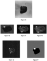
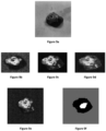
- Figures 7a , 8a and 9a are photographs in normal ambient lighting, showing a respective rock particle comprising a partly liberated diamond.
- the diamond is protruding from the rock in a way such that it is fairly easy to see with the naked eye.
- Figure 8a the diamond is partially embedded inside the rock particle in a way such that it is more difficult to see than the diamond in Figure 7a .
- Figure 9a the diamond is almost completely embedded inside the rock particle and is therefore very difficult to see with the naked eye.
- Figures 7b-d , 8b-d , and 9b-d are grayscale representations of the rock as seen by three different detectors used in the method of the invention.
- Figs. 7b , 8b and 9b are grayscale representations of the rock according to the IR scatter signal
- Figs. 7c , 8c , and 9c are grayscale representations of the rock according to the IR reflection signal
- Figs. 7d , 8d , and 9d are grayscale representations of the rock according to the SWIR signal.
- Figures 7e , 8e , and 9e show false-color representations of the respective rock using the three grayscale representations of Figs. 7b-d , 8b-d , and 9b-d .
- the IR scatter signal is mapped to the red channel
- the IR reflection signal is mapped to the green channel
- the SWIR signal is mapped to the blue channel.
- a false-color RGB image is formed based on these three signals.
- Figs. 7b-e , 8b-e , and 9b-e are then used in the material classification of each pixel. This is e.g. done by applying threshold values to each one of the three grayscale representations, as well as to the false-color RGB image. If a pixel matches certain predetermined criteria, it is classified as comprising either rock, diamond, background material, another translucent material (e.g. quartz), or another material. This classification is done for all pixels in the four representations of the first rock particle.
- Figures 7f , 8f , and 9f are images showing the material classification of the first rock particle of Figures 7a , 8a , and 9a , respectively.
- the material classification is done by analyzing the IR scatter signal, the IR reflection signal, and the SWIR signal, e.g. as described above.
- pixels classified as comprising the background material are colored gray
- pixels classified as comprising the rock particle are colored black
- pixels classified as comprising diamond duee to the presence of a diamond signature in the signals analyzed
- the classification done in this step is used when determining which rock particles in a stream of rock particles should be ejected from the material stream.
- the classification is also used in directing the means for ejecting the rock particles classified as comprising diamond from the stream of material.
- the ejection means are most suitably directed towards the center of the rock particle to which a diamond adheres, it is important to know the outlie of the rock particle as well as whether or not it comprises diamond.
Landscapes
- Physics & Mathematics (AREA)
- Health & Medical Sciences (AREA)
- Life Sciences & Earth Sciences (AREA)
- Chemical & Material Sciences (AREA)
- Analytical Chemistry (AREA)
- Biochemistry (AREA)
- General Health & Medical Sciences (AREA)
- General Physics & Mathematics (AREA)
- Immunology (AREA)
- Pathology (AREA)
- Spectroscopy & Molecular Physics (AREA)
- Engineering & Computer Science (AREA)
- Food Science & Technology (AREA)
- Medicinal Chemistry (AREA)
- Investigating Or Analysing Materials By Optical Means (AREA)
- Investigating Materials By The Use Of Optical Means Adapted For Particular Applications (AREA)
- Sorting Of Articles (AREA)
- Laser Beam Processing (AREA)
- Carbon And Carbon Compounds (AREA)
- Adornments (AREA)
- Collating Specific Patterns (AREA)
Claims (15)
- Verfahren zum Identifizieren des Vorhandenseins teilweise freiliegender Diamanten in einem Materialstrom, wobei das Verfahren folgende Schritte umfasst:Bestrahlen eines Materials mit einem Multiwellenlängenstrahl, der mindestens einen monochromen SWIR-Laserstrahl und mindestens einen Infrarot-Streu-/-Antistreu-Laserstrahl umfasst,Erfassen eines Teils des mindestens einen monochromen SWIR-Laserstrahls, nachdem der monochrome SWIR-Laserstrahl von dem Material reflektiert und/oder gestreut wurde,Erzeugen eines SWIR-Signals, basierend auf dem erfassten Teil des mindestens einen monochromen SWIR-Laserstrahls,Erfassen eines ersten Teils des mindestens einen Infrarot-Streu-/- Antistreu-Laserstrahls, nachdem der mindestens eine Infrarot-Streu-/- Antistreu-Laserstrahl von dem Material gestreut und optional reflektiert wurde,Trennen und danach Erfassen eines direkt reflektierten Teils des mindestens einen Infrarot-Streu-/-Antistreu-Laserstrahls, nachdem der mindestens eine Infrarot-Streu-/-Antistreu-Laserstrahl von dem Material direkt reflektiert wurde, von einem Teil des mindestens einen Infrarot-Streu-/- Antistreu-Laserstrahls, nachdem der mindestens eine Infrarot-Streu-/- Antistreu-Laserstrahl von dem Material gestreut wurde,Erzeugen eines Infrarot-Streusignals, basierend auf dem erfassten ersten Teil des mindestens einen Infrarot-Streu-/-Antistreu-Laserstrahls,Erzeugen eines Infrarot-Reflexionssignals, basierend auf dem erfassten direkt reflektierten Teil des mindestens einen Infrarot-Streu-/- Antistreu-Laserstrahls,Klassifizieren des Materials als Diamanten umfassend, basierend auf dem Vorhandensein einer Diamantensignatur in der Kombination aus dem SWIR-Signal, dem Infrarot- Reflexionssignal und dem Infrarot-Streusignal.
- Verfahren nach Anspruch 1 ferner den Schritt des Trennens eines ersten Teils des mindestens einen Infrarot-Streu-/-Antistreu-Laserstrahls, nachdem der mindestens eine Infrarot-Streu-/-Antistreu-Laserstrahl von dem Material gestreut wurde, von einem Teil des mindestens einen Infrarot-Streu-/-Antistreu-Laserstrahls, nachdem mindestens ein Infrarot-Streu-/-Antistreu-Laserstrahl von dem Material reflektiert wurde, und danach Erfassen des ersten Teils des mindestens einen Infrarot-Streu-/-Antistreu-Laserstrahls umfassend.
- Verfahren nach einem der Ansprüche 1 oder 2, wobei der mindestens eine Infrarot-Streu-/-Antistreu-Laserstrahl mindestens ein monochromer Infrarot-Streu-/-Antistreu-Laserstrahl ist.
- Verfahren nach einem der vorhergehenden Ansprüche, ferner den Schritt des Herausfilterns von Licht mit der gleichen Polarisation wie der einfallende Strahl, so dass nur kreuzpolarisiertes Licht erfasst wird, umfassend.
- Verfahren nach einem der vorhergehenden Ansprüche, wobei der Schritt des Trennens eines direkt reflektierten Teils des Infrarot-Streu-/- Antistreu-Laserstrahls durch optionales Herausfiltern gestreuten Lichts aus direkt reflektiertem Licht erfolgt.
- Verfahren nach einem der vorhergehenden Ansprüche, ferner den Schritt des Aufteilens des Infrarot-Streu-/-Antistreu-Laserstrahls umfassend.
- Verfahren nach einem der vorhergehenden Ansprüche, ferner den Schritt des Normalisierens des SWIR-Signals und des Infrarot-Streusignals durch Teilen eines jeden durch das Infrarot-Reflexionssignal umfassend.
- Verfahren nach einem der vorhergehenden Ansprüche, ferner den Schritt des Abtastens des Materialstroms mittels des Multiwellenlängenstrahls umfassend.
- Verfahren nach einem der vorhergehenden Ansprüche, wobei der Materialstrom mindestens ein Steinpartikel umfasst, das einen teilweise freiliegenden Diamanten aufweist.
- Verfahren nach Anspruch 7, ferner das Bilden eines zweidimensionalen Raumes mit Hilfe des normalisierten SWIR-Signals und des normalisierten Infrarot-Streusignals zum Darstellen des Materials umfassend.
- Verfahren nach Anspruch 10, der zweidimensionale Raum mehrere Steinpartikel darstellt.
- Verfahren nach einem der Ansprüche 10 oder 11, ferner das Klassifizieren von Pixeln in dem zweidimensionalen Raum als Diamant oder andere Materialklassen umfassend.
- Verfahren nach einem der vorhergehenden Ansprüche zur Verwendung in einem Sortierungsprozess, ferner das Ausstoßen von Objekten, die Material umfassen, das als Diamant klassifiziert wird, aus einer Transportrichtung des Materialstroms umfassend.
- Computerlesbares Medium, das Programmanweisungen umfasst, die bei Ausführung durch einen Prozessor den Prozessor veranlassen, das Verfahren nach einem der Ansprüche 1 bis 13 durchzuführen.
- Vorrichtung, Folgendes umfassend:Mittel zum Bestrahlen eines Materials mit einem Multiwellenlängenstrahl, der mindestens einen monochromen SWIR-Laserstrahl und mindestens einen Infrarot-Streu-/-Antistreu-Laserstrahl umfasst,Mittel zum Erfassen eines Teils des mindestens einen monochromen SWIR-Laserstrahls, nachdem der monochrome SWIR-Laserstrahl von dem Material reflektiert und/oder gestreut wurde,Mittel zum Erzeugen eines SWIR-Signals, basierend auf dem erfassten Teil des mindestens einen monochromen SWIR-Laserstrahls,Mittel zum Erfassen eines ersten Teils des mindestens einen Infrarot-Streu-/-Antistreu-Laserstrahls, nachdem der mindestens eine Infrarot-Streu-/- Antistreu-Laserstrahl von dem Material gestreut und optional reflektiert wurde,Mittel zum Trennen und danach Erfassen eines direkt reflektierten Teils des mindestens einen Infrarot-Streu-/-Antistreu-Laserstrahls, nachdem der Infrarot-Streu-/-Antistreu-Laserstrahl von dem Material direkt reflektiert wurde, von einem Teil des mindestens einen Infrarot-Streu-/-Antistreu-Laserstrahls, nachdem der mindestens eine Infrarot-Streu-/-Antistreu-Laserstrahl von dem Material gestreut wurde,Mittel zum Erzeugen eines Infrarot-Streusignals, basierend auf dem erfassten ersten Teil des mindestens einen Infrarot-Streu-/-Antistreu-Laserstrahls,Mittel zum Erzeugen eines Infrarot-Reflexionssignals, basierend auf dem erfassten direkt reflektierten Teil des mindestens einen Infrarot-Streu-/- Antistreu-Laserstrahls,Mittel zum Klassifizieren des Materials als Diamanten umfassend, basierend auf dem Vorhandensein einer Diamantensignatur in der Kombination aus dem SWIR-Signal, dem Infrarot- Reflexionssignal und dem Infrarot-Streusignal.
Applications Claiming Priority (2)
| Application Number | Priority Date | Filing Date | Title |
|---|---|---|---|
| EP16195384 | 2016-10-24 | ||
| PCT/EP2017/077143 WO2018077866A1 (en) | 2016-10-24 | 2017-10-24 | A method and system for detecting a diamond signature |
Publications (2)
| Publication Number | Publication Date |
|---|---|
| EP3529593A1 EP3529593A1 (de) | 2019-08-28 |
| EP3529593B1 true EP3529593B1 (de) | 2023-06-07 |
Family
ID=57226782
Family Applications (1)
| Application Number | Title | Priority Date | Filing Date |
|---|---|---|---|
| EP17794932.8A Active EP3529593B1 (de) | 2016-10-24 | 2017-10-24 | Verfahren und system zur detektion einer diamantsignatur |
Country Status (11)
| Country | Link |
|---|---|
| US (2) | US10598602B2 (de) |
| EP (1) | EP3529593B1 (de) |
| CN (2) | CN112525856B (de) |
| AU (2) | AU2017349176B2 (de) |
| CA (1) | CA3041403C (de) |
| ES (1) | ES2953473T3 (de) |
| FI (1) | FI3529593T3 (de) |
| PL (1) | PL3529593T3 (de) |
| RU (1) | RU2702803C1 (de) |
| WO (1) | WO2018077866A1 (de) |
| ZA (1) | ZA201902191B (de) |
Families Citing this family (8)
| Publication number | Priority date | Publication date | Assignee | Title |
|---|---|---|---|---|
| WO2017160844A1 (en) * | 2016-03-15 | 2017-09-21 | University Of Florida Research Foundation, Incorporated | Haploid seed classification using single seed near-infrared spectroscopy |
| WO2018077866A1 (en) * | 2016-10-24 | 2018-05-03 | Tomra Sorting Nv | A method and system for detecting a diamond signature |
| US10552950B2 (en) * | 2017-05-25 | 2020-02-04 | International Business Machines Corporation | Mapping and encoding gemological features |
| RU2731173C1 (ru) * | 2020-01-10 | 2020-08-31 | Акционерное общество "Инновационный Центр "Буревестник" | Способ рентгенографической сепарации минералов |
| JP7595547B2 (ja) | 2021-10-07 | 2024-12-06 | 株式会社クボタ | 検査装置 |
| CN114602821A (zh) * | 2022-03-28 | 2022-06-10 | 同方威视技术股份有限公司 | 一种选矿装置 |
| EP4556889A1 (de) * | 2023-11-15 | 2025-05-21 | TOMRA Sorting GmbH | Erkennung von ermärlichen |
| NO349343B1 (en) * | 2024-05-15 | 2025-12-15 | Eco Mat As | Material Sorting System and Process |
Citations (1)
| Publication number | Priority date | Publication date | Assignee | Title |
|---|---|---|---|---|
| US5628410A (en) * | 1991-02-20 | 1997-05-13 | Gersan Establishment | Classifying or sorting |
Family Cites Families (25)
| Publication number | Priority date | Publication date | Assignee | Title |
|---|---|---|---|---|
| DE3790473C2 (de) * | 1986-08-20 | 1995-04-27 | De Beers Cons Mines Ltd | Trennverfahren für Diamanten |
| US5206699A (en) * | 1988-05-06 | 1993-04-27 | Gersan Establishment | Sensing a narrow frequency band of radiation and gemstones |
| BE1011076A3 (nl) | 1997-03-28 | 1999-04-06 | Ruymen Marc | Werkwijze en inrichting voor het detecteren van onregelmatigheden in een produkt. |
| CA2241470C (en) * | 1997-06-26 | 2005-06-21 | De Beers Consolidated Mines Limited | Diamond detection using coherent anti-stokes raman spectroscopy |
| US6864970B1 (en) * | 2000-10-11 | 2005-03-08 | Best N.V. | Apparatus and method for scanning products with a light beam to detect and remove impurities or irregularities in a conveyed stream of the products |
| GB0409691D0 (en) * | 2004-04-30 | 2004-06-02 | Titech Visionsort As | Apparatus and method |
| DE202004009165U1 (de) * | 2004-04-30 | 2004-10-07 | Ais Sommer Gmbh & Co.Kg | Vorrichtung zur Sortierung von lichtbrechenden Partikeln |
| KR100603770B1 (ko) | 2005-02-03 | 2006-07-24 | 삼성전자주식회사 | 호환형 광픽업장치 |
| US7768643B1 (en) * | 2006-03-30 | 2010-08-03 | Key Technology, Inc. | Apparatus and method for classifying and sorting articles |
| NO329603B1 (no) * | 2007-11-22 | 2010-11-22 | Integrated Optoelectronics As | Fremgangsmate og system for maling og bestemmelse / gjenkjenning av ulike materialer |
| BE1017898A3 (nl) | 2007-12-14 | 2009-10-06 | Technology & Design B V B A | Sorteerapparaat en werkwijze voor het sorteren van producten. |
| BE1018793A3 (nl) * | 2009-06-17 | 2011-09-06 | Best 2 N V | Werkwijze voor het onderscheiden en sorteren van producten waarbij de concentratie van een bestanddeel van deze producten wordt bepaald. |
| DE102010022455A1 (de) * | 2010-06-02 | 2011-12-08 | Optosort Gmbh | Verfahren und Vorrichtung zum Erkennen eines ein Zielmineral enthaltenden Objektes |
| DE102010052338A1 (de) * | 2010-11-25 | 2012-05-31 | Steinert Elektromagnetbau Gmbh | Verfahren und Einrichtung zur Einzelkornsortierung von Schüttgütern beliebiger Art |
| US9030551B2 (en) * | 2011-05-24 | 2015-05-12 | Discovery Metals, Llc | Ambient reflectivity absorption system for identifying precious or semi-precious materials and associated methods |
| GB2504052B (en) | 2012-03-16 | 2017-05-10 | De Beers Uk Ltd | Sorting aggregate material |
| JP2013210241A (ja) * | 2012-03-30 | 2013-10-10 | Hitachi High-Technologies Corp | ディスク表面検査方法及びその装置 |
| US8743366B2 (en) | 2012-08-31 | 2014-06-03 | Fenwal Controls Of Japan, Ltd. | Light emission portion, photoelectric smoke sensor, and suction-type smoke sensing system |
| WO2015063300A1 (en) | 2013-11-04 | 2015-05-07 | Tomra Sorting Nv | Inspection apparatus |
| WO2015082985A1 (en) | 2013-12-05 | 2015-06-11 | Sahajanand Technologies Pvt Ltd. | Detecting synthetic gemstones using image processing |
| CN204523602U (zh) * | 2015-01-30 | 2015-08-05 | 合肥泰禾光电科技股份有限公司 | 一种物料照明探测设备及应用其的物料分选设备 |
| CN105548111B (zh) | 2015-12-27 | 2018-12-04 | 广州标旗光电科技发展股份有限公司 | 一种批量钻石快速筛查方法 |
| WO2018077866A1 (en) | 2016-10-24 | 2018-05-03 | Tomra Sorting Nv | A method and system for detecting a diamond signature |
| US11536597B2 (en) * | 2017-08-10 | 2022-12-27 | Commonwealth Scientific And Industrial Research Organisation | Device and method for monitoring material flow parameters along a passage |
| CN117120830A (zh) * | 2021-03-19 | 2023-11-24 | 加拿大国家研究委员会 | 基于矿物学分析的矿石样品在线分选系统 |
-
2017
- 2017-10-24 WO PCT/EP2017/077143 patent/WO2018077866A1/en not_active Ceased
- 2017-10-24 CA CA3041403A patent/CA3041403C/en active Active
- 2017-10-24 PL PL17794932.8T patent/PL3529593T3/pl unknown
- 2017-10-24 FI FIEP17794932.8T patent/FI3529593T3/fi active
- 2017-10-24 ES ES17794932T patent/ES2953473T3/es active Active
- 2017-10-24 US US16/344,179 patent/US10598602B2/en active Active
- 2017-10-24 EP EP17794932.8A patent/EP3529593B1/de active Active
- 2017-10-24 CN CN202011434655.1A patent/CN112525856B/zh active Active
- 2017-10-24 CN CN201780065685.XA patent/CN109863388B/zh active Active
- 2017-10-24 AU AU2017349176A patent/AU2017349176B2/en active Active
- 2017-10-24 RU RU2019113051A patent/RU2702803C1/ru active
-
2019
- 2019-04-08 ZA ZA2019/02191A patent/ZA201902191B/en unknown
- 2019-09-26 AU AU2019236717A patent/AU2019236717B2/en active Active
-
2020
- 2020-02-11 US US16/787,430 patent/US10942128B2/en active Active
Patent Citations (1)
| Publication number | Priority date | Publication date | Assignee | Title |
|---|---|---|---|---|
| US5628410A (en) * | 1991-02-20 | 1997-05-13 | Gersan Establishment | Classifying or sorting |
Also Published As
| Publication number | Publication date |
|---|---|
| ZA201902191B (en) | 2020-10-28 |
| US20200173931A1 (en) | 2020-06-04 |
| US10942128B2 (en) | 2021-03-09 |
| CN112525856B (zh) | 2024-07-16 |
| FI3529593T3 (fi) | 2023-09-04 |
| CN109863388A (zh) | 2019-06-07 |
| ES2953473T3 (es) | 2023-11-13 |
| AU2019236717B2 (en) | 2021-06-24 |
| BR112019008144A2 (pt) | 2019-07-02 |
| PL3529593T3 (pl) | 2023-11-20 |
| AU2017349176B2 (en) | 2019-06-27 |
| US20190317023A1 (en) | 2019-10-17 |
| AU2017349176A1 (en) | 2019-06-13 |
| CN109863388B (zh) | 2020-12-25 |
| WO2018077866A1 (en) | 2018-05-03 |
| EP3529593A1 (de) | 2019-08-28 |
| US10598602B2 (en) | 2020-03-24 |
| AU2019236717A1 (en) | 2019-10-17 |
| CA3041403A1 (en) | 2018-05-03 |
| RU2702803C1 (ru) | 2019-10-11 |
| CA3041403C (en) | 2021-02-09 |
| CN112525856A (zh) | 2021-03-19 |
Similar Documents
| Publication | Publication Date | Title |
|---|---|---|
| US10942128B2 (en) | Method and system for detecting a diamond signature | |
| JP4063885B2 (ja) | 分類装置 | |
| CN103221151B (zh) | 用于对来自松散物料的物体进行单粒分选的方法和装置 | |
| AU2003236934B2 (en) | Method and apparatus for identifying and sorting objects | |
| EP1250682B2 (de) | Verfahren zur überwachung von dokumenten | |
| US8422003B2 (en) | Device and method for the classification of transparent component in a material flow | |
| EP0772037B1 (de) | Verfahren und Vorrichtung zum Klassifizieren oder Sortieren von Mineralien | |
| US9924105B2 (en) | System and method for individually inspecting objects in a stream of products and a sorting apparatus comprising such system | |
| JP2010042326A (ja) | 光学式穀粒選別装置 | |
| JPH0285750A (ja) | 狭周波数バンドの放射線および宝石の検知 | |
| AU2002214504B2 (en) | A method and device for recording images of grains from cereals to detect cracking | |
| WO2014076253A1 (en) | Method and apparatus for identifying, sorting or classifying | |
| JP7501771B1 (ja) | 光学式判別装置及び光学式選別装置 | |
| JP2007503294A (ja) | 分類装置及び方法 | |
| BR112019008144B1 (pt) | Método para identificar a presença de diamantes liberados parcialmente em uma corrente de material, mídia legível por computador, e aparelho | |
| EP4556889A1 (de) | Erkennung von ermärlichen | |
| GB2251306A (en) | Monitoring an apparatus which uses scanned radiation. | |
| AU2004100065A4 (en) | Optical Ore Sorter | |
| AU2024300039A1 (en) | Inspection arrangement and method for analysing items |
Legal Events
| Date | Code | Title | Description |
|---|---|---|---|
| STAA | Information on the status of an ep patent application or granted ep patent |
Free format text: STATUS: UNKNOWN |
|
| STAA | Information on the status of an ep patent application or granted ep patent |
Free format text: STATUS: THE INTERNATIONAL PUBLICATION HAS BEEN MADE |
|
| PUAI | Public reference made under article 153(3) epc to a published international application that has entered the european phase |
Free format text: ORIGINAL CODE: 0009012 |
|
| STAA | Information on the status of an ep patent application or granted ep patent |
Free format text: STATUS: REQUEST FOR EXAMINATION WAS MADE |
|
| 17P | Request for examination filed |
Effective date: 20190523 |
|
| AK | Designated contracting states |
Kind code of ref document: A1 Designated state(s): AL AT BE BG CH CY CZ DE DK EE ES FI FR GB GR HR HU IE IS IT LI LT LU LV MC MK MT NL NO PL PT RO RS SE SI SK SM TR |
|
| AX | Request for extension of the european patent |
Extension state: BA ME |
|
| DAV | Request for validation of the european patent (deleted) | ||
| DAX | Request for extension of the european patent (deleted) | ||
| STAA | Information on the status of an ep patent application or granted ep patent |
Free format text: STATUS: EXAMINATION IS IN PROGRESS |
|
| 17Q | First examination report despatched |
Effective date: 20200901 |
|
| GRAP | Despatch of communication of intention to grant a patent |
Free format text: ORIGINAL CODE: EPIDOSNIGR1 |
|
| STAA | Information on the status of an ep patent application or granted ep patent |
Free format text: STATUS: GRANT OF PATENT IS INTENDED |
|
| INTG | Intention to grant announced |
Effective date: 20220228 |
|
| GRAJ | Information related to disapproval of communication of intention to grant by the applicant or resumption of examination proceedings by the epo deleted |
Free format text: ORIGINAL CODE: EPIDOSDIGR1 |
|
| STAA | Information on the status of an ep patent application or granted ep patent |
Free format text: STATUS: EXAMINATION IS IN PROGRESS |
|
| INTC | Intention to grant announced (deleted) | ||
| GRAP | Despatch of communication of intention to grant a patent |
Free format text: ORIGINAL CODE: EPIDOSNIGR1 |
|
| STAA | Information on the status of an ep patent application or granted ep patent |
Free format text: STATUS: GRANT OF PATENT IS INTENDED |
|
| INTG | Intention to grant announced |
Effective date: 20220811 |
|
| GRAS | Grant fee paid |
Free format text: ORIGINAL CODE: EPIDOSNIGR3 |
|
| GRAA | (expected) grant |
Free format text: ORIGINAL CODE: 0009210 |
|
| STAA | Information on the status of an ep patent application or granted ep patent |
Free format text: STATUS: THE PATENT HAS BEEN GRANTED |
|
| AK | Designated contracting states |
Kind code of ref document: B1 Designated state(s): AL AT BE BG CH CY CZ DE DK EE ES FI FR GB GR HR HU IE IS IT LI LT LU LV MC MK MT NL NO PL PT RO RS SE SI SK SM TR |
|
| REG | Reference to a national code |
Ref country code: GB Ref legal event code: FG4D |
|
| REG | Reference to a national code |
Ref country code: CH Ref legal event code: EP Ref country code: AT Ref legal event code: REF Ref document number: 1576519 Country of ref document: AT Kind code of ref document: T Effective date: 20230615 Ref country code: DE Ref legal event code: R096 Ref document number: 602017069747 Country of ref document: DE |
|
| P01 | Opt-out of the competence of the unified patent court (upc) registered |
Effective date: 20230705 |
|
| REG | Reference to a national code |
Ref country code: FI Ref legal event code: FGE |
|
| REG | Reference to a national code |
Ref country code: LT Ref legal event code: MG9D |
|
| REG | Reference to a national code |
Ref country code: SE Ref legal event code: TRGR |
|
| REG | Reference to a national code |
Ref country code: NL Ref legal event code: MP Effective date: 20230607 |
|
| REG | Reference to a national code |
Ref country code: NO Ref legal event code: T2 Effective date: 20230607 |
|
| REG | Reference to a national code |
Ref country code: ES Ref legal event code: FG2A Ref document number: 2953473 Country of ref document: ES Kind code of ref document: T3 Effective date: 20231113 |
|
| PG25 | Lapsed in a contracting state [announced via postgrant information from national office to epo] |
Ref country code: RS Free format text: LAPSE BECAUSE OF FAILURE TO SUBMIT A TRANSLATION OF THE DESCRIPTION OR TO PAY THE FEE WITHIN THE PRESCRIBED TIME-LIMIT Effective date: 20230607 Ref country code: NL Free format text: LAPSE BECAUSE OF FAILURE TO SUBMIT A TRANSLATION OF THE DESCRIPTION OR TO PAY THE FEE WITHIN THE PRESCRIBED TIME-LIMIT Effective date: 20230607 Ref country code: LV Free format text: LAPSE BECAUSE OF FAILURE TO SUBMIT A TRANSLATION OF THE DESCRIPTION OR TO PAY THE FEE WITHIN THE PRESCRIBED TIME-LIMIT Effective date: 20230607 Ref country code: LT Free format text: LAPSE BECAUSE OF FAILURE TO SUBMIT A TRANSLATION OF THE DESCRIPTION OR TO PAY THE FEE WITHIN THE PRESCRIBED TIME-LIMIT Effective date: 20230607 Ref country code: HR Free format text: LAPSE BECAUSE OF FAILURE TO SUBMIT A TRANSLATION OF THE DESCRIPTION OR TO PAY THE FEE WITHIN THE PRESCRIBED TIME-LIMIT Effective date: 20230607 Ref country code: GR Free format text: LAPSE BECAUSE OF FAILURE TO SUBMIT A TRANSLATION OF THE DESCRIPTION OR TO PAY THE FEE WITHIN THE PRESCRIBED TIME-LIMIT Effective date: 20230908 |
|
| PG25 | Lapsed in a contracting state [announced via postgrant information from national office to epo] |
Ref country code: SK Free format text: LAPSE BECAUSE OF FAILURE TO SUBMIT A TRANSLATION OF THE DESCRIPTION OR TO PAY THE FEE WITHIN THE PRESCRIBED TIME-LIMIT Effective date: 20230607 |
|
| PG25 | Lapsed in a contracting state [announced via postgrant information from national office to epo] |
Ref country code: IS Free format text: LAPSE BECAUSE OF FAILURE TO SUBMIT A TRANSLATION OF THE DESCRIPTION OR TO PAY THE FEE WITHIN THE PRESCRIBED TIME-LIMIT Effective date: 20231007 |
|
| PG25 | Lapsed in a contracting state [announced via postgrant information from national office to epo] |
Ref country code: SM Free format text: LAPSE BECAUSE OF FAILURE TO SUBMIT A TRANSLATION OF THE DESCRIPTION OR TO PAY THE FEE WITHIN THE PRESCRIBED TIME-LIMIT Effective date: 20230607 Ref country code: SK Free format text: LAPSE BECAUSE OF FAILURE TO SUBMIT A TRANSLATION OF THE DESCRIPTION OR TO PAY THE FEE WITHIN THE PRESCRIBED TIME-LIMIT Effective date: 20230607 Ref country code: RO Free format text: LAPSE BECAUSE OF FAILURE TO SUBMIT A TRANSLATION OF THE DESCRIPTION OR TO PAY THE FEE WITHIN THE PRESCRIBED TIME-LIMIT Effective date: 20230607 Ref country code: PT Free format text: LAPSE BECAUSE OF FAILURE TO SUBMIT A TRANSLATION OF THE DESCRIPTION OR TO PAY THE FEE WITHIN THE PRESCRIBED TIME-LIMIT Effective date: 20231009 Ref country code: IS Free format text: LAPSE BECAUSE OF FAILURE TO SUBMIT A TRANSLATION OF THE DESCRIPTION OR TO PAY THE FEE WITHIN THE PRESCRIBED TIME-LIMIT Effective date: 20231007 Ref country code: EE Free format text: LAPSE BECAUSE OF FAILURE TO SUBMIT A TRANSLATION OF THE DESCRIPTION OR TO PAY THE FEE WITHIN THE PRESCRIBED TIME-LIMIT Effective date: 20230607 Ref country code: CZ Free format text: LAPSE BECAUSE OF FAILURE TO SUBMIT A TRANSLATION OF THE DESCRIPTION OR TO PAY THE FEE WITHIN THE PRESCRIBED TIME-LIMIT Effective date: 20230607 |
|
| REG | Reference to a national code |
Ref country code: DE Ref legal event code: R097 Ref document number: 602017069747 Country of ref document: DE |
|
| PLBE | No opposition filed within time limit |
Free format text: ORIGINAL CODE: 0009261 |
|
| STAA | Information on the status of an ep patent application or granted ep patent |
Free format text: STATUS: NO OPPOSITION FILED WITHIN TIME LIMIT |
|
| PG25 | Lapsed in a contracting state [announced via postgrant information from national office to epo] |
Ref country code: DK Free format text: LAPSE BECAUSE OF FAILURE TO SUBMIT A TRANSLATION OF THE DESCRIPTION OR TO PAY THE FEE WITHIN THE PRESCRIBED TIME-LIMIT Effective date: 20230607 |
|
| PG25 | Lapsed in a contracting state [announced via postgrant information from national office to epo] |
Ref country code: SI Free format text: LAPSE BECAUSE OF FAILURE TO SUBMIT A TRANSLATION OF THE DESCRIPTION OR TO PAY THE FEE WITHIN THE PRESCRIBED TIME-LIMIT Effective date: 20230607 |
|
| 26N | No opposition filed |
Effective date: 20240308 |
|
| PG25 | Lapsed in a contracting state [announced via postgrant information from national office to epo] |
Ref country code: SI Free format text: LAPSE BECAUSE OF FAILURE TO SUBMIT A TRANSLATION OF THE DESCRIPTION OR TO PAY THE FEE WITHIN THE PRESCRIBED TIME-LIMIT Effective date: 20230607 Ref country code: IT Free format text: LAPSE BECAUSE OF FAILURE TO SUBMIT A TRANSLATION OF THE DESCRIPTION OR TO PAY THE FEE WITHIN THE PRESCRIBED TIME-LIMIT Effective date: 20230607 Ref country code: MC Free format text: LAPSE BECAUSE OF FAILURE TO SUBMIT A TRANSLATION OF THE DESCRIPTION OR TO PAY THE FEE WITHIN THE PRESCRIBED TIME-LIMIT Effective date: 20230607 |
|
| REG | Reference to a national code |
Ref country code: CH Ref legal event code: PL |
|
| REG | Reference to a national code |
Ref country code: BE Ref legal event code: MM Effective date: 20231031 |
|
| PG25 | Lapsed in a contracting state [announced via postgrant information from national office to epo] |
Ref country code: LU Free format text: LAPSE BECAUSE OF NON-PAYMENT OF DUE FEES Effective date: 20231024 |
|
| PG25 | Lapsed in a contracting state [announced via postgrant information from national office to epo] |
Ref country code: LU Free format text: LAPSE BECAUSE OF NON-PAYMENT OF DUE FEES Effective date: 20231024 |
|
| PG25 | Lapsed in a contracting state [announced via postgrant information from national office to epo] |
Ref country code: CH Free format text: LAPSE BECAUSE OF NON-PAYMENT OF DUE FEES Effective date: 20231031 |
|
| PG25 | Lapsed in a contracting state [announced via postgrant information from national office to epo] |
Ref country code: CH Free format text: LAPSE BECAUSE OF NON-PAYMENT OF DUE FEES Effective date: 20231031 |
|
| PG25 | Lapsed in a contracting state [announced via postgrant information from national office to epo] |
Ref country code: BE Free format text: LAPSE BECAUSE OF NON-PAYMENT OF DUE FEES Effective date: 20231031 |
|
| PG25 | Lapsed in a contracting state [announced via postgrant information from national office to epo] |
Ref country code: IE Free format text: LAPSE BECAUSE OF NON-PAYMENT OF DUE FEES Effective date: 20231024 |
|
| PG25 | Lapsed in a contracting state [announced via postgrant information from national office to epo] |
Ref country code: IE Free format text: LAPSE BECAUSE OF NON-PAYMENT OF DUE FEES Effective date: 20231024 |
|
| PG25 | Lapsed in a contracting state [announced via postgrant information from national office to epo] |
Ref country code: BG Free format text: LAPSE BECAUSE OF FAILURE TO SUBMIT A TRANSLATION OF THE DESCRIPTION OR TO PAY THE FEE WITHIN THE PRESCRIBED TIME-LIMIT Effective date: 20230607 |
|
| PG25 | Lapsed in a contracting state [announced via postgrant information from national office to epo] |
Ref country code: BG Free format text: LAPSE BECAUSE OF FAILURE TO SUBMIT A TRANSLATION OF THE DESCRIPTION OR TO PAY THE FEE WITHIN THE PRESCRIBED TIME-LIMIT Effective date: 20230607 |
|
| PG25 | Lapsed in a contracting state [announced via postgrant information from national office to epo] |
Ref country code: CY Free format text: LAPSE BECAUSE OF FAILURE TO SUBMIT A TRANSLATION OF THE DESCRIPTION OR TO PAY THE FEE WITHIN THE PRESCRIBED TIME-LIMIT; INVALID AB INITIO Effective date: 20171024 |
|
| PG25 | Lapsed in a contracting state [announced via postgrant information from national office to epo] |
Ref country code: HU Free format text: LAPSE BECAUSE OF FAILURE TO SUBMIT A TRANSLATION OF THE DESCRIPTION OR TO PAY THE FEE WITHIN THE PRESCRIBED TIME-LIMIT; INVALID AB INITIO Effective date: 20171024 |
|
| REG | Reference to a national code |
Ref country code: AT Ref legal event code: UEP Ref document number: 1576519 Country of ref document: AT Kind code of ref document: T Effective date: 20230607 |
|
| PGFP | Annual fee paid to national office [announced via postgrant information from national office to epo] |
Ref country code: PL Payment date: 20250912 Year of fee payment: 9 |
|
| PGFP | Annual fee paid to national office [announced via postgrant information from national office to epo] |
Ref country code: GB Payment date: 20250904 Year of fee payment: 9 |
|
| PGFP | Annual fee paid to national office [announced via postgrant information from national office to epo] |
Ref country code: FR Payment date: 20250908 Year of fee payment: 9 |
|
| PGFP | Annual fee paid to national office [announced via postgrant information from national office to epo] |
Ref country code: SE Payment date: 20250910 Year of fee payment: 9 |
|
| PGFP | Annual fee paid to national office [announced via postgrant information from national office to epo] |
Ref country code: DE Payment date: 20250902 Year of fee payment: 9 |
|
| PGFP | Annual fee paid to national office [announced via postgrant information from national office to epo] |
Ref country code: NO Payment date: 20251009 Year of fee payment: 9 |
|
| PGFP | Annual fee paid to national office [announced via postgrant information from national office to epo] |
Ref country code: AT Payment date: 20250925 Year of fee payment: 9 |
|
| PGFP | Annual fee paid to national office [announced via postgrant information from national office to epo] |
Ref country code: FI Payment date: 20251014 Year of fee payment: 9 |
|
| PGFP | Annual fee paid to national office [announced via postgrant information from national office to epo] |
Ref country code: TR Payment date: 20251015 Year of fee payment: 9 |
|
| PGFP | Annual fee paid to national office [announced via postgrant information from national office to epo] |
Ref country code: ES Payment date: 20251107 Year of fee payment: 9 |