EP3529600B1 - Procédé pour surveiller l'état fonctionnel d'une installation destinée à analyser des pièces par tomodensitométrie - Google Patents
Procédé pour surveiller l'état fonctionnel d'une installation destinée à analyser des pièces par tomodensitométrie Download PDFInfo
- Publication number
- EP3529600B1 EP3529600B1 EP16788472.5A EP16788472A EP3529600B1 EP 3529600 B1 EP3529600 B1 EP 3529600B1 EP 16788472 A EP16788472 A EP 16788472A EP 3529600 B1 EP3529600 B1 EP 3529600B1
- Authority
- EP
- European Patent Office
- Prior art keywords
- measured
- workpiece
- scatter
- workpieces
- measured values
- Prior art date
- Legal status (The legal status is an assumption and is not a legal conclusion. Google has not performed a legal analysis and makes no representation as to the accuracy of the status listed.)
- Active
Links
Images
Classifications
-
- G—PHYSICS
- G01—MEASURING; TESTING
- G01N—INVESTIGATING OR ANALYSING MATERIALS BY DETERMINING THEIR CHEMICAL OR PHYSICAL PROPERTIES
- G01N23/00—Investigating or analysing materials by the use of wave or particle radiation, e.g. X-rays or neutrons, not covered by groups G01N3/00 – G01N17/00, G01N21/00 or G01N22/00
- G01N23/02—Investigating or analysing materials by the use of wave or particle radiation, e.g. X-rays or neutrons, not covered by groups G01N3/00 – G01N17/00, G01N21/00 or G01N22/00 by transmitting the radiation through the material
- G01N23/04—Investigating or analysing materials by the use of wave or particle radiation, e.g. X-rays or neutrons, not covered by groups G01N3/00 – G01N17/00, G01N21/00 or G01N22/00 by transmitting the radiation through the material and forming images of the material
- G01N23/046—Investigating or analysing materials by the use of wave or particle radiation, e.g. X-rays or neutrons, not covered by groups G01N3/00 – G01N17/00, G01N21/00 or G01N22/00 by transmitting the radiation through the material and forming images of the material using tomography, e.g. computed tomography [CT]
-
- H—ELECTRICITY
- H05—ELECTRIC TECHNIQUES NOT OTHERWISE PROVIDED FOR
- H05G—X-RAY TECHNIQUE
- H05G1/00—X-ray apparatus involving X-ray tubes; Circuits therefor
- H05G1/08—Electrical details
- H05G1/26—Measuring, controlling or protecting
- H05G1/54—Protecting or lifetime prediction
-
- G—PHYSICS
- G01—MEASURING; TESTING
- G01N—INVESTIGATING OR ANALYSING MATERIALS BY DETERMINING THEIR CHEMICAL OR PHYSICAL PROPERTIES
- G01N2223/00—Investigating materials by wave or particle radiation
- G01N2223/60—Specific applications or type of materials
- G01N2223/643—Specific applications or type of materials object on conveyor
-
- G—PHYSICS
- G01—MEASURING; TESTING
- G01N—INVESTIGATING OR ANALYSING MATERIALS BY DETERMINING THEIR CHEMICAL OR PHYSICAL PROPERTIES
- G01N2223/00—Investigating materials by wave or particle radiation
- G01N2223/60—Specific applications or type of materials
- G01N2223/645—Specific applications or type of materials quality control
-
- H—ELECTRICITY
- H05—ELECTRIC TECHNIQUES NOT OTHERWISE PROVIDED FOR
- H05G—X-RAY TECHNIQUE
- H05G1/00—X-ray apparatus involving X-ray tubes; Circuits therefor
- H05G1/08—Electrical details
- H05G1/26—Measuring, controlling or protecting
Definitions
- the invention relates to a method for monitoring the functional state of a system for the computed tomographic examination of workpieces according to claim 1, as well as a corresponding device according to claim 14 and a computer program product according to claim 15.
- a first approach involves the use of measuring elements.
- a reference value for a specific dimension is determined using a calibrated test object, which is then compared with determined measured values during continuously repeated measurements of the test object.
- the disadvantage here is that for many geometries and structures to be examined, it is not possible or not economical to create a calibrated measuring element that corresponds to the measurement technology. Therefore, the measured values determined by a measuring element often do not correspond to the measured values that are relevant when assessing the manufacturing quality of an object being examined. If this first monitoring approach is carried out with a calibrated workpiece, the method is usually limited to geometries that are accessible from the outside, since only these can be calibrated from the outside using measuring technology.
- the ongoing measurement operation must be interrupted for each monitoring of the system with a measuring embodiment, so that the efficiency of the system's use is not optimal.
- the monitoring of the system with a measuring embodiment must usually be repeated at regular intervals in order to achieve sufficient security for the measured values determined with the system.
- the permissible tolerances for measurements using the system are very low, very close monitoring using measuring embodiments may be necessary. This can lead to frequent interruptions in the measurement operation, particularly with very precise measurements with low error tolerances, which greatly limits the efficiency of the system's use.
- a second approach involves monitoring the operating parameters of the system used.
- Operating parameters can be, for example, electrical operating parameters (voltage or current of the X-ray tube) or mechanical parameters, such as reaching target positions and deviations from them. Automated checks of simple image parameters can also be carried out.
- One of the disadvantages here is that this monitoring is not very specific. Therefore, a warning of a system malfunction may be given too early or too late.
- DE 10 2006 048 608 A1 e.g. a method for checking a performance state of an X-ray source and/or an X-ray detector, wherein a set of predeterminable test parameters is selected at least for the X-ray source, wherein X-rays emanating from the X-ray source strike at least a partial area of the X-ray detector and are detected by the X-ray detector, wherein at least one characteristic variable characterizing the X-ray source and/or at least one characteristic variable characterizing the X-ray detector is recorded.
- the at least one recorded characteristic variable is compared with a reference characteristic variable corresponding to the recorded characteristic variable, wherein a deviation of the recorded characteristic variable from the reference characteristic variable is used as a measure of the performance state of the X-ray source and/or the X-ray detector.
- the present invention is based on the object of providing an improved method for monitoring the functional state of a system for the computed tomographic examination of workpieces, which overcomes the aforementioned disadvantages of the prior art.
- the invention relates to a computer-implemented method for monitoring the functional state of a system for the computed tomographic examination of workpieces.
- a computed tomographic examination of a workpiece using the system comprises carrying out one or more computed tomographic measurements on the workpiece, wherein the computed tomographic measurements carried out by the system each produce at least one measured value for at least one measured variable.
- the method for monitoring the functional state first comprises selecting measured values for at least one measured variable from at least two computed tomographic measurements on one or more workpieces. Then at least one measure of dispersion is determined for the selected measured values of the at least one measured variable and at least one reference measure of dispersion for measured values of the at least one measured variable.
- the functional state of the system is then determined by comparing the at least one determined measure of dispersion with the at least one reference measure of dispersion for the at least one measured variable.
- the measure of dispersion contains information about the distribution of the measured values.
- Measurement data is obtained from at least one computer tomography image or image of a tomographed workpiece. It is therefore entirely possible that a data set obtained from a computer tomography image for a workpiece being examined is evaluated several times, so that one or more measurement values are determined from a single data set for one or more measurement variables.
- a plurality of measurements does not necessarily mean a plurality of images by the computer tomography system.
- a "measured quantity” can be understood as a specific dimensional property of a workpiece that can be measured dimensionally or as part of a non-destructive test.
- a measured quantity can be the position of an edge in the workpiece, the diameter of a hole, the density and/or size and/or position of pores in a workpiece or something similar.
- a measured quantity does not necessarily have to be a dimensional property of a workpiece. Rather, a measured quantity can also be a quantity that is not determined from the image of the workpiece generated by a recording, but from the image of the recording itself.
- measured values for such a measured quantity can also be determined from a projection image generated during a recording or from the reconstructed volume data in the vicinity of the suspected object surface. Examples of such measured quantities would be gray value distributions or noise values in defined areas of a projection image or the reconstructed volume.
- measurement variables derived from the projection images generated during a recording has the advantage that the raw data of the recording can be used to assess the status of the system.
- dimensional measurement variables of the workpieces first require a reconstruction of the workpiece being examined by back-projecting the projection data. Filters are usually used to obtain the sharpest possible image. However, this results in the loss of information that can be useful for assessing the functional status of the computer tomography system used.
- a measured value can be a length measurement, a density, or another value that does not characterize the workpiece itself, but the recorded image.
- a measured quantity does not necessarily have to be a directly measurable quantity, such as an edge length. Rather, a measured quantity can also be a derived quantity, such as an average surface quality in a certain area of a workpiece being examined.
- a measured quantity can also be a gray value in a certain area, or a signal-to-noise ratio of a recording.
- measured quantities can also be derived from measured values determined during the measurements, which allow measurements to be compared with one another.
- At least one measure of dispersion for the measured values for the measured variable under consideration is determined from the measured values from at least two measurements on one or more workpieces.
- a measure of dispersion is a measure that contains information about the distribution of the measured values.
- the measure of dispersion can, for example, be a variance, an interval or a standard deviation of the measured values.
- the degree of dispersion indicates a parameter with which the functional state of the system can be determined.
- the scatter measure determined in this way is then compared with a reference scatter measure in the further course of the process in order to determine the functional status of the system.
- the reference scatter measure can be retrieved from a database, for example.
- the reference scatter measure can also be a measure that represents statistics or a distribution of measured values.
- the reference scatter measure does not necessarily have to be the same type of scatter measure as the scatter measure determined from the measured values.
- the functional state of the system can be determined by determining a difference between the at least one determined scatter measure and the at least one reference scatter measure and comparing the determined difference with at least one permissible value range for the difference. If the difference lies outside the at least one permissible value range, information is output, the information indicating that the determined difference lies outside at least one permissible value range.
- a “difference" between a scatter measure and a reference scatter measure can be understood as a difference between the two values, for example, or a percentage deviation or something similar.
- a difference can also be determined by checking how much an interval defined by the scatter measure coincides with an interval defined by the reference scatter measure, i.e. how large the intersection is. If the difference determined is outside at least one permissible value range, information is output.
- the information can be output by the CT scanner itself, for example in the form of an optical or acoustic warning signal, or the information can be passed on in digital form in the form of a signal to a peripheral device and processed there. For example, when the information is passed on to a peripheral device, a log file is created in which the deviations or differences determined are noted. Such a log file could then be used, for example, to plan maintenance of the CT scanner.
- a type of "traffic light” could be implemented for the functional status of the computer tomograph. If the determined difference is within a first value range, it is assumed that the computer tomograph is functioning very well, so that no maintenance measures are necessary. and the values determined can be trusted without restriction. If the differences determined are outside the first value range but still within the second value range, it is assumed that the CT scanner is no longer functioning optimally but that no maintenance measures are currently necessary. However, it can be assumed that maintenance will be necessary in the foreseeable future, so an appropriate maintenance plan is drawn up.
- the difference determined is outside the first and second value ranges, it can be assumed that the CT scanner is no longer delivering sufficiently accurate measurement results and that maintenance of the CT scanner is necessary.
- the information which is output as soon as the difference determined is outside a value range also includes an indication of the value range or value ranges that have been left.
- the information output can also be used to block workpieces from further production or use because the CT system did not guarantee a valid measurement.
- the information output can also be used to initiate a check of the monitored system using a measuring embodiment.
- a measuring embodiment By checking using a measuring embodiment, it can then be tested whether the difference in the scatter measurements determined, which led to the output of the information, was actually caused by a faulty computer tomography system. It can also happen that the production of the workpieces examined is subject to systematic errors, for example caused by a production temperature that is too high or other faulty system parameters. Such sources of error can also arise gradually. This would also result in systematic deviations of the measured values from the measured variables under consideration, which could lead to a deviation of the scatter measurement ultimately determined from the measured values from the reference scatter measurement. This deviation could then be erroneously interpreted as being due to a malfunction of the measuring device. However, this incorrect interpretation can be avoided by checking using a measuring embodiment.
- the described embodiment In addition to distinguishing whether a deviation in the scatter measurements is caused by faulty production or faulty recording, the described embodiment also has the advantage that the generally complex check using a measuring standard is only carried out if a specific reason for this can be derived from the ongoing evaluation of measurement results.
- the previously described regular Monitoring of the system using a measuring device could thus be modified to provide monitoring based on requirements. This effectively reduces the number of interruptions to measurement operations for calibration using a measuring device compared to regular calibration and ultimately optimizes them, effectively increasing the efficiency of the system's use.
- determining the functional status of the system can also include determining a temporal progression of the determined scatter measures for a measured variable. By comparing the determined progression with the at least one reference scatter measure, it is then estimated when a difference between the scatter measure and the reference scatter measure will lie outside at least one permissible value range for the difference. In this way, for example, a prediction can be made as to when the images from the computer tomograph will no longer be accurate enough to provide representative information about the quality of the workpieces examined due to ongoing signs of wear.
- the reference scatter used to determine the functional status of the system can be retrieved from a database, for example.
- the at least one reference scatter is determined in a training phase.
- the training phase initially comprises the selection of reference measured values for at least one measured variable from a reference measurement series with a plurality of measurements on a plurality of workpieces.
- the at least one reference scatter is then determined from the selected reference measured values of the at least one measured variable of the reference measurement series.
- the training phase is carried out immediately after the system for the computer tomographic examination of workpieces has been repaired and put back into operation. It is assumed that after the system has been repaired, the images taken by the system are accurate or contain as few errors as possible. The reference scatter measurements determined in the training phase can therefore be considered to be as accurate as possible.
- the training phase described above for determining one or more reference scatter measures can be repeated at regular or irregular intervals and/or after examining a certain number of workpieces. For example, it can be planned that the training phase is repeated after every 50, 100 or 200 workpieces examined or after a certain period of time or at defined times. Combined profiles can also be defined which determine the implementation of the training phase. For example, it can be specified that the training phase is carried out after 200 images or after 2 hours of operation, whichever comes first. In this way, changes to the computer tomograph used can be taken into account, which can lead to a systematic change in the measured values, but are not due to wear and tear on the computer tomograph.
- the operation of the computer tomograph will lead to system components heating up, which in turn can lead to a systematic change in the measured values.
- there may be different workloads at different times during the day-to-day operation of the system which are taken into account when determining the reference scatter measures by repeating the training phase.
- the result of a training phase may be a complete renewal or only a partial update of the reference scatter measures.
- a further embodiment provides that at least one reference scatter measure is dependent on an environmental parameter of the system.
- An "environmental parameter" can be understood as the ambient temperature, the time of day, the weather, the running time of the system or similar.
- repeated training phases can be used to One or more reference scatter measures are determined, whereby a correlation between the reference scatter measures and the environmental parameters can be determined by simultaneously recording the environmental parameters. This correlation can then be used to take systematic inaccuracies in the recording of measurement data, which are not based on wear and tear of the system, into account and to evaluate them accordingly.
- reference scatter measures can be stored in a database for different sets of environmental parameters, which are used to monitor the functional status of the system depending on the prevailing environmental parameters.
- environmental parameters can also take other aspects such as production machine operators, measurement technology operators and production tolerances into account.
- the measured values are determined from one or more projection images of the workpiece under investigation and/or from a three-dimensional reconstruction of the workpiece under investigation created using the projection images of the workpiece under investigation.
- a further embodiment provides that the selection of measured values, the determination of a scatter measure for the selected measured values and the determination of the functional status of the system are repeated after each examination of at least one workpiece. For example, after 5, 10, 50 or 100 workpieces, the functional status of the system can be determined again in accordance with the invention described above.
- the density of determinations of the functional status i.e. the number of workpiece tests after which a determination of the functional status is carried out again using scatter measures
- the desired test density and the computing load caused by a test must be taken into account. These two factors must be weighed against each other depending on the requirements and available resources.
- the density of the tests is not constant over time, but varies depending on external parameters.
- the test density is selected to be very high shortly after the system is started and initially decreases as the operating time increases.
- the test density is increased again after a certain period of operation, since defects or wear and tear of the system are more likely to occur after a longer period of operation.
- the test density can also depend on external parameters such as ambient temperature, or can be specifically increased at short notice by a plant manager using a corresponding The latter can happen, for example, if the specified tolerances for the quantities to be measured or checked change or if the tolerance utilization of the workpieces changes.
- the measured values for determining the degree of scatter are selected from measurements on workpieces that follow one another directly. In this way, a good snapshot of the condition of the system can be realized.
- the measured variables used to determine the scatter dimensions include workpiece-specific measured variables, whereby the workpiece-specific measured variables can only be determined on a specific type of workpiece.
- a workpiece-specific measured variable is therefore, for example, a dimension of a specific geometry of the workpiece being examined or an average local surface quality in a spatially precisely specified workpiece domain.
- the use of workpiece-specific measured variables to determine the scatter dimensions has the advantage that any fluctuations that occur affect exactly those measured values that are also used, for example, to assess the quality of the workpieces being tested. Accordingly, in this embodiment it is very unlikely that a change in the functional state of the system, which causes inaccurate or no longer representative measured values, will not be detected due to an unfavorable choice of measured values.
- these workpiece-specific measured variables ensure that changes in the system that are irrelevant to the measured variable do not lead to a statement about a system error. Monitoring is therefore more efficient and economical.
- the measurement variables used to determine the scatter dimensions include workpiece-unspecific measurement variables, whereby the workpiece-unspecific measurement variables can be determined on different types of workpieces.
- a workpiece-unspecific measurement variable can, for example, be the worst signal-to-noise ratio of the material gray values in the relevant workpiece domains across the sample.
- the dimensions of standardized workpiece sections, such as standardized screw holes, could also be used to determine a workpiece-unspecific measurement variable.
- the use of workpiece-unspecific measurement variables has the advantage that different workpieces can be scanned with one and the same computer tomography system. can be checked and an assessment of the functional status of the system is still possible from the measurements on the different workpieces. This makes the application scenarios of the monitoring carried out more flexible.
- the measured values selected for determining the at least one degree of scatter come from at least one defined partial area of a workpiece, for which a degree of scatter determined from the measured values for a measured variable can be compared with the reference degree of scatter for the measured variable.
- a partial area of a workpiece can be selected that is of particular relevance for the quality inspection of the workpiece.
- the pore density in a structurally important section of an examined workpiece is used for the reference degree of scatter. In this way, it can also be ensured that a change or deterioration in the functional state of the system is reliably detected, especially for relevant measured variables.
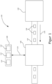
- the Figure 1 shows a schematic representation of an environment 100 in which the method according to the invention can be used.
- the environment 100 is a production environment in which, by way of example, a manufacturing system 102 is arranged, which is designed to produce workpieces 104.
- the manufacturing system 102 can, for example, be an injection molding system for producing injection molded parts.
- the workpieces 104 produced in this way are then fed to a system 106 for computer tomographic examination of the workpieces 104. This can be done, for example, by means of a conveyor belt 118 shown as an example with the running direction 120.
- the structure shown could be used to carry out in-line testing of workpieces 104 produced by the manufacturing system 102.
- the workpieces 104 are to be checked for their manufacturing quality. On the basis of this check, it can be decided, for example, whether a workpiece 104 meets a set of minimum quality requirements and can therefore be sold/distributed, or whether the workpiece 104 is to be regarded as rejects due to inadequate manufacturing quality.
- the system 106 is designed, for example, to generate radiographic projection images of the checked workpieces 104, which can be analyzed using an EDP system 108 assigned to the system 106.
- the EDP system 108 is equipped for this purpose with at least processor means 110, storage means 112 and display means 114 and is connected to the system 106 via a communication link 116.
- the analysis by the computer system 108 can refer both to the recorded radiographic projection images and to representations of the workpiece 104 being examined that are reconstructed from the radiographic projection images. Both three-dimensional and two-dimensional reconstructions of the workpiece 104 can be used for the analysis. Measurement data can be sent to the computer system 108 via the communication connection 116. which can be stored there in the storage means 112 and/or processed by the processor means 110.
- the processor means 110 can be, for example, one or more single-core or multi-core processors.
- the storage means 112 can be any form of data storage.
- the display means 114 can be implemented, for example, by one or more monitors and/or signal lights.
- the EDP system 108 is shown here purely as an example as a coherent unit.
- the EDP system 108 can of course also be a system of computer systems.
- the individual computer systems do not necessarily have to be spatially grouped. Rather, a distributed computer system can also be used as the EDP system 108, for example in the sense of cloud computing.
- the computer system 108 is designed using appropriate software to determine measured values for various measured variables of the workpieces.
- a measured variable can be an edge position, an average surface quality, a material density, a pore density or similar variables.
- a measured variable can also be workpiece-unspecific and indicate a measure of the image quality of the recorded projection images. The measured values determined for these measured variables are then checked against permissible value ranges or limit values and, based on the agreement with the value ranges and/or limit values, it is determined whether a workpiece 104 meets the quality requirements.
- the computer system 108 is designed by means of the method according to the invention to derive an evaluation or monitoring of the functional state of the system 106 from the measured values of the workpieces 104 in addition to an assessment of their quality.
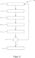
- FIG. 2 The method according to the invention is Figure 2 in the form of a flow chart 200.
- measurement data for the workpiece(s) 104 are initially determined by means of a computer tomographic image of at least one workpiece 104.
- measurement values for one or more measurement variables are then determined for the at least one workpiece 104.
- These can be the same measurement variables that are also used to evaluate the quality of the workpieces 104.
- a set of measured values are then selected in step 204 that are to be used to determine the functional state of the system 106. For example, measured values from measurements on workpieces 104 that follow one another directly can be used in order to achieve the highest possible monitoring density. However, it is also possible that only measurements on a single workpiece 104 are used. Furthermore, measured values that have the lowest possible measurement uncertainty are preferably used to assess the functional state.
- the measure of dispersion is a statistical measure, such as the variance, a value interval, or the like.
- step 204 In order to obtain the best possible assessment of the statistics of the measured values, it is advisable to select a sufficiently large sample in step 204. However, it should also be taken into account that a sample that is too large entails a high data processing effort, so a balance should be made here according to the requirements and available resources.
- a reference degree of scatter is also determined in step 208.
- the reference degree of scatter should preferably provide information on the statistics of exactly the measurement variable that is used to determine the degree of scatter or the degrees of scatter in step 206.
- the type of reference degree of scatter does not necessarily have to be the same type of statistical information that was selected to determine the degree of scatter of the measured values. It can be provided that reference degrees of scatter are stored in the storage means 112 of the computer system 108, so that to determine the reference degrees of scatter only the storage means 112 has to be accessed and the required reference degrees of scatter are retrieved.
- the reference scatter measurements can be determined in a separate training phase.
- measured values from measurements on workpieces 104 are selected and statistical measurements are determined from the selected measured values, which are then used as the reference scatter measurement.
- Such a training phase is preferably carried out shortly after or directly after a repair of the system 106, since at this point it can be assumed that the system is in the best possible condition and thus delivers representative results.
- the use of such a training phase can also have the advantage that measured values from measurements on the same workpieces 104 can be used to determine the reference scatter measurements, the quality of which is then to be assessed based on the images of the system 106. In this way, workpiece-specific measured variables can also be used in particular to evaluate the functional state of the system 106.
- reference scatter measurements are determined repeatedly during operation. This can, for example, prevent a systematic drift in the recorded measured values, which cannot be attributed to wear or a fault in the system 106. is taken into account. Accordingly, different reference scatter measures can exist for one and the same measured variable, which are applied depending on other parameters, such as the ambient temperature, the time of day or operating time of the system 106. Furthermore, a reference scatter measure can also consist of several values. For example, the reference scatter measure for a certain measured variable can include a mean value and a standard deviation.
- a comparison of the scatter measures i.e. the scatter measure determined from the measured values, with the reference scatter measure(s) takes place in step 210.
- the functional state of the system 106 is then derived from this comparison. For example, a difference between the scatter measure and the reference scatter measure can be determined.
- the meaning of the term "difference" depends on the type of scatter measure used.
- step 212 From the comparison of the scatter measure(s) with corresponding reference scatter measures, a decision is made in step 212 as to whether the condition of the system 212 is sufficient to provide representative results or whether maintenance is necessary.
- the inspection of workpieces 104 is continued unchanged. If, however, it is determined that the condition of the system 106 is no longer sufficient, a warning can be issued in step 214.
- the warning can be a visual or acoustic signal.
- information describing the state of the system 106 is generated and stored, for example, in the storage means 112 of the computer system 108.
- a temporal progression of the state of the system 106 can be determined, from which a point in time can be extrapolated at which the system 106 will no longer work sufficiently accurately. This allows an optimized usage and/or maintenance plan to be created for the system 106.
Landscapes
- Health & Medical Sciences (AREA)
- General Health & Medical Sciences (AREA)
- Chemical & Material Sciences (AREA)
- General Physics & Mathematics (AREA)
- Biochemistry (AREA)
- Pathology (AREA)
- Physics & Mathematics (AREA)
- Life Sciences & Earth Sciences (AREA)
- Immunology (AREA)
- Analytical Chemistry (AREA)
- Radiology & Medical Imaging (AREA)
- Nuclear Medicine, Radiotherapy & Molecular Imaging (AREA)
- Engineering & Computer Science (AREA)
- Pulmonology (AREA)
- Theoretical Computer Science (AREA)
- Toxicology (AREA)
- Analysing Materials By The Use Of Radiation (AREA)
- Length-Measuring Devices Using Wave Or Particle Radiation (AREA)
- Crystallography & Structural Chemistry (AREA)
Claims (15)
- Procédé mis en œuvre par ordinateur de surveillance de l'état de fonctionnement d'un équipement (106) destiné à l'analyse tomodensitométrique de pièces ouvrées (104), l'analyse tomodensitométrique d'une pièce ouvrée (104) au moyen de l'équipement (106) comprenant la réalisation d'une ou plusieurs mesures tomodensitométriques sur la pièce ouvrée (104), les mesures tomodensitométriques réalisées par l'équipement (106) produisant respectivement au moins une valeur de mesure pour au moins une grandeur de mesure, le procédé de surveillance de l'état de fonctionnement comprenant les étapes suivantes :* sélection de valeurs de mesure pour au moins une grandeur de mesure à partir de deux mesures tomodensitométriques sur une ou plusieurs pièces ouvrées (104),* détermination d'au moins un indice de dispersion pour les valeurs de mesure sélectionnées de l'au moins une grandeur de mesure,* détermination d'au moins un indice de dispersion de référence pour des valeurs de mesure de l'au moins une grandeur de mesure, et* détermination de l'état de fonctionnement de l'équipement (106) par comparaison de l'au moins un indice de dispersion déterminé avec l'au moins un indice de dispersion de référence pour l'au moins une grandeur de mesure,l'indice de dispersion présentant une information à propos d'une distribution des valeurs de mesure.
- Procédé selon la revendication 1, caractérisé en ce que la détermination de l'état de fonctionnement de l'équipement (106) comprend les étapes suivantes :* détermination d'une différence entre l'au moins un indice de dispersion déterminé et l'au moins un indice de dispersion de référence,* comparaison de la différence déterminée avec au moins une plage de valeurs admissibles pour la différence,* lorsque la différence se trouve en-dehors de l'au moins une plage de valeurs admissibles, délivrance d'une information,l'information indiquant que la différence se trouve en-dehors d'au moins une plage de valeurs admissibles.
- Procédé selon la revendication 1 ou 2, caractérisé en ce que la détermination de l'état de fonctionnement de l'équipement (106) comprend la détermination d'une évolution dans le temps de l'indice de dispersion déterminé pour une grandeur de mesure, la comparaison de l'évolution déterminée avec l'au moins un indice de dispersion de référence permettant d'estimer à quel moment une différence entre l'indice de dispersion et l'indice de dispersion de référence se trouvera en-dehors d'au moins une plage de valeurs admissibles pour la différence.
- Procédé selon l'une des revendications précédentes, caractérisé en ce que l'au moins un indice de dispersion de référence est déterminé dans une phase d'entraînement, la phase d'entraînement comprenant les étapes suivantes :* sélection de valeurs de mesure de référence pour au moins une grandeur de mesure à partir d'une série de mesures de référence avec une pluralité de mesures tomodensitométriques sur une pluralité de pièces ouvrées (104),* détermination de l'au moins un indice de dispersion de référence à partir des valeurs de mesure de référence sélectionnées de l'au moins une grandeur de mesure de la série de mesures de référence.
- Procédé selon la revendication 4, caractérisé en ce que la phase d'entraînement est effectuée directement après une réparation et une remise en service et/ou un calibrage et une remise en service de l'équipement (106) destiné à l'analyse tomodensitométrique de pièces ouvrées (104) .
- Procédé selon la revendication 4 ou 5, caractérisé en ce que la phase d'entraînement est répétée à des intervalles de temps réguliers ou irréguliers et/ou après l'analyse d'un nombre spécifié de pièces ouvrées.
- Procédé selon l'une des revendications précédentes, caractérisé en ce que l'au moins un indice de dispersion de référence dépend d'un paramètre d'environnement de l'équipement (106).
- Procédé selon l'une des revendications précédentes, caractérisé en ce que les valeurs de mesure sont déterminées à partir d'une ou plusieurs images de projection de la pièce ouvrée (104) analysée et/ou à partir d'une reconstruction tridimensionnelle de la pièce ouvrée (104) analysée créée à partir des images de projection de la pièce ouvrée (104) analysée.
- Procédé selon l'une des revendications précédentes, caractérisé en ce que la sélection de valeurs de mesure, la détermination d'au moins un indice de dispersion pour les valeurs de mesure sélectionnées et la détermination de l'état de fonctionnement de l'équipement (106) sont respectivement répétées après l'analyse d'au moins une pièce ouvrée (104).
- Procédé selon l'une des revendications précédentes, caractérisé en ce que les valeurs de mesure pour la détermination de l'indice de dispersion sont sélectionnées à partir de mesures tomodensitométriques sur des pièces ouvrées (104) qui se suivent directement.
- Procédé selon l'une des revendications précédentes, caractérisé en ce que plusieurs grandeurs de mesure sont présentes et les grandeurs de mesure comprennent des grandeurs de mesure spécifiques à la pièce ouvrée, les grandeurs de mesure spécifiques à la pièce ouvrée ne pouvant être déterminées que sur un type de pièce ouvrée spécifié.
- Procédé selon l'une des revendications précédentes, caractérisé en ce que plusieurs grandeurs de mesure sont présentes et les grandeurs de mesure comprennent des grandeurs de mesure spécifiques à la pièce ouvrée, les grandeurs de mesure spécifiques à la pièce ouvrée pouvant être déterminées sur des pièces ouvrées ayant des types différents.
- Procédé selon l'une des revendications précédentes, caractérisé en ce que les valeurs de mesure sélectionnées pour la spécification de l'indice de dispersion proviennent d'au moins une zone partielle définie d'une pièce ouvrée (104), pour laquelle un indice de dispersion pour au moins une grandeur de mesure, déterminé à partir des valeurs de mesure, peut être comparé avec l'indice de dispersion de référence pour la grandeur de mesure.
- Dispositif (108) de surveillance d'un état de fonctionnement d'un équipement (106) destiné à l'analyse tomodensitométrique de pièces ouvrées (104), l'analyse tomodensitométrique d'une pièce ouvrée (104) comprenant la réalisation d'une ou plusieurs mesures tomodensitométriques sur la pièce ouvrée (104) au moyen d'un équipement (106), les mesures réalisées par l'équipement (106) produisant respectivement au moins une valeur de mesure pour au moins une grandeur de mesure, caractérisé en ce que le dispositif (108) de surveillance de l'état de fonctionnement est configuré pour :* sélectionner des valeurs de mesure pour au moins une grandeur de mesure à partir d'au moins deux mesures sur une ou plusieurs pièces ouvrées (104),* déterminer au moins un indice de dispersion pour les valeurs de mesure sélectionnées de l'au moins une grandeur de mesure,* déterminer au moins un indice de dispersion de référence pour des valeurs de mesure de l'au moins une grandeur de mesure, et* déterminer l'état de fonctionnement de l'équipement (106) par comparaison de l'au moins un indice de dispersion déterminé avec l'au moins un indice de dispersion de référence pour l'au moins une grandeur de mesure,l'indice de dispersion présentant une information à propos d'une distribution des valeurs de mesure.
- Produit de programme informatique comprenant des instructions exécutables par un ordinateur qui, exécutées sur un ordinateur, amènent l'ordinateur à mettre en œuvre le procédé selon l'une des revendications 1 à 13.
Applications Claiming Priority (1)
| Application Number | Priority Date | Filing Date | Title |
|---|---|---|---|
| PCT/EP2016/075278 WO2018072834A1 (fr) | 2016-10-20 | 2016-10-20 | Procédé pour surveiller l'état fonctionnel d'une installation destinée à analyser des pièces par tomodensitométrie |
Publications (2)
| Publication Number | Publication Date |
|---|---|
| EP3529600A1 EP3529600A1 (fr) | 2019-08-28 |
| EP3529600B1 true EP3529600B1 (fr) | 2024-12-04 |
Family
ID=57211491
Family Applications (1)
| Application Number | Title | Priority Date | Filing Date |
|---|---|---|---|
| EP16788472.5A Active EP3529600B1 (fr) | 2016-10-20 | 2016-10-20 | Procédé pour surveiller l'état fonctionnel d'une installation destinée à analyser des pièces par tomodensitométrie |
Country Status (6)
| Country | Link |
|---|---|
| US (1) | US11047810B2 (fr) |
| EP (1) | EP3529600B1 (fr) |
| JP (1) | JP6802921B2 (fr) |
| KR (1) | KR102224682B1 (fr) |
| CN (1) | CN109844507B (fr) |
| WO (1) | WO2018072834A1 (fr) |
Families Citing this family (5)
| Publication number | Priority date | Publication date | Assignee | Title |
|---|---|---|---|---|
| JP6802921B2 (ja) | 2016-10-20 | 2020-12-23 | ボリュームグラフィックス ゲーエムベーハーVolume Graphics Gmbh | 加工物のコンピュータ断層撮影検査のためのシステムの機能状態を監視するための方法 |
| DE102017114811A1 (de) * | 2017-07-03 | 2019-01-03 | Volume Graphics Gmbh | Verfahren zur Bestimmung von Unsicherheiten in Messdaten aus einer Messung eines Objekts |
| IT201900011778A1 (it) * | 2019-07-15 | 2021-01-15 | Microtec Srl | Metodi implementati tramite computer per addestrare o utilizzare una infrastruttura software basata su tecniche di machine learning |
| DE102020112651A1 (de) * | 2020-05-11 | 2021-11-11 | Volume Graphics Gmbh | Computerimplementiertes Verfahren zur Zustandsüberwachung einer Vorrichtung zur Untersuchung von Objekten |
| DE102023136341B3 (de) | 2023-12-21 | 2024-12-05 | Carl Zeiss Industrielle Messtechnik Gmbh | Verfahren zur Vermessung eines Werkstückes mit einem Messgerät und Messgerät |
Family Cites Families (13)
| Publication number | Priority date | Publication date | Assignee | Title |
|---|---|---|---|---|
| JP3740315B2 (ja) * | 1999-03-12 | 2006-02-01 | 株式会社日立製作所 | X線センサ信号処理回路及びそれを用いたx線ct装置並びにx線センサ信号処理方法 |
| US6264365B1 (en) * | 1999-10-25 | 2001-07-24 | General Electric Company | Background monitoring of CT data for existence and location of a bad detector |
| JP4566345B2 (ja) * | 2000-06-20 | 2010-10-20 | キヤノン株式会社 | 放射線撮影画像処理装置 |
| JP2002131439A (ja) * | 2000-10-18 | 2002-05-09 | Mitsubishi Electric Corp | 半導体検出器劣化診断装置 |
| JP2004191209A (ja) * | 2002-12-12 | 2004-07-08 | Japan Energy Corp | 異常診断方法及び装置 |
| JP2005283180A (ja) * | 2004-03-29 | 2005-10-13 | Hitachi Ltd | X線ct撮像方法及びx線ct装置並びにx線ct用撮像装置 |
| JP4523489B2 (ja) * | 2005-05-30 | 2010-08-11 | 株式会社日立製作所 | 内部欠陥検査方法および内部欠陥検査装置 |
| US7489759B2 (en) | 2005-08-10 | 2009-02-10 | Norbert Beyrard | Method and apparatus for X-ray or infrared imaging |
| JP2007171063A (ja) * | 2005-12-26 | 2007-07-05 | Hitachi Ltd | コンピュータ断層像撮像装置,インライン検査用コンピュータ断層像撮像装置及びコンピュータ断層像撮像方法 |
| DE102006048608A1 (de) * | 2006-10-13 | 2008-04-17 | Siemens Ag | Verfahren zur Kontrolle eines Leistungszustands eines Röntgenstrahlers und/oder eines Röntgendetektors und System zur Durchführung des Verfahrens |
| US10317349B2 (en) * | 2015-11-30 | 2019-06-11 | The Boeing Company | X-ray scatter systems and methods for detecting structural variations |
| JP6802921B2 (ja) | 2016-10-20 | 2020-12-23 | ボリュームグラフィックス ゲーエムベーハーVolume Graphics Gmbh | 加工物のコンピュータ断層撮影検査のためのシステムの機能状態を監視するための方法 |
| CN109612586A (zh) * | 2018-12-17 | 2019-04-12 | 广州供电局有限公司 | 基于红外热成像的二次设备状态监控方法 |
-
2016
- 2016-10-20 JP JP2019521448A patent/JP6802921B2/ja active Active
- 2016-10-20 US US16/343,858 patent/US11047810B2/en active Active
- 2016-10-20 EP EP16788472.5A patent/EP3529600B1/fr active Active
- 2016-10-20 KR KR1020197011231A patent/KR102224682B1/ko active Active
- 2016-10-20 CN CN201680090251.0A patent/CN109844507B/zh active Active
- 2016-10-20 WO PCT/EP2016/075278 patent/WO2018072834A1/fr not_active Ceased
Also Published As
| Publication number | Publication date |
|---|---|
| US11047810B2 (en) | 2021-06-29 |
| CN109844507B (zh) | 2022-01-07 |
| EP3529600A1 (fr) | 2019-08-28 |
| JP6802921B2 (ja) | 2020-12-23 |
| WO2018072834A1 (fr) | 2018-04-26 |
| JP2019533158A (ja) | 2019-11-14 |
| US20190265175A1 (en) | 2019-08-29 |
| CN109844507A (zh) | 2019-06-04 |
| KR20190069435A (ko) | 2019-06-19 |
| KR102224682B1 (ko) | 2021-03-08 |
Similar Documents
| Publication | Publication Date | Title |
|---|---|---|
| EP3529600B1 (fr) | Procédé pour surveiller l'état fonctionnel d'une installation destinée à analyser des pièces par tomodensitométrie | |
| EP3213294B1 (fr) | Determination des mesures de qualite a partir des donnees volumetriques | |
| EP4150295B1 (fr) | Procédé mis en oeuvre par ordinateur permettant la surveillance de l'état d'un dispositif d'examen d'objets et produit programme informatique correspondant | |
| DE10049405A1 (de) | Verfahren und System zur Diagnose von Fehlern bei bildgebenden Abtasteinrichtungen | |
| WO2012059445A1 (fr) | Procédé et dispositif d'évaluation servant à déterminer la position d'une structure se trouvant dans un objet à examiner au moyen d'une tomographie aux rayons x assistée par ordinateur | |
| EP4150572B1 (fr) | Procédé mis en oeuvre par ordinateur pour optimiser une détermination de données de mesure d'un objet | |
| EP3899863B1 (fr) | Procédé mis en oeuvre par ordinateur pour l'analyse de données de mesure à partir d'une mesure d'un objet | |
| DE4217007A1 (de) | Verfahren und Vorrichtung zur Überwachung und Sicherung der Produktqualität | |
| EP1999464B1 (fr) | Système et procédé de mesure pour pièces, en particulier pour pistons de machines à pistons | |
| EP1899714B1 (fr) | Procede et dispositif pour etudier un objet de mesure au moyen d'un rayonnement invasif | |
| EP2142913B1 (fr) | Système d'analyse destiné à la détermination photométrique d'un analyte dans un liquide corporel doté d'un appareil d'analyse et d'un support de test destiné à l'enregistrement dans l'appareil d'analyse | |
| DE102019127524A1 (de) | Vorhersage von maschinenausfall auf grundlage von schwingungstrendinformationen | |
| EP4113108B1 (fr) | Procédé et dispositif de détermination des au moins deux positions d'irradiation | |
| WO2003103494A1 (fr) | Appareil de tomographie assistee par ordinateur equipe d'un systeme de saisie de donnees | |
| DE102010038053A1 (de) | Verfahren und Apparat zur Bestimmung von geräuschvollen Antriebsschnecken | |
| DE102024203962B4 (de) | Verfahren zum Überprüfen eines Drehlagers einer Gantry eines Computertomographiesystems | |
| DE102024200772B3 (de) | Verfahren zum bestimmen eines zustands eines prüfstands, computerpogramm, steuervorrichtung und prüfstand | |
| DE102024004551A1 (de) | Verfahren zum Überprüfen eines Drehlagers einer Gantry eines Computertomographiesystems | |
| DE102024104108A1 (de) | Verfahren zum Diagnostizieren eines Fehlers an einer Messvorrichtung und eine Messvorrichtung | |
| EP3809122A1 (fr) | Dispositif et procédé de détermination d'un paramètre d'enregistrement et/ou de fourniture d'une recommandation de maintenance pour une installation de tomographie assistée par ordinateur | |
| DE102023128845A1 (de) | Korrekturvorrichtung, verfahren und programm | |
| DE102024202028A1 (de) | Verfahren und Vorrichtung zur Nachkontrolle eines als anomal klassifizierten Wafers in der Halbleiterfertigung | |
| DE102023210335A1 (de) | Verfahren zum Ermitteln wenigstens eines Change-Points in einer Zeitreihe von Sensorwerten | |
| DE102007012783B4 (de) | Verfahren zur Analyse eines Messsignals insbesondere eines medizinischen Bilddetektors auf außerordentliche Abweichungen hin | |
| DE202019105077U1 (de) | Vorrichtung zum Bestimmen eines Aufnahmeparameters und/oder zum Bereitstellen einer Wartungsempfehlung für eine Computertomographieanlage |
Legal Events
| Date | Code | Title | Description |
|---|---|---|---|
| STAA | Information on the status of an ep patent application or granted ep patent |
Free format text: STATUS: UNKNOWN |
|
| STAA | Information on the status of an ep patent application or granted ep patent |
Free format text: STATUS: THE INTERNATIONAL PUBLICATION HAS BEEN MADE |
|
| PUAI | Public reference made under article 153(3) epc to a published international application that has entered the european phase |
Free format text: ORIGINAL CODE: 0009012 |
|
| STAA | Information on the status of an ep patent application or granted ep patent |
Free format text: STATUS: REQUEST FOR EXAMINATION WAS MADE |
|
| 17P | Request for examination filed |
Effective date: 20190321 |
|
| AK | Designated contracting states |
Kind code of ref document: A1 Designated state(s): AL AT BE BG CH CY CZ DE DK EE ES FI FR GB GR HR HU IE IS IT LI LT LU LV MC MK MT NL NO PL PT RO RS SE SI SK SM TR |
|
| AX | Request for extension of the european patent |
Extension state: BA ME |
|
| DAV | Request for validation of the european patent (deleted) | ||
| DAX | Request for extension of the european patent (deleted) | ||
| STAA | Information on the status of an ep patent application or granted ep patent |
Free format text: STATUS: EXAMINATION IS IN PROGRESS |
|
| 17Q | First examination report despatched |
Effective date: 20200403 |
|
| REG | Reference to a national code |
Ref country code: DE Ref legal event code: R079 Free format text: PREVIOUS MAIN CLASS: G01N0023040000 Ipc: G01N0023046000 Ref country code: DE Ref legal event code: R079 Ref document number: 502016016825 Country of ref document: DE Free format text: PREVIOUS MAIN CLASS: G01N0023040000 Ipc: G01N0023046000 |
|
| GRAP | Despatch of communication of intention to grant a patent |
Free format text: ORIGINAL CODE: EPIDOSNIGR1 |
|
| STAA | Information on the status of an ep patent application or granted ep patent |
Free format text: STATUS: GRANT OF PATENT IS INTENDED |
|
| RIC1 | Information provided on ipc code assigned before grant |
Ipc: H05G 1/26 20060101ALN20240531BHEP Ipc: G01N 23/046 20180101AFI20240531BHEP |
|
| INTG | Intention to grant announced |
Effective date: 20240617 |
|
| GRAS | Grant fee paid |
Free format text: ORIGINAL CODE: EPIDOSNIGR3 |
|
| GRAA | (expected) grant |
Free format text: ORIGINAL CODE: 0009210 |
|
| STAA | Information on the status of an ep patent application or granted ep patent |
Free format text: STATUS: THE PATENT HAS BEEN GRANTED |
|
| AK | Designated contracting states |
Kind code of ref document: B1 Designated state(s): AL AT BE BG CH CY CZ DE DK EE ES FI FR GB GR HR HU IE IS IT LI LT LU LV MC MK MT NL NO PL PT RO RS SE SI SK SM TR |
|
| REG | Reference to a national code |
Ref country code: GB Ref legal event code: FG4D Free format text: NOT ENGLISH |
|
| REG | Reference to a national code |
Ref country code: CH Ref legal event code: EP |
|
| REG | Reference to a national code |
Ref country code: DE Ref legal event code: R096 Ref document number: 502016016825 Country of ref document: DE |
|
| REG | Reference to a national code |
Ref country code: IE Ref legal event code: FG4D Free format text: LANGUAGE OF EP DOCUMENT: GERMAN |
|
| REG | Reference to a national code |
Ref country code: LT Ref legal event code: MG9D |
|
| REG | Reference to a national code |
Ref country code: NL Ref legal event code: MP Effective date: 20241204 |
|
| PG25 | Lapsed in a contracting state [announced via postgrant information from national office to epo] |
Ref country code: HR Free format text: LAPSE BECAUSE OF FAILURE TO SUBMIT A TRANSLATION OF THE DESCRIPTION OR TO PAY THE FEE WITHIN THE PRESCRIBED TIME-LIMIT Effective date: 20241204 |
|
| PG25 | Lapsed in a contracting state [announced via postgrant information from national office to epo] |
Ref country code: FI Free format text: LAPSE BECAUSE OF FAILURE TO SUBMIT A TRANSLATION OF THE DESCRIPTION OR TO PAY THE FEE WITHIN THE PRESCRIBED TIME-LIMIT Effective date: 20241204 |
|
| PG25 | Lapsed in a contracting state [announced via postgrant information from national office to epo] |
Ref country code: BG Free format text: LAPSE BECAUSE OF FAILURE TO SUBMIT A TRANSLATION OF THE DESCRIPTION OR TO PAY THE FEE WITHIN THE PRESCRIBED TIME-LIMIT Effective date: 20241204 |
|
| PG25 | Lapsed in a contracting state [announced via postgrant information from national office to epo] |
Ref country code: ES Free format text: LAPSE BECAUSE OF FAILURE TO SUBMIT A TRANSLATION OF THE DESCRIPTION OR TO PAY THE FEE WITHIN THE PRESCRIBED TIME-LIMIT Effective date: 20241204 |
|
| PG25 | Lapsed in a contracting state [announced via postgrant information from national office to epo] |
Ref country code: NO Free format text: LAPSE BECAUSE OF FAILURE TO SUBMIT A TRANSLATION OF THE DESCRIPTION OR TO PAY THE FEE WITHIN THE PRESCRIBED TIME-LIMIT Effective date: 20250304 |
|
| PG25 | Lapsed in a contracting state [announced via postgrant information from national office to epo] |
Ref country code: LV Free format text: LAPSE BECAUSE OF FAILURE TO SUBMIT A TRANSLATION OF THE DESCRIPTION OR TO PAY THE FEE WITHIN THE PRESCRIBED TIME-LIMIT Effective date: 20241204 Ref country code: GR Free format text: LAPSE BECAUSE OF FAILURE TO SUBMIT A TRANSLATION OF THE DESCRIPTION OR TO PAY THE FEE WITHIN THE PRESCRIBED TIME-LIMIT Effective date: 20250305 |
|
| PG25 | Lapsed in a contracting state [announced via postgrant information from national office to epo] |
Ref country code: RS Free format text: LAPSE BECAUSE OF FAILURE TO SUBMIT A TRANSLATION OF THE DESCRIPTION OR TO PAY THE FEE WITHIN THE PRESCRIBED TIME-LIMIT Effective date: 20250304 |
|
| PG25 | Lapsed in a contracting state [announced via postgrant information from national office to epo] |
Ref country code: NL Free format text: LAPSE BECAUSE OF FAILURE TO SUBMIT A TRANSLATION OF THE DESCRIPTION OR TO PAY THE FEE WITHIN THE PRESCRIBED TIME-LIMIT Effective date: 20241204 |
|
| PG25 | Lapsed in a contracting state [announced via postgrant information from national office to epo] |
Ref country code: SM Free format text: LAPSE BECAUSE OF FAILURE TO SUBMIT A TRANSLATION OF THE DESCRIPTION OR TO PAY THE FEE WITHIN THE PRESCRIBED TIME-LIMIT Effective date: 20241204 |
|
| PG25 | Lapsed in a contracting state [announced via postgrant information from national office to epo] |
Ref country code: PL Free format text: LAPSE BECAUSE OF FAILURE TO SUBMIT A TRANSLATION OF THE DESCRIPTION OR TO PAY THE FEE WITHIN THE PRESCRIBED TIME-LIMIT Effective date: 20241204 |
|
| PG25 | Lapsed in a contracting state [announced via postgrant information from national office to epo] |
Ref country code: IS Free format text: LAPSE BECAUSE OF FAILURE TO SUBMIT A TRANSLATION OF THE DESCRIPTION OR TO PAY THE FEE WITHIN THE PRESCRIBED TIME-LIMIT Effective date: 20250404 |
|
| PG25 | Lapsed in a contracting state [announced via postgrant information from national office to epo] |
Ref country code: PT Free format text: LAPSE BECAUSE OF FAILURE TO SUBMIT A TRANSLATION OF THE DESCRIPTION OR TO PAY THE FEE WITHIN THE PRESCRIBED TIME-LIMIT Effective date: 20250404 |
|
| PG25 | Lapsed in a contracting state [announced via postgrant information from national office to epo] |
Ref country code: EE Free format text: LAPSE BECAUSE OF FAILURE TO SUBMIT A TRANSLATION OF THE DESCRIPTION OR TO PAY THE FEE WITHIN THE PRESCRIBED TIME-LIMIT Effective date: 20241204 |
|
| PG25 | Lapsed in a contracting state [announced via postgrant information from national office to epo] |
Ref country code: RO Free format text: LAPSE BECAUSE OF FAILURE TO SUBMIT A TRANSLATION OF THE DESCRIPTION OR TO PAY THE FEE WITHIN THE PRESCRIBED TIME-LIMIT Effective date: 20241204 |
|
| PG25 | Lapsed in a contracting state [announced via postgrant information from national office to epo] |
Ref country code: SK Free format text: LAPSE BECAUSE OF FAILURE TO SUBMIT A TRANSLATION OF THE DESCRIPTION OR TO PAY THE FEE WITHIN THE PRESCRIBED TIME-LIMIT Effective date: 20241204 |
|
| PG25 | Lapsed in a contracting state [announced via postgrant information from national office to epo] |
Ref country code: CZ Free format text: LAPSE BECAUSE OF FAILURE TO SUBMIT A TRANSLATION OF THE DESCRIPTION OR TO PAY THE FEE WITHIN THE PRESCRIBED TIME-LIMIT Effective date: 20241204 |
|
| PG25 | Lapsed in a contracting state [announced via postgrant information from national office to epo] |
Ref country code: IT Free format text: LAPSE BECAUSE OF FAILURE TO SUBMIT A TRANSLATION OF THE DESCRIPTION OR TO PAY THE FEE WITHIN THE PRESCRIBED TIME-LIMIT Effective date: 20241204 |
|
| REG | Reference to a national code |
Ref country code: DE Ref legal event code: R097 Ref document number: 502016016825 Country of ref document: DE |
|
| PG25 | Lapsed in a contracting state [announced via postgrant information from national office to epo] |
Ref country code: SE Free format text: LAPSE BECAUSE OF FAILURE TO SUBMIT A TRANSLATION OF THE DESCRIPTION OR TO PAY THE FEE WITHIN THE PRESCRIBED TIME-LIMIT Effective date: 20241204 |
|
| PG25 | Lapsed in a contracting state [announced via postgrant information from national office to epo] |
Ref country code: DK Free format text: LAPSE BECAUSE OF FAILURE TO SUBMIT A TRANSLATION OF THE DESCRIPTION OR TO PAY THE FEE WITHIN THE PRESCRIBED TIME-LIMIT Effective date: 20241204 |
|
| PLBE | No opposition filed within time limit |
Free format text: ORIGINAL CODE: 0009261 |
|
| STAA | Information on the status of an ep patent application or granted ep patent |
Free format text: STATUS: NO OPPOSITION FILED WITHIN TIME LIMIT |
|
| REG | Reference to a national code |
Ref country code: CH Ref legal event code: L10 Free format text: ST27 STATUS EVENT CODE: U-0-0-L10-L00 (AS PROVIDED BY THE NATIONAL OFFICE) Effective date: 20251015 |
|
| REG | Reference to a national code |
Ref country code: CH Ref legal event code: U11 Free format text: ST27 STATUS EVENT CODE: U-0-0-U10-U11 (AS PROVIDED BY THE NATIONAL OFFICE) Effective date: 20251101 |
|
| 26N | No opposition filed |
Effective date: 20250905 |
|
| PGFP | Annual fee paid to national office [announced via postgrant information from national office to epo] |
Ref country code: DE Payment date: 20251031 Year of fee payment: 10 |
|
| PGFP | Annual fee paid to national office [announced via postgrant information from national office to epo] |
Ref country code: GB Payment date: 20251022 Year of fee payment: 10 |
|
| PGFP | Annual fee paid to national office [announced via postgrant information from national office to epo] |
Ref country code: FR Payment date: 20251030 Year of fee payment: 10 |
|
| PGFP | Annual fee paid to national office [announced via postgrant information from national office to epo] |
Ref country code: CH Payment date: 20251101 Year of fee payment: 10 |